Article

Study on Corrosion Fatigue Behavior of 304L Austenite Stainless Steel in 325 °C High-Temperature Water Environment

1
Material Engineering Technology Center, Suzhou Nuclear Power Research Institute, Suzhou 215004, China
2
National Engineering Research Center for Nuclear Power Plant Safety & Reliability, Suzhou 215004, China
3
Beijing Advanced Innovation Center for Materials Genome Engineering, Institute of Advanced Materials and Technology, University of Science and Technology Beijing, Beijing 100083, China
*
Author to whom correspondence should be addressed.
Metals 2024, 14(5), 489; https://doi.org/10.3390/met14050489
Submission received: 7 March 2024 / Revised: 15 April 2024 / Accepted: 19 April 2024 / Published: 23 April 2024
(This article belongs to the Section Corrosion and Protection)

Abstract

:
The fatigue crack growth behavior of 304L austenitic stainless steel (SS) in a 325 °C high-temperature and high-pressure water environment were investigated by a corrosion fatigue test system, by electron back scatter diffraction (EBSD), and by a transmission electron microscope (TEM). The experimental results indicated that the crack growth rate (CGR) of 304L SS increases with increasing the stress intensity factor, stress level, and fatigue frequency (f). Compared to dissolved hydrogen (DH) in a high-temperature water environment, dissolved oxygen (DO) significantly enhances the CGR by about an order of magnitude higher. The crack tip of 304L SS after the corrosion fatigue test under higher stress levels is sharper, with more secondary cracks on the fracture surface, while the crack tip under lower stress levels is blunter with relatively fewer secondary cracks. The oxidation behavior at the crack tip was analyzed under different loading and water chemistry conditions, and a related effect on the crack tip and CGR was clarified.

1. Introduction

Austenite stainless steels (SSs) have been widely used in pressurized water reactor (PWR) nuclear power plants due to their outstanding corrosion resistance, stability, and mechanical properties [1,2,3,4]. Austenite stainless steels such as 304L and 316L SSs are often used as the primary coolant pipe in PWR servicing in high-temperature and high-pressure water environments and at a complex stress state [5,6,7]. It often suffers constant tensile stress during stable operation and cyclic fatigue stress during startup, shutdown, and the instability condition of nuclear power plants. Consequently, corrosion fatigue and stress corrosion cracking (SCC) often occur during the operation process of primary main pipeline [8,9,10,11].
According to previous studies [12,13,14], the effect of loading on corrosion fatigue and SCC has been frequently conducted. Lu et al. [12] studied the effect of stress loading types on the crack growth behavior of 316L SS. They found that the crack growth rate (CGR) and fracture morphology underwent significant changes under different loading types. When using constantly changing dynamic stress loading, the cracking mode would shift from transgranular fractures to intergranular fractures. Zhao et al. [13] found that corrosion products on the surface of the specimen penetrated into the matrix through the movement of slip bands during the corrosion fatigue test of X80 pipeline steel in a sodium chloride solution which, under periodic tensile and compressive stress, damaged the structural integrity of the metal subsurface layer and led to fatigue cracks initiation. Srinivasan et al. [14] also found that the fatigue life decreased with increasing the tensile stress duration, and the fracture mode transitioned from transgranular to transgranular-intergranular mixed mode if fatigue stress was sustained during the tensile process for a period of time of 316LN SS at 500 °C during the fatigue test.
Water chemistry is another important factor of corrosion fatigue property. Fanjiang Meng et al. [15] found that the CGR of SCC decreases with increasing dissolved hydrogen (DH) in the range of 5–50 cm3 (STP) H2/kg H2O. Du et al. [16] found that boric acid/lithium hydroxide or Cl- significantly enhanced the CGR of 316LN SS in oxygenated water. The crack was initiated often at the grain boundaries and deformation bands of cold worded 316L in oxygenated high-temperature water [17]. Cui et al. [18] suggested that DH in high-temperature water enhanced the oxidation of ferrite phase in 308L SS cladding, and it has an obvious contribution to SCC. The detailed results have shown that austenite has a lower oxidation resistance than ferrite when compared to a non-DH environment, while the oxidation resistance of both phases decreased when in a charged DH environment. H significantly accelerates the ferrite oxidation due to it acting as the diffusion path for H. The water chemistry has an obviously complex effect on crack propagation in 309L, 308L and 316L SSs [11,19,20]. In a word, both fatigue loading and water chemistry have significant effects on cracking behavior.
However, the specific factor effects of stress level, frequency, and stress intensity factor on the corrosion fatigue of 304L SS in high-temperature water were still not clear, especially under the actual service status of pipelines when subjected to a complex stress state, although several similar studies were conducted [16,21,22]. On the one hand, the effect of water chemistry on corrosion fatigue and SCC was not appropriate quantification under a complex service state [23,24,25]. On the other hand, the effect of the factors mentioned above on the oxidation behavior of the crack tip was not explained in detail, although it has an obvious interaction with the crack growth process.
In this study, the corrosion fatigue behavior of 304L SS in a 325 °C high-temperature water environment was investigated, and the effects of fatigue stress level, frequency, and water chemistry on CGR were analyzed. Corresponding CGR equations under different service environments were obtained to quantify the failure mode. The interaction between the service environment and oxidation behavior at the crack tip was discussed, and the crack initiation mechanism in high-temperature water was revealed, based on the test results.

2. Materials and Methods

2.1. Material

The material used in this study was forged 304L SS with a solution treatment at 1050 °C for two hours. The chemical composition and microstructure are shown in Table 1 and Figure 1, respectively.

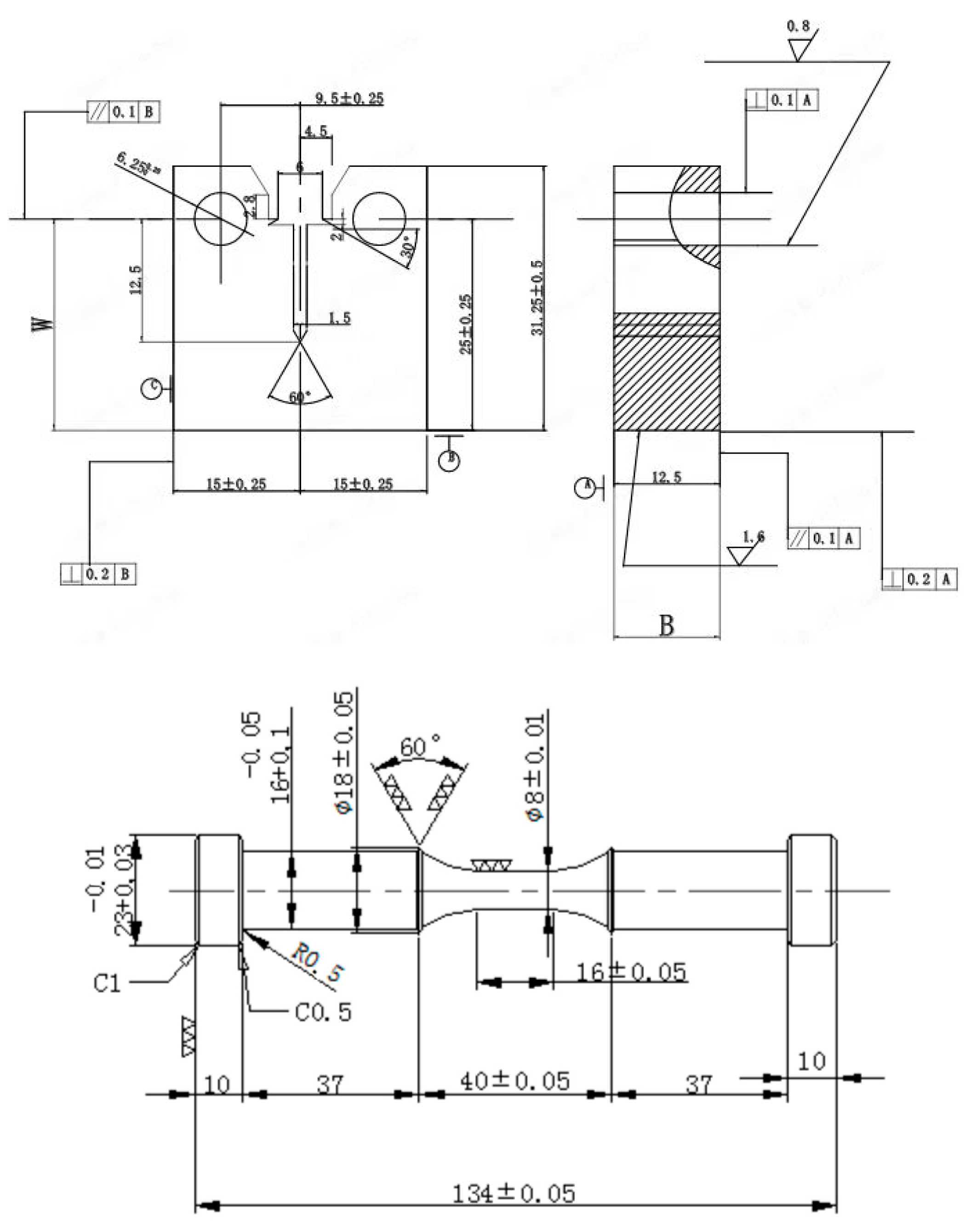
2.2. Specimen Design

The specimen used for corrosion fatigue testing cut initially by wire-electrode cutting according to the drawing of specimen shown in Figure 2. The size of the specimen was 0.5T CT (compact type).

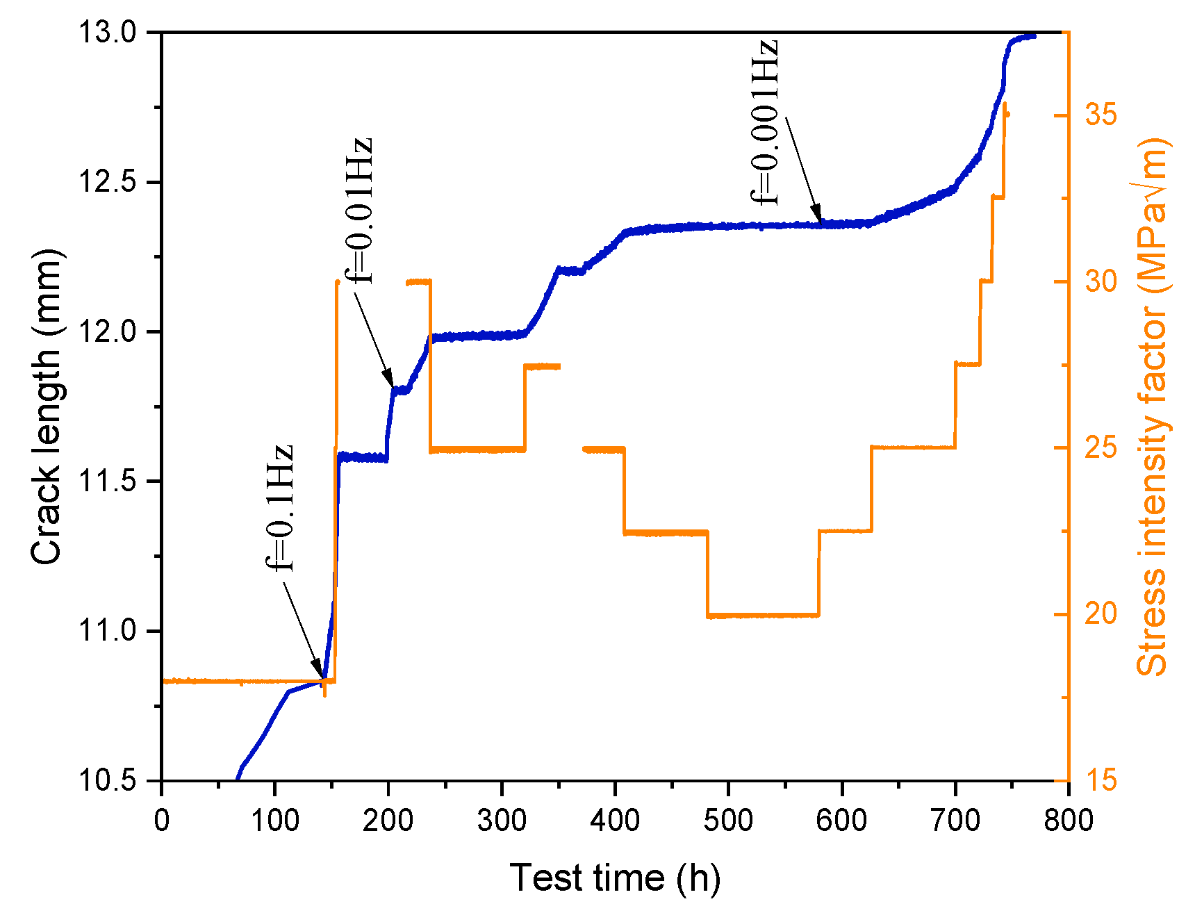
2.3. Crack Growth Rate Test

Before the CGR test, it is necessary to pre-fabricate fatigue cracks on the CT specimen for pre-cracks, which is carried out in air at room temperature. For 0.5T CT specimens, a constant K value of 15 MPa√m can generally be used, and alternating loading with a loading ratio of R = 0.1 and a frequency of f = 2 Hz can be used to obtain fatigue pre-cracks.
All specimens were subjected to the CGR tests by the corrosion fatigue crack test systems with a DCPD (direct current potential drop) device. The test parameters and high-temperature water chemistry were shown in Table 2. After the CGR test, the specimens were pulled out with a tensile machine. The fracture observation was conducted by scanning electron microscopy (SEM).

2.4. TEM and EDS Test

The transmission electron microscopy (TEM, FEI Company, Hillsboro, OR, USA; TECNAI G2 F20) specimen was prepared using a focused ion beam (FIB) at the crack tip. The TEM observation and energy dispersive spectrometer (EDS) was performed in a Tecnai F20 microscope, operated at 200 kV.

2.5. EBSD Observation

The electron backscatter diffraction technique (EBSD) observation was conducted on the cross section of crack tip for the fatigue crack initiation test specimens. The specimens used for the EBSD test were sanded and followed by electropolishing with direct voltage 30 V for 45 s in an electrolyte solution consisting of 20% perchloric acid and 80% ethanol. After that, the specimens were observed by EBSD.

3. Results and Discussion

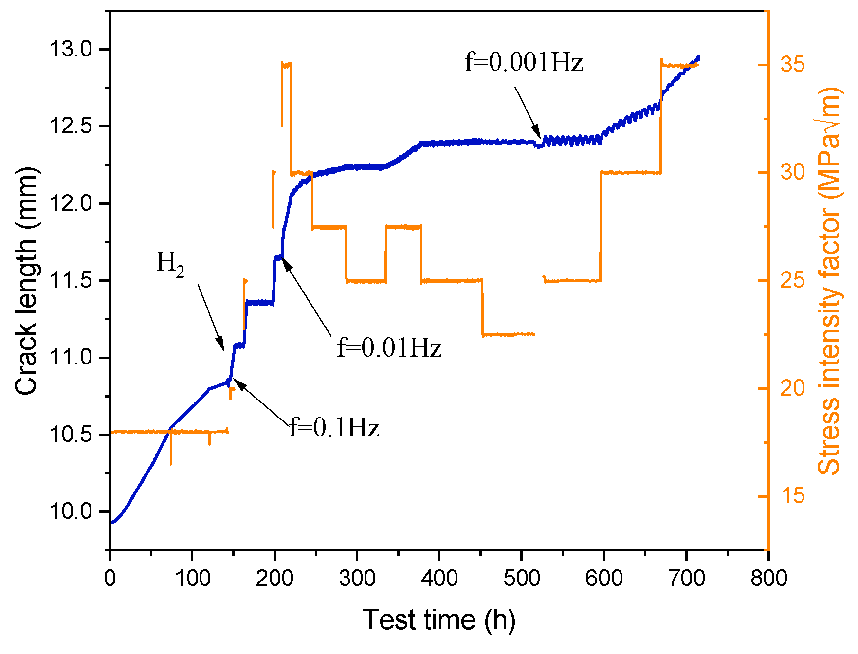
3.1. Crack Growth Rate

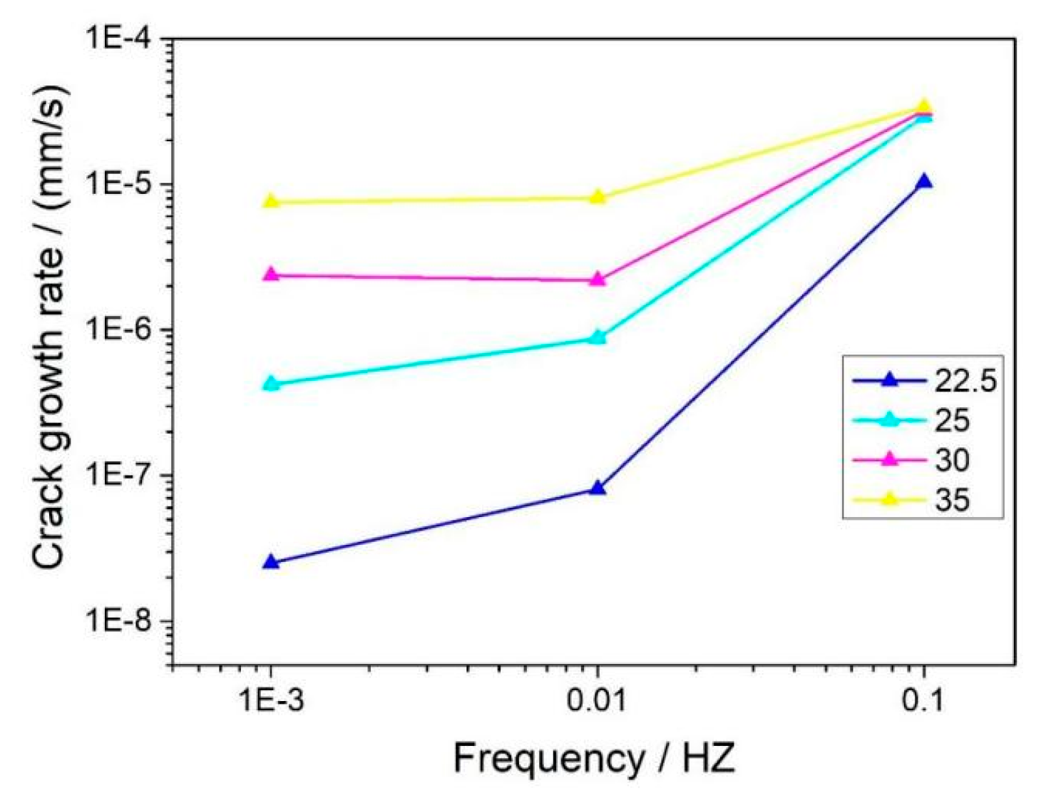
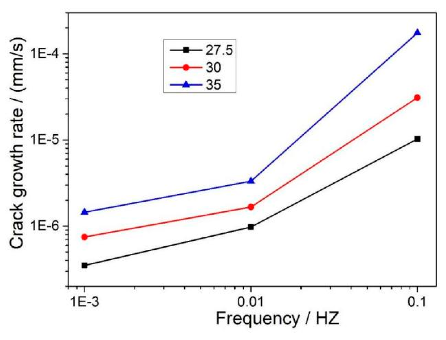
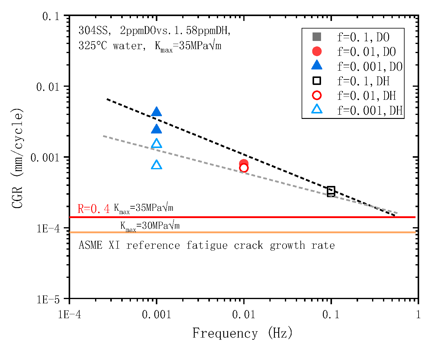
3.1.1. Effect of K and f on CGR

Figure 3 shows the crack growth curve of 304L SS in a 325 °C high-temperature water environment with dissolved oxygen (DO) about 2 ppm under different loading conditions. After about 750 h, the crack length had grown to 13 mm (including the pre-crack). One can see that the crack length was slow, increasing at the beginning with K = 18 MPa√m, while it sharply increased when the K increased to 30 MPa√m. After that, it also can be seen the crack length has a positive correlation with K until it rapidly increases again. As for the f, it shown that the CGR decreased with the decrease in f at the same K. The crack length even stopped growth when the K was below 30 MPa√m at the 0.001 Hz condition. Figure 4 shows the crack growth curve of 304L SS in a 325 °C high-temperature water environment with DH = 1.58 ppm under different loading conditions. After about 720 h test, the crack length was about 12.8 mm, which then rapidly grew to 13 mm. The effect trend of the K and f on the crack length was similar for the DO environment.
Figure 5 and Figure 6 show the effect of K and f on CGR (mm/s) for 304L SS in a DO and DH high-temperature water environment, respectively. One can see that the CGR increased with increasing the K and f of 304L SS in a DO high-temperature water environment. It is worth noting that when the f increases from 0.001 HZ to 0.01 HZ, the increasing range of CGR is much less than it from 0.01 to 0.1. This means that the CGR of the specimen will sharply decrease as the f decreases, which indicates that the CGR is slow when the loading conditions tended towards constant stress. Moreover, comparing Figure 5 and Figure 6, the CGR in the DO environment was obviously faster than it was in the DH water environment, especially at a low f condition. This can be attributed to the DH suppressing water decomposition and reducing material oxidation, which further reduces CGR. However, the effect of water chemistry was not obvious when the fatigue f increased to 0.1. This can be attributed to the mechanical factors dominating under the high f fatigue test process [26,27].

3.1.2. Analysis of CGR Equation

Figure 7 shows the CGR (mm/cycle) equation curves for 304L SS under different conditions, fitted by crack experiment results. It can be seen that the CGR increased with increasing the K under the same f and water environment, while it decreased with increasing the f. It should be noted that the unit of CGR is mm/cycle in this part, and different to Section 3.1.1. Comparing the results of the different test environments, the CGR in the DH high-temperature water was slower than in the DO environment, as mentioned above. Figure 8 shows the effect of f on the CGR, obtained by fitting the above experimental results. The detailed analysis is as follows.
In the DO environment, the corrosion fatigue crack growth test starts from the condition of K = 18 MPa√m and f = 0.1 Hz. During the test, the fatigue f was kept constant and K continuously increased and the CGR curves at K = 20–35 MPa√m was obtained. The results indicated that the larger the value of K, the faster the CGR under the condition of constant f. After that, the CGR at different K values was obtained by change frequency under the conditions of f = 0.01 and 0.001 Hz.
Figure 7 shows the fitting relationship of CGR and ∆K under the 325 °C high-temperature water environment. The exponent of equation represents the dependence of CGR on ∆K. According to the fitting results, the exponent value decreased with decreasing the f. They change from 1.52 to 1.12 corresponding the f from 0.01 to 0.001 in the DO environment, similar to the change from 2.2 to 1.6 in the DH environment. Comparing the fitting formulas in the DH and DO environments, the exponent increased from 1.12 to 1.6 under f = 0.001 HZ, similar to the increase from 1.52 to 2.2 under f = 0.001 HZ. It indicated that the water environment can affect the correlation between the crack growth and mechanical loading. Through repeated experiments of increasing and decreasing K, it is shown that the CGR obtained under the same conditions have small differences and the experiment has good repeatability.
Figure 8 shows the relationship between fatigue frequency f and CGR of 304L SS in the 325 °C high-temperature water environment. The American Society of Mechanical Engineers (ASME) standard results tested in Ar environment are also shown [4,28,29,30]. The effect of DO and DH on CGR are also reflected in the figure as the K value is set to 35 MPa√m. It can be seen that the CGR continuously decreased with increasing the f. The CGR in the DO environment is significantly higher than that in the DH environment at the same test condition. The effect of the high-temperature water environment on the CGR increased with decreasing the f. The test results were similar for multiple specimens at same test condition, which indicates that the results of this study are stable and reliable.
These results were attributed to the fact that the lower the f, the longer the time for one fatigue cycle. So, the more obvious the effect of the high-temperature water environment on the crack tip. The effect of high-temperature water chemistry on CGR is attributed to the fact that DO can accelerate the oxidation at the crack tip. The oxide film formed at the crack tip is generally more brittle, leading to accelerated crack propagation. On the contrary, it will continuously inhibit the decomposition of the high-temperature water and reduce the free oxygen in the solution when DH is present in the environment. The oxidation process at the crack tip would slow down, and thus decrease crack growth. At the same time, the higher f leads to the shorter the single cycle period, so the weaker the effect of stress and environment on the specimen, resulting in a slower CGR. Compared to the ASME standard, the material performance of fatigue used in this study meets the standard. The CGR of 304L SS under the condition of K = 35 MPa√m is not higher than that in the standard tested in argon environment with K = 30 MPa√m. The material can only be used after the related properties meet the design requirements of ASME standard. In this study, the high-temperature water environment was more demanding than the argon gas environment, and the K value was also higher than the standard. It can be inferred that the corrosion fatigue performance of 304L SS is qualified under the design conditions of the ASME standard.
Based on the above data analysis, the trend of CGR shows a synergistic acceleration effect under the coupling effect of K and f under the high-temperature water environment. This further promotes crack growth and accelerates material failure under complex stress conditions. After synergistic acceleration, the CGR of the 304L SS increases by about an order of magnitude. Similarly, the effect of DO = 2 ppm environment has also increases the CGR about one order of magnitude than the DH = 1.58 ppm environment.

3.2. Effect of Fatigue Loading on Crack Tip Characteristic

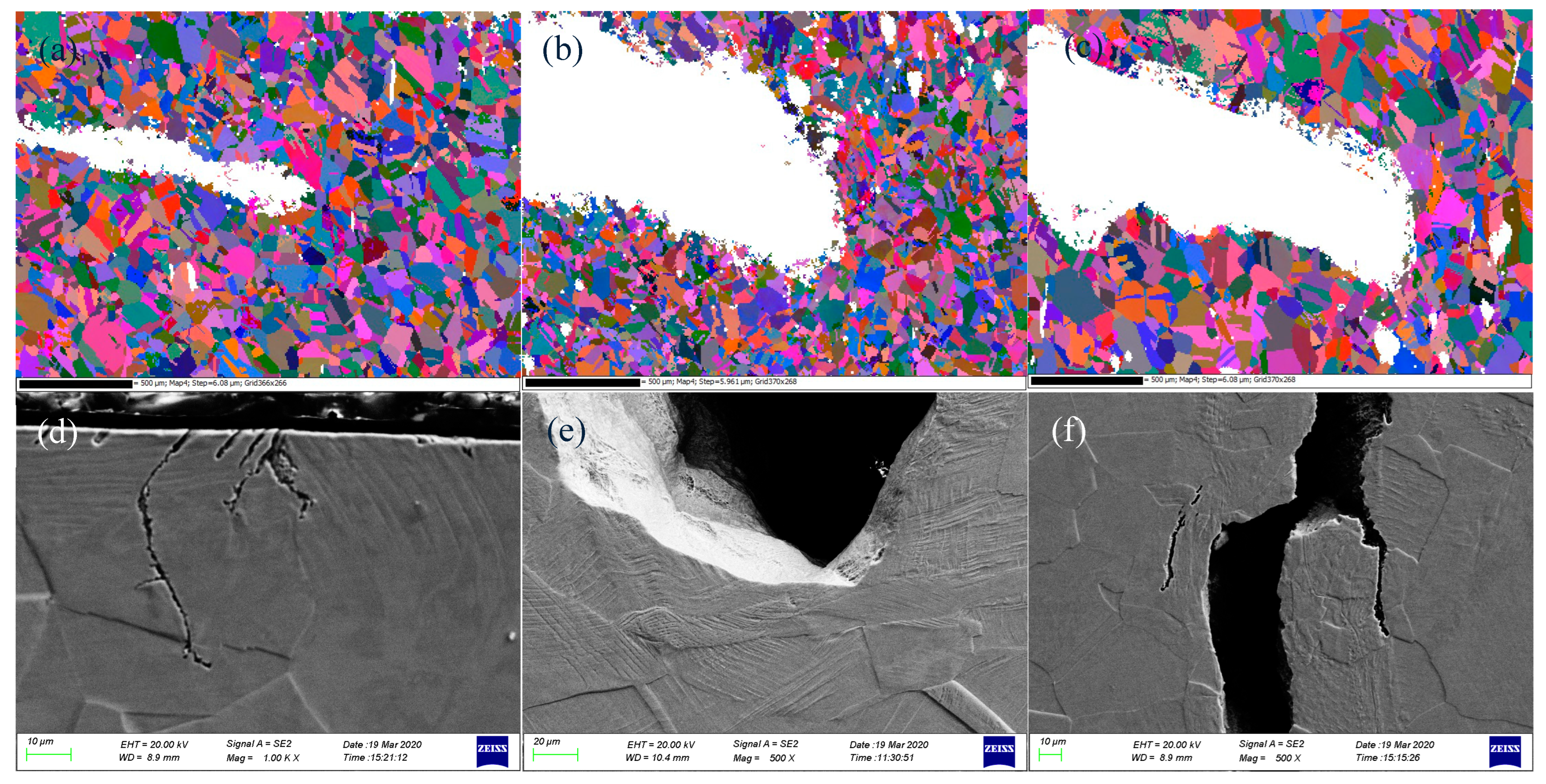
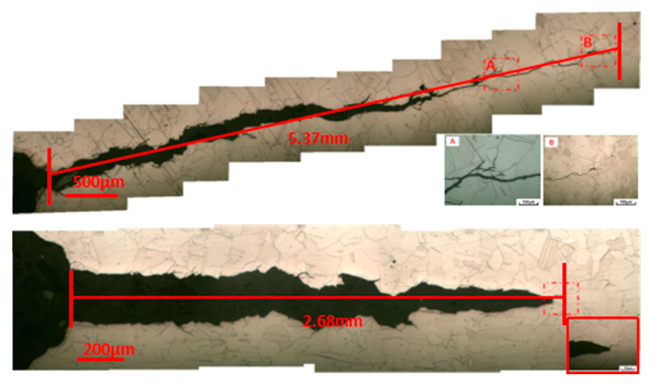
3.2.1. Overall Morphology of the Crack Tip

The crack growth paths in the DO and DH high-temperature water environments are shown in Figure 9, respectively. In both environments, the crack growth shows a transgranular cracking type. Secondary cracks were observed along the crack growth path around the crack tip. The initiation of the secondary crack reduces stress concentration at the tip of the main crack, thereby reducing the strain at the crack tip and delaying the growth rate of the main crack to some extent.
The corrosion fatigue tests were conducted on the rod-shaped specimen in order to investigate the characteristics of crack initiation process and crack tip of 304L SS under same high-temperature water environment. Figure 10 shows the EBSD image of the crack tip for 304L SS. One can see that the crack tip in Figure 10a is in the early stage with relatively narrow cracks, while the cracks in Figure 10b,c are in the late stage with relatively wide cracks. It also can be seen from the figure that there are some areas with a lower calibration rate (white edge areas) around the crack tip that have undergone plastic deformation during the crack growth, induced by an increase in residual stress or strain and a decrease in calibration rate. It can be seen that there was some crack initiation near or along the persistent slip bands (PSBs), and the PSBs or significant plastic deformation around the crack tip. The cracks in Figure 10d were formed in the area of PSBs, one crack shows a typical extension along the direction of PSBs. The crack tip in Figure 10e is characterized by significant plastic deformation. Figure 10f shows the cross-sectional morphology of the middle part of the crack with abundant PSBs and plastic deformation on both sides of the crack. In one word, PSBs is an important mode of fatigue crack initiation [31].

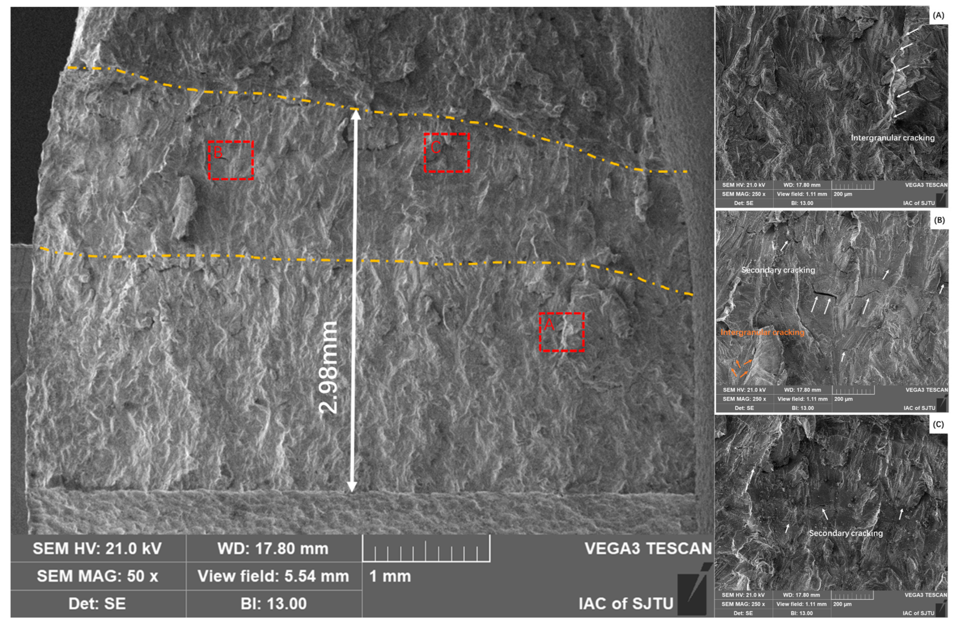
3.2.2. Fracture Morphology of the Crack Tip

The fracture morphologies of the crack tip after CGR test of the 304L SS specimens in the high-temperature water environment under two loading conditions is shown in Figure 11 and Figure 12. The fracture surface under both stress conditions exhibits typical intergranular cracking characteristics with a “river pattern” cleavage fracture morphology. Secondary cracks were observed in the morphology under both loading conditions, especially in the high tensile stress condition. In Figure 11A,B zones show typical secondary cracking morphologies. In Figure 12, the secondary cracks can be seen everywhere, as the locally enlarged areas were shown in the A, B, and C zones. This indicates that the specimen is more prone to initiated secondary cracks under high tensile stress conditions. The fatigue stress can cause local stress concentration in the crack tip with the higher loading, resulting in a more serious concentration, thereby promoting the initiation of secondary cracks.

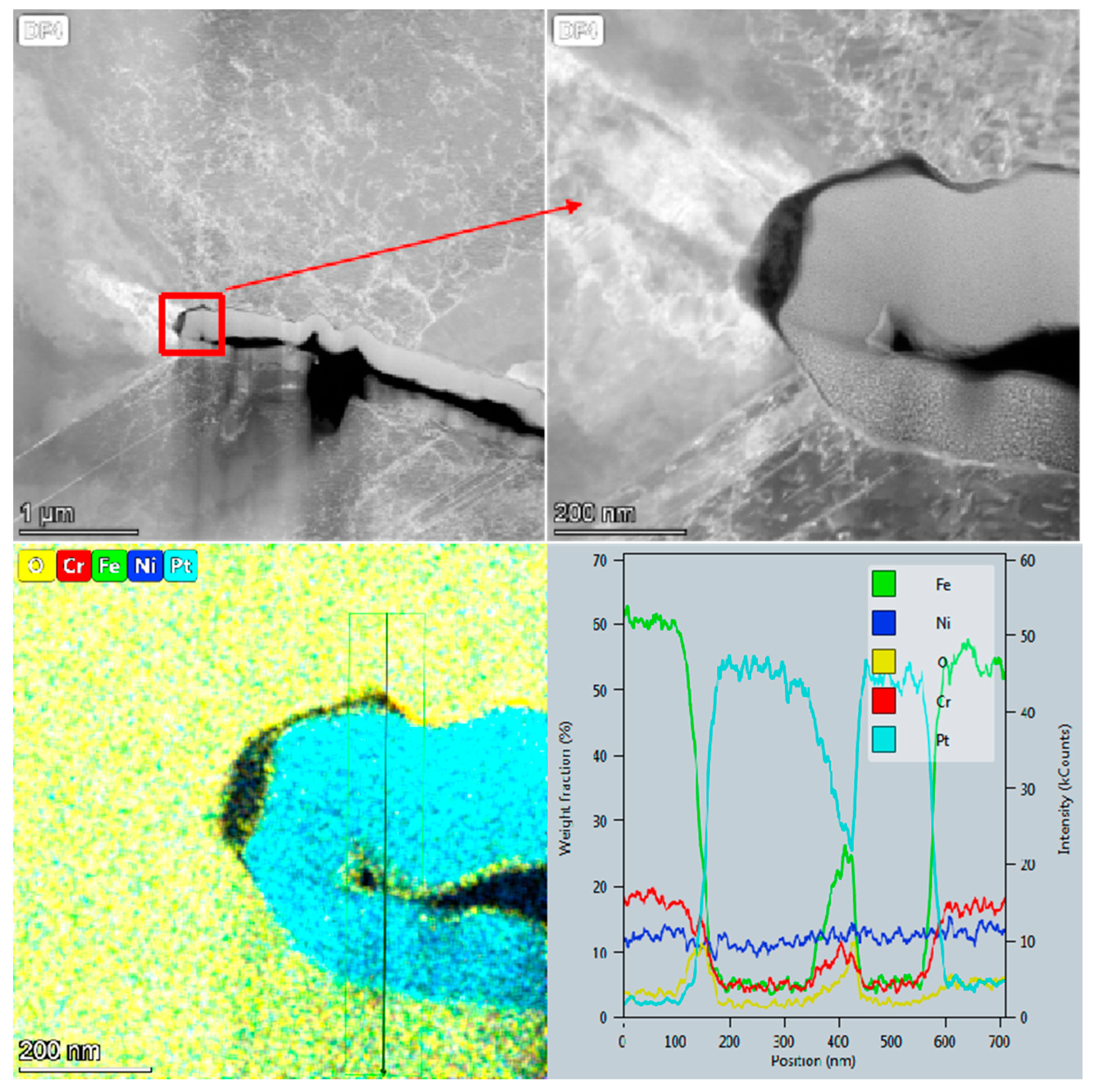
3.2.3. Oxidation Behavior at the Crack Tip

TEM specimens were prepared by FIB at the crack tip of the 304L SS specimens after the corrosion fatigue test in the high-temperature water environment. The crack tip morphology observation and element composition was analyzed by EDS, as shown in Figure 13 and Figure 14. Both the element distribution along the crack tip and growth path is similar, and only a small amount of oxide was observed at the crack tip and along the growth path. The content line scan of elements at the crack tip revealed an enrichment of oxygen in the oxide layer near the crack tip and a decrease in Fe and Cr content; meanwhile, the Ni content did not change significantly. Furthermore, it can be deduced that the oxide structure was divided into different layers, with the outer layer being Fe oxide, such as Fe2O3 or Fe3O4, and the inner layer being Cr oxide such as Cr2O3 [32,33,34,35].
Comparing the crack tip morphology and chemistry composition under two loading conditions in high-temperature water shows significant differences. Firstly, the crack tip is blunt under low tensile stress, while it is sharp under higher tensile stress. Secondly, Cr enrichment is observed on the crack surface under higher tensile stress, indicating the formation of Cr oxide such as Cr2O3. Fe enrichment is observed further away from the crack surface, indicating the formation of Fe oxide such as Fe2O3 or Fe3O4, as indicated in Figure 14. It can be inferred that a dual-layer oxide film, consisting of an outer iron-rich layer and an inner chromium-rich layer is formed [36,37]. Only a small amount of oxide is observed on the edge of crack test at low tensile stress, which may be due to the dissolution of oxide for a long time. Moreover, the oxidation kinetics on the inter oxide layer can induce the Cr enrichment in the high-temperature water environment, as indicated in Figure 13 and Figure 14 [33].
It can be concluded that the CGR significantly increases and the crack tip becomes sharper under high tensile cyclic stress in the high-temperature water environment, while the CGR is slower when the tensile stress is low, and the crack tip stays in the high-temperature water environment for a longer time, resulting in the dissolution or drop of the oxide film into the water. This is consistent with the results of CGR expansion mentioned earlier.

3.3. Mechanism of Crack Growth at Crack Tip

The process of crack tip growth in a corrosion fatigue test in the high-temperature water environment is referenced in Figure 9 in published paper, and can be divided into four steps [13]. Firstly, the specimen surface or crack tip is subjected to fatigue tensile stress, forming a slip band and fresh matrix metal exposed at the beginning of the corrosion fatigue test. Secondly, the fresh metal is often active and easily oxidized by high-temperature water to form metal oxides such as Fe2O3, Fe3O4, Cr2O3. Thirdly, when the tensile stress is unloaded and compressive stress is applied, the previously extruded metal was penetrated into the matrix metal with the movement of the slip band. So, the metal oxides were brought into the subsurface of the specimen. Fourthly, more oxidation products were brought into the subsurface with the continuing of fatigue stress cycles of the material during the fatigue cyclic stress. This process leads to the continuous increase of oxides in the matrix metal around the crack tip, and the crack continues to initiate or propagate forward with the loading of fatigue stress.
Comparing different loading conditions, it can be observed that crack growth is slower when the f is low, as shown above. This can be attributed to there being fewer cycles applied, resulting in less opportunity for oxide products to penetrate into the material matrix. Although more oxides are formed at low f, the CGR at crack tip is slower. Similarly, the CGR is very slow in SCC experiments under constant stress due to almost no oxide penetrating into the matrix metal without reciprocating movement as cyclic stress. The stress level and stress intensity factor K also have a significant impact on the CGR, as it becomes faster and the crack tip is sharper with more secondary cracks on the fracture surface under high stress levels. On the contrary, the CGR is slower and the crack tip is blunter under low stress levels.
High-temperature water chemistry also has a significant effect on crack growth. DO significantly increases the CGR of the specimen, while a DH environment can reduce the CGR [12,38]. This is because DH can inhibit the decomposition of high-temperature water and reduce metal oxidation, as mentioned above. By analyzing the combined effects of stress and environment, it can be concluded that the formation of oxide at the crack tip and its interaction with the base metal in a high-temperature water environment determines the CGR [16,39]. Consequently, the more oxides are formed, the more cycles at higher stress levels, leading to the faster the CGR.
Moreover, the slip bands formed on the specimen surface and crack tip during tensile loading would be longer and more fresh metal would be exposed under constant stress and cyclic stress. Therefore, the more fresh metal that is exposed under the combined action of tensile stress and cyclic stress, the more oxides or corrosion products are formed, resulting in more oxides penetrating into the matrix and causing more damage to the specimen. This ultimately leads to faster crack initiation and propagation. Consequently, the crack growth was obviously accelerated under the combined action of constant stress and periodic cyclic stress.

4. Conclusions

In this study, the fatigue crack growth behavior of 304L SS in a 325 °C, high-temperature water environment was investigated. Based on the experimental results, the main conclusions are as follows.
(1)
In a 325 °C high-temperature water environment, the CGR of 304L SS increased with increasing the stress intensity factor K, stress level, and fatigue frequency. Compared to DH in a high-temperature water environment, DO significantly increases the CGR about an order of magnitude higher.
(2)
Under high tensile cyclic stress levels, the crack tip of 304L SS in a high-temperature water environment is sharper, with more secondary cracks on the fracture surface, while the crack tip under low tensile cyclic stress levels is blunter with relatively fewer secondary cracks.
(3)
A dual-layer oxide film consisting of an outer iron-rich layer and an inner chromium-rich layer is formed in the crack growth path under high tensile cyclic stress levels. However, only a small amount of oxide is observed on the crack surface due to the dissolution of water over a long period of time under lower tensile cyclic stress.
(4)
The fatigue crack growth behavior of 304L SS in a high-temperature water environment depends on the interaction between oxidation at the PSB and the base metal.

Author Contributions

Conceptualization, H.W. and X.L.; methodology, H.W. and C.X.; investigation, H.W., Y.L. and J.Y.; data curation, W.J. and W.Q.; writing—original draft preparation, H.W. and P.W.; writing—review and editing, X.J. and Y.L.; project administration, Y.Z.; funding acquisition, H.W. and X.L. All authors have read and agreed to the published version of the manuscript.

Funding

This research was funded by the National Natural Science Foundation of China (Grant No. 52101066) and Major projects on basic and applied basic research of Guangdong province (Grant No. 2019B030302011).

Data Availability Statement

The original contributions presented in the study are included in the article, further inquiries can be directed to the corresponding author.

Conflicts of Interest

The authors declare no conflicts of interest.

Abbreviations

stainless steelSS
electron back scatter diffractionEBSD
transmission electron microscopeTEM
crack growth rateCGR
dissolved hydrogenDH
dissolved oxygenDO
pressurized water reactorPWR
stress corrosion crackingSCC
Compact typeCT
Direct current potential dropDCPD
Scanning electron microscopySEM
focused ion beamFIB
energy dispersive spectrometerEDS
persistent slip bandsPSBs
The American Society of Mechanical EngineersASME
frequency f

References

  1. Xiao, J.; Yu, Q.Z.; Ting, X.; Hao, W.; Yong, C.; Shao, Y.Q.; Gong, X. Effect of heat treatment on fatigue crack growth behavior of 316NG austenitic stainless steel in deaerated water at 325 °C. J. Nucl. Mater. 2021, 557, 153298. [Google Scholar] [CrossRef]
  2. Cui, Y.H.; Zhang, J.L. Research of SCC Prediction Model for 304 Stainless Steel in the High-Temperature Water Environment. Strength Mater. 2021, 53, 573–581. [Google Scholar] [CrossRef]
  3. Wu, H.C.; Yang, B.; Wang, S.L.; Zhang, M.X.; Shi, Y.Z.; Chen, Y.F.; Sun, Y.H. Effect of thermal aging on corrosion fatigue of Z3CN20.09M duplex stainless steel in high temperature water. Mater. Sci. Eng. A 2016, 655, 183–192. [Google Scholar] [CrossRef]
  4. Seifert, H.P.; Ritter, S.; Leber, H.J. Corrosion fatigue crack growth behaviour of austenitic stainless steels under light water reactor conditions. Corros. Sci. 2012, 55, 61–75. [Google Scholar] [CrossRef]
  5. Chiang, M.F.; Young, M.C.; Huang, J.Y. Effects of hydrogen water chemistry on corrosion fatigue behavior of cold-worked 304L stainless steel in simulated BWR coolant environments. J. Nucl. Mater. 2011, 411, 83–89. [Google Scholar] [CrossRef]
  6. Jinlong, L.; Hongyun, L.; Tongxiang, L. Influence of pre-deformation and oxidation in high temperature water on corrosion resistance of type 304 stainless steel. J. Nucl. Mater. 2015, 466, 154–161. [Google Scholar] [CrossRef]
  7. Mukahiwaa, K.; Sceninia, F.; Burkea, M.G.; Plattsb, N.; Ticeb, D.R.; Stairmandb, J.W. Corrosion fatigue and microstructural characterisation of Type 316 austenitic stainless steels tested in PWR primary water. Corros. Sci. 2018, 131, 57–70. [Google Scholar] [CrossRef]
  8. Zhang, W.; Wang, X.; Wang, S.; Wu, H.; Yang, C.; Hu, Y.; Fang, K.; Jiang, H. Combined effects of machining-induced residual stress and external load on SCC initiation and early propagation of 316 stainless steel in high temperature high pressure water. Corros. Sci. 2021, 190, 109644. [Google Scholar] [CrossRef]
  9. Gao, J.; Ziyu, Z.; Jibo, T.; Xinqiang, W.; Xiang, W.; En-Hou, H.; Ke, W. Differences of corrosion fatigue behaviors among 316LN base metal, 316LN heat-affected zone and 308L weld metal in a safe-end weld joint in borated and lithiated high-temperature water. Int. J. Fatigue 2021, 148, 106223. [Google Scholar] [CrossRef]
  10. Zhang, M.; Chenxin, Z.; Huanchun, W.; Yang, B. Effects of Grain Boundary Engineering on the Microstructure and Corrosion Fatigue Properties of 316L Austenitic Stainless Steel. Front. Mater. 2022, 9, 931848. [Google Scholar] [CrossRef]
  11. Wang, J.; Tianyu, Z.; Yaolei, H.; Jinna, M.B.; Fei, X.; Kai, C.; Du, D.; Andresen, P.L.; Zhang, L.; Zhang, M. Environment assisted cracking of 308L weld metal in high temperature water. J. Nucl. Mater. 2021, 557, 153275. [Google Scholar] [CrossRef]
  12. Lu, Z.; Shoji, T.; Meng, F.; Qiu, Y.; Dan, T.; Xue, H. Effects of water chemistry and loading conditions on stress corrosion cracking of cold-rolled 316NG stainless steel in high temperature water. Corros. Sci. 2011, 53, 247–262. [Google Scholar] [CrossRef]
  13. Zhao, W.; Wang, Y.; Zhang, T.; Wang, Y. Study on the mechanism of high-cycle corrosion fatigue crack initiation in X80 steel. Corros. Sci. 2012, 57, 99–103. [Google Scholar] [CrossRef]
  14. Srinivasan, V.S.; Sandhya, R.; Valsan, M.; Bhanu Sankara Rao, K.; Mannan, S.L. Comparative evaluation of strain controlled low cycle fatigue behaviour of solution annealed and prior cold worked 316L(N) stainless steel. Int. J. Fatigue 2004, 26, 1295–1302. [Google Scholar] [CrossRef]
  15. Meng, F.; Lu, Z.; Shoji, T.; Wang, J.; Han, E.; Ke, W. Stress corrosion cracking of uni-directionally cold worked 316NG stainless steel in simulated PWR primary water with various dissolved hydrogen concentrations. Corros. Sci. 2011, 53, 2558–2565. [Google Scholar] [CrossRef]
  16. Du, D.; Wang, J.; Chen, K.; Zhang, L.; Andresen, P.L. Environmentally assisted cracking of forged 316LN stainless steel and its weld in high temperature water. Corros. Sci. 2019, 147, 69–80. [Google Scholar] [CrossRef]
  17. Wang, J.; Tianyu, Z.; Kai, C.; Yichen, B.; Wujiang, M.; Miaomiao, Z.; Guo, X.; Andresen, P.L.; Zhang, L. Investigations on the SCC initiation behavior of cold worked 316 L in high temperature oxygenated water at constant loads. Corros. Sci. 2022, 203, 110336. [Google Scholar] [CrossRef]
  18. Cui, T.; Haiying, D.; Xinhe, X.; Jiarong, M.; Zhanpeng, L.; Tang, Y.; Pan, D.; Lozano-Perez, S.; Shoji, T. Hydrogen-enhanced oxidation of ferrite phase in stainless steel cladding and the contribution to stress corrosion cracking in deaerated high temperature water. J. Nucl. Mater. 2021, 557, 153209. [Google Scholar] [CrossRef]
  19. Cui, T.; Xinhe, X.; Deng, P.; Junjie, C.; Zhanpeng, L.; Yaping, Z.; Yang, S.; Shoji, T. Determining SCC resistance of stainless steel claddings in high- temperature water by constant load crack growth tests and slow strain rate tests. J. Nucl. Mater. 2024, 588, 154796. [Google Scholar] [CrossRef]
  20. Xiong, Y.; Watanabe, Y.; Shibayama, Y.; Zhong, X.; Mary, N. Low-cycle fatigue behaviors of 316L austenitic stainless steels with different surface finishing in simulated pressurized water reactor primary water and an oxygenated, borated, lithiated high temperature water. Corros. Sci. 2021, 190, 109709. [Google Scholar] [CrossRef]
  21. Xu, S.; Wu, X.Q.; Han, E.H.; Ke, W.; Katada, Y. Crack initiation mechanisms for low cycle fatigue of type 316Ti stainless steel in high temperature water. Mater. Sci. Eng. A 2008, 490, 16–25. [Google Scholar] [CrossRef]
  22. Chopra, O.K.; Shack, W.J. Low-cycle fatigue of piping and pressure vessel steels in LWR environments. Nucl. Eng. Des. 1998, 184, 49–76. [Google Scholar] [CrossRef]
  23. Huang, J.Y.; Young, M.C.; Jeng, S.L.; Yeh, J.J.; Huang, J.S.; Kuo, R.C. Corrosion fatigue behavior of low alloy steels under simulated BWR coolant conditions. J. Nucl. Mater. 2010, 405, 17–27. [Google Scholar] [CrossRef]
  24. Gao, J.; Tan, J.; Wu, X.; Xia, S. Effect of grain boundary engineering on corrosion fatigue behavior of 316LN stainless steel in borated and lithiated high-temperature water. Corros. Sci. 2019, 152, 190–201. [Google Scholar] [CrossRef]
  25. Li, Y.F.; Xiao, J.; Chen, Y.; Zhou, J.; Qiu, S.Y.; Xu, Q. Fatigue crack growth of 316NG austenitic stainless steel welds at 325 °C. J. Nucl. Mater. 2018, 499, 353–360. [Google Scholar] [CrossRef]
  26. Lukáš, T.; Ivo, K.; Veronika, M.; Tomáš, V.; Jaroslav, P.; Hutař, P.; Šmíd, M. Advantageous Description of Short Fatigue Crack Growth Rates in Austenitic Stainless Steels with Distinct Properties. Metals 2019, 475, 1–20. [Google Scholar]
  27. Su, T.; Huang, Y.; Xuan, F. Stress corrosion cracking growth rate prediction model for nuclear power turbine rotor steel in a simulated environment. J. Mater. Res. Technol. 2023, 23, 830–844. [Google Scholar] [CrossRef]
  28. Zhang, Z.; Tan, J.; Wu, X.; Han, E.; Ke, W. Corrosion fatigue crack growth behavior of 316LN stainless steel in high-temperature pressurized water. Nucl. Eng. Technol. 2021, 53, 2977–2981. [Google Scholar] [CrossRef]
  29. Zhang, Z.; Tan, J.; Wu, X.; Han, E.; Ke, W.; Rao, J. Corrosion fatigue behavior and crack-tip characteristic of 316LN stainless steel in high-temperature pressurized water. J. Nucl. Mater. 2019, 518, 21–29. [Google Scholar] [CrossRef]
  30. Al-Rubaie, K.S.; Godefroid, L.B.; Lopes, J.A.M. Statistical modeling of fatigue crack growth rate in Inconel alloy 600. Int. J. Fatigue 2007, 29, 931–940. [Google Scholar] [CrossRef]
  31. Vainionpa, A.; Seppanen, T.; Que, Z. Effects of pressurized water reactor environment and cyclic loading parameters on the low cycle fatigue behavior of 304L stainless steel. Int. J. Fatigue 2024, 182, 108231. [Google Scholar] [CrossRef]
  32. Han, Y.; Han, E.; Peng, Q.; Ke, W. Effects of electropolishing on corrosion and stress corrosion cracking of Alloy 182 in high temperature water. Corros. Sci. 2017, 121 (Suppl. C), 1–10. [Google Scholar] [CrossRef]
  33. Wang, S.; Hu, Y.; Fang, K.; Zhang, W.; Wang, X. Effect of surface machining on the corrosion behaviour of 316 austenitic stainless steel in simulated PWR water. Corros. Sci. 2017, 126 (Suppl. C), 104–120. [Google Scholar] [CrossRef]
  34. Cissé, S.; Laffont, L.; Tanguy, B.; Lafont, M.; Andrieu, E. Effect of surface preparation on the corrosion of austenitic stainless steel 304L in high temperature steam and simulated PWR primary water. Corros. Sci. 2012, 56, 209–216. [Google Scholar] [CrossRef]
  35. Xu, J.; Wu, X.; Han, E. The evolution of electrochemical behaviour and oxide film properties of 304 stainless steel in high temperature aqueous environment. Electrochim. Acta 2012, 71, 219–226. [Google Scholar] [CrossRef]
  36. Ti, W.; Wu, H.; Li, C.; Zhang, G.; Xue, F.; Wang, X. Effect of Machining on the Oxide Film Formation of Austenite Stainless Steel in 300 °C High Temperature Water. Mater. Trans. 2020, 61, 1122–1129. [Google Scholar] [CrossRef]
  37. Cheng, X.; Feng, Z.; Li, C.; Dong, C.; Li, X. Investigation of oxide film formation on 316L stainless steel in high-temperature aqueous environments. Electrochim. Acta 2011, 56, 5860–5865. [Google Scholar] [CrossRef]
  38. Xiao, J.; Qiu, S.Y.; Chen, Y.; Lin, Z.X.; Xu, Q.; Xie, H.Y. Effects of dissolved oxygen on corrosion fatigue cracking of Alloy 690(TT) in pressurized water reactor environments. Int. J. Fatigue 2015, 74, 65–70. [Google Scholar] [CrossRef]
  39. Kamaya, M. Environmental effect on fatigue strength of stainless steel in PWR primary water—Role of crack growth acceleration in fatigue life reduction. Int. J. Fatigue 2013, 55, 102–111. [Google Scholar] [CrossRef]
Figure 1. Metallographs of the 304L SS.
Metals 14 00489 g001
Figure 2. Compact type specimen drawing used for the fatigue crack growth test (Up, B: Bold, W: Width) and rod-shaped specimen used for crack initiation process (Down).
Metals 14 00489 g002
Figure 3. Crack growth curve for 304L SS in DO = 2 ppm high-temperature water environment. (Blue: frequency; Orange: K).
Metals 14 00489 g003
Figure 4. Crack growth curve for 304L SS in DH = 1.58 ppm high-temperature water environment. (Blue: frequency; Orange: K).
Metals 14 00489 g004
Figure 5. Effect of K and f on CGR (mm/s) for 304L SS in the DO high-temperature water environment.
Metals 14 00489 g005
Figure 6. Effect of K and f on CGR (mm/s) for 304L SS in the DH high-temperature water environment.
Metals 14 00489 g006
Figure 7. CGR-ΔK equation curves of 304L SS in the DO and DH high-temperature water environment.
Metals 14 00489 g007
Figure 8. Effect of f on CGR of 304L SS in the DO and DH high-temperature water environment.
Metals 14 00489 g008
Figure 9. Fatigue crack growth path of 304L SS in the DO (Up) and DH (Below) high-temperature water environment.
Metals 14 00489 g009
Figure 10. EBSD images and cross-sectional morphology of crack tip after corrosion fatigue tests for 304L SS.
Metals 14 00489 g010
Figure 11. Crack tip morphology of the specimen under low tensile cyclic stress conditions in the high-temperature water environment.
Metals 14 00489 g011
Figure 12. Crack tip morphology of the specimen under high tensile cyclic stress conditions in the high-temperature water environment.
Metals 14 00489 g012
Figure 13. EDS for surface and line scanning analysis of crack tip in the high-temperature water environment under low tensile cyclic stress.
Metals 14 00489 g013
Figure 14. EDS for surface and line scanning analysis of crack tip in the high-temperature water environment under high tensile cyclic stress.
Metals 14 00489 g014
Table 1. Chemical composition of 304L SS (wt.%).
ElementCSiMnPSCrNiMoFe
304L0.0140.410.720.0160.003518.618.410.25Balance
Table 2. Test parameters and high-temperature water chemistry.
Stress RateFrequencyDissolved
Oxygen
Dissolved
Hydrogen
pHConductivityTemperaturePressure
R = 0.30.1, 0.012 ppm1.58 ppm6.60.15 µS/cm325 °C10.5 MPa
Disclaimer/Publisher’s Note: The statements, opinions and data contained in all publications are solely those of the individual author(s) and contributor(s) and not of MDPI and/or the editor(s). MDPI and/or the editor(s) disclaim responsibility for any injury to people or property resulting from any ideas, methods, instructions or products referred to in the content.

