Article

Laser Powder Bed Fusion Processing of Low Cost CoCrFeNiMoxNby High Entropy Alloys with Promising High-Temperature Properties via In Situ Alloying Commercial Powders

by
S. Venkatesh Kumaran
1,2,* and
José Manuel Torralba
1,2
1
IMDEA Materials Institute, 28906 Madrid, Spain
2
Department of Materials Science and Engineering, Universidad Carlos III de Madrid, 28911 Leganes, Spain
*
Author to whom correspondence should be addressed.
Metals 2024, 14(5), 500; https://doi.org/10.3390/met14050500
Submission received: 15 March 2024 / Revised: 16 April 2024 / Accepted: 22 April 2024 / Published: 25 April 2024
(This article belongs to the Section Powder Metallurgy)

Abstract

:
A blend of only commercial powders, including Ni625, CoCrF75, and 316L, were used as the raw material for fabricating non-equiatomic CoCrFeNiMoxNby high entropy alloys (HEAs) through laser powder bed fusion (PBF-LB/M) via in situ alloying, instead of using pure elemental powders, thus reducing the raw materials cost. The rapid cooling inherent in the PBF-LB/M process facilitated the dissolution of Mo and Nb, resulting in a single FCC phase characterized by high relative densities. High-temperature tensile tests were conducted at room temperature, 700 °C, 800 °C, and 900 °C, revealing mechanical properties that surpassed those reported in existing HEA literature. The remarkable strength of the HEAs developed in this study primarily stemmed from the incorporation of Mo and Nb, leading to the precipitation of Mo and Nb-rich lave phases at elevated temperatures. While constraining elongation when confined to grain boundaries, these precipitates enhanced strength without compromising elongation when distributed throughout the matrix. This work is a feasibility study to explore the usage of commodity compositions from the market to develop HEAs using PBF-LB/M, which opens the possibility of using scraps to further the development of new materials. Consequently, this study presents a rapid and cost-effective approach for HEA development, improving efficiency and sidestepping the direct utilization of critical raw metals for sustainable manufacturing. Moreover, this work also underscores the outstanding mechanical performance of these HEAs at high temperatures, paving the way for the design of innovative alloys for future high-temperature applications.

1. Introduction

Since the advent of high entropy alloys (HEAs) in 2004 [1,2], they have attracted significant attention due to the possibility of adding multiple principal elements to obtain unique microstructures and the possibility to fine-tune the properties, which results in high mechanical strength, good ductility, wear resistance, oxidation resistance, and corrosion resistance [3]. These properties result from the four core effects of HEAs, namely, (i) high entropy, (ii) severe lattice distortion, (iii) sluggish diffusion, and (iv) cocktail effect [4]. The definition of HEAs, initially stated as alloys consisting of more than five elements of composition range between 5 and 35 at% [1], has been modified to alloys with a configurational mixing entropy, ΔSmix > 1.5 R, where R is the gas constant [5].
The most common method used to manufacture HEAs has been casting or arc melting [1] due to its convenience and efficiency when more than five elements need to be solidified. However, due to its ultra-high cooling rate, powder metallurgy routes and additive manufacturing have recently shown great potential in developing HEAs with remarkable properties [6,7]. The most prominent additive manufacturing techniques to produce HEAs have been through powder bed systems, either with a laser beam (PBF-LB/M) or with an electron beam (PBF-EB/M), and powder feed systems like laser metal deposition (LMD) [6]. In a powder bed process like the PBF-LB/M, the feedstock should be spherical with a size distribution between 15–63 μm [8] to ensure proper spreadability and fully pre-alloyed by, e.g., gas-atomization or plasma spheroidizing to avoid elemental segregation. This process of pre-alloying for HEAs, which starts from traditional melting and casting to gas-atomizing, is expensive and time-consuming as HEAs involve four or five principal elements, where some of which, like Co [9], are also critical metals. Critical raw metals lack availability and possess serious concerns about its availability in the future, as detailed in the European Union report [10,11,12], which included metals like Co, Mo, and Nb, among others. Therefore, this method is rigid and restricts the development and exploration of next-generation materials like HEAs via PBF-LB/M.
The concept of in situ alloying has been introduced recently in PBF-LB/M, where the constituent elements are alloyed simultaneously during consolidation. For instance, Simonelli et al. explored different feedstocks to print Ti-6Al-4V in PBF-LB/M by simply mixing elemental powders and by using a novel technique called satellite mixing, where the powders were wet mixed with polyvinyl alcohol [13]. Compared to the simply mixed feedstock, the segregations were observed to be significantly reduced with the satelliting technique. In a similar work, Ewald et al. used powder blends to produce HEAs based on Al-C-Co-Fe-Mn-Ni to enable rapid alloy development in PBF-LB/M [14]. The effects of process parameters on the homogeneity and mechanical properties were studied, and it was concluded that an optimized energy input results in a homogenous elemental distribution in the printed parts. In the study by Chen et al. [15], Mn powders were blended with pre-alloyed CoCrFeNi powder. Good printability with a nearly homogenous Mn distribution in the as-printed parts was observed with a high VED of 259.3 J/mm3. Similarly, Sun et al. [16] fabricated CoCrFeNiMn by using elemental powders, and it exhibited slightly lower ultimate tensile strength but higher ductility than the HEA fabricated by fully prealloyed CoCrFeNi powder mixed with Mn elemental powders [15]. In another study by Hou et al. [17], the strength and hardness of CoCrFeNi HEA fabricated by pre-alloyed powders and by elemental powders were comparable, even though a higher energy input was necessary to obtain excellent performance in the case of elemental powders. Unmelted Cr particles were also observed in the overlapping regions of melt pools due to the very high melting point of Cr compared to the rest of the elements.
Since HEAs have four or five elements in almost equiatomic proportions, it is quite difficult to obtain a homogenous elemental distribution by using pure elemental powders, especially when there is a notable difference in the melting points of elements, densities, and a positive enthalpy of mixing between pairs of elements. This is observed in a study by Farquhar et al. [18], where Ti powders were unmelted due to the high melting point, and severe segregations of Cu were found due to its positive enthalpy of mixing with other elements in the HEA. Moreover, pure elemental powders can also be challenging to handle. For instance, in the most widely studied cantor alloy (CoCrFeMnNi), Cr has a high tendency to form chromium oxides, whereas Ni and Co are considered hazardous by the REACH regulations [9,19]. As a solution to this problem, in this work, a blend of commercial powders, which are cheaper and widely available in the market, are explored as a feedstock in PBF-LB/M. As described in our previous works, where this approach was used to develop HEAs using field-assisted hot pressing [20] and spark plasma sintering [21], there are many grades of powders available in the market that belong to the families of metals on which many HEAs are based: Ni, Cr, Fe, Co, Ti, Al, etc. These powders are mass-produced by several manufacturers and can be delivered in large quantities quickly at competitive prices. We term these powders as ‘commodity’ in this work. Recently, Knieps et al. investigated the effect of powder morphology on in situ alloying in PBF-LB/M to enable the selection of correct powder feedstock by using a blend of commercial powders and elemental powders [22]. It was concluded that a multimodal particle size distribution (PSD) increases packing density and enhances process performance. However, no microstructural studies or evaluations of mechanical properties were carried out. After validating the work based on commercial powders for developing cost-effective HEAs [20,21], there have been studies using a similar approach but with the casting technique [23,24,25].
So, in this investigation, The main objectives of this research work are (a) avoiding the use of fully pre-alloyed powders for HEAs which need special atomizing by using critical raw materials which increases the cost, (b) as a solution to (a), to explore the feasibility of using widely available and cheaper commercial commodity powders thus easing the exploration of new HEAs, (c) to facilitate a higher level of recycling of scraps from such commodity alloys paving the way for sustainable manufacturing of HEAs and other next-generation materials. Coming to the choice of materials in this study, CoCrFeNi, being the most studied HEA due to its exceptional ductility and fracture toughness [26], was used as a basis to which high atomic size elements Mo and Nb were incorporated into it through the commercial powders. Mo and Nb are recognized for their ability to augment both room and high-temperature strength in the alloy [27,28]. Corresponding commercial powders were carefully selected and blended in precise proportions, yielding two distinct HEAs: Co25.45Cr19.2Fe26.6Ni25.2Mo3Nb1.65 and Co21.4Cr26.62Fe24.8Ni21.4Mo3.9Nb2.5. Similar alloys were previously developed in our earlier work using spark plasma sintering, revealing the presence of precipitates rich in Mo and Nb [21]. The literature indicates that large-sized atoms such as Mo and Nb tend to induce the formation of topologically closed packed phases (TCP), including σ, µ, and Laves phases, thereby compromising alloy ductility [29]. However, ultra-high cooling processes like PBF-LB/M have demonstrated the capability to suppress the occurrence of these TCP phases. Consequently, this prevents the reduction in ductility by increasing the solubility of Mo and Nb. The resulting elevated lattice distortion enhances the mechanical properties of the alloys, a phenomenon further explored in this study.

2. Materials and Methods

The gas-atomized powders used in this work were Ni 625, CoCrF75, 316L, and Invar36. Ni 625 and CoCrF75 powders were provided by VDM metals (Werdohl, Germany), 316L powders by Carpenter additive (Widnes, UK), and Invar36 by Sandvik Osprey (Neath, UK). The particle size range of all the powders was between 15 and 45 µm. The average particle sizes and compositions of powders are given in Table 1. It was important to keep the average particle size of the powders closer to each other to ensure good spreadability during PBF-LB/M processing, ensuring high densities.
Based on the composition of the powders, two different alloys, labeled as C1 and C2, were designed to keep them reasonably equiatomic. The powders were simply mixed in appropriate proportions, as given in Table 2, where the final composition of the alloys is also shown. All the powders had good sphericity, as confirmed in the SEM image of the mix of powders shown in Figure 1. To ensure the formation of a solid solution for these compositions, empirical parameters for C1 and C2 alloys were calculated in our previous work [20], which ensured the formation of the FCC phase.
The bulk samples were fabricated by laser beam powder bed fusion system AM 400 from Renishaw (UK) with a focused beam of a diameter of 70 µm. It should be noted that this machine uses a pulsed laser, where the point distance and exposure time calculate the scan speed. The material of the build plate utilized was S 275 steel. Cuboidal samples of 3 × 7 × 7 mm were built for process parameter optimization by varying the laser power, scan speed, and hatch distance with a constant layer thickness of 30 µm. Porosity analysis was carried out by optical microscope and ImageJ to determine the best combination of parameters. The samples were cut along the build direction, polished up to 1 µm diamond paste, and a collage of the whole surface of the samples (7 × 7 mm) was captured at 5x magnification to calculate the porosity levels using ImageJ. To reveal the melt pools, the samples were etched with Aqua regia solution (HNO3:HCl:H2O = 1:3:2) for 5 s. The parameters with the least porosity for C1 and C2 were selected and tested again for reproducibility, which yielded similar porosity levels. The same parameters were selected to print the samples for tensile testing. The optimized parameters and the average porosity amount for C1 and C2 are shown in Table 3 and the results are discuss in Section 4. For tensile testing, solid blocks of samples were printed for both C1 and C2 with the optimized parameters from which flat dog-bone-shaped samples were machined. The gauge dimension of the tensile samples was 12.5 × 3 × 2.5 mm. The tensile tests were performed at room temperature in an Instron 5966 machine at a strain rate of 10−3/s. The high-temperature tensile tests were carried out in a Universal testing machine, MTS 810, according to ASTM E21-20 standard [30]. The heating rate was 100 °C/min, and the exposure time was 30 min. The microstructural and compositional analysis was performed in a FEG-SEM (Apreo 2S LoVac) which is equipped with an EDS and EBSD detector. X-ray diffraction studies were carried out in a PANalytical X-ray diffractometer for phase identification, and the obtained peaks were analyzed with Highscore Plus software 4.9.

3. Results and Discussion

3.1. Thermodynamic Predictions

There are certain empirical parameters that are used to predict the solid solution formation behavior of HEAs, given as follows:
Configurational entropy of mixing: Δ S m i x = R i = 1 n c i l n c i
Enthalpy of mixing: Δ H m i x = i = 1 ,   i   j n 4 Δ H i j m i x c i c j
Atomic size difference: δ = i = 1 n c i 1 r i r ¯ 2 , r   ¯ = i = 1 n c i r i
Valence electron concentration: VEC = i = 1 n C i V E C i
Ω = T m ¯ Δ S m i x Δ H m i x ,   T m ¯ = i = 1 n c i ( T m ) i
where n represents the number of elements, R is the gas constant, r   ¯ is the average atomic radius of the alloy, r i is the atomic radius of the constituent element and is obtained from [31], c i is the atomic fraction of the alloy elements, and T m ¯ is the melting point of the alloy calculated by the rule of mixtures. Ω is a new parameter defined in [32] to predict the formation of a solid solution (SS) phase that reflects the strength of entropy and enthalpy. The values of the empirical parameters for C1 and C2 alloy are calculated and tabulated in Table 4. These parameters, being most applicable to HEAs fabricated by casting/arc melting, might be unsuitable for additive manufacturing because of their rapid cooling rate and ability to suppress unfavorable compounds. However, they provide useful information for designing initial HEA compositions. Both C1 and C2 HEA satisfy all the parameters except Δ H m i x to form SS, i.e., FCC phase, according to the VEC. A large negative value of Δ H m i x Favours formation of an amorphous phase [33], but since both C1 and C2 exhibit FCC phase, as confirmed by XRD and EBSD, we conclude that this parameter model is not strictly applicable to these alloys.

3.2. Porosity Analysis

Porosity analysis was carried out first in the C2 alloy fabricated by SLM. Based on the literature study of the commercial powders used for the initial screening design, a volumetric energy density (VED) of 68–200 J/mm3 was analyzed with laser power (P) in the range of 100–300 W and scan speed (s) in the range from 500–1000 mm/s. The layer thickness (t) and hatch distance (h) were kept constant at 30 µm and 70 μm, respectively. The hatch distance of 70 μm was chosen as a base due to the same value of laser spot size of the Renishaw AM 400 machine. The VED is calculated as P S     t     h . Two additional hatch distances of 50 and 60 µm were used at select combinations to try to reduce the porosities further. The porosity values in percentages for C2 alloy are shown in Figure 2c. The general trend observed was that the porosity amount increased with laser power at a given scanning speed due to over-melting, as seen from the spherical gas pores in Figure 2e,f, whereas too low a power of 100 W also increased the porosity amount due to insufficient melting causing lack of fusion pores as seen in Figure 2a,b. Since the C2 samples achieved high relative densities, the second experimental trial for C2 was used as a starting point for C1 since the compositions were similar to reduce the iterations. The graph for the C1 alloy is included in the supplementary report in Figure S2, along with the C2 graph for the hatch distance of 50 µm. With a laser power of 150 W and a scan speed of 900 mm/s, a hatch distance of 60 µm worked slightly better for C2 alloys than a hatch distance of 70 µm but increased the porosity for C1 alloy. And with the same laser power and scanning speed, a 70 µm hatch distance, i.e., with a reduced VED, could reduce the porosities in C1 alloy. A lower VED perhaps worked better for C1 due to the lower quantity of high melting point elements Mo and Nb compared to C2. The final optimized parameters of C1 and C2 HEA are listed in Table 4. Such reduced porosity levels prove that this HEA system is so well suited to be processed with PBF-LB/M via in situ alloying commercial powders.

3.3. Microstructural Analysis

The microstructures of C1 and C2 alloys along the building direction were studied in SEM, as shown in Figure 3a,b. The microstructure reveals grain boundaries, melt pool boundaries, and various substructures, which are elongated columnar and equiaxed cellular, in the nanoscale within the grains. The grain growth here is typical epitaxial growth in the direction of the maximum temperature gradient, which is typically observed in PBF-LB/M processes. As observed in the literature, the boundaries of the substructures might be enriched in heavy elements like Mo and Nb [35] and possess a high density of dislocations [36], which restricts dislocation movement and enhances the strength of the alloy. The high dislocation density can be attributed to the rapid cooling process in PBF-LB/M.
X-ray diffraction was performed on the alloys to identify the phase structure. As shown in Figure 4a, both C1 and C2 alloys showed only FCC peaks confirming the single-phase solid solution structure in the as-built stage itself. Controlling segregations by in situ alloying remains a challenge due to the random mixture of powders in the feedstock and lack of time for proper homogenization in the micro-sized melt pool at such high cooling rates, due to which it is difficult to predict the composition at any point in the blend and inside the melt pool as well. Reducing the number of elemental powders by using a mix of commodity powders to produce HEAs offers a better solution since most of the elements are already alloyed. As shown in Figure 4b for C1 alloy and Figure 4c for C2 alloy, even when the feedstock is a blend of powders, the processed alloys show almost a homogenous elemental distribution with remarkably high relative densities of 99.9%, proving the feasibility of this novel method of using commodity powders. Some minor heterogeneities are observed along the melt pool boundaries for C1 alloy, as shown in Figure 4b, which is quite negligible compared with common in in situ alloyed microstructures with a single melt [18,37]. However, this can be fixed by a short homogenization treatment, which is beyond the scope of the current feasibility study. To further confirm the phases, EBSD analysis was performed, and the results are shown in Figure 5. Both C1 and C2 alloys had a single FCC phase in the as-built state, which shows that the developed alloys, as predicted by the calculations in [20], are indeed HEA. The grain morphology is columnar along the build direction, as expected in the PBF-LB/M process. Both the alloys had the same average grain size of 20 μm as measured from the EBSD with a critical misorientation angle of 10⁰, which shows that the higher amount of Mo and Cr in the C2 alloy had no effect on the grain size.

3.4. Mechanical Properties

Tensile tests were performed on the as-built samples and tested parallel to the build direction to obtain the minimum strength possible with the alloys as the mechanical properties would be better after heat treatment and, if tested, normal to the build direction. The yield strength (YS) and ultimate tensile strength (UTS) of C1 and C2 obtained from the tensile test are compared with similar HEAs mostly obtained by vacuum arc melting (VAM) with an FCC phase in Figure 6. The effect of Mo and Nb dissolution in C1 and C2 alloys processed by PBF-LB/M on the strength is clearly observed through this plot. Notably, the strength values of C1 and C2 are also higher than when they were processed by Spark plasma sintering (SPS) in our previous work [21], proving the superiority of PBF-LB/M. Both the YS and UTS of C1 and C2 decrease with temperature as expected due to dynamic softening occurring at high temperatures [38], and C2 exhibits a higher yield and ultimate tensile strength than C1 at room and high temperatures due to the former’s higher Mo, Nb, and Cr content which induces local lattice distortion [39], thus hindering dislocation movement. As seen in Table 3, the atomic size difference, δ , is slightly higher for C2, which enables higher lattice distortion. The highest strength is attained by C2 alloy with a YS and UTS of 539.6 MPa and 752 MPa at room temperature to 203.5 MPa and 272 MPa at 900 °C, respectively. The summary of the mechanical properties, including elongation, is tabulated in Table 5. Figure 6 also shows that C1 and C2 exhibit better mechanical behavior at both room and high temperatures compared to similar HEAs containing Al and Mo [40,41,42,43,44,45], some of them even having eutectic microstructures, thus proving that by this method, it is possible to achieve competitive mechanical properties at lower cost. The cost savings considering only the raw materials amounted to 20% for the C2 alloy, as shown in Figure 7, as calculated in our previous work [21]. The calculation for elemental powders excludes the cost of ingot casting and gas atomizing, which will eventually amount to much higher savings.

3.5. Fracture Behaviour

As seen in Table 5, C1 alloy exhibits a sudden drop in ductility at 900 °C. To explore this further, the gauge region of the tensile samples after fracture at high temperatures was examined in SEM to observe the microstructural changes. It can be seen from Figure 8a,b that the grains and substructures were elongated as expected. Notably, in Figure 8(c2), there are precipitates shown in white along the grain boundaries in the sample tested at 900 °C. An XRD analysis of the fractured samples did not show any peaks other than FCC due to the low volume fraction of precipitates as shown in Figure S3 in the supplementary report, but an EDS line scan revealed that they are rich in Mo and Nb. Mo and Nb are known to form secondary intermediate phases in high entropy alloys when their quantities exceed the solid solubility limit [26]. Specifically, Fan et al. [46] found that a Nb and Mo-enriched hexagonal close-packed structure Laves phase was formed upon alloying Nb and Mo to CoCrFeNi via arc melting. Thus, the precipitation happening at high temperatures in the C1 and C2 alloys could well be the lave phase. Evidently, the cracks initiated from these precipitates and propagated rapidly along the grain boundaries, as seen in Figure 8(c3), resulting in embrittlement. This explains the sudden drop in elongation of C1 alloy tested at 900 °C, as seen in Table 5, and is consistent with the cleavage fracture morphology, as shown in Figure 9(a4). So, at 900 °C, the fracture changes from ductile to brittle fracture. At other temperatures tested, the C1 alloy exhibits promising elongation along with very high strength for an FCC phase, which corresponds well with the ductile fracture morphology with dimples, as shown in Figure 10(a1–a3).
In the C2 alloy, the volume fraction and size of Mo and Nb-rich precipitates exhibit a gradual increase from 700 °C to 900 °C, as illustrated in Figure 10(a–c). At 900 °C, nano-precipitates are uniformly dispersed throughout the C2 alloy, contrasting with C1, where precipitates were solely present along grain boundaries. Consequently, C2 demonstrates superior elongation and a ductile fracture morphology, as depicted in Figure 10(b1–b3). Beyond enhanced solid solution strengthening, precipitation hardening significantly contributes to C2 alloy’s superior strength compared to C1 above 700 °C, as seen in Table 4. Notably, C2, characterized by higher Mo and Nb content, exhibits greater strength than C1 at all temperatures without compromising ductility. A study by Wei et al. [47] explored the increment in yield strength in CoCrFeNi-based HEA through small additions of Si, maintaining ductility. The simultaneous increase in strength and ductility was attributed to a decrease in stacking fault energy, the formation of deformation nano twins, and possible short-range order. Therefore, our future research will focus on investigating similar effects resulting from small additions of Mo and Nb to these alloys, along with an examination of precipitate formation at high temperatures, aspects beyond the current scope of this study.

4. Conclusions

In this work, two low-cost non-equiatomic HEAs based on CoCrFeNiMoxNby were designed and processed by PBF-LB/M via in situ alloying commercial powders like Ni superalloy and stainless steel. Its processability, microstructure, and mechanical properties in rooms and at high temperatures were evaluated in this study. The main conclusions regarding the success of mixing commodity compositions and the alloys designed are as follows:
  • The designed alloy compositions C1 and C2 achieved excellent printability after optimization, reaching densities close to 99.9% with no defects. In the as-built state, the alloys had a complete FCC matrix with almost a homogenous distribution of elements with no deleterious secondary phases;
  • Both C1 and C2 alloys achieved competitive mechanical properties, with C2 alloys exhibiting better strength from room temperature to 900 °C than C1 due to the former´s higher Mo and Nb content, enabling higher lattice distortion. Considering that no microstructure homogenization treatment has been carried out yet to improve the properties further, this approach to manufacturing HEAs through the hypothesis of pre-alloyed powder mixing is indeed promising;
  • Both the alloys exhibited good ductility at all temperatures except for C1 at 900 °C which suffered embrittlement due to the presence of Nb and Mo-rich laves precipitates along the grain boundaries, as opposed to C2, where the precipitates were dispersed throughout the matrix;
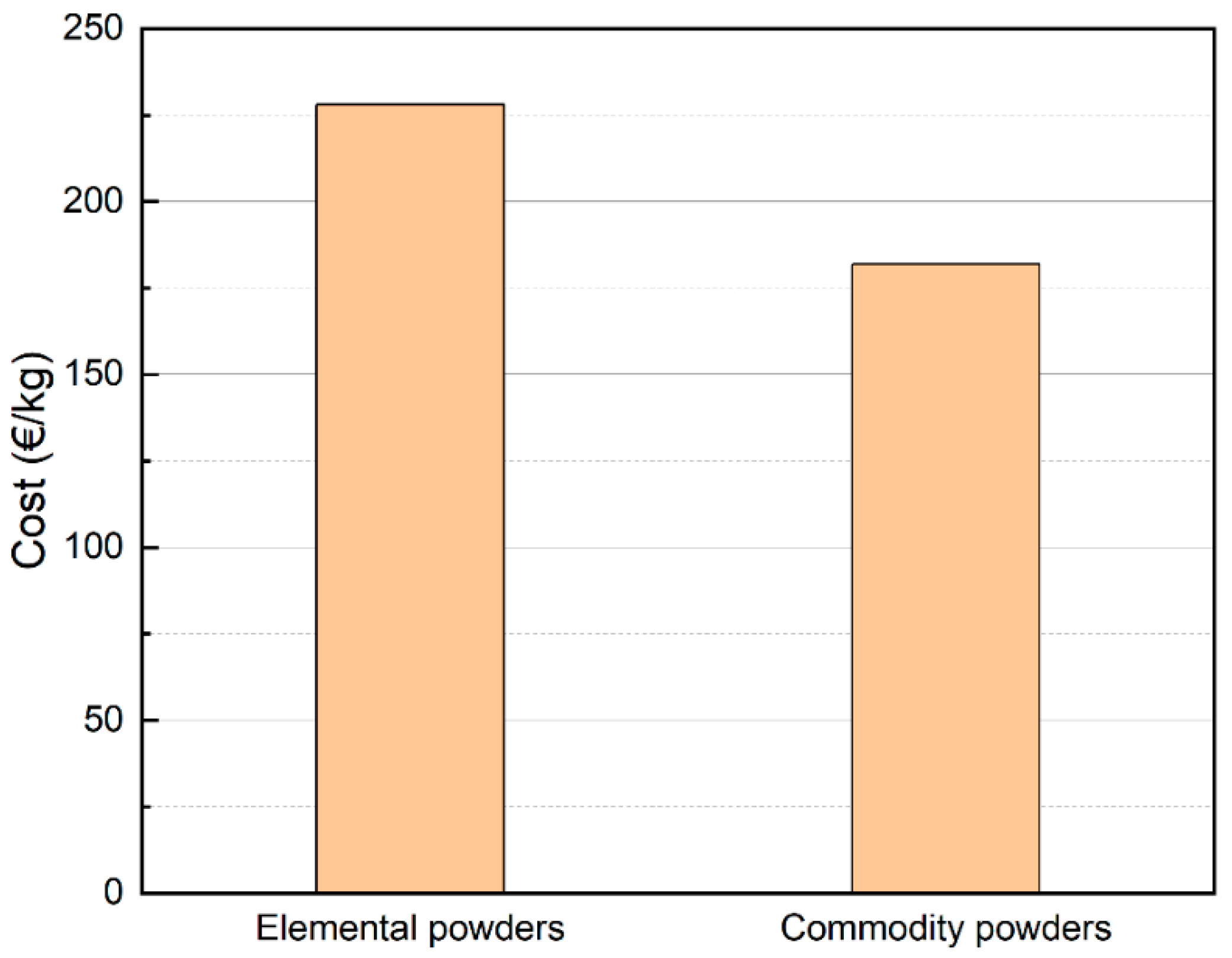
  • Utilizing this approach resulted in a significant reduction in the cost of raw materials by 20%, not factoring in savings from ingot casting and gas atomization. Consequently, this method facilitates the commercialization of HEAs by providing an efficient and cost-effective avenue. Furthermore, it opens the possibility of employing scrap-based compositions to achieve a HEA microstructure.

Supplementary Materials

The following supporting information can be downloaded at: https://www.mdpi.com/article/10.3390/met14050500/s1, Figure S1: Porosity percentage plotted against Scan speed for various laser powers printed with a hatch distance of 50 µm and layer thickness of 30 µm for C2 alloy; Figure S2: Porosity percentage plotted against Scan speed for various laser powers printed with a hatch distance of (a) 50 µm and (b) 70 µm and layer thickness of 30 µm for C1 alloy; Figure S3: XRD plot of C2 alloy after tensile testing at 900 °C at a step size of (a) 0.0262° and (b) 0.0131°.

Author Contributions

Conceptualization, S.V.K. and J.M.T.; Methodology, S.V.K. and J.M.T.; Investigation, S.V.K.; Writing—original draft, S.V.K.; Writing—review & editing, S.V.K. and J.M.T.; Supervision, J.M.T. All authors have read and agreed to the published version of the manuscript.

Funding

This research received no external funding.

Data Availability Statement

The original contributions presented in the study are included in the article/Supplementary Material, further inquiries can be directed to the corresponding authors.

Acknowledgments

The authors would like to thank the powder suppliers, VDM Metals (Germany), Sandvik Osprey (UK), Carpenter Additive (UK), and MIMETE (Italy) for providing the powders.

Conflicts of Interest

The authors declare no conflicts of interest.

References

  1. Yeh, J.W.; Chen, S.K.; Lin, S.J.; Gan, J.Y.; Chin, T.S.; Shun, T.T.; Tsau, C.H.; Chang, S.Y. Nanostructured high-entropy alloys with multiple principal elements: Novel alloy design concepts and outcomes. Adv. Eng. Mater. 2004, 6, 299–303. [Google Scholar] [CrossRef]
  2. Cantor, B.; Chang, I.T.H.; Knight, P.; Vincent, A.J.B. Microstructural development in equiatomic multicomponent alloys. Mater. Sci. Eng. A 2004, 375–377, 213–218. [Google Scholar] [CrossRef]
  3. Chen, J.; Zhou, X.; Wang, W.; Liu, B.; Lv, Y.; Yang, W.; Xu, D.; Liu, Y. A review on fundamental of high entropy alloys with promising high–temperature properties. J. Alloys Compd. 2018, 760, 15–30. [Google Scholar] [CrossRef]
  4. Zhang, Y.; Zuo, T.T.; Tang, Z.; Gao, M.C.; Dahmen, K.A.; Liaw, P.K.; Lu, Z.P. Microstructures and properties of high-entropy alloys. Prog. Mater. Sci. 2014, 61, 1–93. [Google Scholar] [CrossRef]
  5. Yeh, J.W. Alloy design strategies and future trends in high-entropy alloys. JOM 2013, 65, 1759–1771. [Google Scholar] [CrossRef]
  6. Torralba, J.M.; Campos, M. High Entropy Alloys Manufactured by Additive Manufacturing. Metals 2020, 10, 639. [Google Scholar] [CrossRef]
  7. Torralba, J.M.; Alvaredo, P.; García-Junceda, A. High-entropy alloys fabricated via powder metallurgy. A critical review. Powder Metall. 2019, 62, 84–114. [Google Scholar] [CrossRef]
  8. Cordova, L.; Campos, M.; Tinga, T. Revealing the Effects of Powder Reuse for Selective Laser Melting by Powder Characterization. JOM 2019, 71, 1062–1072. [Google Scholar] [CrossRef]
  9. Cobalt Infocard, European Chemicals Agency. Available online: https://echa.europa.eu/substance-information/-/substanceinfo/100.028.325?_disssubsinfo_WAR_disssubsinfoportlet_backURL=https%3A%2F%2Fecha.europa.eu%2Finformation-on-chemicals%3Fp_p_id%3Ddisssimplesearchhomepage_WAR_disssearchportlet%26p_p_lifecycle%3D0%26 (accessed on 25 August 2021).
  10. Grohol, D.M. Constanze Veeh, Study on the Critical Raw Materials for the EU. 2023. Available online: https://op.europa.eu/en/publication-detail/-/publication/57318397-fdd4-11ed-a05c-01aa75ed71a1 (accessed on 1 March 2024).
  11. Proposal for a Regulation of the European Parliament and of the Council Establishing a Framework for Ensuring a Secure and Sustainable Supply of Critical Raw Materials and Amending Regulations (EU) 168/2013, (EU) 2018/858, 2018/1724 and (EU) 2019/1020; European Commission: Brussels, Belgiei, 2023; pp. 1–23.
  12. Annexes to the Proposal for a Regulation of the European Parliament and of the Council, for Establishing a Framework for Ensuring a Secure and Sustainable Supply of Critical Raw Materials and Amending Regulations (EU) 168/2013, (EU) 2018/858, 2018/1724 and (EU) 2019/1020, 0079; European Commission: Brussels, Belgiei, 2023; pp. 1–23. [CrossRef]
  13. Simonelli, M.; Aboulkhair, N.T.; Cohen, P.; Murray, J.W.; Clare, A.T.; Tuck, C.; Hague, R.J.M. A comparison of Ti-6Al-4V in-situ alloying in Selective Laser Melting using simply-mixed and satellited powder blend feedstocks. Mater. Charact. 2018, 143, 118–126. [Google Scholar] [CrossRef]
  14. Ewald, S.; Kies, F.; Hermsen, S.; Voshage, M.; Haase, C.; Schleifenbaum, J.H. Rapid Alloy Development of Extremely High-Alloyed Metals Using Powder Blends in Laser Powder Bed Fusion. Materials 2019, 12, 1706. [Google Scholar] [CrossRef]
  15. Chen, P.; Li, S.; Zhou, Y.; Yan, M.; Attallah, M.M. Fabricating CoCrFeMnNi high entropy alloy via selective laser melting in-situ alloying. J. Mater. Sci. Technol. 2020, 43, 40–43. [Google Scholar] [CrossRef]
  16. Sun, M.; Wang, B.; Zhang, J.; Lu, B. Intermetallics In-situ synthesis of CoCrFeMnNi high-entropy alloy by selective laser melting. Intermetallics 2023, 156, 107866. [Google Scholar] [CrossRef]
  17. Hou, Y.; Su, H.; Zhang, H.; Wang, X.; Wang, C. Fabricating Homogeneous FeCoCrNi High-Entropy Alloys via SLM In Situ Alloying. Metals 2021, 11, 942. [Google Scholar] [CrossRef]
  18. Farquhar, L.; Maddison, G.; Hardwick, L.; Livera, F.; Todd, I.; Goodall, R. In-Situ Alloying of CoCrFeNiX High Entropy Alloys by Selective Laser Melting. Metals 2022, 12, 456. [Google Scholar] [CrossRef]
  19. Nickel Infocard, European Chemicals Agency. Available online: https://echa.europa.eu/substance-information/-/substanceinfo/100.028.283 (accessed on 25 August 2021).
  20. Torralba, J.M.; Kumarán, S.V. Development of competitive high-entropy alloys using commodity powders. Mater. Lett. 2021, 301, 130202. [Google Scholar] [CrossRef]
  21. Kumaran, S.V.; Garbiec, D.; Torralba, J.M. A novel and sustainable method to develop non-equiatomic CoCrFeNiMox high entropy alloys via spark plasma sintering using commercial commodity powders and evaluation of its mechanical behaviour. Mater. Sci. Eng. A 2023, 878, 145207. [Google Scholar] [CrossRef]
  22. Knieps, M.S.; Reynolds, W.J.; Dejaune, J.; Clare, A.T.; Evirgen, A. In-situ alloying in powder bed fusion: The role of powder morphology. Mater. Sci. Eng. A 2021, 807, 140849. [Google Scholar] [CrossRef]
  23. Hariharan, K.; Sivaprasad, K. Sustainable Low-Cost Method for Production of High-Entropy Alloys from Alloy Scraps. J. Sustain. Metall. 2022, 2, 625–631. [Google Scholar] [CrossRef]
  24. Navazani, M.; Kada, S.R.; Fabijanic, D.; Barnett, M. Increasing ductility via Cu addition in AlxCrFeMnNi: Towards a scrap-based high entropy alloy. Intermetallics 2024, 164, 108100. [Google Scholar] [CrossRef]
  25. Chao, Q.; Joseph, J.; Annasamy, M.; Hodgson, P.; Barnett, M.R.; Fabijanic, D. AlxCoCrFeNi high entropy alloys from metal scrap: Microstructure and mechanical properties. J. Alloys Compd. 2024, 976, 173002. [Google Scholar] [CrossRef]
  26. Liu, W.H.; Yang, T.; Liu, C.T. Precipitation hardening in CoCrFeNi-based high entropy alloys. Mater. Chem. Phys. 2018, 210, 2–11. [Google Scholar] [CrossRef]
  27. Hsu, C.Y.; Juan, C.C.; Chen, S.T.; Sheu, T.S.; Yeh, J.W.; Chen, S.K. Phase diagrams of high-entropy alloy system Al-Co-Cr-Fe-Mo-Ni. JOM 2013, 65, 1829–1839. [Google Scholar] [CrossRef]
  28. Jiang, H.; Qiao, D.; Lu, Y.; Ren, Z.; Cao, Z.; Wang, T.; Li, T. Direct solidification of bulk ultrafine-microstructure eutectic high-entropy alloys with outstanding thermal stability. Scr. Mater. 2019, 165, 145–149. [Google Scholar] [CrossRef]
  29. Gao, X.; Liu, T.; Zhang, X.; Fang, H.; Qin, G.; Chen, R. Precipitation phase and twins strengthening behaviors of as-cast non-equiatomic CoCrFeNiMo high entropy alloys. J. Alloys Compd. 2022, 918, 165584. [Google Scholar] [CrossRef]
  30. ASTM E21-20 Standard; Standard Test Methods for Elevated Temperature Tension Tests of Metallic Materials. ASTM International: West Conshohocken, PA, USA, 2021. [CrossRef]
  31. Kittel, C. Introduction to Solid State Physics, 8th ed.; John Wiley & Sons, Inc.: Hoboken, NJ, USA, 2005; ISBN 0-471-41526-X. [Google Scholar]
  32. Yang, X.; Zhang, Y. Prediction of high-entropy stabilized solid-solution in multi-component alloys. Mater. Chem. Phys. 2012, 132, 233–238. [Google Scholar] [CrossRef]
  33. Guo, S.; Hu, Q.; Ng, C.; Liu, C.T. More than entropy in high-entropy alloys: Forming solid solutions or amorphous phase. Intermetallics 2013, 41, 96–103. [Google Scholar] [CrossRef]
  34. Guo, S.; Ng, C.; Lu, J.; Liu, C.T. Effect of valence electron concentration on stability of fcc or bcc phase in high entropy alloys. J. Appl. Phys. 2011, 109, 103505. [Google Scholar] [CrossRef]
  35. Zhong, Y.; Liu, L.; Wikman, S.; Cui, D.; Shen, Z. Intragranular cellular segregation network structure strengthening 316L stainless steel prepared by selective laser melting. J. Nucl. Mater. 2016, 470, 170–178. [Google Scholar] [CrossRef]
  36. Birnbaum, A.J.; Steuben, J.C.; Barrick, E.J.; Iliopoulos, A.P.; Michopoulos, J.G. Intrinsic strain aging, Σ3 boundaries, and origins of cellular substructure in additively manufactured 316L. Addit. Manuf. 2019, 29, 100784. [Google Scholar] [CrossRef]
  37. Lin, D.; Xu, L.; Li, X.; Jing, H.; Qin, G.; Pang, H.; Minami, F. A Si-containing FeCoCrNi high-entropy alloy with high strength and ductility synthesized in situ via selective laser melting. Addit. Manuf. 2020, 35, 101340. [Google Scholar] [CrossRef]
  38. Moravcik, I.; Cizek, J.; Zapletal, J.; Kovacova, Z.; Vesely, J.; Minarik, P.; Kitzmantel, M.; Neubauer, E.; Dlouhy, I. Microstructure and mechanical properties of Ni1,5Co1,5CrFeTi0,5 high entropy alloy fabricated by mechanical alloying and spark plasma sintering. Mater. Des. 2017, 119, 141–150. [Google Scholar] [CrossRef]
  39. Liu, W.H.; Lu, Z.P.; He, J.Y.; Luan, J.H.; Wang, Z.J.; Liu, B.; Liu, Y.; Chen, M.W.; Liu, C.T. Ductile CoCrFeNiMox high entropy alloys strengthened by hard intermetallic phases. Acta Mater. 2016, 116, 332–342. [Google Scholar] [CrossRef]
  40. Sun, J.; Zhao, W.; Yan, P.; Li, S.; Dai, Z.; Jiao, L.; Qiu, T.; Wang, X. High temperature tensile properties of as-cast and forged CrMnFeCoNi high entropy alloy. Mater. Sci. Eng. A 2022, 850, 143570. [Google Scholar] [CrossRef]
  41. Zhang, Y.; Wang, X.; Li, J.; Huang, Y.; Lu, Y.; Sun, X. Deformation mechanism during high-temperature tensile test in an eutectic high-entropy alloy AlCoCrFeNi2.1. Mater. Sci. Eng. A 2018, 724, 148–155. [Google Scholar] [CrossRef]
  42. Jo, M.G.; Suh, J.Y.; Kim, M.Y.; Kim, H.J.; Jung, W.S.; Kim, D.I.; Han, H.N. High temperature tensile and creep properties of CrMnFeCoNi and CrFeCoNi high-entropy alloys. Mater. Sci. Eng. A 2022, 838, 142748. [Google Scholar] [CrossRef]
  43. Palguna, Y.; Kotla, S.; Korla, R. High temperature deformation behavior of Al0.2CoCrFeNiMo0.5 high entropy alloy: Dynamic strain ageing. J. Alloys Compd. 2023, 930, 167422. [Google Scholar] [CrossRef]
  44. Wang, Q.; Amar, A.; Jiang, C.; Luan, H.; Zhao, S.; Zhang, H.; Le, G.; Liu, X.; Wang, X.; Yang, X.; et al. CoCrFeNiMo0.2 high entropy alloy by laser melting deposition: Prospective material for low temperature and corrosion resistant applications. Intermetallics 2020, 119, 106727. [Google Scholar] [CrossRef]
  45. Niu, Z.; Wang, Y.; Geng, C.; Xu, J.; Wang, Y. Microstructural evolution, mechanical and corrosion behaviors of as-annealed CoCrFeNiMox (x = 0, 0.2, 0.5, 0.8, 1) high entropy alloys. J. Alloys Compd. 2020, 820, 153273. [Google Scholar] [CrossRef]
  46. Fan, R.; Wang, L.; Zhao, L.; Wang, L.; Zhao, S.; Zhang, Y.; Cui, B. Synergistic effect of Nb and Mo alloying on the microstructure and mechanical properties of CoCrFeNi high entropy alloy. Mater. Sci. Eng. A 2022, 829, 142153. [Google Scholar] [CrossRef]
  47. Wei, D.; Gong, W.; Tsuru, T.; Lobzenko, I.; Li, X.; Harjo, S.; Kawasaki, T.; Do, H.S.; Bae, J.W.; Wagner, C.; et al. Kato, Si-addition contributes to overcoming the strength-ductility trade-off in high-entropy alloys. Int. J. Plast. 2022, 159, 103443. [Google Scholar] [CrossRef]
Figure 1. SEM image of (a) C1 and (b) C2 mix of powders.
Metals 14 00500 g001
Figure 2. Optical micrograph (OM) of C2 sample printed at 100 W and (a) 700 mm/s and (b) 500 mm/s, (c) Porosity percentage plotted against scan speed for various laser powers, OM of C2 sample printed at 1000 mm/s and (d) 200 W, (e) 250 W, and (f) 300 W.
Metals 14 00500 g002
Figure 3. BSE-SEM image of (a) C1 alloy, (b) C2 alloy, magnified view of substructures in analogous regions of (c) C1 alloy and (d) C2 alloy.
Metals 14 00500 g003
Figure 4. (a) XRD peaks of C1 and C2 alloy, elemental distribution map of as-built (b) C1 and (c) C2 along the build direction.
Metals 14 00500 g004
Figure 5. Phase map of (a) C1 and (c) C2 and inverse pole figure in the Z direction of (b) C1 and (d) C2 parallel to the building direction.
Metals 14 00500 g005
Figure 6. Plots showing (a) Yield strength, (b) Ultimate tensile strength plotted against temperature for C1 and C2 alloys compared with various HEAs; SPS- Spark plasma sintering, VAM—Vacuum Arc Melting, LMD—Laser metal deposition. C1 SPS reprinted from [18], C2 SPS reprinted from [18], CoCrFeMnNi (VAM) reprinted from [37], AlCoCrFeNi2.1 (VAM) reprinted from [38], CrFeCoNi (VAM) reprinted from [39], Al0.2CoCrFeNiMo0.5 (VAM) reprinted from [40], CoCrFeNiMo0.2 (LMD) reprinted from [41], CoCrFeNiMo0.2 (VAM) reprinted from [42].
Metals 14 00500 g006
Figure 7. Raw material cost comparison of manufacturing C2 alloy using elemental powders vs commodity powders [21]. Reprinted with permission from ref. [21]. 2024 Elsevier.
Metals 14 00500 g007
Figure 8. SEM backscattered images of the gauge region of C1 alloy close to the fracture tested at (a1a3): 700 °C, (b1b3): 800 °C, (c1c3): 900 °C. On the right is the EDS line scan profile of the precipitate from (c3), which are Mo and Nb-rich laves phase.
Metals 14 00500 g008
Figure 9. Fracture surfaces of C1 alloy at: (a1a4) Room Temperature, 700 °C, 800 °C and 900 °C respectively, and of C2 alloy at: (b1b4) Room Temperature, 700 °C, 800 °C and 900 °C respectively.
Metals 14 00500 g009
Figure 10. SEM backscattered images of the gauge region of C2 alloy close to the fracture tested at (a1a3): 700 °C, (b1b3): 800 °C, (c1c3): 900 °C. The white regions are Mo and Nb-rich Laves phase.
Metals 14 00500 g010
Table 1. Proposed commodity alloys and their role in the target HEA.
AlloySize (d50) (µm)Rolewt. (%)
NiFeCrMoCoNb
Ni62532Source of Ni, Cr, Fe, Mo56.875221013.8
INVAR 3629.9Source of Fe and Ni3663.28----
CoCrF7530Source of Co, Cr, and Mo0.410.7530760.41-
316L31.6Source of Fe, Cr, Ni, Mo12.5565.8517.682.33--
Table 2. Proposed mixes of commodity powders used to develop different possible HEAs.
Alloywt. %at. %
Ni625INVAR 36CoCrF75316LNiFeCrMoCoNb
C1203842-25.226.619.2325.451.65
C230-373321.424.826.623.922.62.5
Table 3. PBF-LB/M Parameters used to print C1 and C2 samples.
AlloyLaser Power (W)Hatch Distance (µm)Scan Speed (mm/s)Layer Thickness (µm)Porosity (%)
C115070900300.05 ± 0.008
C215060900300.13 ± 0.017
Table 4. Various empirical parameters’ values of C1 and C2 along with the threshold values for SS formation.
Alloy Δ S m i x Δ H m i x δ (%)VEC Ω /1000
C1−1.54 R−12.461.288.361.685
C2−1.58 R−14.211.38.111.575
Threshold values>1.5 R [5]−11.6 < Δ H m i x < 3.2 [33]<6.6 [33]>8 for FCC [34]≥1.1 [32]
Table 5. Mechanical properties of C1 and C2 alloy tested along the build direction.
C1C2
Temperature (°C)YS (MPa)UTS (MPa)e (%)YS (MPa)UTS (MPa)e (%)
RT491.6 ± 22.85663 ± 12.835.4 ± 0.03539.6 ± 16.2752 ± 14.2637.6 ± 0.02
700370.67 ± 36.85483.3 ± 51.3315.7 ± 4.73430.3 ± 26.27576.7 ± 20.215.67 ± 4.73
800275 ± 49.95379.3 ± 42.617 ± 5.57295 ± 8.66403.3 ± 7.2318.33 ± 5.13
900186 ± 12.73218.5 ± 6.367 ± 1.41203.5 ± 3.54272 ± 4.2427 ± 5.65
Disclaimer/Publisher’s Note: The statements, opinions and data contained in all publications are solely those of the individual author(s) and contributor(s) and not of MDPI and/or the editor(s). MDPI and/or the editor(s) disclaim responsibility for any injury to people or property resulting from any ideas, methods, instructions or products referred to in the content.

