Article

Microstructure and Mechanical Properties of Friction Stir Welded Dissimilar Titanium Alloys: TIMET-54M and ATI-425

1
Department of Mechanical Engineering, University of Washington, Seattle, WA 98195, USA
2
The Boeing Company, Seattle, WA 98124-2207, USA
*
Author to whom correspondence should be addressed.
Metals 2016, 6(10), 252; https://doi.org/10.3390/met6100252
Submission received: 14 September 2016 / Revised: 10 October 2016 / Accepted: 17 October 2016 / Published: 24 October 2016

Abstract

:
Weight reduction in automobiles and in aerospace industries can profoundly register for the behemoth change in the consumption of the fossil fuels and, in turn, CO2 emission. With a promising hope in hindsight for weight reduction, we have successfully produced butt joints of friction stir welded (FSWed) dissimilar, and rather novice, α-β titanium alloys—ATI-425 and TIMET-54M. The study presented in this article encompasses the microstructural and mechanical properties of the joints for two cases, (1) ATI-425 on the advancing side; and (2) TIMET-54M on the advancing side. The evolution of microstructure and concomitant mechanical properties are characterized by optical microscopy, microhardness, and tensile properties. A detailed description of the microstructural evolution and its correlation with the mechanical properties have been presented in this study. Our investigations suggest that mixing patterns are dependent on the location (advancing, or retreating) of the alloying sheet. However, the microstructure in the weld nugget (WN) is quite similar (grain boundary α, and basket weave morphology consisting of α + β lamellae) in both cases with traces of untransformed β. The thermo-mechanically affected zone (TMAZ) on the either side of the weld is primarily affected by the microstructure of the base material (BM). A noticeable increase in the hardness values in the WN is accompanied by significant deflection on the advancing and retreating sides. The tensile properties extracted from the global stress strain curves are comparable with minimal difference for both cases. In both cases, the fracture occurred on the retreating side of the weld.

1. Introduction

By tradition and technique, fusion welding is well suited for the joining of similar and dissimilar alloys. The widespread span of this method encircles combinations of metallic alloys ranging from lower melting temperatures (of aluminum) to high meting temperatures (steel and titanium). However, the formation of intermetallics in the weld pool, and an inevitable porosity as the molten metal solidifies, are the potential threats for the failure of the metallic structure. In industries, such as aerospace and automotive, where even a slightest leeway of error is blasphemous, discovery of an alternate joining method with a distinct focus on weight reduction is essential to not only strengthen the joint but also to recover from the additional weight that filler materials add during fusion welding. Progressing through intense research, and variations in its kind as it emerged over the decades since 1991 [1], friction stir welding (FSW), as shown in the Figure 1, has clinched its spot in the territory of joining methods around almost all the metallic alloys, of magnesium, aluminum, and even steel and titanium.
The means of FSW are a rotating and traversing tool, with a specified geometry and element composition, and the frictional heat that is being generated between the tool and the worksheets. As the tool comes in contact with the worksheets, the frictional heat aids in the temperature rise, the material underneath softens, and whirs fervently. The rotation of the tool helps in mixing of the plasticized material and, as a result of the traverse speed, the softened material gets deposited from the retreating (RET) side to the advancing (ADV) side, in the wake of the tool. Figure 1 shows the schematic of the process and the emergence of the different zones. While the presence of the thermo-mechanically affected zone (TMAZ) or heat affected zone (HAZ) remains a questionable pursuit in titanium alloys; magnesium, and aluminum alloys lead the path with three different welding zones, as are shown the Figure 1c.
Aerospace industries, whether involved in commercial aircraft or supersonic ones nearing Mach 2, are determined to reduce weight in their current and upcoming fleet of airplanes. On one hand metal matrix composites provides solution for larger structure, such as the fuselage, the present and future of the jet engines solely depends on high-temperature titanium alloys [2,3,4]. Although the ninth most abundant element, the efficient use of titanium is often endangered by the difficulty in machining, constantly pondered under the shadow of the buy-to-fly ratio. Titanium sheets, typically available in limited sizes, need to be joined, and subsequently formed, in order to produce a larger structure. Once the defect-free joint is achieved, the path to glorification of the final product is hurdled by its superplastic forming ability, the anisotropic nature of the weld, and the deformation mechanism (either grain boundary sliding (GBS) or phase boundary sliding (PBS)) [5].
The potential of FSW has been realized for aluminum, magnesium, and copper since its inception in 1991. With precocious tool design, and well-sought welding processing parameters, even steel and titanium alloys have savored the fruition of this novice joining process. Commercially pure (CP)-titanium, and alloys of titanium, Ti6Al4V, Ti-5111, and β-21S have been studied extensively for the microstructural and mechanical properties of the weld [6,7,8,9,10,11,12,13,14]. Fonda et al. have studied the effect of deformation corresponding with the traverse speed in near-α titanium alloy, Ti-5111. The presence of hcp P(1) and bcc D(1) texture is dependent on the welding speed [6]. Reynolds et al. have studied the formation of torsion texture during welding in β-21S [9].
An encyclopedia of FSW α + β titanium alloy, Ti6Al4V, is well versed in terms of the microstructural properties [12,13], mechanical properties, texture formation [10,14], and even superplastic forming. In a study of identification of the welding parameters, Edwards et al. have predicted the optimum welding parameters along with referencing several other parameters adopted by the researchers corresponding to different thicknesses of Ti6Al4V sheets [15]. The similar study [15] by Edwards et al. and by Rai et al. [16] have summarized the nature and the properties of the tools used in welding of titanium alloys. Ti6Al4V, commonly known as the workhorse of the industry, presents a variety of challenges for the research and development of new near-α, α + β, or β alloys that could potentially match, or surpass, the properties of Ti6Al4V. Material flow in and around the WN for FSW of Ti6Al4V has been studied by Edwards et al. [17] by computerized tomography using a tracer technique. The microstructure and texture development in FSW of investment cast Ti6Al4V has been studied by Pilchak et al. [18]. A series of different microstructure in and around the WN has been observed for the temperature profiles in WN (however, not measured accurately) fluctuate significantly. The fatigue and crack propagation rates in the FSWed Ti6Al4V have been studied for different thicknesses [19,20,21,22,23]. Not only has it been found that the weld has an excellent fatigue crack propagation rate, but welded joints in various shapes (L, and T shape) are far more superior when stress (S) - number of cycles (N) to failure or S-N curves are examined [20]. Although an example of the fusion welding technique, electron beam welding (EBW) processed joints for 24 mm thick Ti6Al4V sheets were comparable with FSWed sheets of same material, and of the same thickness [22]. The microstructure and hardness values of the FSWed titanium sheets of Ti6Al4V with varying rotation or traverse speed have also been studied extensively, demonstrating higher values of hardness in the WN. However, as the rotation speed increases, a drop in the hardness values has been recorded due to coarsening of the prior β grains, in addition to the increase in the width of α lamella (Widmanstätten structure) [11,12,13].
Steps have been taken in order to FS weld dissimilar alloys. Titanium and steel [24,25,26,27], aluminum and magnesium [28,29], and titanium and aluminum, [30,31,32,33] have been successfully welded with appropriate welding parameters for their surface and subsurface properties analysis. However, the FSW of dissimilar titanium alloys remain untouched, with the exception of a few studies of the laser welding of Ti6Al4V and Ti6Al6V2Sn by Hsieh et al. [34]. Although, Jata et al. have successfully joined 2 mm thick sheets of Ti17, and Ti6Al4V by FSW and presented the microstructural and mechanical properties [35], the detailed analysis of the material flow, study of migration of elements, effect of interchanging of alloying sheets, and corresponding mechanical properties have not yet been investigated so far. This article presents the detailed description of the FSW of dissimilar, rather novice α + β titanium alloys—ATI-425 and TIMET-54M—for their mechanical and microstructural properties and their correlation with the evolving microstructure with the material flow. The evolving microstructure and the material flow observed and analyzed in this study show dependence on the initial microstructure and the β transus temperature (for ATI-425, 1780 °F ± 25 °F (971 °C ± 14 °C) [36] and for TIMET-54M, 1720 °F–1770 °F (938 °C–966 °C) [37]).

2. Materials and Methods

The test plates of α + β titanium alloys used in this study were fabricated from standard, 4 mm thick, ATI-425 and TIMET-54M sheets. The chemical composition of the alloying sheets is given in Table 1.

2.1. Processing

Prior to welding, the longer edges that would be the abutting faces of the square groove butt joint were machined and chemically etched to achieve adequate fit up and to remove any contaminates (e.g., oil, grease, etc.) in the resulting weld. All welds were made at 300 rpm and 75–100 mm/min. These parameters were selected based on a previous study focused on the identification of optimal process parameters for FSW in various thicknesses of Ti6Al4V [15]. The FSW welding tool used was a tungsten lanthanum (W-La) alloy with a small shoulder and a large tapered pin, more details of which can be found in [38]. All welds were made on a W-La backing anvil. Thermal management via water-cooling of the pin tool and anvil was also utilized. Welding parameters are shown in the Table 2.
Welds produced in this study were a square groove butt joint configuration as shown in Figure 1c. Two sheets of ATI-425 and TIMET-54M of 4 mm thickness, 600 mm length, and 100 mm width were butt joined by FSW. The welding direction and the pre-milled rolling direction of the base materials are parallel to each other. Sections for metallurgical analysis and tensile coupons were extracted from the welded sheets by water-jet machining. Micrographs in this study are from the transverse cross-section of the weld, Figure 2. The tensile coupons were perpendicular to the welding direction with a gauge length encompassing the base materials on both sides of the WN.

2.2. Mettalurgical Characterization

For metallurgical characterization, the FSWed sheets were water-jetted perpendicular to the welding direction. The cut section was then mounted and polished, first on silicon carbide (SiC) paper (grit size from 240–1200), and secondly on 6 µm, 3 µm, 1 µm, and finally 0.3 µm alumina-oxide polishing wheels. To reveal the optical microstructure the polished specimens were etched using using Kroll’s reagent (distilled water, 92 mL; HNO3, 6 mL; HF, 2 mL). The macrographs with were captured with a stereomicroscope (Nikon SMZ1000, Nikon Corporation, Tokyo, Japan) and analyzed using NIS element software, to observe the quality of the weld produced with the adopted set of welding parameters.

2.3. Microhardness

The specimens were re-polished after microstructural analysis for microhardness evaluation. Each microhardness (as per ASTM E384-06) profile consisted of a grid pattern covering the entire weld with indents spaced at 254 µm in each row and column (matrix of 12 rows and 105 columns for ATI-425 on the advancing side, and of 11 rows and 90 columns for TIMET-54M on the advancing side); please refer to Figure 3. All of the microhardness indentations were conducted on a LECO AMH43 Automatic Hardness Testing System (LECO Corporation, St. Joseph, MI, USA) using a Vickers indenter with a 500-g load applied for 13 s.

2.4. Tensile Specimens

Four tensile coupons were extracted from the as-welded condition. The dimensions of the specimens were in accordance with ASTM E8 (Figure 4). For all specimens, the welds were oriented transversely to the loading direction and the WN was centered in the specimen gage length. All tests were conducted under displacement control at a constant cross-head extension speed of 1.27 mm/min. Every sample was tested to failure. The load data was monitored by a load cell built into the load frame. The axial strain data was monitored by a clip-on extensometer (Model number: 2650-562, Instron Industrial Products, Grove City, PA, USA), which was removed at the onset of yielding to prevent damage at failure and the test was allowed to run to failure with elongations in the plastic portion of the stress strain curve measured by the cross-head of the load frame. In each test, the yield and ultimate strengths were recorded in addition to the elongation at failure and failure location.

3. Results

3.1. Metalography

Figure 5 shows the typical appearance of the FSWed butt weld. The macrographs of dissimilar FS welds of ATI-425 and TIMET-54M are shown in the Figure 5. It can be observed that that there are no inclusions or voids present in the WN. Both welds were produced with identical process parameters. For the case of P4, when TIMET-54M is on the advancing side, a prominent mixing pattern has been observed in the WN in comparison to P1, where ATI-425 is on the advancing side.
The microstructures were taken at the locations as prescribed in Figure 6. Position a, and g correspond to the base material. Locations b, and f correspond with the TMAZ/HAZ on the retreating and the advancing side, respectively. Location g corresponds with the center of the WN. Locations c, and e are in the vicinity of the boundary inside the WN on the retreating and the advancing side, respectively. Subscripts 1 and 4 in the microstructures corresponds with the specimen P1 and P4, respectively.
Please refer to Figure 7 for micrographs. The microstructure of the base material of TIMET-54M (a1 and g4) is a bi-modal microstructure, containing both equiaxed α grains and an acicular, or plate-like, α phase. The microstructure of the base material ATI-425, (a4 and g1), consists primarily of an α phase with infused intergranular β. The boundaries on the advancing sides, f1 and f4, consist of refined equiaxed α grains in a matrix of β; and prior β grains with grain boundary α, respectively. The boundaries on the retreating sides, b1 and b4, comprises of, b1: equiaxed α (bottom left), untransformed α (streak in the middle), and β grains surrounded by grain boundary α (top right); and b4: refined equiaxed α, and needle-like α surrounded by grain boundary α. The observed microstructure in the vicinity of the boundary inside the WN on the advancing side (e1 and e4) comprises of a basket-weave morphology with plate-like α surrounded by grain boundary α. No visible differences in the grain size has been observed, however, e1 appears to be richer in α phase. Furthermore, in the case of e4, some traces of untransformed β have been observed; see the bottom left of e4. For c1 and c4, in the vicinity of the boundary inside the WN on the retreating side, the microstructure is comprised of the following: c1: prior β grains delineated with grain boundary α (bottom left), and acicular plate-like α surrounded by grain boundary α; c4: β grains surrounded by grain boundary α (bottom left), untransformed α, and acicular plate-like α surrounded by grain boundary α with an uneven distribution of the β phase. In the center of the weld, d1, the microstructure consists of a basket-weave morphology with flakes of untransformed β. For the case of d4, the microstructure is quite similar to d1; nonetheless, a rather high amount of untransformed β with grain boundary α has been observed.

3.2. Microhardness

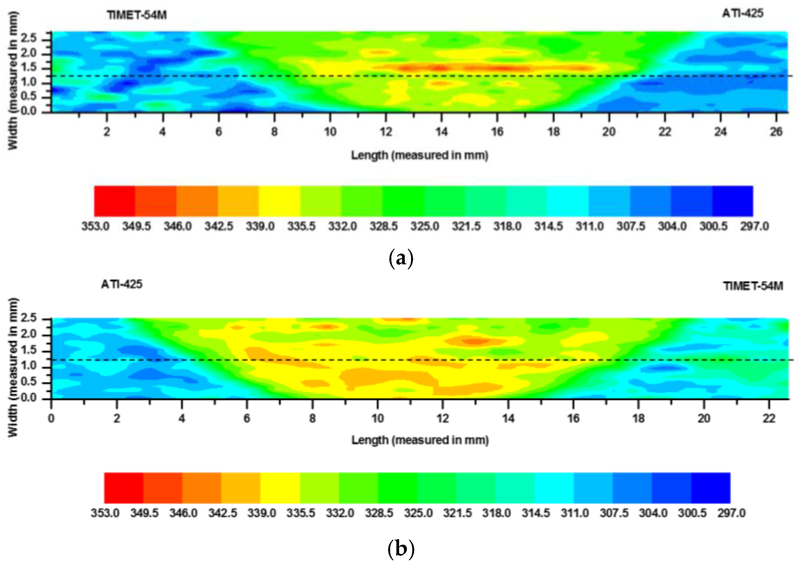
The microhardness contours on the traverse cross section of the weld are shown in the Figure 8. The approximate location of the weld boundaries are identified, however, the width of the TMAZ cannot be determined from the hardness maps. The hardness profiles in the center of each specimen are also plotted in Figure 9. The approximate center line, marked by the dotted line, is the reference line for hardness variations (Figure 9) in the center of the transverse cross-section of the weld.
From the hardness profiles and the maps it can be observed that the hardness values are higher in the WN. A discernible boundary between WN and base material can be observed on either side of the WN. Furthermore, the hardness values in the center of the weld are higher for P4, in comparison with P1. The hardness for TIMET-54M is slightly lower than ATI-425. When plotted on the center of the weld (as shown in the Figure 9), a significant amount of deflection is observed in the hardness values on either side of the WN. A rather uniform hardness profile is observed for P4 in the center of the WN. In both cases the hardness appears to be slightly higher on the retreating side.

3.3. Tensile Specimens

The average yield strength (YS), ultimate tensile strength (UTS), and percent elongation (% Elong.) to failure for four tensile coupons were tested and are shown in Figure 10. From the typical global stress strain data collected for dissimilar FS welds, it can be observed that the values of YS, UTS, and % Elong. for P4 are slightly higher in comparison to P1. The average values of the YS, UTS, and % Elong. are presented in Table 3.

4. Discussion

4.1. Morphology of the Welds

From the macrographs it can be observed that the defect-free welds were made under the adopted processing conditions. A clear distinction of BM, TMAZ (not easily discernible at this level of resolution), and WN can be seen in all of the welds. Based on the macrographs it can be observed that mixing of the material is quite different in the bottom of the weld when TIMET-54M is kept on the advancing side (P4). For the case when ATI-425 is kept on the advancing side (P1), a rather more uniform pattern can been observed. Based on the macrographs it can be deduced that the material flow is primarily dependent on the location of the material; either on the advancing side or on the retreating side.

4.2. Microstructural Evolution

The microstructures evolved in the TMAZ and in the WN are addressed in terms of the grain morphology, phase fractions, and distribution and presence of adiabatic shear bands (ASB). The microstructure in the TMAZ and in the WN are dependent on the total strain, strain rate, stacking fault energy of α (hcp), and β (bcc) phases, and temperature evolving during FSW. During severe plastic deformation imposed by the tapered and tilted tool, a large fraction of the plastic work is converted into heat, and due to low thermal conductivity of the titanium, the heating rate at higher strain rate could be dominating over the heat loss by conduction, resulting in a localized zone of higher temperature, hence, the formation of adiabatic shear bands [39]. The formation of these adiabatic shear bands running across the weld boundary (Figure 7, P1-b1 and P4-c4) is quite distinct in both cases (P1 and P4).

4.2.1. P1: TIMET-54M on the Retreating Side

ImageJ analysis, shown in Figure 11, of the BM of TIMET-54M and ATI-425, has shown that TIMET-54M has slightly higher β content (43%–45%) and, hence, a lower α content, in comparison with ATI-425 (38%–39%). For the case of P1 (see Figure 7a1–g1) when TIMET-54M is present on the retreating side, a severe plastic deformation, along with slightly lower temperature in comparison with the advancing side is experienced. Due to this, a significant amount of α (without being transformed into β) is sheared and migrating from the retreating side in the form of untransformed band of α along the WN, Figure 7b1. As we approach closer to the weld center, c1, a significant amount of the grain boundary α with a rather coarser acicular α has been observed adjacent to the prior β grain boundaries containing a fine acicular α. At the center of the weld d1, and at e1 where temperatures are rather uniform, the cooling rate also appears to be quite adequate in the proximity of the center resulting in a basket-weave morphology, with a grain boundary α with coarser acicular α in the prior β grains. The region which is closer to the advancing side, e1, is significantly deformed, however, unlike the retreating side, no crescent-like structure has been formed on the advancing side. The microstructure at e1 is quite similar to that observed at d1, due to nearly similar temperature profiles. The microstructure at f1, which is closer to ATI-425, and on the advancing side, results in refined α grains in a matrix of β, suggesting that, even on the advancing side, the temperature are not par β transus of ATI-425 (β transus temperature of ATI-425 is 1780 °F).
Briefly, for this case it can be summarized that the region which appears darker in the macrographs in the WN contains prior β grains and fine acicular α. The lighter region, on the other hand, consists of grain boundary α with coarser acicular α in β. Based on the observation it can be concluded that heating rates at high strain rate and cooling rate (by conduction, and by constant argon gas flow) are sufficient enough to avoid formation of any localized heatsink in the WN, hence, resulting in a rather uniform microstructure (grain boundary α with acicular α in β). However, on the retreating side, some regions of α remain untransformed suggesting a sub-β transus temperature profile in that region.

4.2.2. P4: ATI-425 on the Retreating Side

For this case, Figure 7a4–g4, as can be observed that due to the higher β transus temperature of the ATI-425 (1780 °F ± 25 °F (971 °C ± 14 °C)) in comparison with TIMET-54M (1720 °F–1770 °F (938 °C–966 °C)), the crescent-like structure is not formed in the proximity of the weld boundary on the retreating side. The microstructural observation suggests that only refined α grains in β matrix have been observed, at b4. As we move closer to WN inside the weld, at c4, most of the α that is being migrated from the retreating side (ATI-425), due to the higher β transus, is untransformed and appears as a wider streak. In the center of the weld, d4, a chaotic mixing pattern is observed, due to which the top section of weld microstructure (d4) results in the formation of coarser acicular α in β grains that are delineated with grain boundary α. The bottom section of the of the WN microstructure results in the formation of prior β grains with fine acicular α. The microstructure inside the WN close to the weld boundary on the advancing side, at e4, results in coarser acicular α in β. This can be attributed to the fact that although the temperature profiles are nearly similar, due to differences in the β transus temperature and the cooling rates (faster cooling rates at the bottom) the bottom of the weld has finer acicular α and, at e4, rather coarser acicular α has been observed. It can be said that d4, and e4 are mainly made of TIMET-54M. The boundary on the advancing side is severely deformed and due to temperatures reaching on par with the β transus, refined and sheared equiaxed α grains have been observed along with β grains delineated with grain boundary α.
As a general observation, by looking at the microstructures of both cases, it can be said that temperatures on the retreating side are slightly lower due to the tangential vector of the tool rotation and the axial vector of the traverse direction being in the opposite directions. As a result of rather slightly lower temperatures on the retreating side, the material with lower β transus temperature (TIMET-54M) has resulted in the evolution of a Widmanstätten microstructure with fine acicular α in the transformed β grains at the weld boundary. Although, material with higher β transus temperature (ATI-425) resulted in the deformation of α grain at the boundary, yet, as we approach closer to the WN, a similar microstructure (untransformed α, and grain boundary α with acicular α) has been observed. For the combination of alloys considered in this study it is safe to assume that although temperatures on the retreating side are lower than the advancing side, they are still sufficient enough for reaching above the β transus for TIMET-54M and not for ATI-425.

4.3. Microhardness

From Figure 8, it can be seen that TIMET-54M has shown relatively higher hardness in comparison with ATI-425 for BM; the reason being, the base material microstructure of the TIMET-54M contains equiaxed α grain presenting a higher flow stress in comparison with the ATI-425, where α is infused with primary β. Hardness in the WN increases for both cases. The hardness values are significantly fluctuating inside, and around, the WN. In the case of P1, when TIMET-54M, with a lower β transus temperature, was kept on the retreating side, the increase in the hardness on the boundary of the retreating side is a result of finer acicular α in refined prior β grains in comparison with refined α grains on the advancing side of P1. The higher values of hardness on the retreating side for P1 are in correspondence with the microstructure observed (Figure 7b1). Upon close inspection one can observe a very distinctive fine streak in the center of the weld in the macrograph of P1 (Figure 5). The higher values of hardness in that region are also observed in Figure 8a.
For the case of P4, when ATI-425 was kept on the retreating side, the increase in the hardness at the boundary on the retreating side is marked by the grain refinement indicating that temperatures produced on the retreating side have not crossed the β transus of ATI-425; rather, the microstructure is severely deformed into refined equiaxed α grains. As we move closer to the weld center, the temperatures increase, and an increase in the hardness values is registered by the evolution of the finer acicular α in the β grains. At the bottom of the specimen there appears a significant variation in the hardness values owing to the prominent mixing of the two alloys and the formation of refined β grains with finer acicular α in it (Figure 7d4). Based on the hardness pattern the following can be concluded:
(1)
If a material with lower β transus is kept on the retreating side, this results in the formation of a Widmanstätten microstructure with coarser α lamellae for most of the WN and slightly lower hardness values.
(2)
If a material with higher β transus is kept on the retreating side, an increase in the hardness values on the retreating side is marked by the deformation of the α phase. In the weld center the microstructure mostly consists of a basket-weave morphology with finer α lamellae. As we approach the boundary on the advancing side, the hardness increase is a result of both grain refinement and of acicular α in prior β grains.
(3)
As such, no uniformity can be conformed based on the evolution of the microstructure but, for the case of P4, higher values of hardness have been observed on the retreating side suggesting that grain refinement is more dominant in comparison with the finer acicular α formation.

4.4. Mechanical and Microstructural Relationship

From tensile data, as plotted in Figure 10, extracted from global stress strain curves for four specimens of each case, it can be observed that P4, when ATI-425 is on the retreating side, showed higher values of YS and UTS in comparison to P1, when TIMET-54M is on the retreating side. In all of the cases, out of four specimens tested for the analysis, the fracture always occurred on the retreating side. For the case of P4, where the hardness in the WN is slightly higher in comparison with that of P1, it can be said that residual stresses are slightly more compressive [40] giving rise to higher values of YS and UTS. The residual stresses are not measured, however, due to migration of the elements, Al, V, and Fe, the titanium atoms in the bcc (β) and hcp (α) phases are replaced by these elements causing the shrinkage or expansion of the lattice spacing. Further research with transmission electron microscopy (TEM) needs to be done in order to confirm the results as presented during our findings in order to verify the detailed phase transformation and the true nature of deformation. As it appears from the microstructure, it can also be said that if a titanium alloy of lower β transus is kept on the advancing side (P4, in our case, with TIMET-54M on the advancing side) it results in the formation of a basket-weave morphology (refined β grains with finer acicular α) inside the WN that, as a part of entire gage length (if measured in a transverse tensile test for global stress strain curve), assists in achieving superior values of mechanical properties.

5. Conclusions

In the present study, we have successfully joined two dissimilar titanium alloys, ATI-425 and TIMET-54M, with FSW at 300 rpm and 75–100 mm/min traverse speed by using W-La tool with a specified geometry. Weld joints with no visible defects (as shown in Figure 5) were obtained by exchanging the locations (advancing or retreating) of the sheets. The following conclusions were drawn:
(1)
The typical microstructure as it evolved inside, and around, the WN, is dependent on the initial BM microstructure. If a material with a lower β transus temperature (TIMET-54M) is kept on the advancing side(P4), the majority of the microstructure inside the WN is characterized by the refined prior β grains and finer acicular α. On the other hand, if same material with a lower transus temperature (TIMET-54M) is kept on the retreating side (P1), the microstructure in the WN is characterized by coarser α lamellae with grain boundary α.
(2)
Higher values of hardness have been observed for the case when TIMET-54M was kept on the advancing side (P4).
(3)
The global stress strain curve showed an increase in the mechanical properties when TIMET-54M was kept on the advancing side.
A trivial conclusion that can be drawn from this study is that when a titanium alloy with a lower β transus temperature is kept on the advancing side it results in better mechanical properties. However, further study needs to be conducted in order to confirm the concluding remarks.

Acknowledgments

We sincerely thank The Boeing Company for financial support of Titanium Component Manufacturing Research Project at University of Washington. The Boeing Company for support & encouragement.

Author Contributions

Daniel G. Sanders’s lab produced the welded samples, Kapil Gangwar and Andrew Cantrell conducted the experiments and microstructural evaluation. M. Ramulu, Kapil Gangwar analyzed the data in consultation with Daniel G. Sanders and contributed to writing and editing the manuscript.

Conflicts of Interest

The authors declare no conflict of interest.

References

  1. Thomas, W.M.; Nicholas, E.D.; NeedHam, J.C.; Murch, M.G.; Templesmith, P.; Dawes, C.J. Friction Stir Welding; The Welding Institure: Cambridge, UK, 1991. [Google Scholar]
  2. Boyer, R.R. An overview on the use of titanium in the aerospace industry. Mater. Sci. Eng. Struct. Mater. Prop. Microstruct. Process. 1996, 213, 103–114. [Google Scholar] [CrossRef]
  3. Peters, J.O.; Lutjering, G. Comparison of the fatigue and fracture of alpha plus beta and beta titanium alloys. Metall. Mater. Trans. Phys. Metall. Mater. Sci. 2001, 32, 2805–2818. [Google Scholar] [CrossRef]
  4. Lutjering, G. Influence of processing on microstructure and mechanical properties of (alpha + beta) titanium alloys. Mater. Sci. Eng. Struct. Mater. Prop. Microstruct. Process. 1998, 243, 32–45. [Google Scholar] [CrossRef]
  5. Kim, J.S.; Kim, J.H.; Lee, Y.T.; Park, C.G.; Lee, C.S. Microstructural analysis on boundary sliding and its accommodation mode during superplastic deformation of Ti-6Al-4V alloy. Mater. Sci. Eng. Struct. Mater. Prop. Microstruct. Process. 1999, 263, 272–280. [Google Scholar] [CrossRef]
  6. Fonda, R.W.; Knipling, K.E. Texture development in near-alpha Ti friction stir welds. Acta Mater. 2010, 58, 6452–6463. [Google Scholar] [CrossRef]
  7. Fonda, R.W.; Knipling, K.E. Texture development in friction stir welds. Sci. Technol. Weld. Join. 2011, 16, 288–294. [Google Scholar] [CrossRef]
  8. Pao, P.S.; Fonda, R.W.; Jones, H.N.; Feng, C.R.; Moon, D.W. Fatigue crack growth in friction stir welded Ti-5111. In Friction Stir Welding and Processing V; Rajiv, M.W.M., Mishra, S., Lienert, T.J., Eds.; TMS (The Minerals, Metals & Materials Society): Warrendale, PA, USA, 2009. [Google Scholar]
  9. Reynolds, A.P.; Hood, E.; Tang, W. Texture in friction stir welds of Timetal 21S. Scr. Mater. 2005, 52, 491–494. [Google Scholar] [CrossRef]
  10. Yoon, S.; Ueji, R.; Fujii, H. Microstructure and texture distribution of Ti-6Al-4V alloy joints friction stir welded below beta-transus temperature. J. Mater. Process. Technol. 2016, 229, 390–397. [Google Scholar] [CrossRef]
  11. Zhang, Y.; Sato, Y.S.; Kokawa, H.; Park, S.H.C.; Hirano, S. Stir zone microstructure of commercial purity titanium friction stir welded using pcBN tool. Mater. Sci. Eng. Struct. Mater. Prop. Microstruct. Process. 2008, 488, 25–30. [Google Scholar] [CrossRef]
  12. Zhang, Y.; Sato, Y.S.; Kokawa, H.; Park, S.H.C.; Hirano, S. Microstructural characteristics and mechanical properties of Ti-6Al-4V friction stir welds. Mater. Sci. Eng. Struct. Mater. Prop. Microstruct. Process. 2008, 485, 448–455. [Google Scholar] [CrossRef]
  13. Zhou, L.; Liu, H.J.; Liu, Q.W. Effect of process parameters on stir zone microstructure in Ti-6Al-4V friction stir welds. J. Mater. Sci. 2010, 45, 39–45. [Google Scholar] [CrossRef]
  14. Zhou, L.; Liu, H.J.; Wu, L.Z. Texture of friction stir welded Ti-6Al-4V alloy. Trans. Nonferr. Met. Soc. China 2014, 24, 368–372. [Google Scholar] [CrossRef]
  15. Edwards, P.; Ramulu, M. Identification of Process Parameters for Friction Stir Welding Ti-6Al-4V. J. Eng. Mater. Technol. Trans. Asme 2010, 132. [Google Scholar] [CrossRef]
  16. Rai, R.; De, A.; Bhadeshia, H.K.D.H.; DebRoy, T. Review: Friction stir welding tools. Sci. Technol. Weld. Join. 2011, 16, 325–342. [Google Scholar] [CrossRef]
  17. Edwards, P.D.; Ramulu, M. Material flow during friction stir welding of Ti-6Al-4V. J. Mater. Process. Technol. 2015, 218, 107–115. [Google Scholar] [CrossRef]
  18. Pilchak, A.L.; Williams, J.C. Microstructure and Texture Evolution during Friction Stir Processing of Fully Lamellar Ti-6Al-4V. Metall. Mater. Trans. Phys. Metall. Mater. Sci. 2011, 42, 773–794. [Google Scholar] [CrossRef]
  19. Edwards, P.; Ramulu, M. Fracture toughness and fatigue crack growth in Ti-6Al-4V friction stir welds. Fatigue Fract. Eng. Mater. Struct. 2015, 38, 970–982. [Google Scholar] [CrossRef]
  20. Edwards, P.; Ramulu, M. Fatigue performance of Friction Stir Welded titanium structural joints. Int. J. Fatigue 2015, 70, 171–177. [Google Scholar] [CrossRef]
  21. Edwards, P.; Ramulu, M. Fatigue performance of Friction Stir Welded Ti-6Al-4V subjected to various post weld heat treatment temperatures. Int. J. Fatigue 2015, 75, 19–27. [Google Scholar] [CrossRef]
  22. Edwards, P.D.; Ramulu, M. Comparative study of fatigue and fracture in friction stir and electron beam welds of 24mm thick titanium alloy Ti-6Al-4V. Fatigue Fract. Eng. Mater. Struct. 2016, 39, 1226–1240. [Google Scholar] [CrossRef]
  23. Sanders, D.G.; Edwards, P.; Cantrell, A.M.; Gangwar, K.; Ramulu, M. Friction Stir-Welded Titanium Alloy Ti-6Al-4V: Microstructure, Mechanical and Fracture Properties. JOM 2015, 67, 1054–1063. [Google Scholar] [CrossRef]
  24. Fazel-Najafabadi, M.; Kashani-Bozorg, S.F.; Zarei-Hanzaki, A. Dissimilar lap joining of 304 stainless steel to CP-Ti employing friction stir welding. Mater. Des. 2011, 32, 1824–1832. [Google Scholar] [CrossRef]
  25. Liao, J.S.; Yamamoto, N.; Liu, H.; Nakata, K. Microstructure at friction stir lap joint interface of pure titanium and steel. Mater. Lett. 2010, 64, 2317–2320. [Google Scholar] [CrossRef]
  26. Ishida, K.; Gao, Y.; Nagatsuka, K.; Takahashi, M.; Nakata, K. Microstructures and mechanical properties of friction stir welded lap joints of commercially pure titanium and 304 stainless steel. J. Alloy. Compd. 2015, 630, 172–177. [Google Scholar] [CrossRef]
  27. Fazel-Najafabadi, M.; Kashani-Bozorg, S.F.; Zarei-Hanzaki, A. Joining of CP-Ti to 304 stainless steel using friction stir welding technique. Mater. Des. 2010, 31, 4800–4807. [Google Scholar] [CrossRef]
  28. Buffa, G.; Baffari, D.; di Caro, A.; Fratini, L. Friction stir welding of dissimilar aluminium-magnesium joints: Sheet mutual position effects. Sci. Technol. Weld. Join. 2015, 20, 271–279. [Google Scholar] [CrossRef]
  29. Yuan, W.; Mishra, R.S.; Carlson, B.; Verma, R.; Mishra, R.K. Material flow and microstructural evolution during friction stir spot welding of AZ31 magnesium alloy. Mater. Sci. Eng. Struct. Mater. Prop. Microstruct. Process. 2012, 543, 200–209. [Google Scholar] [CrossRef]
  30. Chen, Y.H.; Ni, Q.; Ke, L.M. Interface characteristic of friction stir welding lap joints of Ti/Al dissimilar alloys. Trans. Nonferr. Met. Soc. China 2012, 22, 299–304. [Google Scholar] [CrossRef]
  31. Hong, J.K.; Lee, C.H.; Kim, J.H.; Yeom, J.T.; Lee, C.G. Friction Stir Welding of Dissimilar Al 5052 to Ti-6Al-4V Alloy with WC-Co Tool. Steel Res. Int. 2010, 81, 1092–1095. [Google Scholar]
  32. Zhang, Z.H.; Li, B.; Feng, X.M.; Shen, Y.F.; Hu, W.Y. Friction-stir welding of titanium/aluminum dissimilar alloys: Joint configuration design, as-welded interface characteristics and tensile properties. Proc. Inst. Mech. Eng. Part B J. Eng. Manuf. 2014, 228, 1469–1480. [Google Scholar] [CrossRef]
  33. Vaidya, W.V.; Horstmann, M.; Ventzke, V.; Petrovski, B.; Kocak, M.; Kocik, R.; Tempus, G. Structure-property investigations on a laser beam welded dissimilar joint of aluminium AA6056 and titanium Ti6Al4V for aeronautical applications Part I: Local gradients in microstructure, hardness and strength. Mater. Werkst. 2009, 40, 623–633. [Google Scholar] [CrossRef]
  34. Hsieh, C.T.; Chu, C.Y.; Shiue, R.K.; Tsay, L.W. The effect of post-weld heat treatment on the notched tensile fracture of Ti-6Al-4V to Ti-6Al-6V-2Sn dissimilar laser welds. Mater. Des. 2014, 59, 227–232. [Google Scholar] [CrossRef]
  35. Jata, K.V.; Subramanian, P.R.; Reynolds, A.P.; Trapp, T.; Helder, E. Friction stir welding of titanium alloys for aerospace application: Microstructure and mechanical behavior. In Proceedings of the Fourteenth (2004) International Offshore and Polar Engineering Conference, Toulon, France, 23–28 May 2004.
  36. ATI Technical Data Sheet. Available online: https://www.atimetals.com/Documents/ati_425_alloy_tds_en_v5.pdf (accessed on 21 October 2016).
  37. Kosaka, Y.; Gudipati, P. Supreplastic Forming Prperties of TIMETAL 54M. Available online: http://c.ymcdn.com/sites/www.titanium.org/resource/resmgr/2010_2014_papers/KosakaYogi_2010_AerospaceMat.pdf (accessed on 21 October 2016).
  38. Edwards, P.; Ramulu, M. Surface Residual Stresses in Ti-6Al-4V Friction Stir Welds: Pre- and Post-Thermal Stress Relief. J. Mater. Eng. Perform. 2015, 24, 3263–3270. [Google Scholar] [CrossRef]
  39. Lienert, T.J. Microstructure and mechanical properties of friction stir welded titanium alloys. In Friction Stir Welding and Processing; Rajiv, M.W.M., Mishra, S., Eds.; ASM International: Geauga County, OH, USA, 2007; p. 128. [Google Scholar]
  40. Frankel, J.; Abbate, A.; Scholz, W. The Effect of Residual-Stresses on Hardness Measurements. Exp. Mech. 1993, 33, 164–168. [Google Scholar] [CrossRef]
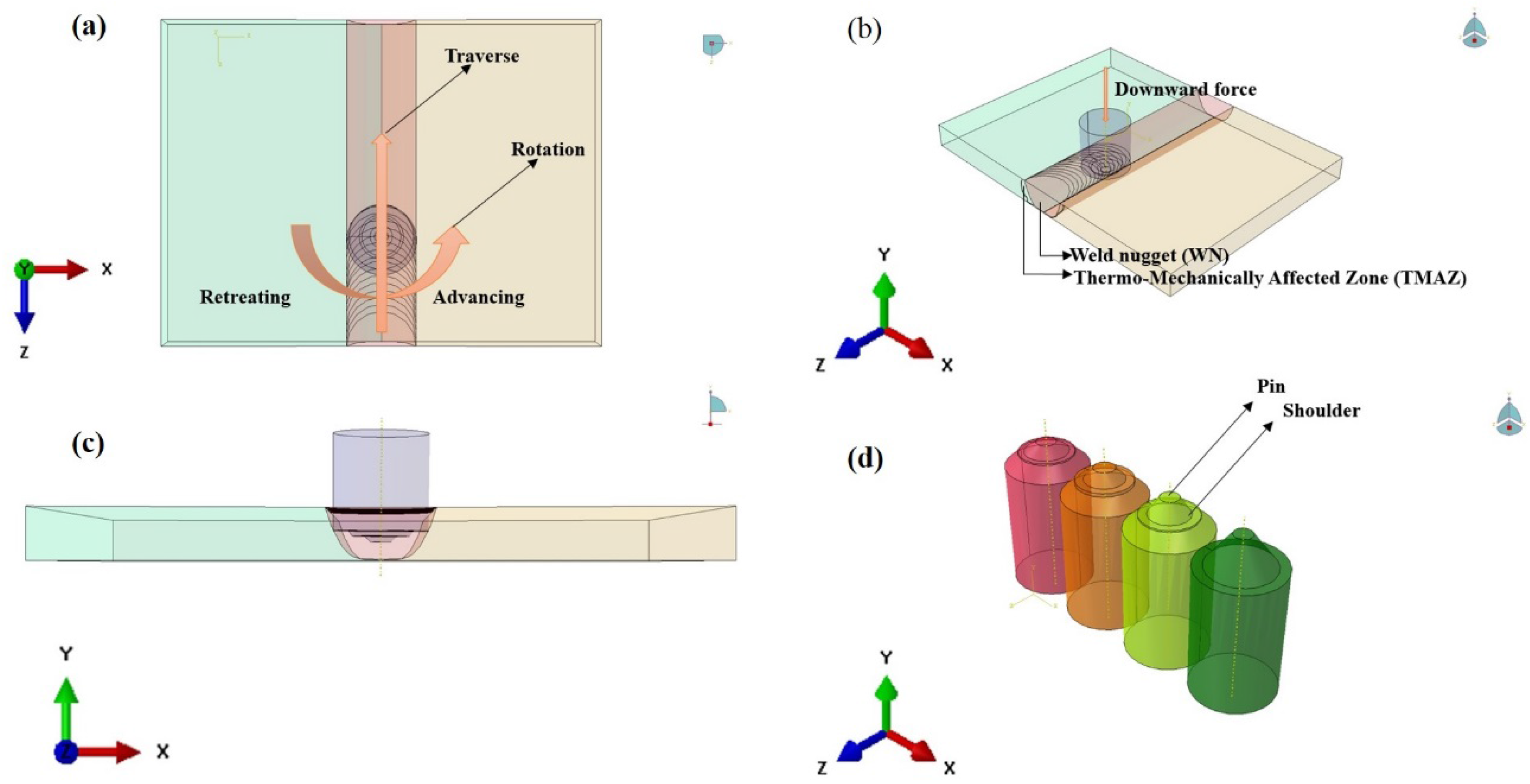
Figure 1. FSW and tool schematics. (a) Top; (b) side; (c) front; (d) tool designs. Images not to scale.
Metals 06 00252 g001
Figure 2. Typical schematic diagram appearance of the sectioned friction stir welded specimen.
Metals 06 00252 g002
Figure 3. (a) Indention pattern on the transverse cross-section of the weld; and (b) distance between two indent at 700× magnification.
Metals 06 00252 g003
Figure 4. Schematic diagram of tensile specimens.
Metals 06 00252 g004
Figure 5. Typical macrographs of butt welds, (P1) ATI-425 on the advancing side, and (P4) TIMET-54M on the advancing side. RET: Retreating; and ADV: Advancing side.
Metals 06 00252 g005
Figure 6. Prescribed locations for the microstructure taken for comparison. a, and g represent base material; b, and f represent TMAZ on RET, and ADV side; c, and e represent locations inside the weld nugget, however, closer to TMAZ on RET, and ADV side; d, represents locations in WN.
Metals 06 00252 g006
Figure 7. Optical microstructure of the specimens, P1 (marked a1 to g1), and P4 (marked a4 to g4). With a1,4 being on the retreating side; and g1,4 being on the advancing side. The reader is recommended to the web version for enhanced clarity of the text. Scale: 20 µm for all the micrographs except c4. For c4, the scale is 10 µm.
Metals 06 00252 g007
Figure 8. Color-coded microhardness profiles on the transverse cross-sections of the weld. (a) P1; and (b) P4.
Metals 06 00252 g008
Figure 9. Hardness profile in the center of the weld.
Metals 06 00252 g009
Figure 10. Tensile test results.
Metals 06 00252 g010
Figure 11. ImageJ analysis of TIMET-54M and ATI-425, for P1. TIMET-54M and ATI-425 have β percentages of 45.3099% and 41.5035%, respectively.
Metals 06 00252 g011
Table 1. Mass fraction (wt. %) composition of the alloys.
Alloyswt. %AlMoVFeOCNHTi
ATI-425Min3.5 21.20.2 Bal.
Max4.5 31.80.30.080.030.015
TIMET-54MMin4.50.430.2 0.015Bal.
Max5.5150.80.20.1
Table 2. Friction stir welding Process parameters adopted in this study.
ParametersValues
Spindle Speed300 rpm
Tool Traverse Speed~75–100 mm/min
Forging Load~15.6 kN
Tool Plunging Depth~1.6 mm
Tool Tilt3° from direction of traverse
Tool MaterialW-La
Tool Pin Length~1.4 mm
Tool Pin Diameter~8.6 mm
Tool Shoulder Diameter~15.9 mm
Table 3. Average tensile test values. Yield strength (YS); Ultimate tensile strength (UTS); percent elongation (% Elong.) and standard deviation (St. Dev.).
SpecimenYS (in MPa)St. Dev. in YS (MPa)UTS (MPa)St. Dev. in UTS (MPa)% Elong.St. Dev. in % Elong.
P1966.4815.87995.6418.296.370.62
P498912.331019.0716.16.570.48