4. Analysis of Results and Discussion
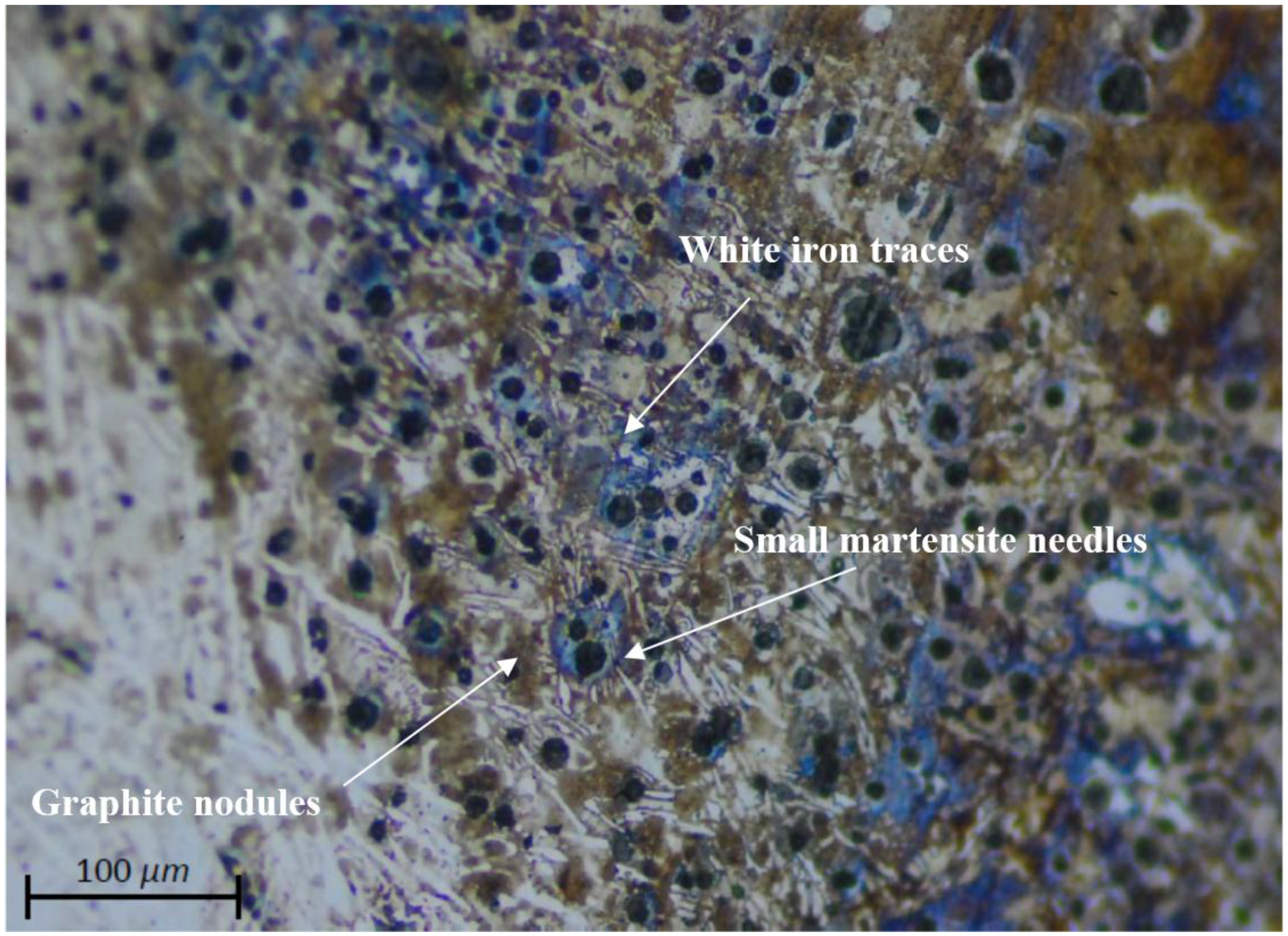
Micrographs of TIG root welds (made with Inconel 625) of the ductile iron test plate following a preheat treatment at 350 °C (but without subsequent annealing treatment) (
Figure 1) reveal in the interface structures formed by traces of white iron in which most of the graphite has combined to form cementite. Very small and uniformly distributed spherulites can also be seen. The rate of cooling also produced martensite precipitates, a partial consequence of the effect of Ni on the dissolution of the carbides being counterbalanced by the effect of Cr as a stabilizer. The Vickers hardness was 460, mostly in areas where the carbides precipitated. The consequence was the beginnings and expansion of a brittle fracture in the zone of the interface. The structure can be defined as a martensite white iron matrix.
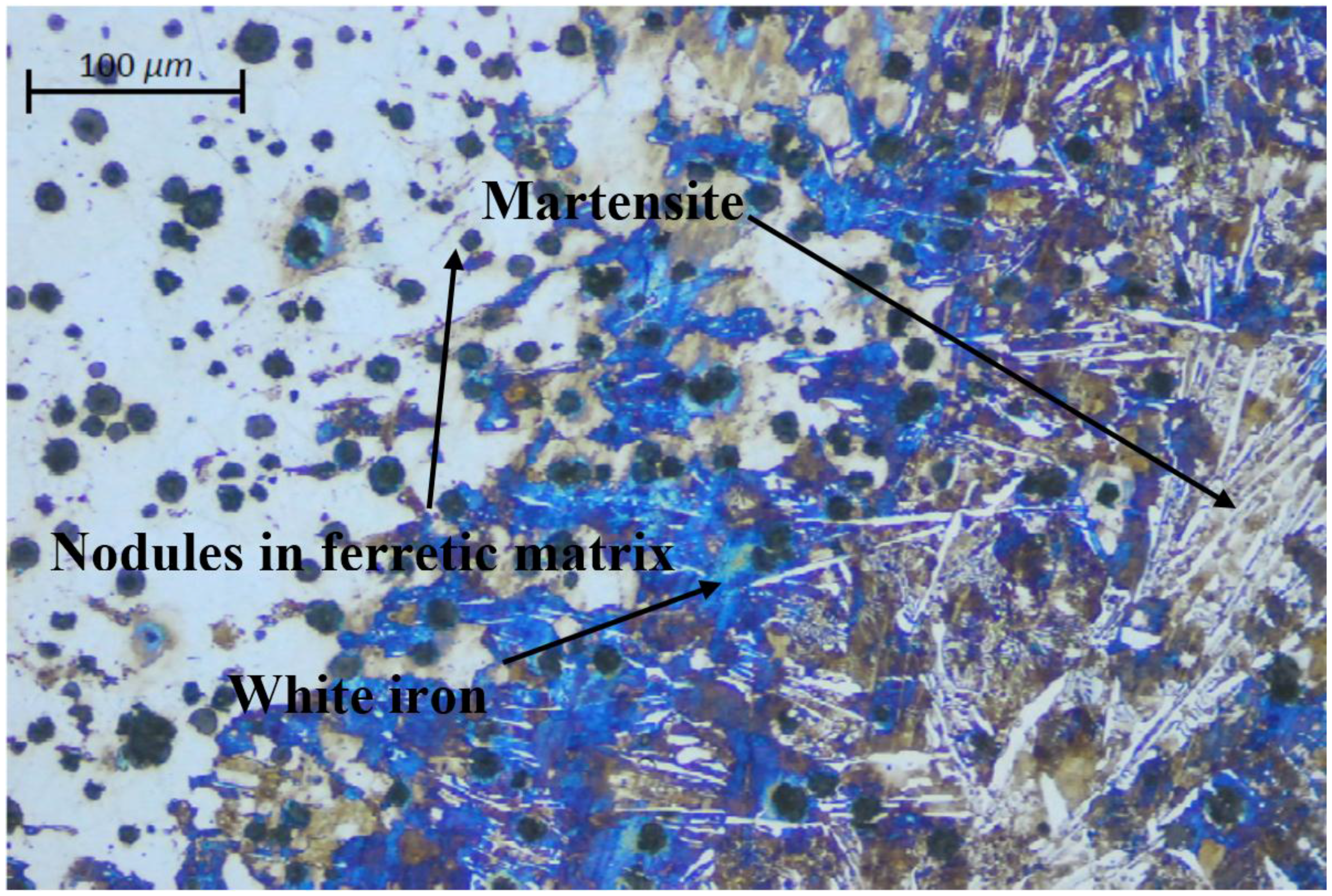
The micrograph shows the manual weld of ductile cast iron using an electrode coated with 97.6% Ni (
Figure 2) made on top of an Inconel root weld. The image reveals a structure in which traces of white iron have significantly diminished, resulting in a higher concentration of nodules of uniformly distributed graphite that are larger than those shown in the previous micrograph. This is largely due to the Ni content of the coated filler electrode, largely preventing the formation of carbides in the dilution zone; however, it is also possible to see martensite precipitate in the austenitic matrix (in which the Vickers hardness is 700 as a result of the rapid cooling of the weld). The fracture has extended in the interface zone, which has become brittle because of the cooling rate.
In a micrograph of a filler weld made with a 97.6% Ni electrode with a maximum dilution of the base material and preheating to 350 °C followed by air cooling (
Figure 3), three zones can be distinguished: weld, base material, and interface [
11,
12].
Ferritic-pearlitic ductile iron can be seen in the vicinity of the base material near the weld. This material does not provide high levels of hardness (360 HV) and becomes more similar to the base material in hardness as we move away from the area affected by heat. At the interface of the weld, we can see martensite precipitates tempered in a ferrite matrix (as a result of the Ni content in the filler metal) with slight traces of cementite and graphite nodules (smaller than those in the casting) that are uniformly distributed over the entire zone. The hardness produced at this stage is greater than the base metal. In the region of the weld, the graphite appears as nodules that are smaller than those in the interface and evenly distributed across the weld. The hardness is lesser than that obtained in the interface, and fractures occur in the weld zone near the brittle interface.
In the micrograph of the base material (
Figure 4), structural formations of material near the weld and at the boundary of the heat affected zone can be seen. These ferriticpearlitic structures contain uniform nodules that are larger than those visible in the micrographs of the interface between the filler material and the ductile iron. These structures are uniformly distributed and similar to the structures of the material from which the test plates are made albeit generally harder.
The micrograph (
Figure 5) shows the formation of nodules in the weld made with filler material applied with a 97.6% Ni electrode where a uniform distribution of ferritic material and traces of retained austenite can be found with sizes smaller than those found on the base material. A distribution similar to that shown above can be found in the structure on the Inconel 625 filler material used in the root weld.
A transformation of the ferrite structure in the interface near the metal base can be seen in the micrograph of the weld obtained with a 97.6% Ni coated electrode on ductile iron in the filler zone on the second pass—and with subsequent heat treatment at 900 °C (
Figure 6). The transformation is a consequence of thermal annealing and the increased Ni in the filler. This implies a considerable reduction in the strength of the material and an increase in the elongation at fracture with respect to the filler metal (in which nodules that are smaller than those in the interface are precipitated) [
13,
14] and the base metal where the hardness is lesser than samples made without preheating. The fracture is more ductile than in the previous cases and usually occurs in the cast zone near the interface [
15].
In the micrograph of the interface of the ductile iron TIG root weld made with an Inconel 625 electrode and preheating to 350 °C and with subsequent annealing treatment at 900 °C (
Figure 7), it can be seen that, despite the heat treatment, small traces of white iron in a martensitic matrix remain undissolved. Vickers hardness levels of 600 are produced—this being below the levels obtained using air cooling because the Cr content in the Inconel has retained part of the carbides formed in the weld. The illustration shows a higher amount of graphite nodules that are smaller than those found in the air-cooled base material. The fracture was brittle in this zone and started at the interface.
The emergence of iron carbide (cementite) is influenced by the speed of cooling metastable, while Ni (nickel) is an gammageno element, which prevents the formation of carbides, given the amount of carbon present in the composition smelting, and added to the fast cooling of the welding speed, resulting in the precipitation of carbides of iron that can later be dissolved with annealing heat treatments.
The left part of the micrograph (
Figure 8) shows that, after the annealing step, the ductile iron passed from ferritic-pearlitic ductile iron to ferritic iron with slightly larger and uniformly distributed nodules. The hardness is less than the original casting but with greater elongation at fracture. The micrograph on the right shows a uniform distribution of spherulites in the weld filler metal, and these are smaller in the ferrite matrix as a consequence of the Ni content and the furnace cooling rate.
Manual arc welding with an electrode of 97.6% Ni is straightforward, the weld not being excessively fluid and high levels of carbide formation not occurring. Hardness is considerably less than that obtained in the root weld made with an Inconel source rod, although mechanical properties are acceptable and there is greater elongation at fracture. Micrographs show that an annealing treatment caused the martensitic structures to disappear and dissolved the traces of white iron producing a structure of nodular graphite on top of the ferrite matrix with an increased level of deformability [
16,
17,
18].
Fractures according to the type of weld are shown in
Figure 9.
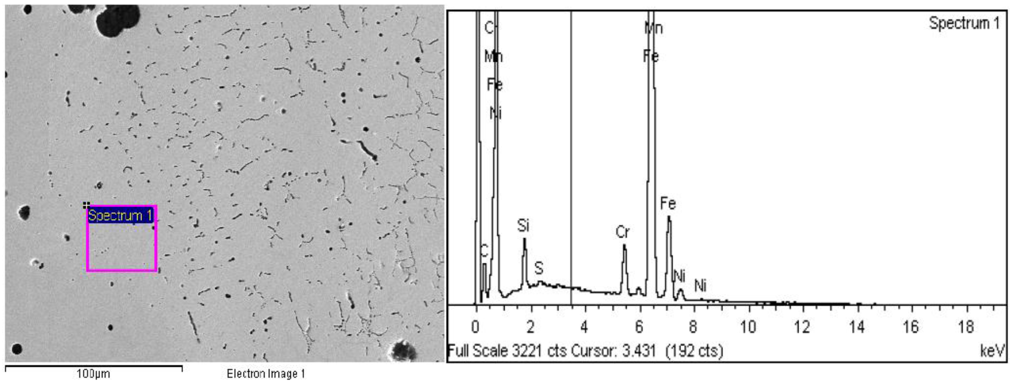
The scanning electron microscopy (SEM) in
Figure 10 shows the interface zone in the root weld applied with Inconel 625 but without heat treatment.
Figure 11 shows the filler weld made with two passes of a 97.6% Ni coated electrode without treatment and the corresponding spectra.The spectrum in
Figure 10 shows a high amount of chromium in the weld interface and the root weld where an Inconel 625 electrode was used—which influenced the formation of carbide precipitates that give rise to traces of white iron. The effect was to increase hardness and counteract the effect of Ni, as can be observed in the micrograph obtained for this zone in
Figure 1. Another effect is the production of the beginnings of brittle fractures and a progressive growth of fractures in response to traction and bending.
The spectrum shown in
Figure 11 corresponds to the interface of the first filler pass (97.6% Ni electrode) on the root pass weld (made using an Inconel 625 electrode). A remarkable decrease in the Cr content can be observed in the spectrum, causing a substantial decrease in traces of white iron and a greater influence of Ni on the structure (causing a decrease in hardness). A fracture initiated by bending and traction expands through the interface zone—as can be seen in the corresponding optical micrograph shown in
Figure 2.
The SEM images in
Figure 12 basically show the interface zone of the weld applied in the second filler pass with a 97.6% Ni electrode over the weld applied in the first pass (97.6% Ni) with subsequent annealing.
Figure 13 shows the root weld on the same plate applied with Iconel 625 and annealed at 900 °C and the corresponding spectra.
The spectrum shown in
Figure 12 corresponds to the second pass of the filler electrode (97.6% Ni) and annealing treatment at 900 °C with furnace cooling. We can observe a virtual absence of Cr, which directly influences the structure of the welding interface: dissolving the carbides and producing an absence of white cast iron and a substantial decrease in hardness. The result is a greater elongation at fracture. The graphite is precipitated in a fully nodular form, and the ferriticmatrix can be seen in the optic micrograph in
Figure 6. Tensile and bending fracture occurs in this zone near to the base material.
The spectrum shown in
Figure 13 corresponds to the interface of the root weld applied with an Inconel 625 rod and an annealing treatment at 900 °C and furnace cooling. The spectrum shows a decrease in Cr that is less pronounced than in the specimen with no heat treatment. The result is a partial reduction in carbides as a consequence of incomplete dissolution through heating and the speed of furnace cooling. As a consequence, there is a reduction in hardness at the interface although it remains very hard (as can be seen in the optical micrograph in
Figure 7). The result is a substantial increase in strain capacity, although the fracture is brittle and starts in the root zone.
Acknowledgments
We would like to give thanks to Language Translators Service of the Languishes Department of UniversitatPolitècnica de València, Spain.
Author Contributions
In this investigation, F.J.C.-C. and M.P.-G. conceived and designed the experiments; F.J.C.-C., R.P.-M., and M.A.P.-P. performed the experiments; F.J.C.-C., R.P.-M., and M.P.-G. analyzed the data; M.A.P.-P. contributed materials/analysis tools; F.J.C.-C. and M.P.-G. wrote the paper.
Conflicts of Interest
The authors declare no conflict of interest.
References
- Apraiz, J. Fundiciones; Editorial Dossat: Madrid, Spain, 1981; pp. 144–145. [Google Scholar]
- Eutectic Castolin: Practice Handbook (Spanish Edition); Castolin: Madrid, Spain, 1993.
- Huke, E.E.; Udin, H. Welding Metallurgy of Nodular Cast Iron. Weld. J. 1953, 32, 378s–385s. [Google Scholar]
- Zhang, X.Y.; Zhou, Z.F.; Zhang, Y.M.; Wu, S.L.; Guan, L.Y. Influence of nickel-iron electrode properties and joint shapes on welded joint strength of pearlitic nodular iron. Weld. J. Incl. Weld. Res. Suppl. 1996, 75, 280s. [Google Scholar]
- Pease, G.R. The Welding of Ductile Iron. Weld. J. 1960, 39, 1–9. [Google Scholar]
- Nonast, R. SoldeoElectrico Manual al Arco Metálico; Gráficas Summa: Madrid, Spain, 1973; p. 84. [Google Scholar]
- Fatahalla, N.; Bahi, S.; Hussein, O. Metallurgical parameters, mechanical properties and machinability of ductile cast iron. J. Mater. Sci. 1996, 31, 5765–5772. [Google Scholar] [CrossRef]
- Manual de Utilización; CastolinEspaña: Madrid, Spain, 1993; p. 64.
- Jeshvaghani, R.A.; Jaberzadeh, M.; Zohdi, H.; Shamanian, M. Microstructural study and wear behavior of ductile iron surface alloyed by Inconel 617. Mater. Des. 2014, 54, 491–497. [Google Scholar] [CrossRef]
- Steglich, D.; Brocks, W. Micromechanical modelling of the behaviour of ductile materials including particles. Comput. Mater. Sci. 1997, 9, 7–17. [Google Scholar] [CrossRef]
- Pascual, M.; Cembrero, J.; Salas, F.; Martínez, M.P. Analysis of the weldability of ductile iron. Mater. Lett. 2008, 62, 1359–1362. [Google Scholar] [CrossRef]
- Cembrero, J.; Pascual, M. Soldabilidad de las fundiciones de grafitoesferoidal. Rev. Metal. 1999, 35, 392–401. [Google Scholar] [CrossRef]
- El-Banna, E.M.; Nageda, M.S.; El-Saadat, M.M.A. Study of restoration by welding of pearlitic ductile cast iron. Mater. Lett. 2000, 42, 311–320. [Google Scholar] [CrossRef]
- El-Banna, E.M. Effect of preheat on welding of ductile cast iron. Mater. Lett. 1999, 41, 20–26. [Google Scholar] [CrossRef]
- Bayati, H.; Elliott, R. Influence of matrix structure on physical properties of an alloyed ductile cast iron. Mater. Sci. Technol. 1999, 15, 265–277. [Google Scholar] [CrossRef]
- Seferian, D. Las Soldaduras: Técnica y Control; Editorial Urmo.: Bilbao, Spain, 1965; pp. 295–299. [Google Scholar]
- Kiser, S.D.; Faws, P.E.; Northey, M. Welding Cast Iron: Straightforward. Can. Weld. Assoc. J. 2005, 1–4. Available online: http://selector.specialmetalswelding.com/publica/cwafall2005.pdf (accessed on 18 November 2016). [Google Scholar]
- Pouranvari, M. On the Weldability of Grey Cast Iron Using Nickel Based Filler Metal. Mater. Des. 2010, 31, 3253–3258. [Google Scholar] [CrossRef]
Figure 1.
Micrograph of the ductile iron tungsten inert gas (TIG) root weld using Inconel 625 and without subsequent annealing.
Figure 2.
Micrograph of ductile iron weld using 97.6% Ni coated electrode on an Inconel root weld without heat treatment.
Figure 3.
Micrograph of a weld performed with a 97.6% Ni electrode on a ductile iron casting with heat treatment at 350 °C and air cooling.
Figure 4.
Micrograph of the structure produced on the base material at the edge of the heat affected zone.
Figure 5.
Micrograph of the material deposited on the ductile iron weld.
Figure 6.
Micrograph of the filler zone in a ductile iron weld using a 97.6% Ni coated electrode with subsequent thermal annealing at 900 °C.
Figure 7.
Micrograph of a root weld in ductile iron made with Inconel 625 and subsequent heat treatment at 900 °C.
Figure 8.
Micrographs of ductile iron showing the distribution of the nodules on the weld after annealing at 900 °C.
Figure 9.
Zones of metallographic observation: (A) weld base metal base interface, (B) weld bead, (C) base metal.
Figure 10.
A SEM image and micrograph of the interface zone in a root weld without heat treatment and where a high amount of Cr can be observed in zones welded with Inconel.
Figure 11.
SEM and micrograph of the weld interface with filler applied using a 97% Ni electrode without subsequent heat treatment. Note the low Cr content.
Figure 12.
This figure shows micrographic and spectrum images of the filler weld interface of the top pass (electrode 97.6% Ni) and with a heat treatment at 900 °C. A higher content of free carbon is observed due to the dissolution of the white iron traces, while Cr is barely detectable (meaning greater ductility and less hardness).
Figure 13.
Micrograph and SEM taken at the root weld interface (Inconel 625) with annealing at 900 °C that shows a continuing high Cr level. The hardness level is high but lower than without heat treatment although the structure remains brittle.
Table 1.
Alloying elements of ductile cast iron.
| Cast | %C | %Si | %Mn | %S | %P | %Ni | %Cu | %Cr | %Mo | %Mg |
|---|
| Ductile | 3.71 | 2.54 | 0.04 | <0.01 | 0.02 | 0.02 | 0.026 | 0.03 | <0.01 | 0.03 |
Table 2.
Mechanical properties of ductile cast iron.
| Mechanical Characteristics | Values |
|---|
| Tensile strength (MPa) | 370 |
| Yield strength (MPa) | 320 |
| Elongation (%) | 6 |
| Elastic modulus (MPa) | 160,000 |
| Brinell hardness | 190 |
| Fatigue limit (MPa) | 280 |
Table 3.
Electrodes used for ductile iron welds.
| Electrode | Composition |
|---|
| Element | % |
|---|
| Inconel 625 | Si | 0.5 |
| Mn | 0.5 |
| Ni | 58 |
| Cr | 20–25 |
| Nb | 3.5 |
| Ta | 4.5 |
| Mo | 8–10 |
| Fe | Other |
| Ni 97.6% | C | <0.1 |
| Si | <0.4 |
| Mn | 0.20 |
| Ni | 97.61 |
| Fe | Other |
Table 4.
Mechanical properties of the ductile iron welds.
| Welding | Rod | S (MPa) | YS (MPa) | A% | HV Interface | HV Welding | HV HAZ |
|---|
| Pre-heating 350 °C and air cooling | Inconel 625 root | 320 | 310 | 5.5 | 730 | 510 | 295 |
| Ni 97.6% filler | 490 | 191 |
| Pre-heating 350 °C and annealed at 900 °C | Inconel 625 root | 300 | 285 | 7 | 610 | 400 | 210 |
| Ni 97.6% filler | 230 | 160 |
© 2016 by the authors; licensee MDPI, Basel, Switzerland. This article is an open access article distributed under the terms and conditions of the Creative Commons Attribution (CC-BY) license (http://creativecommons.org/licenses/by/4.0/).


 ,
, 


