Article

Tool Wear Characteristics and Effect on Microstructure in Ti-6Al-4V Friction Stir Welded Joints

by
Ameth Fall
1,*,
Mostafa Hashemi Fesharaki
2,
Ali Reza Khodabandeh
2 and
Mohammad Jahazi
1,*
1
Ecole de Technologie Supérieure (E.T.S), Département de Génie Mécanique, 1100 Rue Notre-Dame Ouest, Montréal, QC H3C 1K3, Canada
2
Science and Research Branch, Islamic Azad University, Hesarak, Teheran 982100, Iran
*
Authors to whom correspondence should be addressed.
Metals 2016, 6(11), 275; https://doi.org/10.3390/met6110275
Submission received: 24 September 2016 / Revised: 3 November 2016 / Accepted: 4 November 2016 / Published: 10 November 2016

Abstract

:
In the present paper, tool wear and the rate of wear during friction stir welding (FSW) of Ti-6Al-4V alloy are investigated. A conical tungsten carbide tool was used to produce butt-type friction stir welded joints in two-millimeter thick Ti-6Al-4V sheets. An original design of a movable pin allowed for the examination of the tool damage for each process condition. The influence of tool degradation on the quality of the welded joints and the damage brought to the microstructure are examined and discussed. For this purpose, optical and scanning electron microscopies as well as EDX analyses were used to examine the tool wear and the resulting macrostructures and microstructures. The type and nature of the defects are also analyzed as a function of FSW processing parameters. Important geometry and weight variations were observed on the pin and shoulder for all welding conditions, in particular when low tool rotation and travel speeds were used. Experimental results also show that the radial wear of the pin is not uniform, indicating the presence of important frictional temperature gradients through the thickness of the joint. The maximum wear was measured at a location of about one millimeter from the pin root center. Finally, tool rotation was determined as the most significant process parameter influencing both tool wear and microstructure of the joints.

1. Introduction

Manufacturing of structural components made of welded Ti-alloy sheets or thin plates is continuously increasing in the transportation and energy industries mainly because these alloys possess an excellent combination of low-density, superior mechanical properties along with high corrosion and erosion resistance. Fusion welding techniques such as tungsten inert gas (TIG) or laser are extensively used to join titanium alloys. However, the formation of a brittle cast structure, residual stresses, and undesirable deformation limits their applications to critical structural components [1,2]. Friction stir welding (FSW) as a solid state welding process is one of the most promising techniques for joining sheets and thin plates made of titanium alloys, avoiding a large number of difficulties arising from the use of fusion welding processes, and could be used for the manufacturing of large size components for aerospace applications [3,4,5,6]. Moreover, FSW could also be used as an alternative manufacturing technology for the fabrication of hollow components made of Ti alloys which are traditionally produced by a combination of diffusion bonding and superplastic forming [7,8]. Details regarding the principles of the FSW process are well discussed in other publications [6,7].
While FSW has been extensively used for joining light alloys such as Al and Mg, very few reports are available on the application of the technique to titanium alloys. The main difficulty arises from the challenges related to FSW tool material. The high mechanical strength and low thermal conductivity of titanium results in very high frictional forces and heat generation at the tool-workpiece interface, thereby limiting possible tool materials compared with Al or Mg alloys [8]. In the case of Al and Mg alloys, due to their low strength and melting points, the welding tool is commonly made of tool steel [9,10,11]. In contrast, the situation is different for high strength materials such as titanium alloys as their high strength and high melting point do not allow use of tool steels for FSW. Specifically, the tool material should maintain enough strength, to deform and stir the alloy, be resistant to fatigue, fracture and mechanical wear, as well as inert to chemical reactions with both the weld material and the atmosphere at temperatures higher than 1000 °C, which is not the case for any tool steel. Tungsten-based alloys have been used as tool and pin materials for FSW of nickel-aluminum alloys and titanium alloys. Sanders et al. [5] and Farias et al. [12] recommended four tungsten alloys as tool materials: WC, W-25%Re, Densimet and W-1%LaO2, while others have recommended TiC or polycrystalline boron nitride (pcBN) [13,14].
Indeed, even with such refractory materials, tool wear is still a major issue and its influence on microstructure damage, and hence, weld quality, is of prime importance. However, few data is available on tool wear during FSW with most of the publications being focused on steel and aluminum alloys [15,16]. For example, Park et al. and Yutaka et al. [17,18] conducted a detailed study on the tool wear in FSW stainless and ferritic steel welds using pcBN and Co tools, respectively. They reported that Cr-rich borides were formed at the interface between the workpiece and the pcBN tool, resulting in significant mechanical/chemical wear. Also, Weinberger et al. [16] reported that tools made of Rhenium (Re) and W-based Rhenium alloys (e.g., 25% Re + W) show very similar performance characteristics to that of pcBN. Zhang et al. [19] reported wear of pcBN tool during FSW of pure Ti and indicated that pcBN might have reacted with Ti. However, no details were provided on the influence of the FSW parameters on tool wear and the nature of the wear products.
Among the above tool materials, WC is the most cost effective with relatively good machinability and chemical stability. However, the influence of processing parameters during FSW of Ti-alloys on WC tool damage and its impact on microstructural changes and defect generation have not been quantified. In the present work, two-millimeter thick Ti-6Al-4V sheets were friction stir welded using a WC tool. The tool wear characteristics and its evolution are analyzed and discussed in relation to FSW process parameters (tool rotational and travel speeds), temperature gradients and different frictional conditions in the joint. Microstructural damages and changes in relation to the evolution of tool wear are also analyzed and discussed. The impact of each process parameter on wear rate is quantified and the most influential process parameters are identified. On the basis of the obtained results, the process conditions leading to optimum weld quality are determined.

2. Experimental Materials and Methods

Commercially Ti-6Al-4V alloy was used in this investigation with the following chemical composition: (wt. %) of Al 6.09, V 4.02, C 0.011, Fe 0.14, N 0.008, H 0.0023 and balance Ti. The material was received in annealed state and its mechanical properties are provided in Table 1.
The dimensions of the samples were 100 mm in length, 50 mm in width and 2 mm in thickness and they were FSWed in butt configuration with the different investigated processing conditions listed in Table 2.
Edwards and Ramulu [20] reported that a cylindrical pin tool is not indicated for FSW of Ti because the heat generated in the shoulder is not able to flow to the root of the joint. On this basis, a conical shape pin with a flat shoulder made of commercial grade WC tool, with the characteristics shown in Table 3, was used. Details regarding tool design and pin geometry are provided in Figure 1a,b.
The original design of a “movable” pin allowed for the removal and examination of pin’s wear at different stages of the process and therefore, better quantification of the impact of pin damage on the microstructure. Continuous protection of the joint area from oxidation was achieved by argon gas protection over the entire joint area. Further details regarding the experimental setup have been published elsewhere [21] and, to avoid repetition, will not be provided here.
In order to examine the effect of process parameters on tool wear and its rate, the weight of the device (pin and tool) were measured before and after FSW using a micro balance with an accuracy of 1 mgr. The wear is measured for all process conditions after 10 cm weld length. Also, specimens for optical microscopy (OM, Olympus DSX-500, Montreal, QC, Canada) and scanning electron microscopy (FEG-SEM, Hitachi SU8230, Toronto, ON, Canada) analyses were cut perpendicular to the welding direction in the mid weld location© for all processing conditions and mechanically polished with 6, 3 and 1 μm diamond paste. The final polishing was accomplished using colloidal silica of about 40 nm in diameter, followed by etching in Kroll’s reagent (2 vol. % HF and 4 vol. % HNO3 in water). Finally, grain size measurements and particle size were made according to ASTM E112 and ASTM D422 standards, respectively using Image analysis software MIP4 (Nahamin Pardaz, Tehran, Iran) [22].

3. Results and Discussion

3.1. Effect of Wear on Microstructures

Figure 2 illustrates several micrographs of FSWed cross-sections at essentially the same initial travel speed of 100 mm/min, for several rotational speeds. Examination of weld cross-sections shows the presence of three distinct zones for all process conditions: Base Metal (BM), Heat Affected Zone (HAZ), and Stirred Zone (SZ). The advancing and retreating sides of the joint are identified in Figure 2a–g. Also, the HAZ, represented here by the dark area, and the SZ, revealed in white color, are also visible. It is worth noting that, the presence of a Thermomechanically Affected Zone (TMAZ), which has been reported in linear friction welded [23] as well as friction stir processed Ti-6Al-4V alloy [24] was not observed in the present investigation.
Measurement of the SZ volume for the cold and hot weld conditions revealed a two percent increase from one 600 rpm to 1500 rpm rotational speed. A similar trend was also observed for the size of the HAZ, which increased by about one percent when passing from the lowest rotational speed to the highest one. The error in volume calculation is equal to 0.15%. The observed difference has been related to the heat generated, due to a combination of frictional heating and plastic deformation heating, during the FSW process. Using a computational model for FSW of 7075 Al alloy, Bastier et al. [25] reported that the overall magnitude of the heat generated due to plastic deformation accounts only for 4.4% of the total heat generation whereas frictional heat generation provides 95.6%. Therefore, the low or high tool rotational speeds influence the frictional conditions and hence the heat distribution in the joint, resulting in different sizes for the SZ and the HAZ.
The influence of the tool rotational speed on the weld quality and the macrostructure of the joint is also reported in Figure 2. Two main processing conditions can be observed: from 600 to 800 rpm, called hereafter cold weld, and from 1000 to 1500 rpm, called hereafter hot weld. Volumetric defects were mainly observed in the cold weld conditions, with the presence of cavity in the joint visible at 600, 700 and 800 rpm, respectively as shown in Figure 3.
Detailed examination of the joints revealed also the presence of particles of various sizes, which were analyzed by OM, SEM, and EDX and were determined to be WC, as will be discussed in more detail in the following paragraphs.
Figure 3 illustrates the morphology and size of the particles. It can be seen that under hot welding conditions the particles are finer and more homogeneously distributed in the top surface of the joint, just below the pin. In contrast, for cold weld conditions, they are much larger and located close to the SZ-HAZ interface. For instance, for the coldest welding conditions (i.e., 600 rpm) their size is in the range of 500 μm to 800 μm; while at 1000 and 1500 rpm they are between 2 and 10 μm, as shown in Figure 3c. The SEM micrographs shown in Figure 4 show that WC particles are distributed all over the titanium matrix. The EDX analyses in locations far from the top surface and at the top surface of the weld joint, presented in Figure 4, confirm the presence of tool material in the microstructure of the weld joint.
The above observations may be analyzed in terms of the intensity of the vertical material flow during FSW. Prado et al. [26] used threaded and unthreaded tool to study the influence of processing conditions on material flow during FSW of metal matrix aluminum composites. While they did not identify explicitly cold or hot weld conditions; however, an analysis of their results (Figure 2 in [26]) indicate that under hot weld conditions, material flow in the vertical direction is significantly higher than under cold weld conditions. The high temperatures generated under hot weld conditions provide a vigorous material stirring in the SZ, including stronger vertical flow, which break down the WC particles into smaller ones and distribute them more uniformly in the matrix. In contrast, under cold weld conditions, lower stirring combined with lower temperatures do not allow easy movement of the WC particles resulting in limited vertical flow and their agglomeration near the SZ-HAZ boundary.
A comprehensive thermomechanical analysis is required to provide an accurate evaluation and prediction of the size, location, and distribution of the particles and their relation to wear conditions. The development of such analysis was not in the framework of this study; however, based on the published literature [27,28], it could be said that under cold weld conditions, due to the stronger thermal gradient and weaker vertical flow, more intense wear is expected.
The evolution in the grain size and morphology from the BM to HAZ and then SZ is shown in Figure 5, where backscattered SEM images of the weld joint microstructure are reported. The grain size measurements were made in the in upper SZ and closest SZ in the HAZ. The results indicate that, for all the investigated processing conditions, a fully lamellar structure was developed in the BM and HAZ. The presence of a fully transformed β grain structure indicates that the temperature in the FSW was above the β-transus temperature of the alloy, which is estimated to be 980 °C. Grain size analysis revealed that the BM is characterized by elongated primary α and transformed β grains with an average grain size of 20 μm (Figure 5a,d). For instance, the average grain size changes from 20 μm in the BM to about 15 μm at the start of the HAZ and then further reduces to 5 μm in the SZ. The influence of tool rotational speed on the evolution of the microstructure from BM to HAZ is shown in Figure 5b,e. Also, a comparison between Figure 5a,c shows that the grain size in the BM (Figure 5a) is much larger than in the SZ (Figure 5c).
The above results indicate that the high temperatures and strains reached in the SZ during FSW of the Ti-6Al-4V alloy have been above the critical levels for the initiation of dynamic recrystallization. The occurrence of dynamic recrystallization during FSW of aluminum has been reported by Mishra et al. and Sanders et al. [5,7]. Several mechanisms, based on dynamic recrystallization, have been proposed to explain grain refinement in the SZ of various aluminum alloys. Dynamic recrystallization in Ti alloys has been reported by other authors at much lower strain and strain rates than the ones encountered in FSW [29,30]. It is therefore reasonable to assume that this phenomenon also takes place during FSW of the Ti-6Al-4V investigated alloy and is responsible for the observed significant grain refinement in the SZ. Specifically, the average grain size measured in the SZ was about one micrometer for the highest tool rotational speed and about seven micrometers for the lowest one. Finally, it must be noted that, considering the size of the WC particles (between 3 and 200 μm), it is not expected that they would affect the kinetics of dynamic recrystallization of the matrix during the FSW process.

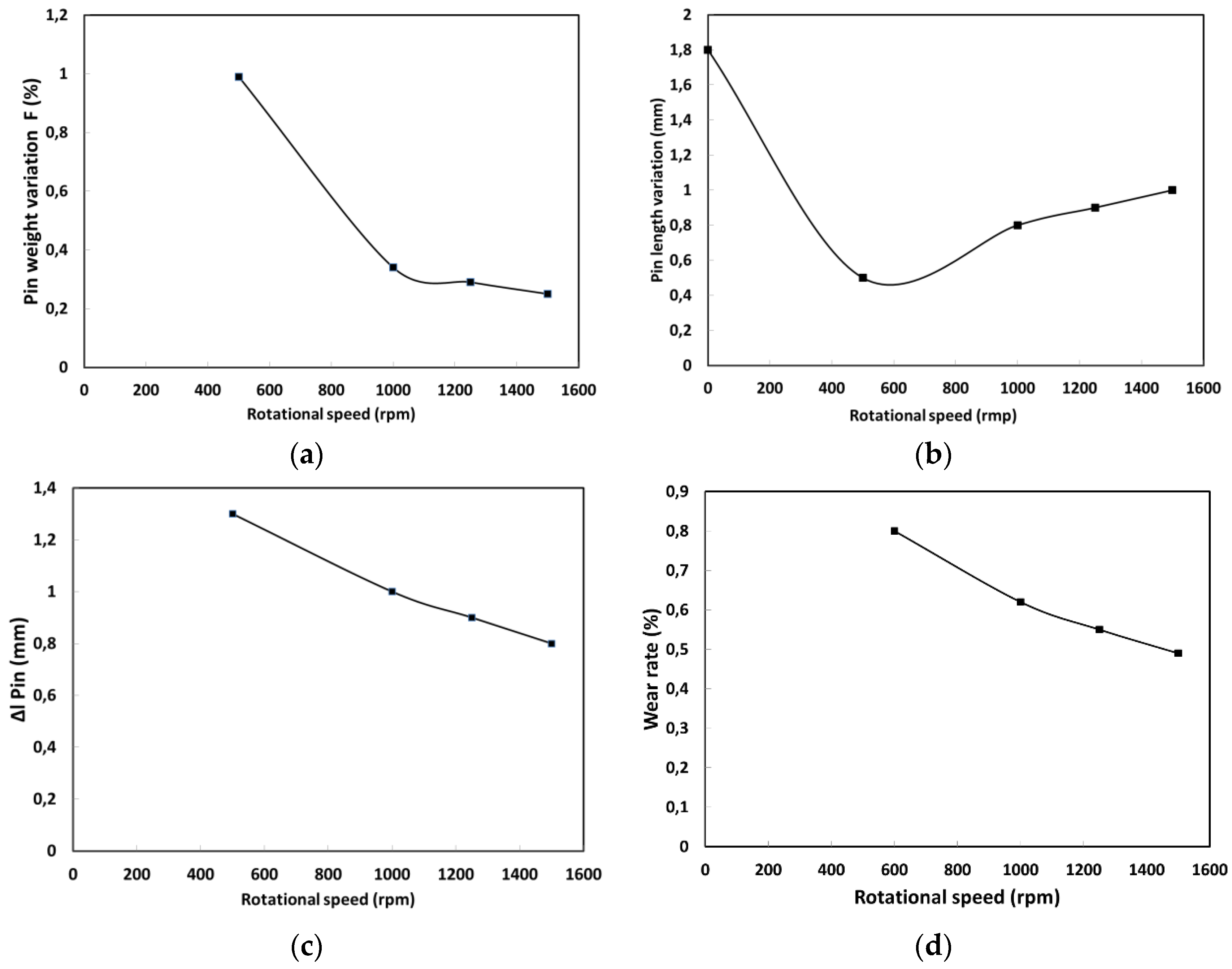
3.2. Quantification of the Tool Wear

Figure 6 illustrates some typical sequences of tool/pin photographs illustrating apparent wear under selected processing conditions. It can be seen that all the tools suffered different degrees of wear. Some oxidations were also observed around the edge of some pins, which is attributed to the presence of tungsten oxide, as also reported by other authors [31]. The most severe wear was observed in the area between the pin center and pin edge, with the pin center being the least worn region. This is an interesting result as it could be used for optimum selection of tool materials. Analysis of the worn tool shape also showed that maximum wear took place under cold weld conditions (Figure 2).
The difference in the tool weight measured with the micro balance before and after processing is illustrated in Table 4. Using the data in Table 4, the percentage of weight variation was calculated and correlated with the tool rotational speed as illustrated in Figure 7a. It can be seen in this figure that the effective tool weight is considerably affected by the rotational speed during the process. A decrease is noticed for all processing conditions; however, it is significantly higher for the lowest tool rotational speed. The pin length variation was also evaluated for the different processing conditions and is represented in Figure 7b,c. It can be seen that the length is also affected and some geometrical changes can be seen in the pin under certain processing conditions and mainly for low rotational speeds. This implies that a consumption of tool material, as indicated by some authors in aluminum alloys [32,33] also occurs during FSW of titanium. However, as mentioned by Casalino et al. [33], tool consumption could be reduced during FSW of aluminum alloys by using coated tools. Finally, tool wear (measured as percentage of weight change) decreases for increased rotational speeds. The above data were used to evaluate tool height variation and wear rate as shown in Figure 7c,d.
Figure 7d shows the wear rate evolution with rotational speed. The initial wear rate (in % wear) is represented by the initial slope of the corresponding curves. It can be seen that the wear rate decreases with increasing the rotational speed in the range of process parameter studied in the present work. These findings are in agreement with those reported by Prado et al. [26] and Alidokht et al. [34] in FSW of aluminum alloys, where a decrease of wear rate was noted with sliding distance and rotational speed. The results suggest that a high wear rate is expected during the initial stages of welding, after which it decreases significantly. This finding is also important and could be used in the optimum material selection for FSW of Ti alloys or similar high strength and low thermal conductivity materials. Furthermore, pins used under high rotational speeds display slightly higher wear resistance compared with those used at lower rotational speeds. This may be related to the higher temperatures and therefore better material workability reached under high rotational speed welding conditions.
SEM analyses of the surface microstructure of the worn tools suggested two possible tool wear mechanisms during FSW. In presumed order of importance, these are oxidative wear of WC (Figure 4 and Figure 6), and the increased brittleness due to the transformation of the WC binder. Lofaj et al. [35] and Casas et al. [36] reported that when WC reacts with oxygen, its volume expands by about 300% via an oxidation process that generates CO gas in the solid. The pressure of this gas is greater than the fracture strength of the WC and therefore leads to crack formation. Furthermore, oxide layers are easily fractured, due to residual tensile stresses associated with different coefficients of thermal expansion between the substrate and the carbide particle. The second mechanism is the increased brittleness due to the transformation of the WC binder [5,20]. The WC binder phase is continuously exposed to severe repetitive conditions due to its contact with the workpiece during FSW. It has been shown that WC exposed to fatigue loading exhibits reduced fracture toughness, erosion resistance and thermal shock resistance [35]. The repetitive cycles of contacts between the tool and material creates fatigue like conditions, resulting in particle fracture in the affected regions. However, it was difficult to determine the contribution of each mechanism as both processes occur almost at the same time.

4. Conclusions

Tool wear during friction stir welding of titanium alloy Ti-6Al-4V was investigated under several processing conditions. The following main conclusions can be drawn from the present study:
  • Tool wear is strongly affected by the tool rotational speed. The highest tool wear was obtained under low rotational speeds.
  • The radial wear of the pin is very different at different locations of the pin, and the maximum wear is produced at about two millimeters from the pin root center under cold weld conditions. The welding speed has a decisive effect on the radial wear rate of the pin, and the maximum wear rate was measured for the lowest rotational speed.
  • Microscopic analysis of the welded joints showed that sound FSW joints of Ti-6Al4V were obtained under the following processing conditions: conical WC pin, WC shoulder, tool rotational speed between 1000 and 1500 rpm.

Author Contributions

M. H. Fesharaki, M. Jahazi and A. Khodabandeh conceived and designed the experiments; M. H. Fesharaki performed the experiments; A. Fall and M. H. Fesharaki carried out metallography analyses and sample preparation; A. Fall and M. Jahazi analyzed the data and wrote the paper.

Conflicts of Interest

The authors declare no conflict of interest.

References

  1. Thomas, W.M.; Nicholas, E.D. Friction stir welding for the transportation industries. Mater. Des. 1997, 18, 269–273. [Google Scholar] [CrossRef]
  2. Lütjering, G.; Williams, J.C. Titanium; Springer: Berlin, Germany, 2003; Volume 2. [Google Scholar]
  3. Zwicker, U. Titanium and Titanium Alloys; Springer: Berlin, Germany, 2007. [Google Scholar]
  4. Saresh, N.; Pillai, M.G.; Mathew, J. Investigations into the effects of electron beam welding on thick Ti-6Al-4V titanium alloy. J. Mater. Process. Technol. 2007, 192, 83–88. [Google Scholar] [CrossRef]
  5. Sanders, D.G.; Ramulu, M.; McCook, E.J.K.; Edwards, P.D.; Reynolds, A.P.; Trapp, T. Characterization of Superplastically Formed Friction Stir Weld in Titanium 6Al-4V: Preliminary Results. J. Mater. Eng. Perform. 2008, 17, 187–192. [Google Scholar] [CrossRef]
  6. Thomas, W.M.; Threadgill, P.L.; Nicholas, E.D. Feasibility of friction stir welding steel. Sci. Technol. Weld. Join. 1999, 4, 365–372. [Google Scholar] [CrossRef]
  7. Mishra, R.S.; Mahoney, M.W. Friction Stir Welding and Processing; ASM International: Geauga County, OH, USA, 2007. [Google Scholar]
  8. Lee, W.-B.; Lee, C.-Y.; Chang, W.-S.; Yeon, Y.-M.; Jung, S.-B. Microstructural investigation of friction stir welded pure titanium. Mater. Lett. 2005, 59, 3315–3318. [Google Scholar] [CrossRef]
  9. Badarinarayan, H.; Yang, Q.; Zhu, S. Effect of tool geometry on static strength of friction stir spot-welded aluminum alloy. Int. J. Mach. Tools Manuf. 2009, 49, 142–148. [Google Scholar] [CrossRef]
  10. Rai, R.; De, A.; Bhadeshia, H.K.D.H.; DebRoy, T. Review: Friction stir welding tools. Sci. Technol. Weld. Join. 2011, 16, 325–342. [Google Scholar] [CrossRef]
  11. Tongne, A.; Jahazi, M.; Feulvarch, E.; Desrayaud, C. Banded structures in friction stir welded Al alloys. J. Mater. Process. Technol. 2015, 221, 269–278. [Google Scholar] [CrossRef]
  12. Farias, A.; Batalha, G.F.; Prados, E.F.; Magnabosco, R.; Delijaicov, S. Tool wear evaluations in friction stir processing of commercial titanium Ti–6Al–4V. Wear 2013, 302, 1327–1333. [Google Scholar] [CrossRef]
  13. Sato, Y.S.; Harayama, N.; Kokawa, H.; Inoue, H.; Tadokoro, Y.; Tsuge, S. Evaluation of microstructure and properties in friction stir welded superaustenitic stainless steel. Sci. Technol. Weld. Join. 2013, 14, 3. [Google Scholar] [CrossRef]
  14. Park, S.H.C.; Sato, Y.S.; Kokawa, H.; Okamoto, K.; Hirano, S.; Inagaki, M. Rapid formation of the sigma phase in 304 stainless steel during friction stir welding. Scr. Mater. 2003, 49, 1175–1180. [Google Scholar] [CrossRef]
  15. Hovanski, Y.; Santella, M.L.; Grant, G.J. Friction stir spot welding of hot-stamped boron steel. Scr. Mater. 2007, 57, 873–876. [Google Scholar] [CrossRef]
  16. Weinberger, T.; Enzinger, N.; Cerjak, H. Microstructural and mechanical characterization of friction stir welded 15–5PH steel. Sci. Technol. Weld. Join. 2013, 14, 210–215. [Google Scholar] [CrossRef]
  17. Park, S.H.C.; Sato, Y.S.; Kokawa, H.; Okamoto, K.; Hirano, S.; Inagaki, M. Boride formation induced by pcBN tool wear in friction-stir-welded stainless steels. Metall. Mater. Trans. A 2009, 40, 625–636. [Google Scholar] [CrossRef]
  18. Yutaka, S.S.; Masahiro, M.; Shinichi, S.; Hiroyuki, K.; Toshihiro, O.; Koyohito, I.; Shinya, I.; Seung, H.C.P.; Itto, S.; Satoshi, H. Performance Enhancement of Co-Based Alloy Tool for Friction Stir Welding of Ferritic Steel. In Friction Stir Welding and Processing VIII; TMS: San Diego, CA, USA, 2015; pp. 39–46. [Google Scholar]
  19. Zhang, Y.; Sato, Y.S.; Kokawa, H.; Park, S.H.C.; Hirano, S. Stir zone microstructure of commercial purity titanium friction stir welded using pcBN tool. Mater. Sci. Eng. A 2008, 488, 25–30. [Google Scholar] [CrossRef]
  20. Edwards, P.; Ramulu, M. Effect of process conditions on superplastic forming behaviour in Ti-6Al-4V friction stir welds. Sci. Technol. Weld. Join. 2009, 14, 669–680. [Google Scholar] [CrossRef]
  21. Fall, A.; Jahazia, M.; Khodabandehb, A.R.; Fesharakib, M.H. Effect of process parameters on microstructure and mechanical properties of friction stir welded Ti-6Al-4V joints. Int. J. Adv. Manuf. Technol. 2016, 87, 1–13. [Google Scholar] [CrossRef]
  22. Nahamin Pardazan Asia. Iran, 2014. Available online: http://en.metsofts.ir (accessed on 6 August 2016).
  23. Dalgaard, E.; Frederik, C.L.; Rabet, M.J.; Priti, W.; John, J.J. Texture Evolution in Linear Friction Welded Ti-6Al-4V. Adv. Mater. Res. 2010, 89–91, 124–129. [Google Scholar] [CrossRef]
  24. Ma, Z.Y.; Pilchak, A.L.; Juhas, M.C.; Williams, J.C. Microstructural refinement and property enhancement of cast light alloys via friction stir processing. Scr. Mater. 2008, 58, 361–366. [Google Scholar] [CrossRef]
  25. Bastier, A.; Maitournam, M.H.; Van, K.D.; Roger, F. Steady state thermomechanical modelling of friction stir welding. Sci. Technol. Weld. Join. 2006, 11, 278–288. [Google Scholar] [CrossRef]
  26. Prado, R.A.; Murr, L.E.; Soto, K.F.; McClure, J.C. Self-optimization in tool wear for friction-stir welding of Al6061 + 20%Al2O3 MMC. Mater. Sci. Eng. A 2003, 349, 156–165. [Google Scholar] [CrossRef]
  27. Tongne, A.; Desrayaud, C.; Jahazi, M.; Feulvarch, E. On material flow in Friction Stir Welded Al alloys. J. Mater. Process. Technol. 2017, 239, 284–296. [Google Scholar] [CrossRef]
  28. Krishnan, K.N. On the formation of onion rings in friction stir welds. Mater. Sci. Eng. A 2002, 327, 246–251. [Google Scholar] [CrossRef]
  29. Vo, P.; Jahazi, M.; Yue, S. Recrystallization During Beta Working of IMI834. Adv. Mater. Res. 2007, 15–17, 965–969. [Google Scholar] [CrossRef]
  30. Yoon, S.; Rintaro, U.; Hidetoshi, F. Effect of initial microstructure on Ti-6Al-4V joint by friction stir welding. Mater. Des. 2015, 88, 1269–1276. [Google Scholar] [CrossRef]
  31. Zackrisson, J.; Jansson, B.; Uphadyaya, G.S.; Andr’en, H.-O. WC-Co based cemented carbides with large Cr3C2 additions. Int. J. Refract. Met. Hard Mater. 1998, 16, 417–422. [Google Scholar] [CrossRef]
  32. Gerlich, A.; Su, P.; North, T.H. Tool penetration during friction stirs spot welding of Al and Mg alloys. J. Mater. Sci. 2005, 40, 6473–6481. [Google Scholar] [CrossRef]
  33. Casalino, G.; Sabina, C.; Michelangelo, M. Influence of shoulder geometry and coating of the tool on the friction stir welding of aluminium alloy plates. Proced. Eng. 2014, 69, 1541–1548. [Google Scholar] [CrossRef]
  34. Alidokht, S.A.; Zadeh, A.A.; Soleymani, S.; Saeid, T.; Assadi, H. Evaluation of microstructure and wear behavior of friction stir processed cast aluminum alloy. Mater. Charact. 2012, 63, 90–97. [Google Scholar] [CrossRef]
  35. Lofaj, F.; Yu, S.K. Kinetics of WC-Co oxidation accompanied by swelling. J. Mater. Sci. 1995, 30, 1811–1817. [Google Scholar] [CrossRef]
  36. Casas, B.; Ramis, X.; Anglada, M.; Salla, J.M.; Llanes, L. Oxidation-induced strength degradation of WC-Co hardmetals. Int. J. Refract. Met. Hard Mater. 2001, 19, 303–309. [Google Scholar] [CrossRef]
Figure 1. Geometry and dimensions of the shoulder and pin tool (a) shoulder and pin tool schematics in (mm) (b).
Metals 06 00275 g001
Figure 2. Macrostructures of the weld joint under cold weld parameters ((a) 600, (b) 700 and (c) 800 rpm) and hot weld condition ((d) 100, (e) 1250 and (f) 1500 rpm) for 100 mm·min−1 tool travel speed.
Metals 06 00275 g002
Figure 3. Effect of tool wear on the microstructure of the cold weld joints: (a) 600 rpm, (b) 800 rpm and (c) 1500 rpm.
Metals 06 00275 g003
Figure 4. Tool wear effect on the microstructure of the hot weld joint (1000 rpm) and EDX analysis.
Metals 06 00275 g004
Figure 5. Optical and SEM images showing the microstructure flow through forwarding sides of the different weld region identified in Figure 5 at 1000 rpm (ac) and 1500 rpm (df).
Metals 06 00275 g005
Figure 6. Photographs of tungsten-based alloy tool after welding at different process conditions.
Metals 06 00275 g006
Figure 7. Wear measurement after 10 cm welding: (a) Weight loss data as function of rational speed; (b) Pin length evolution as function of processing parameter; (c) Pin length variation with rotational speed; (d) Wear rate as function of rotational speed.
Metals 06 00275 g007
Table 1. Mechanical properties of the as received base material Ti-6Al-4V.
PropertyT.S. (MPa)Y.S. (MPa)El. (%)Hardness (VHN)
Value99491017.2344
Table 2. Friction stir welding (FSW) parameter used on the samples.
Weld NumberRotational Speed (rpm)Travel Speed (mm/min)
1500100
2600100
3700100
41000100
51250100
61500100
Table 3. Original size of the welding tool (mm) Shoulder height is considered to be the same as the pin length.
Tool MaterialShoulder DiameterShoulder HeightPin DiameterPin Length
WC15861.8
Table 4. Tungsten based alloy tool weight variation after welding at different process conditions.
rpm/min−1W1 (gr)W2 (gr)W (gr)F (%)
500/10023.76023.550.2100.99
1000/10023.74223.6610.0810.34
1250/10023.96723.8980.0690.29
1500/10023.75223.6930.0590.25

