Article

Influencing Factors for the Microstructure and Mechanical Properties of Micro Porous Titanium Manufactured by Metal Injection Molding

School of Material Science and Engineering, Harbin Institute of Technology, Harbin 150001, China
*
Author to whom correspondence should be addressed.
Metals 2016, 6(4), 83; https://doi.org/10.3390/met6040083
Submission received: 16 March 2016 / Revised: 30 March 2016 / Accepted: 31 March 2016 / Published: 9 April 2016
(This article belongs to the Special Issue Metal Injection Moulding)

Abstract

:
Porous titanium is a new structural and functional material. It is widely used in many fields since it integrates the properties of biomaterials with those of metallic foam. A new technology that combines both the preparation and forming of porous materials has been proposed in this paper. Moreover, a new solder was developed that could be employed in the joining of porous materials. Influencing factors for microstructure and mechanical properties of the parent material and joint interface are identified. Metal injection molding (MIM) technology was used for fabricating porous materials. The feedstock for injection molding of porous titanium powders was prepared from titanium powders and a polymer-based binder system. In addition, the proportion of powder loading and binders was optimized. Through MIM technology, a porous titanium filter cartridge was prepared. For the purpose of investigating the thermal debinding technology of the filter cartridge, effects of the sintering temperature on the porosity, morphology of micropores and mechanical properties were analyzed. It could be found that when the sintering temperature increased, the relative density, bending and compression strength of the components also increased. Moreover, the porosity reached 32.28% when the sintering temperature was 1000 °C. The microstructure morphology indicated that micropores connected with each other. Meanwhile, the strength of the components was relatively high, i.e., the bending and compression strength was 65 and 60 MPa, respectively. By investigating the joining technology of porous filter cartridges, the ideal components of the solder and pressure were determined. Further research revealed that the micropore structure of the joint interface is the same as that of the parent material, and that the bending strength of the joint interface is 40 MPa.

Graphical Abstract

1. Introduction

Titanium has huge potential in field of biomaterials owing to excellent biocompatibility. Titanium-based porous materials are novel materials used for structural and functional applications [1,2,3,4]. Due to their combination of the excellent properties of titanium alloys and metallic foams, titanium-based porous materials are widely used in many fields [5]. However, because of the high processing costs and difficulties informing them, the development and application of titanium-based porous materials are limited. Methods for fabricating porous titanium include applying space holders [6,7,8], but MIM has its unique advantages. It is a novel near-net-shape technology, which has the unique advantage of forming components of complex shapes. This will increase production efficiency and reduce costs. The MIM is a promising technology for fabricating titanium components with micropores because of its low production cost, capability of mass production, and applicability for many materials [9]. This technique has a lot of features which are different from conventional injection mold molding in many aspects such as the higher injection pressure and speed, the higher mold temperature and the vacuum degree in the mold. For the preparation of polymeric micro-products, it is very effective. However, substantial applications, such as porous titanium filtrate cartridges, require specific properties like mechanical properties, which cannot be satisfied by polymeric materials. One way to solve the problem is to produce metal or ceramic micro-products by powder micro-injection mold molding. This technique contains mainly four processing stages, i.e., feedstock preparation, injection mold molding, debinding (followed by pre-sintering) and sintering. In this paper, pure titanium powders were used for the preparation of a porous filter cartridge via MIM technology. Additionally, the morphology of micropores and the mechanical properties of the parts were researched.
On the other hand, conventional welding techniques, such as diffusion welding and fusion welding, is not effective in joining porous materials. For example, the deformation of pores during wielding presumably causes damage to the pore microstructure [10]. There are some studies focusing on improving conventional joining technology. Zhu et al. [11] developed a CaO-Al2O3-SiO2-based glass layer for the joining of porous alumina. Wang et al. [12], using a two-step bonding process, joined a porous membrane with thermal plastic microfluidic devices. However, few reports are found that combine MIM and joining technology for metals. Aimed at investigating the integration of preparation and forming of porous materials and the possibility of joining of them using solder, a new solder for the joining of porous materials of pure titanium was developed. Additionally, the filter cartridge was successfully prepared via MIM and joining technology.

2. Materials and Experimental Procedures

Pure titanium powders with a mean particle size of 22 μm (see Figure 1a,c) were ball-milled for 10 h in ethanol solution using ceramic balls. Feedstock was prepared by mixing pure titanium powders (50 vol. %) and polymer-based binder system (paraffin wax (PW) + polypropylene (PP) + stearic acid (SA)) in a double star mixer. This was followed by several steps: firstly, green mixture was heated up to 180 °C and held for 30 min. Then polymer-based binder system was put into mixer and mixed. After mixture, the feedstock was granulated by single-screw extrusion machine for several times. Plastic temperature and rotation speed of the screw were 180 °C and 600 r/min. Bending samples of green parts were injection-molded by the Babyplast6/10 micro-injection molding machine (Babyplast, Lucca, Italy). The plasticizing temperature and mold temperature were 190 °C and 60 °C, respectively. Injection pressure and cooling time were 100 MPa and 10 s, respectively. Microscopic morphology of the molded green part is shown as Figure 1b. The dimension of bending samples was 3 mm × 4 mm × 40 mm. Samples for compression tests were sectioned from molded bending samples. Molded green parts were debound in a tubular furnace under a temperature of 600 °C and in an Ar protective atmosphere. Then debound samples were sintered at a different temperature (800–1200 °C) for 1 h in an Ar protective atmosphere. The heating rate is 25 °C/min to 800 °C, 15 °C/min to 1000 °C followed by 10 °C/min to 1200 °C. The length of molded parts (Lm) and sintered part (Ls) was measured. The density, microstructure, bending and compression strength of as-sintered samples were measured.
The electronic balance named Sartorius BS124S (Sartorius, Goettingen, Germany) was employed to measure mass changes of different samples. The measurement of porosity was carried out through OLS3000 laser confocal scanning microscopy (LSCM) (Olympus Corporation, Tokyo, Japan). The compositions of test specimens were examined using the X-ray diffraction (XRD, PANalytical B. V., Almelo, The Netherland) in Rigaku D/max-rB using Cu-Kα radiation. Microstructure observation and energy dispersive spectroscopy EDS analysis were carried out using the Quanta 200FEG scanning electron microscope (SEM, FEI company, Hillsboro, OR, USA). Bending and compression tests were performed by the Instron 5500R universal testing machine (Instron Corporation, Norwood, MA, USA). The calculation of strength values was accomplished based on measuring the dimensions of sintered products.

3. Results and Discussion

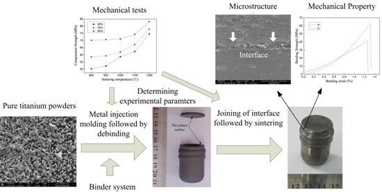
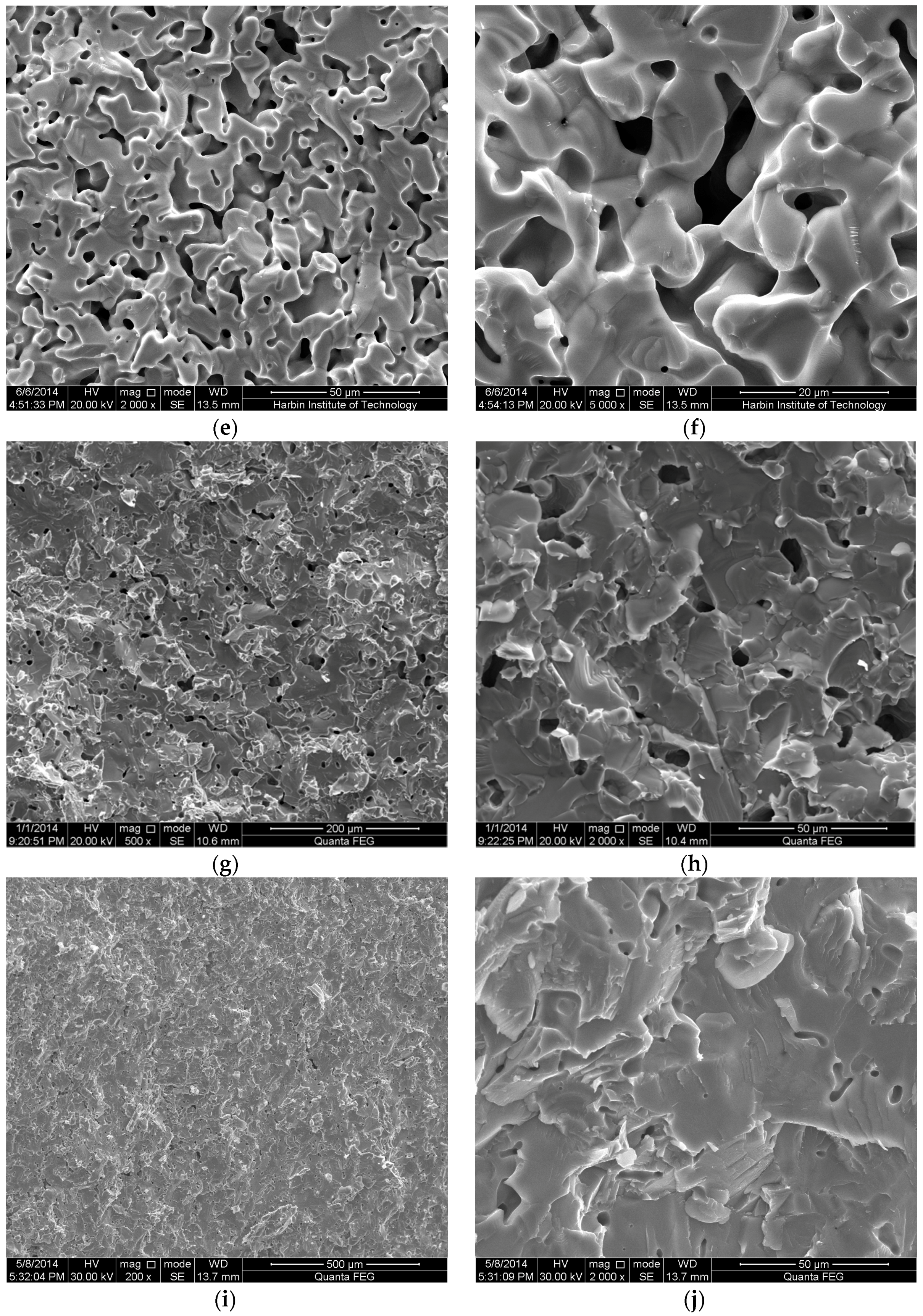
3.1. Component and Morphology of Porous Titanium Prepared by MIM

It is well known that the precision and quality of components are determined by the purity of materials. Binders are inevitably applied in the process of MIM, which will cause pollution in samples and accordingly affect properties negatively if they are not debound completely. In addition, carbides of small molecules will be produced at the debinding stage and the titanium element is highly active. Even a negligible amount of oxygen may result in the pollution of the titanium. Therefore, it is necessary to make sure that the titanium is not polluted. Figure 2a shows the XRD pattern of the debound green part. It can be found that the green part is composed of a simple substance of titanium without any metal oxides that are presumably produced in the debinding process. So it can be safely said that the titanium is not oxidized. Microstructure analysis suggests that binders which encapsulate metallic powders are debound completely, as shown in Figure 2b. Moreover, the clearance between particles is large, suggesting that relative density is low. A low relative density is believed to affect strength greatly. Thus, the strength of the debound green parts is too low to satisfy the requirement for structural application. The following sintering step is to decrease the porosity and accordingly to enhance the strength.
The aim of this paper is to fabricate components with a porous microstructure, so it is necessary to analyze the effect of porosity on the morphology of fracture surfaces. Porosity is not only related to powder loading but also to the process parameters of sintering technology. With the same powder loading, effects of the sintering temperature on porosity and microstructure are investigated. The morphology of the fracture surfaces of products sintered at a different temperature is displayed in Figure 3.
From the morphological observation of the fracture surfaces, it can be found that when the sintering temperature is low (800 °C), the clearance between the particles is large, causing high porosity. With the sintering temperature increasing (900 °C), the microstructure becomes smoother. This is because particles of irregular shapes have a higher surface energy compared with smooth ones. Atoms diffuse to result in a smooth shape for the purpose of decreasing surface energy. Besides, sintering necks can be found but are not obvious, much less a bridge of them. When the sintering temperature increases to 1000 °C, powders have been densified. Larger sintering necks can be seen more clearly and micropores are connected with each other. Thus, liquids or gases can go through them, while solids of a large size cannot pass. Thus, filtration can be achieved. The size of micropores is less than 10 μm, which means that the filtration for liquids or gases is presumably feasible. With the sintering temperature further increasing (1100 °C and 1200 °C), the relative density increases and the sintering neck becomes large enough to interconnect with a few micropores. It deserves attention that sintered products (1200 °C) have such a low porosity that micropores are hardly observed, which is not beneficial for filtration. From the microstructure analysis, it can be concluded that 1000 °C is the ideal sintering temperature. Morphological observation of micropores was carried out via LSCM. Additionally, it is found that the distribution of micropores was even and the diameter of micropores was in the range of 10–20 μm.

3.2. Porosity and Mechanical Property Analysis of Porous Titanium

The measurement of porosity was carried out through LSCM using the plane scanning mode combined with the calculation function of the facility. Density and relative density calculated from the porosity, together with the calculated porosity, are shown in the Table 1. It can be found that the relative density increases with the increase in the sintering temperature, while the porosity decreases. This suggests that micropores become smaller and sintering necks grow in the process of densification. For porous materials, too high or too low a relative density is not ideal. Sintered products with a certain number of micropores can be employed for filtration. At the same time, interconnected sintering necks ensure that strength meets the structural requirement. Therefore, a sintering temperature of 1000 °C is reasonable for fabricating components with excellent comprehensive properties and the components meet both structural and functional requirements. This is consistent with the results of the microstructure analysis.
Bending and compression tests were carried out on sintered products in conditions of different powder loading and sintering temperatures. Both the bending and compression strength are plotted as a function of the sintering temperature (see Figure 4). The general trend indicates that both the bending and compression strength increase with the increase in the sintering temperature. This may be attributed to the fact that larger sintering necks result in higher relative density, which is beneficial for enhancing the strength. However, the increasing rate of the bending and compression strength varies. Besides, even though the sintering temperature is the same, the bending and compression strength varies when the sintering temperature is distinct. This is because the contents of binders are related to porosity, thereby affecting the mechanical properties. The general trend is that relative density increases with the increase in powder loading or sintering temperature. In this regard, a larger sintering temperature and powder loading are ideal. Nevertheless, when the powder loading is 60% the feedstock is difficult, while this phenomenon will not happen if the powder loading is 50% or 55%. Hence, a powder loading of 55% is selected.

3.3. Joining Technology and Interface Analysis of Porous Titanium

When it comes to porous materials, conventional welding technologies, such as fusion welding, generally influence the microstructure of micropores, giving rise to the difference of micropores’ microstructure between the joint interface and parent material. In this paper, a new joining technology has been proposed and a new brazing solder was developed. The experimental steps are illustrated as follows: Firstly, two green parts were fabricated via MIM technology. Secondly, the joining of two green parts was carried out using this new solder. This was followed by debinding and sintering. Finally, the microstructure and strength analysis of the joint interface were carried out in order to evaluate the mechanical properties of the as-joint components. The experimental solder is composed of polyvinyl alcohol and titanium powders. Polyvinyl alcohol and metal powders were mixed in a volume ratio of 1:1 and then heated to 100 °C, combined with stirring until uniform and a paste mixture was obtained. This was followed by a cooling process until room temperature was reached. Before joining, a cartridge of complex shape and a disk were prepared through MIM technology (powder loading is 55%, injection pressure is 100 MPa and plasticizing temperature is 190 °C). The as-prepared products are shown in Figure 5a. Then the joint surfaces of the cartridge and disk were ground using silicon carbide paper of 400 and 800 grit. The mixed solder in the previous procedure was reheated to 80 °C. After that, joint surfaces were smeared with solder, followed by the contact of the two surfaces with pressure, which was determined by the strength of green parts. So compression tests were performed to evaluate the strength of the green parts. It was found that the compression strength of the green parts with a powder loading of 55% is around 10 MPa. The maximum compressive force that green parts were subjected to with different injection pressures was 160 N, 210 N and 230 N, respectively. The compressive force selected for joining was 100 N, with which joining quality was good enough and compression failure could be avoided. The joining was performed at room temperature in air and the as-joint product is shown in Figure 5b. Finally, sintering of the product was carried out in an Ar protective atmosphere (the sintering temperature is 1000 °C). The sintered product is shown in Figure 5c.
The joint surface was sectioned and then analyzed. The typical microstructure is shown in Figure 6. The interface between two parts is obvious (see Figure 6a), and no obvious cavity or gap can be found, indicating that the distribution of the microstructure is even. When amplification of the SEM image is higher (at 2000×, Figure 6b), it can be clearly seen that sintering necks are interconnected. Additionally, the volume fraction of the micropores is appropriate for filtration. Hence, comprehensive properties of the interface are supposed to meet the requirement for both strength and filtration. To ensure, from a quantitative point of view, that the strength meets the requirement, bending tests of the joint surface are designed to be carried out.
Samples for the bending test with a gauge section of 20 mm × 4 mm × 5 mm were cut from the joint surface with an orientation parallel to it. It was also composed of two cuboids with the length of 10 mm. The span length in measuring the bending strength was 16 mm. The bending test results show that the fracture takes place in the joint, suggesting the strength of this region is comparatively low. The bending stress-strain curves of both the joint interface and sintered product are shown in Figure 7, where trace b denotes the curves of products sintered at 1000 °C. The maximum bending strength of the joint interface and sintered products is 40 MPa and 60 MPa, respectively. The strength of the joint interface is obviously lower than that of the sintered products, which can explain why the fracture always takes place in the joint rather than at other regions in the bending tests.

4. Conclusions

(1) A binder system for feedstock suitable for MIM of porous titanium has been developed, where PW is 65 wt. %, PP is 30 wt. % and SA is 5 wt. %. Furthermore, ideal powder loading is determined (55 vol. %).
(2) The porosity, relative density and morphology of fracture surfaces in conditions of different sintering temperatures are analyzed. The ideal sintering temperature is 1000 °C, and the porosity of the as-sintered products is 32.28%. Micropores are interconnected and distributed evenly, and are believed to benefit filtration. The bending and compression strengths are 40 MPa and 55 MPa, meeting the requirement for strength.
(3) A new joining technology using brazing solder for porous titanium is developed. Solder for joining is prepared, and it is composed of 50 vol. % polyvinyl alcohol and 50 vol. % pure titanium powder. The compressive force for joining is 100 N. The SEM image of the joint surface indicates that the microstructure is porous, and the porosity is nearly the same as that of the parent material. The bending strength of the joint surface is 40 MPa, meeting the strength requirement (albeit being lower than that of the parent material (60 MPa)).

Acknowledgments

The financial support from the “China National Natural Science Foundation” (51205081), “Opening Funding of State Key Laboratory of Materials Processing and Die & Mold Technology, Huazhong University of Science and Technology” and “Natural Science Foundation of Heilongjiang Province (QC2013C048)” is greatly acknowledged.

Author Contributions

Zhen Lu conceived the joining of porous material and guided the design of experiments; Zhenhan Huang analyzed data and wrote the paper; Shaosong Jiang contributed helpful discussion and helped settle problems in the experiments; Wei Liu provided analysis tools; Kaifeng Zhang offered instructive suggestion.

Conflicts of Interest

The authors declare no conflict of interest.

References

  1. Lefebvre, L.P.; Banhart, J.; Dunand, D.C. Porous metals and metallic foams: Current status and recent developments. Adv. Eng. Mater. 2008, 10, 775–787. [Google Scholar] [CrossRef] [Green Version]
  2. Schiefer, H.; Bram, M.; Buchkremer, H.P.; Stover, D. Mechanical examinations on dental implants with porous titanium coating. J. Mater. Sci. Mater. Med. 2009, 20, 1763–1770. [Google Scholar] [CrossRef] [PubMed]
  3. Wally, Z.; van Grunsven, W.; Claeyssens, F.; Goodall, R.; Reilly, G. Porous Titanium for Dental Implant Applications. Metals 2015, 5, 1902–1920. [Google Scholar] [CrossRef]
  4. Mohammad, A.; Alahmari, A.; Moiduddin, K.; Mohammed, M.; Alomar, A.; Renganayagalu, R. Porous γ-TiAl Structures Fabricated by Electron Beam Melting Process. Metals 2016, 6, 25:1–25:17. [Google Scholar] [CrossRef]
  5. Ran, H.; Feng, P.; Liu, Z.; Wang, X.; Niu, J.; Zhang, H. Complex-Shaped Porous Cu Bodies Fabricated by Freeze-Casting and Vacuum Sintering. Metals 2015, 5, 1821–1828. [Google Scholar] [CrossRef]
  6. Deing, A.; Luthringer, B.; Laipple, D.; Ebel, T.; Willumeit, R. A porous TiAl6V4 implant material for medical application. Int. J. Biomater. 2014. [Google Scholar] [CrossRef] [PubMed]
  7. Tuncer, N.; Bram, M.; Laptev, A.; Becka, T.; Mosera, A.; Buchkremer, H.P. Study of metal injection molding of highly porous titanium by physical modeling and direct experiments. J. Mater. Process. Technol. 2014, 214, 1352–1360. [Google Scholar] [CrossRef]
  8. Shbeh, M.M.; Goodall, R. Design of water debinding and dissolution stages of metal injection molded porous Ti foam production. Mater. Des. 2015, 87, 295–302. [Google Scholar]
  9. German, R.; Bose, A. Injection Molding of Metals & Ceramics; Metal Powder Industries Federation: Princeton, NJ, USA, 1997; pp. 209–210. [Google Scholar]
  10. Nowacki, J.; Moraniec, K. Welding of metallic AlSi foams and AlSi-SiC composite foams. Arch. Civ. Mech. Eng. 2015, 15, 940–950. [Google Scholar] [CrossRef]
  11. Zhu, W.; Chen, J.; Jiang, C.; Hao, C.; Zhang, J.; Rouxel, T. Joining of Porous Alumina with a CaO-Al2O3-SiO2 Glass-Ceramic. J. Am. Ceram. Soc. 2013, 96, 1738–1744. [Google Scholar] [CrossRef]
  12. Wang, Z.F.; Seah, Y.P.; Wang, Z.P. Seamless joining of porous membrane with thermoplastic microfluidic devices. Microelectron. Eng. 2013, 110, 386–391. [Google Scholar] [CrossRef]
Figure 1. SEM image of (a) pure titanium powders and (b) green parts. (c) Particle size distribution of pure titanium powders.
Metals 06 00083 g001
Figure 2. XRD pattern (a) and SEM image (b) of debound green parts.
Metals 06 00083 g002
Figure 3. Morphology of fracture surfaces of products sintered at a different sintering temperatures ((a) 800 °C; (c) 900 °C; (e) 1000 °C; (g) 1100 °C; (i) 1200 °C) and corresponding images of higher amplification ((b); (d); (f); (h) and (j)).
Metals 06 00083 g003aMetals 06 00083 g003b
Figure 4. Sintering temperature dependence of bending strength (a) and compression strength (b) of sintered products.
Metals 06 00083 g004
Figure 5. Optical photograph of green parts before and after joining: (a) green parts before joining, (b) green parts after joining, (c) sintered products.
Metals 06 00083 g005
Figure 6. Typical SEM images of joint surface: (a) at 200×; (b) at 2000×.
Metals 06 00083 g006
Figure 7. Bending stress-bending strain curves of the joint interface (trace a) and sintered products (trace b).
Metals 06 00083 g007
Table 1. Porosity, density and relative density of sintered products.
Sintering Temperature (°C)800900100011001200
Porosity (%)39.6938.2232.2810.339.20
Density (g/cm3)2.722.793.054.044.14
Relative density (%)60.3161.7867.7289.6791.80

