Article

Formation of Light-Weight Ferroalloys in the Fe2O3-Al2O3-C System at 1550 °C: Influence of Silica Impurities

by
Muhammad Ikram-Ul-Haq
1,
Partha Sarathi Mukherjee
2 and
Rita Khanna
1,*
1
School of Materials Science and Engineering, The University of New South Wales, Sydney, NSW 2052, Australia
2
Institute of Minerals and Materials Technology, Advanced Materials Technology, Bhubaneshwar, Orissa 751013, India
*
Author to whom correspondence should be addressed.
Metals 2017, 7(10), 391; https://doi.org/10.3390/met7100391
Submission received: 16 August 2017 / Revised: 31 August 2017 / Accepted: 19 September 2017 / Published: 25 September 2017

Abstract

:
Light-weight ferro-aluminium alloys are finding increasing application in the transport sector to reduce overall weights, energy costs and CO2 emissions. As the primary production processes of both Fe and Al are among the most energy-intensive industrial processes in the world, there is an urgent need to develop alternate routes for producing Fe-Al alloys. Our group has successfully produced these alloys in the Fe2O3-Al2O3-C system by producing molten iron in situ, followed by the reduction of alumina at 1550 °C and pick-up of Al by Fe. In this article, we report on the influence of silica, a typical impurity present in iron oxide and reductant carbon, on the reduction reactions in this system, and on the formation of ferroalloys. In-depth investigations were carried out on the Fe2O3-SiO2-C and Fe2O3-Al2O3-SiO2-C systems at 1550 °C for times of up to 60 min. Detailed HRSEM/EDS and XRD analysis was carried on the quenched reaction products recovered after various heat treatments. A complete reduction of silica and alumina was observed in the Fe2O3-SiO2-C system, along with the formation of FeSi and SiC. The reduction reactions were relatively slow in the Fe2O3-Al2O3-SiO2-C system. While the formation of SiC, FeSi and mullite (Al6Si2O13) was observed, even small amounts of Fe-Al alloys could not be detected. The presence of silica impurities reduced the formation of Fe-Al to negligible levels by depleting molten iron from the reaction zone, a key ingredient for the low-temperature carbothermic reduction of alumina. This study shows that some impurities can be highly detrimental to the reaction kinetics and the formation of ferroalloys, and great care needs to be exercised during the choice of reaction constituents.

1. Introduction

Ferro-aluminium alloys are advanced materials with high specific strength (strength to density ratio) that have attracted a lot of interest as alternative light-weight materials for the automotive industry. Automobiles are made from a wide variety of materials, including steel, aluminium, copper and plastics. Steel still accounts for more than 60% of an average automobile’s weight [1]. Advanced high-strength steels such as ausforming steels, maraging steels, transformation-induced plasticity (TRIP) and low-alloyed TRIP steels have also been developed [2]. In 2016, nearly 72 million passenger cars and over 22 million commercial vehicles were manufactured worldwide [3]. Reductions in the weight of transport vehicles are expected to lead to improvements in fuel efficiency and reductions in CO2 exhaust emissions. While a reduction in weight has been met, to some extent, by a further thinning of steel frames, the addition of light elements such as Al and Si to Fe-based alloys is increasingly being used to lower the density of steel. Fe-Al-C and Fe-Mn-Al-C based alloys have shown promise as low-density steels with high strength, excellent ductility at room temperature, and high temperature oxidation resistance [4]. The increased use of aluminium in the transport sector has a significant potential to reduce energy consumption and associated greenhouse gas emissions [5]. However, the primary production routes of both key constituents (Fe and Al) are among the most energy-intensive industrial processes in the world. As energy is one of the most important factors in these industries, impacting the cost and environment greatly, there is an urgent need to reduce energy consumption during the production of ferro-aluminium alloys.
Primary production of aluminium by the Hall-Heroult process is ranked among the most energy- and CO2-intensive industrial processes [6]. In the electrolytic cells, alumina is reduced to aluminium metal at carbon anodes via the following reaction: 2Al2O3 + 3C → 4Al + 3CO2 (g). The production of one tonne of aluminium requires ~13–16 MWhr of direct electric current electricity, up to half a tonne of carbon, and two tonnes of alumina. Carbon anode oxidation is responsible for almost 90 percent of onsite CO2 emissions generated during aluminium production (~1.6 metric tonnes of CO2 per metric tonne of primary aluminium). Aluminium smelters consume around 4% of global electricity output, which in turn makes this industry one of the largest sources of greenhouse gas (GHG) emissions [7]. The direct carbothermic reduction of alumina—Al2O3 + 3C = 2Al + 3CO (g)—proposed as an alternative process for primary aluminium production requires temperatures above 2100 °C and suffers from critical design issues [8]. Several attempts are being made to lower the environmental impact of this process, such as reduction of alumina under vacuum [9], use of concentrated solar power [10], radio frequency plasma [11], natural gas and inert gases, etc. [12]. Indirect carbothermic reduction of alumina is also being developed by forming intermediate aluminium compounds, such as chlorides [13], sulphides and nitrides [14], followed by their subsequent decomposition into aluminium.
In the Al2O3 + 3C system, which is in thermodynamic equilibrium at 2200 °C, only 40% of aluminium is retrievable as molten Al-C alloys, and the remaining 60% is found in gaseous phases Al (g) and Al2O (g) [15]. Using molten Cu and Sn, Frank et al. captured some of these gaseous products in metallic solvents, and were successful in achieving the carbothermic reduction of alumina in a temperature range of 1700 °C to 1850 °C with pressures of between 0.08 to 0.20 atm. [16]. The overall driving force for the reduction reaction was determined by the activity of aluminium in the metallic solvent, the temperature and the pressure of CO gas. Our group has successfully lowered the temperature for the carbothermic reduction of alumina to 1550 °C by using molten iron as a solvent and a thermal sink for capturing AlO (g), Al2O (g), and Al (g) gases [17,18,19]. Experimental results for Al2O3-C/Fe at 1550 °C provided unambiguous evidence for chemical reactions occurring in the ternary system, and for the pickup of Al by Fe. This multi-stage reduction process involved the carburization of molten iron, the carbothermic reduction of alumina into sub-oxide gases, the capture and reduction of these gases by solute carbon followed by the capture of aluminium vapour by molten iron to form iron aluminium Fe3Al and Fe3AlC alloys.
As the next step, reduction reactions were carried out in the Fe2O3-Al2O3-C system to produce molten iron in situ, followed by alumina reduction. The kinetics of alumina reduction was found to be significantly enhanced due to the local generation of CO gas and associated turbulence [20]. Direct reduction of two mixed oxides resulted in the formation of Fe3AlC and Fe3Al alloys at 1550 °C in a single step. All studies reported above [17,18,19,20] were carried out on highly pure materials. It is therefore important to establish the role, if any, of key impurities present in constituents prior to extending laboratory-based investigations to commercial scale production of ferroalloys. We used synthetic graphite (99.9% pure) as a reductant in these studies. Due to cost and availability constraints, it is a common practice to use carbonaceous materials such as coals, cokes, natural graphite, etc. as reductants in industrial operations [21]. Silica (up to 60%) is the main mineral impurity present in these materials. In this article, we focus our attention on the role of silica on reduction reactions in the Fe2O3-Al2O3-C system. We report in-depth investigations on Fe2O3-SiO2-C and Fe2O3-Al2O3-SiO2-C systems at 1550 °C as a function of time. Detailed characterization of reaction products was carried out using high-resolution scanning electron microscopy (HRSEM), energy dispersive spectroscopy (EDS) and X-ray diffraction (XRD) to establish the influence of silica on reduction reactions, kinetics and the formation of ferroalloys.

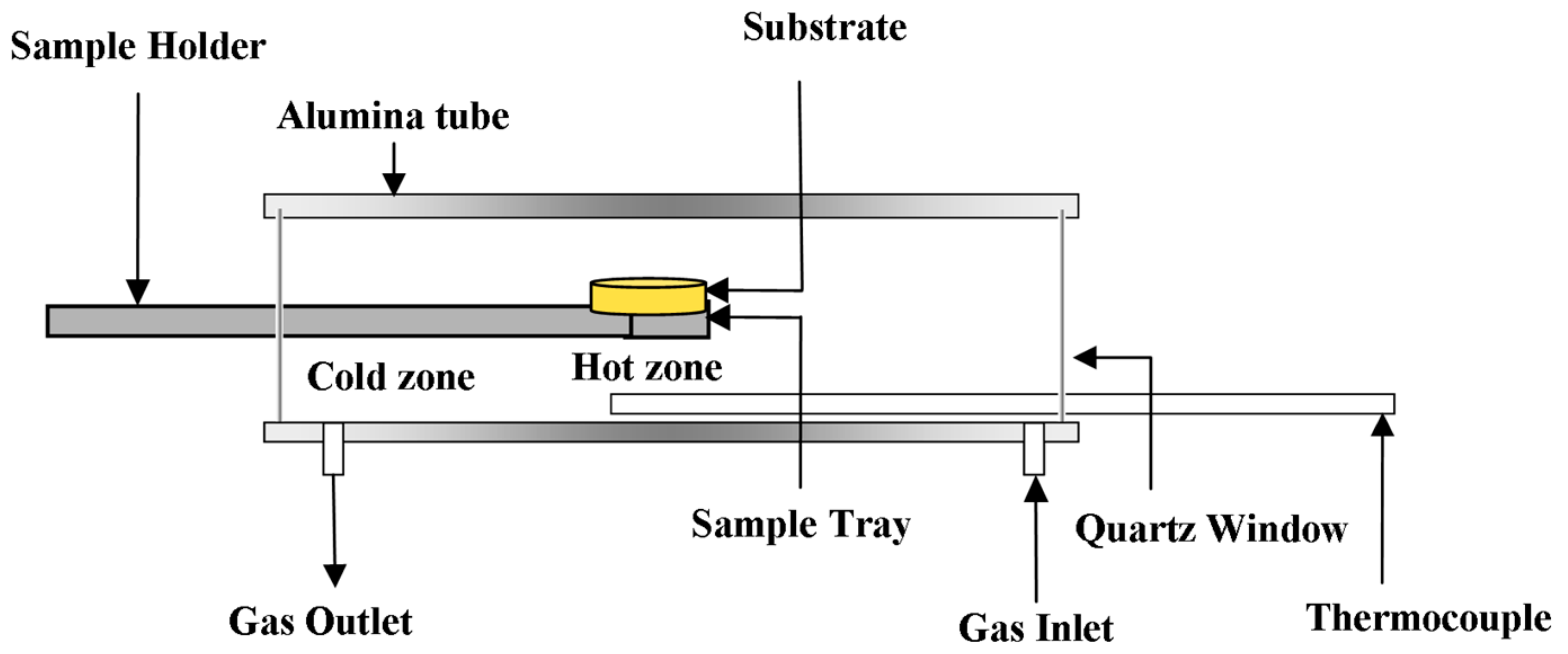
2. Materials and Methods

High purity (≥99.8%) materials were used in this study to prepare two sets of blends. While fused alumina was supplied by Alcoa, other constituents—namely, silica, iron oxide and synthetic graphite powders—were obtained from Sigma Aldrich (Castle Hill, Australia) the average particle sizes of all constituents were ≤50 µm. Two sets of samples were prepared. Powders of SiO2 and Fe2O3 were mixed together in the ratio 70:30 (wt. %) in “Set 1”. In “Set II”, Al2O3, SiO2 and Fe2O3 were mixed together in the ratio 35:35:30 (wt. %). In addition, 35 wt. % graphite and 5 wt. % bentonite (binder) were added to these powder mixtures. These blends were then ball milled for 48 h to ensure a complete and thorough mixing. Cylindrical substrates (25 mm dia., 3 mm thick) were prepared by compacting the mixture in a steel die using a hydraulic press and pressing to a pressure up to 10 MPa. The compacted substrates were baked at 150 °C for 48 h for enhancing their structural integrity. High temperature investigations on Fe2O3-SiO2-C and Fe2O3-Al2O3-SiO2-C substrates were carried out at 1550 °C for times of up to 60 min in a laboratory scale, horizontal tube resistance furnace. The furnace tube was purged with 99.99% pure argon throughout the duration of the experiment, with a flow rate of 1.0 L/min. A schematic representation of the experimental set-up is presented in Figure 1.
Substrate pellets (Sets I and II) were placed on an alumina specimen holder that could be pushed to the centre of the hot zone in the furnace with the help of a graphite rod. The assembly was held in the cold zone of the furnace until the desired temperature (1550 °C) was attained, and then inserted into the hot zone. This eliminated any reaction that could occur at lower temperatures and possibly influence the phenomena under investigation. After heat treatment in the hot zone for fixed periods of time (15, 30 and 60 min), the tray assembly was pulled back into the cold zone of the furnace effectively quenching the sample and halting further reactions.
An in-depth characterization of the reacted assemblies was carried out using a range of analytical techniques. X-ray diffraction data on various reaction products was collected using PANalytical Xpert Multipurpose X-ray Diffraction System (PANalytical, Almelo, The Netherlands) with Cu Kα radiation (45 KV, 40 mA) over an angular range of 10–90° with a step size of 0.01° and a time per step of 30 s. High-resolution scanning electron microscopic investigations were carried out on JEOL 7001F FE-SEM (JEOL USA Inc., Peabody, MA, USA) at sub-micron resolution. The specimens were carbon-coated prior to microscopic investigations. Energy dispersive spectroscopy was carried out on Hitachi S3400 SEMs (magnification: 20× to 20,000×) (Hitachi America, Tarrytown, NY, USA) for microscopic and elemental analysis. Detailed results are presented in the following section.

3. Results and Discussion

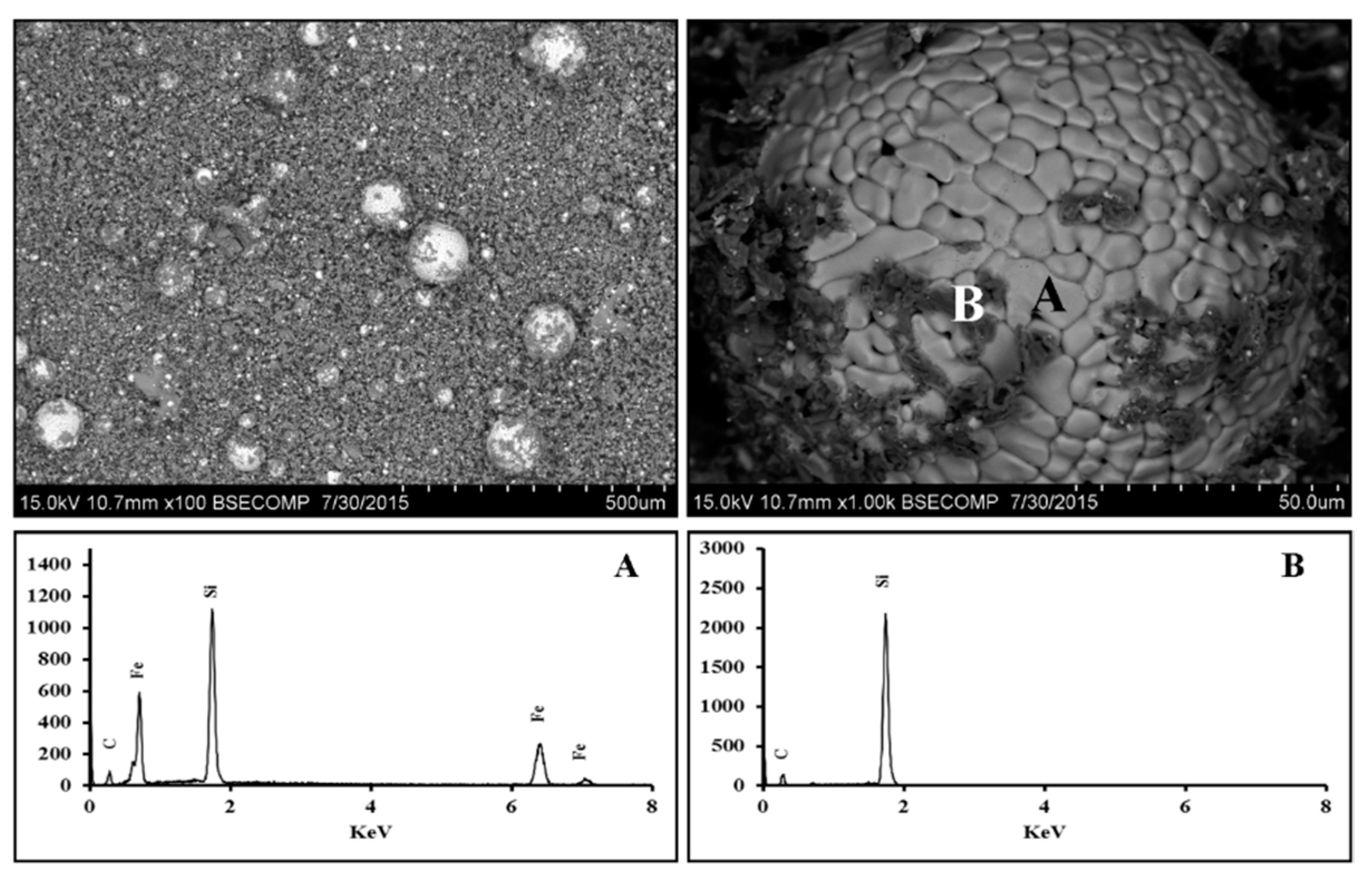
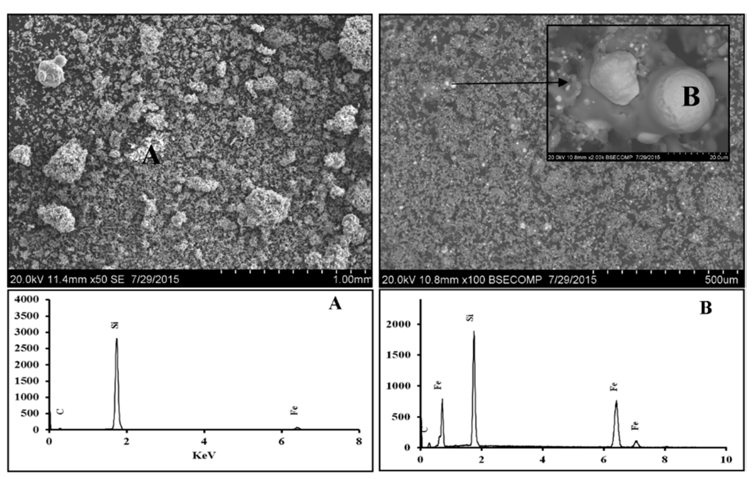
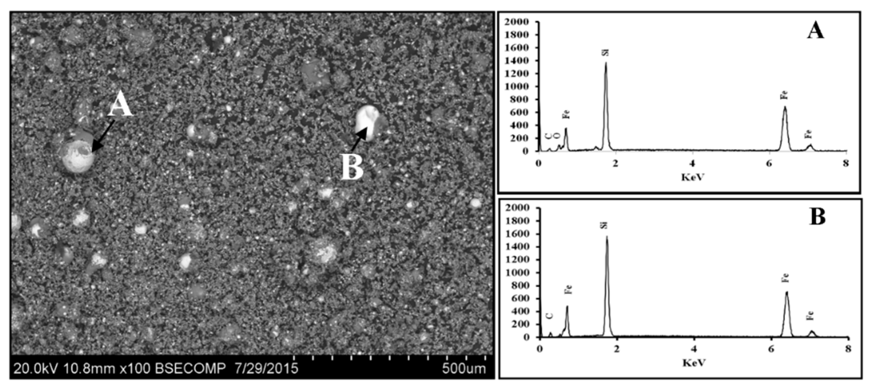
3.1. Fe2O3-SiO2-C System

The weight of the pellets was measured before and after the heat treatments. Mass losses after 15, 30 and 60 min of heat treatment were recorded as 47.93 wt. %, 56.42 wt. % and 64.18 wt. %, respectively. These results indicate rapid reaction kinetics during the initial 15 min and a slowing down at longer times. The mass loss can be attributed to losses in the gas phase as CO, CO2 and SiO gases.

3.1.1. Scanning Electron Microscopy

The HRSEM/EDS results on the reacted assembly after 15 min is shown in Figure 2. These SEM/EDS images indicate a significant level of reduction taking place in the system. The reduction of silica was seen to occur across the sample along with the formation of SiC and small amounts of Fe-Si alloy distributed as tiny metallic droplets throughout the matrix. The spherical shape of these droplets indicates a molten state of the Fe-Si alloys at 1550 °C, a result consistent with Fe-Si binary phase diagram.
The SEM/EDS results after 30 and 60 min of heat treatment are shown in Figure 3 and Figure 4, respectively. Metallic droplets of Fe-Si alloys had grown significantly in size after 30 min. These were, however, present in a wide range of sizes, ranging from very small to quite big. After 60 min of interaction time, the morphology of Fe-Si droplets had changed significantly. Dark patches of SiC were seen sticking to the alloy surface.

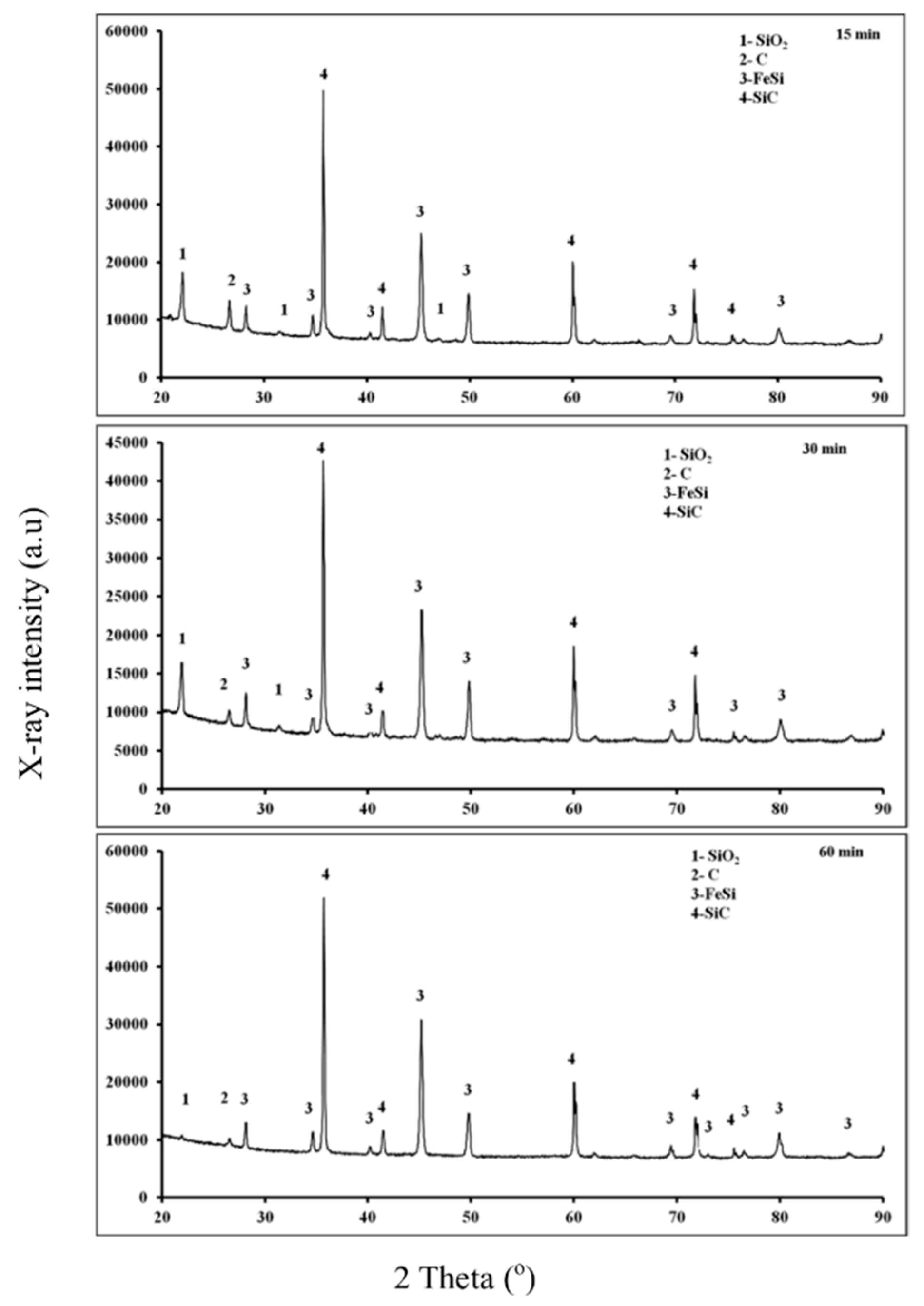
3.1.2. X-ray Diffraction

The detailed X-ray diffraction (XRD) results from reaction products after 15, 30 and 60 min of heat treatment at 1550 °C are shown in Figure 5. After 15 min of heat treatment, iron oxide had reduced completely to iron as no XRD peak could be identified with this phase. This result is consistent with the published literature; the reduction of iron oxide is quite rapid at this temperature, and is expected to reach completion within few minutes [22]. While there was still some unreduced silica and unconsumed carbon, there was clear evidence of the formation of SiC and FeSi phases. Not much change was observed after 30 min. Silica reduction was, however, complete after 60 min, as silica peaks had been much reduced in intensity; the peaks for FeSi and SiC remained quite strong. These XRD results are in good agreement with the HRSEM/EDS results. Both these techniques indicated the reduction of silica and iron oxide, and the formation of SiC and FeSi alloys after various heat treatments at 1550 °C.

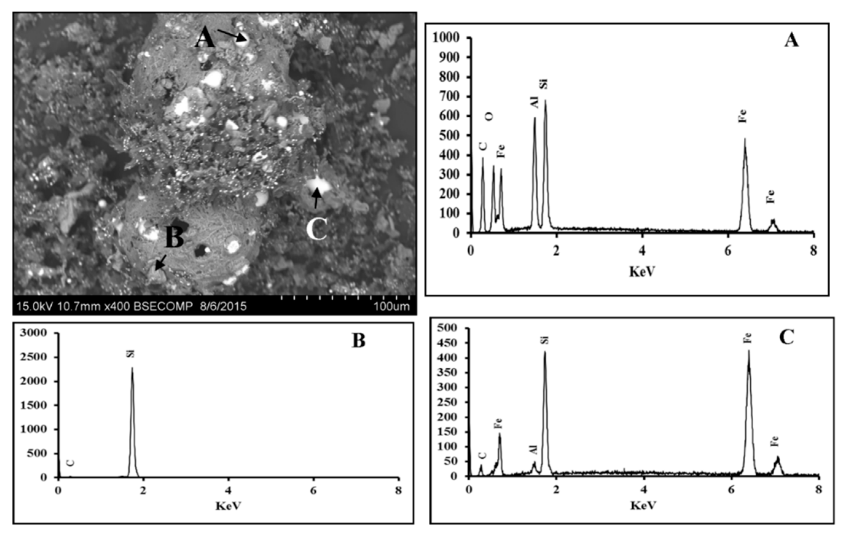
3.2. Fe2O3-Al2O3-SiO2-C System

The weight of the pellets was measured before and after various heat treatments. The mass losses after 15, 30 and 60 min of heat treatment were recorded as 22.19 wt. %, 27.69 wt. % and 31.89 wt. %, respectively. These mass losses are significantly lower than the corresponding results for the Fe2O3-SiO2-C system, thereby indicating much lower levels of reduction reactions.

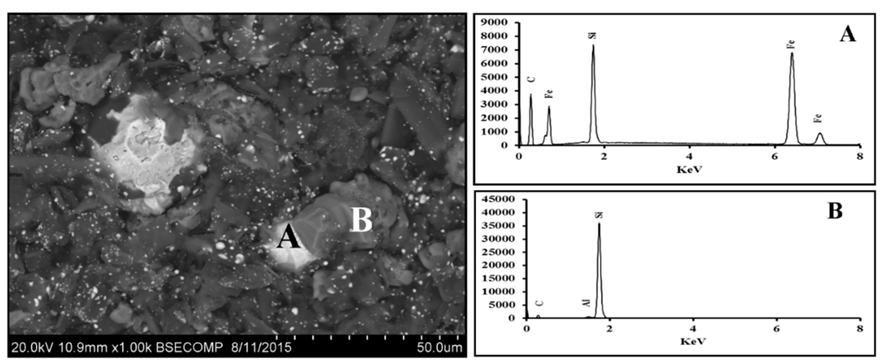
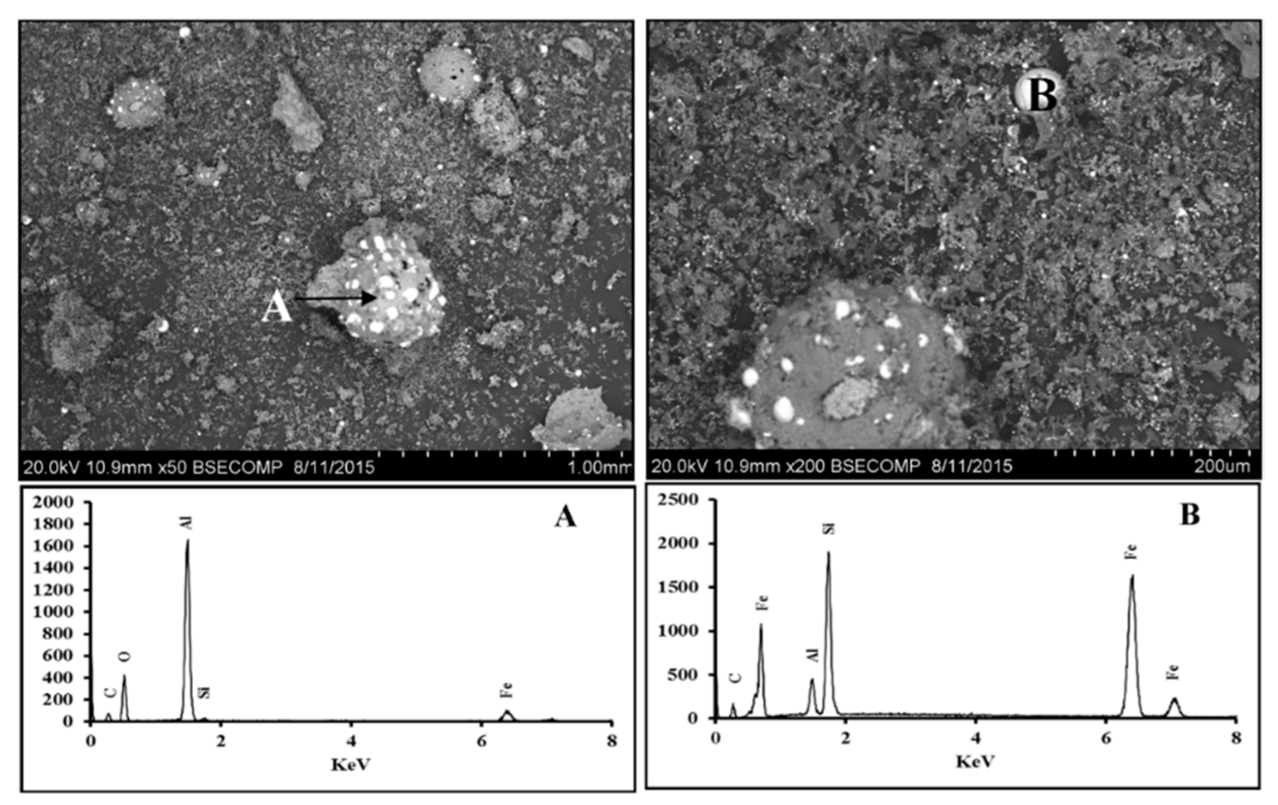
3.2.1. Scanning Electron Microscopy

The HRSEM/EDS results for the reacted assembly after 15 min at 1550 °C are shown in Figure 6. These results indicate the presence of a metallic phase “A”, containing Fe, Si and C, and a phase “B” rich in Si, but containing small amounts of Al and C. Figure 7 and Figure 8 show the corresponding results for reacted assemblies after 30 and 60 min, respectively. Several distinct phases are identified in Figure 7: phase “A”, containing Fe, Si, Al, O and C; phase “B”, containing Si and C; and phase “C”, containing Fe, Si, and small amounts of Al and C (no oxygen). The relative proportions of Fe and Si were very different in phases B and C, indicating significantly different chemical compositions. After 60 min, some of these phases had grown significantly in size (Figure 8). Phase “B”, shown in Figure 8, had a composition quite similar to phase “C”, depicted in Figure 7.

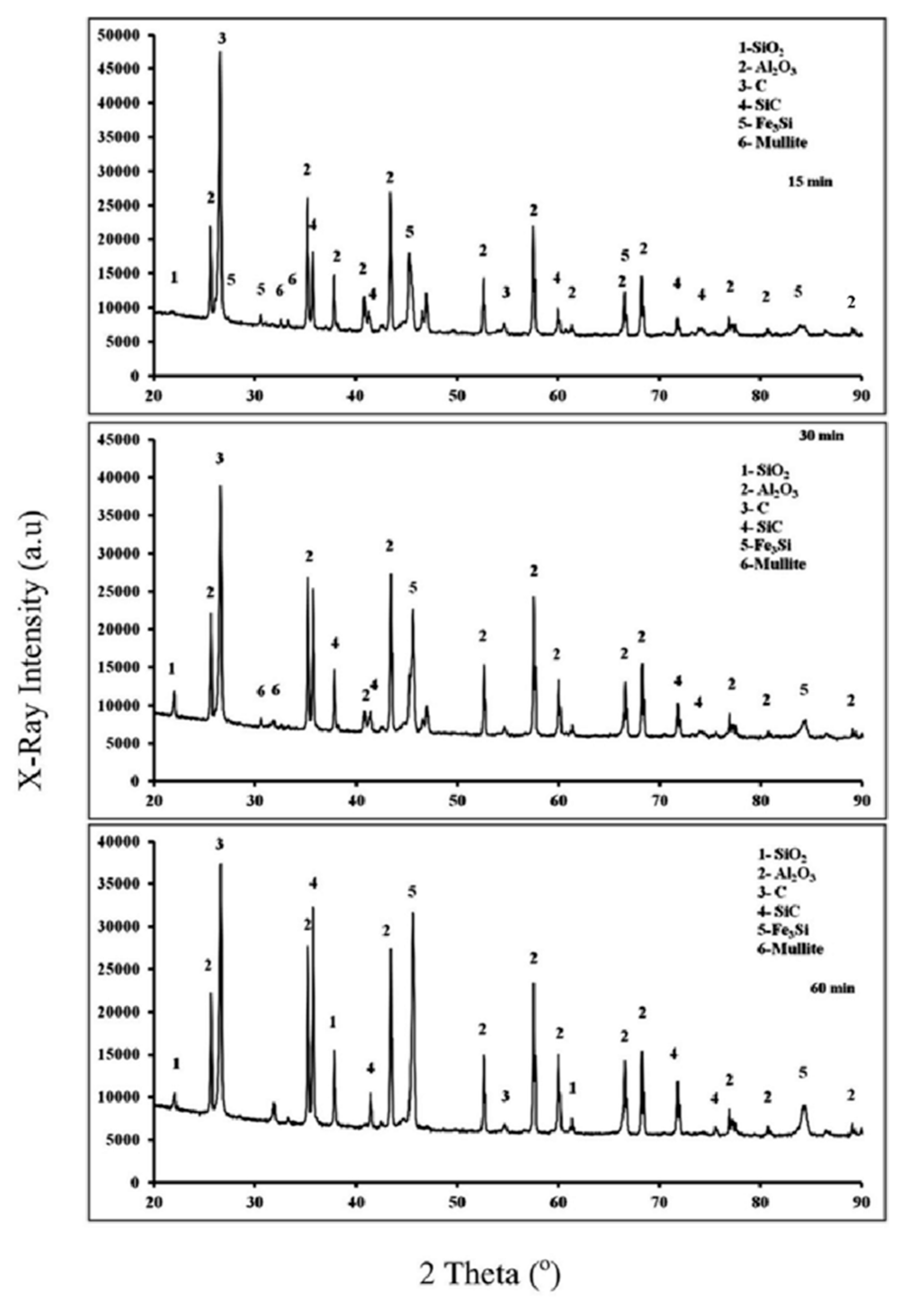
3.2.2. X-ray Diffraction

Detailed X-ray diffraction (XRD) results from reaction products after 15, 30 and 60 min of heat treatment at 1550 °C are shown in Figure 9. This XRD pattern was much more complexthan the one reported in Figure 5 for the Fe2O3-SiO2-C system. After 15 min of heat treatment, in addition to peaks from the unreacted silica, alumina and carbon, there were peaks for SiC, Fe3Si and Mullite (Al6Si2O13). The XRD peaks for these six phases continued to be present after 30 and 60 min. It is important to note that, while there were no peaks for Fe2O3 as expected, the peaks for Fe-Al were absent as well. The Fe-Al peaks, reported previously for the Fe2O3-Al2O3-C system [20], were no longer present in the presence of silica impurities, or were too small to be detected. This result points to a strong detrimental influence of silica impurities on the formation of ferro-aluminium alloys.

3.3. Discussion

There were three reducible oxides in the Fe2O3-Al2O3-SiO2-C system under investigation. The direct reduction of iron oxide with solid carbon takes place as FeO + C = Fe + CO (g), and the indirect reduction of iron oxide occurs through gaseous intermediates as FeO + CO = Fe + CO2 (g) [23]. Being very rapid, the reduction of iron oxide will reach completion within 5 min at 1550 °C, and is not a rate limiting factor in the present investigation. The carbothermic reduction of silica occurs through two basic reactions:
SiO2 (s) + C (s) = SiO (g) + CO (g)
SiO (g) + 2C (s) = SiC (s) + CO (g)
The reaction between SiO2 and C in powdery mixtures (SiO2 + C) has significant rates from about 1400 °C onwards in vacuum or in a stream of argon [23]. Intermediate reaction products from Equations (1) and (2) can react among themselves to produce Si:
SiO (g) + SiC (s) = 2Si + CO (g)
SiO2 + 2SiC = 3Si + 2CO (g)
The reduction of SiO2 to Si is not possible with C alone, but can be achieved through SiC intermediates at temperatures above 1400 °C [24]. Reduced Si, in turn, combines with reduced Fe to form FeSi alloys. Observed experimental results in the Fe2O3-SiO2-C system reported here indicate the formation of FeSi and SiC. Observed results are therefore consistent with these reduction mechanisms.
Alumina is chemically inert at 1550 °C, as it requires temperatures above 2200 °C for carbothermic reduction. Our previous research had established that alumina can undergo carbothermic reduction at 1550 °C in the presence of molten iron, and can form FeAl alloys [17,18,19]. These ferro-aluminium alloys were not detected in the Fe2O3-Al2O3-SiO2-C system under investigation. Key reaction products observed in the system were SiC, Fe3Si and mullite (Al6Si2O13). The reduction kinetics of both silica and iron oxide is very fast at 1550 °C, and reaches completion rapidly. With reduced iron and silicon combining to form FeSi alloys, molten iron was no longer available for alumina reduction. The presence of molten iron was an essential requirement for the low temperature carbothermic reduction of alumina. As molten iron was depleted from the reaction zone by silica impurities, alumina reduction could not take place at these low temperatures. A small fraction of alumina was seen combine with silica to form mullite. The XRD data in Figure 9 did not change significantly after 15 min, thereby indicating most of the reduction reactions had already reached completion by then. The observed HRSEM/EDS results were consistent with XRD findings.

4. Conclusions

The presence of silica impurities had a very detrimental influence on the reduction reactions in the Fe2O3-Al2O3-C system and on the formation of ferro-aluminium alloys. We had successfully produced a range of Fe-Al alloys from direct carbothermic reduction at 1550 °C [17,18,19,20]. However, the low temperature carbothermic reduction of alumina had reduced to negligible levels in the presence of silica impurities, and ferro-aluminium alloys were no longer formed. This change was caused by the removal of molten iron from the reaction zone by silicon to form FeSi alloys. As molten iron was used as a thermodynamic sink and a solvent during reduction reactions, its presence was an essential requirement for the occurrence of carbothermic reduction of alumina at 1550 °C. This study has shown that great care needs to be taken during the formation of ferroalloys from low-temperature reduction reactions of mixed oxides. Impurities should be avoided to the extent possible, even during large-scale alloy making.

Acknowledgments

The financial support for this project was provided by the Australian Research Council under the Discovery Project Scheme DP130102639. The analytical facilities used in this study were provided by the Mark Wainwright Analytical Centre, UNSW, Sydney, Australia.

Author Contributions

All authors contributed equally to the article. Rita Khanna conceived the project, Muhammad Ikram-Ul-Haq carried most of the experimental investigations. All three authors carried out data analysis and contributed to writing, analysis, discussion and conclusions.

Conflicts of Interest

The authors declare no conflict of interest.

References

  1. Steels for the Cars of Tomorrow. Available online: https://www.mpg.de/938220/Steel_for_the_Cars_of_Tomorrow (accessed on 26 July 2017).
  2. Chatterjee, S. Transformations in TRIP-Assisted Steels: Microstructure and Properties. Ph.D. Thesis, University of Cambridge, Cambridge, UK, 2006. [Google Scholar]
  3. World Motor Vehicle Production by Country and Type. Available online: http://www.oica.net/wp-content/uploads//Total-2016.pdf (accessed on 28 July 2017).
  4. Sutou, Y.; Kamiya, N.; Umino, R.; Ohnuma, R.; Ishida, I. High strength Fe-20Mn-Al-C alloys with low density. ISIJ Int. 2010, 50, 893–899. [Google Scholar] [CrossRef]
  5. Energy Trends in Selected Manufacturing Sectors: Opportunities and Challenges for Environmentally Preferable Energy Outcomes. Available online: https://archive.epa.gov/sectors/web/pdf/ch3-1.pdf (accessed on 26 July 2017).
  6. Grjotheim, K.; Krohan, C.; Malinovsky, M.; Malinovsky, K.; Thonstad, J. Aluminium Electrolysis: Fundamentals of the Hall-Heroult Process, 2nd ed.; Aluminium-Verlag: Dusseldorf, Germany, 1982. [Google Scholar]
  7. Mitigating Emissions from Aluminum. Available online: http://climate.columbia.edu/files/2012/04/GNCS-Aluminum-Factsheet.pdf (accessed on 28 July 2017).
  8. Ikram-Ul-Haq, M.; Khanna, R.; Mukherjee, P.S.; Sahajwalla, V. Recent developments in lower temperature carbothermic reduction of alumina as alternative routes for aluminium production. Mater. Sci. 2017, 11, 1–18. [Google Scholar]
  9. Halmann, M.; Epstein, M.; Steinfeld, A. Vacuum carbothermic reduction of alumina. Miner. Process. Extr. Metall. Rev. 2011, 32, 247–254. [Google Scholar] [CrossRef]
  10. Vishnevetsky, I.; Epstein, M.; Rubin, R. Solar carboreduction of alumina under vacuum. Energy Procedia 2014, 49, 2059–2069. [Google Scholar] [CrossRef]
  11. Wai, C.; Hutchison, S. A thermodynamic study of the carbothermic reduction of alumina in plasma. Metall. Mater. Trans. B 1990, 21, 406–408. [Google Scholar] [CrossRef]
  12. Li, J.; Zhang, G.; Liu, D.; Ostrovski, O. Low-temperature Synthesis of Aluminium Carbide. ISIJ Int. 2011, 51, 870–877. [Google Scholar] [CrossRef]
  13. Ferguson, R.P.; Cranford, N.J. Producing Aluminium Halides by the Reaction of Alumina, Carbon and Free Halogen. U.S. Patent 2,446,221 A, 3 August 1948. [Google Scholar]
  14. Dewan, M.; Rhamdhani, M.; Brooks, G.; Monaghan, B.; Prentice, L. Alternative Al production methods: Part 2—Thermodynamic analyses of indirect carbothermal routes 2013. Miner. Process. Extr. Metall. 2013, 122, 113–121. [Google Scholar] [CrossRef]
  15. Balomanos, E.; Panias, D.; Paspalaris, I.; Friedrich, B.; Jaroni, B.; Steinfeld, A.; Gugliemini, E.; Halman, M.; Epstein, M.; Vishnevsky, I. Carbothermic Reduction of Alumina: A Review of Developed Processes and Novel Concepts. In Proceedings of the EMC 2011, European Metallurgical Conference, Berlin, Germany, 26–29 June 2011; pp. 729–744. [Google Scholar]
  16. Frank, R.A.; Finn, C.W.; Elliot, J.F. Physical chemistry of the carbothermic reduction of alumina in the presence of a metallic solvent: Part II. Measurements of kinetics of reaction. Metall. Mater. Trans. B 1989, 20, 161–173. [Google Scholar] [CrossRef]
  17. Khanna, R.; IKram-ul-Haq, M.; Wang, Y.; Seetharaman, S.; Sahajwalla, V. Chemical interactions of alumina–carbon refractories with molten steel at 1823 K: Implications for refractory degradation and steel quality. Metall. Mater. Trans. B 2011, 42, 677–684. [Google Scholar] [CrossRef]
  18. Ikram-ul-Haq, M.; Khanna, R.; Kongkarat, S.; Sahajwalla, V. Chemical interactions in Al2O3-C/Fe system at 1823 K: Implications for refractory recycling. ISIJ Int. 2012, 52, 1801–1808. [Google Scholar] [CrossRef]
  19. Khanna, R.; Ikram-ul-Haq, M.; Seetharaman, S.; Sahajwalla, V. Carbothermic reduction of alumina at 1 823 K: On the role of molten iron and reaction mechanisms. ISIJ Int. 2016, 56, 1300–1302. [Google Scholar] [CrossRef]
  20. Khanna, R.; Ikram-ul-Haq, M.; Sadi, S.F.; Sahajwalla, V.; Mukherjee, P.S.; Seetharaman, S. Reduction reactions in Al2O3-C-Fe and Al2O3-C-Fe2O3 systems at 1823 K. ISIJ Int. 2014, 54, 1485–1490. [Google Scholar] [CrossRef]
  21. Khanna, R.; McCarthy, F.; Sun, H.; Sahajwalla, V.; Simento, N. Dissolution of carbon from coal-chars into liquid iron at 1550 °C. Metall. Mater. Trans. B 2014, 36, 719–729. [Google Scholar] [CrossRef]
  22. Rahman, M.; Khanna, R.; Sahajwalla, V.; O’Kane, P. The influence of ash impurities on interfacial reactions between carbonaceous materials and EAF slag at 1550 °C. ISIJ Int. 2009, 49, 329–336. [Google Scholar] [CrossRef]
  23. Sahajwalla, V.; Mehta, A.S.; Khanna, R. Influence of slag composition and ash impurities on the phenomena occurring in the carbon/slag interfacial region. Metall. Mater. Trans. B 2004, 35, 75–84. [Google Scholar] [CrossRef]
  24. Filsinger, D.H.; Bourrie, D.B. Silica to silicon: Key carbothermic reactions and kinetics. J. Am. Ceram. Soc. 1990, 73, 1726–1732. [Google Scholar] [CrossRef]
Figure 1. A schematic representation of the experimental arrangement.
Metals 07 00391 g001
Figure 2. The presence of two distinct phases, “A” and “B”, in the SEM/EDS micrographs. Phase “A”, in the form of fine powder, mainly contains Si and C; and phase “B”, in the form of shiny metal droplets, has Si and Fe as its main constituents.
Metals 07 00391 g002
Figure 3. The presence of a large number of Fe-Si alloy droplets in a range of sizes across the specimen. The dark powder in the background is unreduced silica and or silicon carbide. Phases “A” and “B” represent ferro-silicon alloys produced in the system.
Metals 07 00391 g003
Figure 4. A further increase in the size of Fe-Si droplets is observed after 60 min. A distinct morphology (“A”) was seen developing on the droplet surface, along with some small dark deposits of SiC carbide adhering to the surface.
Metals 07 00391 g004
Figure 5. X-ray diffraction results from reacted assemblies after a range of reaction times. Phases present were identified as: (1) unreacted SiO2, (2) unused graphite, (3) FeSi alloy, and (4) SiC.
Metals 07 00391 g005
Figure 6. The HRSEM/EDS images for the reacted assembly after heat treatment for 15 min at 1550 °C, indicating a complex mixture of phases.
Metals 07 00391 g006
Figure 7. The HRSEM/EDS images for the reacted assembly after heat treatment for 30 min at 1550 °C. The EDS results for the three phases show significant differences in compositions.
Metals 07 00391 g007
Figure 8. The HRSEM/EDS images for the reacted assembly after heat treatment for 60 min at 1550 °C. Phases A and B were also detected after 30 min of heat treatment.
Metals 07 00391 g008
Figure 9. X-ray diffraction results from reacted assemblies after a range of reaction times. Phases present were identified as: (1) unreacted SiO2, (2) alumina, (3) carbon, (4) SiC, (5) Fe3Si, and (6) Mullite.
Metals 07 00391 g009

