On the Use of Maximum Force Criteria to Predict Localised Necking in Metal Sheets under Stretch-Bending


Department of Mechanical Engineering and Manufacturing, University of Seville, Camino de los Descubrimientos s/n, 41092 Seville, Spain
*
Author to whom correspondence should be addressed.
Metals 2017, 7(11), 469; https://doi.org/10.3390/met7110469
Submission received: 10 October 2017
/
Revised: 27 October 2017
/
Accepted: 30 October 2017
/
Published: 2 November 2017
(This article belongs to the Special Issue Advances in Plastic Forming of Metals)
Abstract
:The maximum force criteria and their derivatives, the Swift and Hill criteria, have been extensively used in the past to study sheet formability. Many extensions or modifications of these criteria have been proposed to improve necking predictions under only stretching conditions. This work analyses the maximum force principle under stretch-bending conditions and develops two different approaches to predict necking. The first is a generalisation of classical maximum force criteria to stretch-bending processes. The second approach is an extension of a previous work of the authors based on critical distance concepts, suggesting that necking of the sheet is controlled by the damage of a critical material volume located at the inner side of the sheet. An analytical deformation model is proposed to characterise the stretch-bending process under plane-strain conditions. Different parameters are considered, such as the thickness reduction, the gradient of variables through the sheet thickness, the thickness stress and the anisotropy of the material. The proposed necking models have been successfully applied to predict the failure in different materials, such as steel, brass and aluminium.
1. Introduction
The maximum force principle has been extensively used in the past to study sheet formability. Considère’s maximum force criterion (MFC) states that diffuse necking is initiated in a tensile test of a bar when the maximum force is reached. The classical models of Swift [1] and Hill [2] are extensions of the MFC for the determination of necking in metal sheets subjected to different stretching conditions in the sheet plane. The former is applicable to the prediction of diffuse necking in the entire domain of the forming limit diagram (FLD). The latter is coupled with the initiation of strain localisation along a narrow band and is limited to predict localised necking in the left side of the FLD. Later, Hora et al. [3] extended the MFC to predict strain localisation for both sides of the FLD by including the contribution of the minor principal strain.
The simplicity of necking criteria based on the maximum force principle make them very attractive. However, their predictions do not always agree with experimental results. Many extensions and alternatives to the MFC have been proposed to date, to deal with predicting localised necking. For instance, Bressan and Williams [4] suggested that failure occurs when the shear stress reaches a maximum. Hora et al. [5] proposed a phenomenological criterion, which states that once the maximum force is reached, the loading path gradually evolves towards plane strain and then localisation occurs. Brunet and Morestin [6] included the effects of damage to refine the material model for the prediction of the necking curve in the FLD. Recently, Aretz [7] assumed that localised necking does not necessarily occur when the axial force reaches a maximum, but rather when it reaches a critical value. This method aimed to scale the Hill’s model so that the major strain predicted by the M–K model [8] or its experimental counterpart at plane-strain conditions (usually referred to as ) was matched.
The above criteria, which are collectively referred to as maximum force criteria (MFCs), were developed to predict necking in nearly stretching operations, neglecting implicitly the strain and stress gradients through the sheet thickness. However, in sheet metal forming processes such as stretch-bending or stamping with punches of mild or severe radii, it is well known that the occurrence of bending has a “beneficial effect” on the initiation of necking. In practice, the average strain through the sheet thickness (or the strain at the middle of the sheet surface) has been used to characterise failure criteria. However, the predictions of this approach, sometimes called the mid-plane rule (MPR), are in general very conservative.
Research carried out to analyse the sheet failure in simultaneous stretching and bending conditions has followed a different approach from the maximum force principle. Tharrett and Stoughton [9] studied the bending effect on sheet failure and proposed a necking criterion referred to as the concave-side rule (CSR). This criterion establishes that the failure is initiated when the strain at the inner surface (concave side) of the sheet reaches a critical value at the bending zone, which matches the limit strain of in-plane stretching. This criterion notably improved the predictions of sheet failure in some materials compared to the MPR. In a later study, authors recognised that stresses are less sensitive to strain path changes, and consequently they reformulated the CSR in terms of stresses [10].
In a previous work, the present authors proposed a natural improvement of the CSR [11]. The model assumes that necking should be controlled by the development of damage in a material volume located at the inner side of the sheet. The study concludes that the critical size of this volume (represented by a certain critical distance from the sheet surface) should be related to the material microstructure.
This work analyses the maximum force principle under stretch-bending conditions, proposing an analytical deformation model to characterise the stretch-bending process under plane-strain conditions. Different generalisations of the MFC for stretch-bending conditions are presented and discussed. As a result, the study suggests that the effect of the existence of strain and stress gradients on sheet thickness may be assessed by applying the MFCs locally at a given material’s critical distance from the inner surface. The proposed necking models are successfully applied to describe the failure by necking in sheets under stretch-bending conditions in different materials, such as 1008 AK steel, 70/30 brass, 6010 aluminium alloy and 7075-O aluminium alloy.
2. Maximum Force Criteria
Considère’s analysis of the uniaxial tension of a metal bar states that diffuse necking appears when the maximum force is applied, that is, , with . Swift extended this model to biaxial loading of a metal sheet of thickness , represented schematically in Figure 1, assuming a simultaneous maximum of both components of the force , , with and [1].
Hill also formulated a criterion to predict localised necking in metal sheets [2]. A simplified formulation of this model states that the localisation is initiated when the load per unit of width reaches its maximum: , with . The application of the Hill criterion is restricted to the left-hand side of the FLD, that is, uniaxial-stretching.
To predict localised necking in both sides of the FLD, Hora extended Considère’s model to biaxial loading of a metal sheet and considered that the major principal stress () is a function of both major () and minor () principal strains in the plane of the sheet [3].
The above models of plastic instability lead to the formulation of the MFCs in a single and unified expression:
where the left-hand side is a material property, sometimes referred to as the non-dimensional strain-hardening characteristic, whereas Z is the critical value for the subtangent of the stress–strain curve [12]. The former is evaluated using a stress–strain constitutive equation and the latter, by a yield function under plane-stress conditions, which can be characterised by the following parameters:
The expressions for the above parameters are given in Appendix A for both Hosford and Mises yield criteria.
It is not intended in this article to review the formulation of these well-known models. There are several works in the literature that analyse these and provide specific expressions of Equation (1) (e.g., [13,14,15]). Most of these assume a Hollomon law () to evaluate the aforementioned material characteristic and a Mises yield function to evaluate . For instance, the Hill necking criterion [2] under proportional load transforms Equation (1) to
which leads to algebraic expressions to evaluate the principal strains:
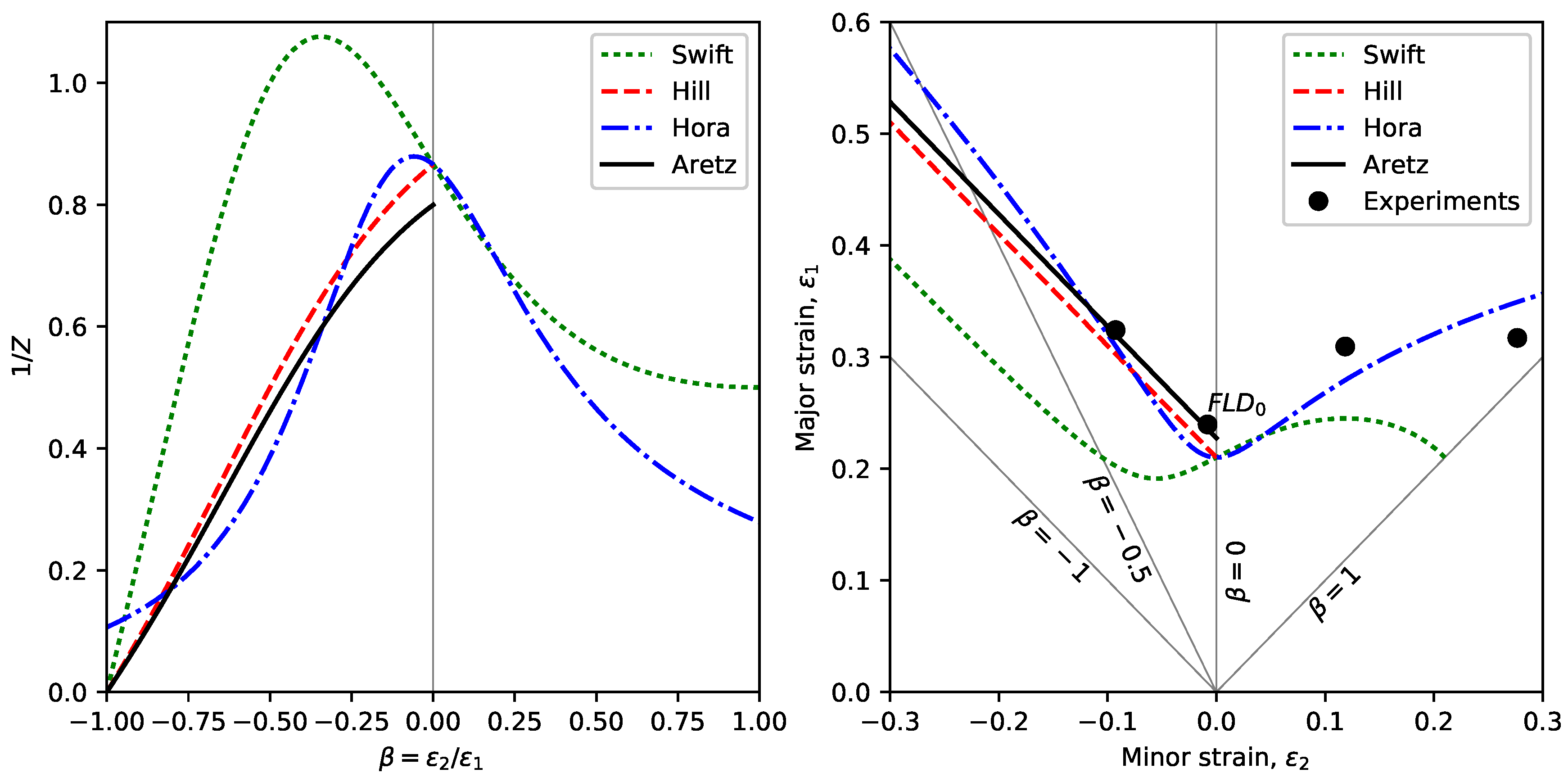
Figure 2 presents an illustrative example of the application of the Swift [1], Hill [2] and Hora [3] criteria to predict necking in AA7075-O metals sheets. Both sides of Equation (1) have been evaluated by assuming a Hollomon law and a Mises yield criterion, respectively. Critical values of are represented in Figure 2a as functions of the strain path under proportional loading conditions. Figure 2b presents necking predictions in the FLD along with the experimental data of localised necking reported by Martínez-Donaire et al. [16] for AA7075-O sheets of 1.6 mm thickness. The coefficient of the Hollomon law was found to be . As can be observed, both Hill and Hora criteria for localised necking reproduce the experimental data in their respective ranges of application reasonably well.
Figure 2 also presents the failure predictions of a modified Hill criterion based on Aretz’s approach [7]. Aretz assumed that necking is initiated when the axial force reaches a critical value, rather than its maximum value. The fundamental idea of this approach lies in the calibration of the critical load, which is obtained by scaling the prediction of Hill’s model (4) to fit the major strain at necking under plane-strain conditions (). Accordingly, Equation (1) is turned into
which leads to
3. Stretch-Bending Deformation Model
Under stretch-bending conditions, strain and stress gradients through the sheet thickness are induced in the metal sheet. In this situation, the MFCs must to be reformulated to take into account these gradients.
The following deformation model is an extension of a stretch-bending model developed in a previous work [11]. This model assumed that the sheet adapts to the punch geometry in an earlier stage mainly by bending followed by a dominant stretching process until the sheet failure is reached. By simplicity, the evolution of the sheet curvature at the earlier stage is neglected, assuming this to be fixed and equal to the punch curvature. The model assumes that the deformation process is controlled by the reduction of sheet thickness.
In order to be able to integrate analytically the radial equilibrium equation, which relates principal stresses through the sheet thickness, only a plane-strain condition () is assumed hereafter. The effect on sheet failure of the through-thickness stress is also taken into account.
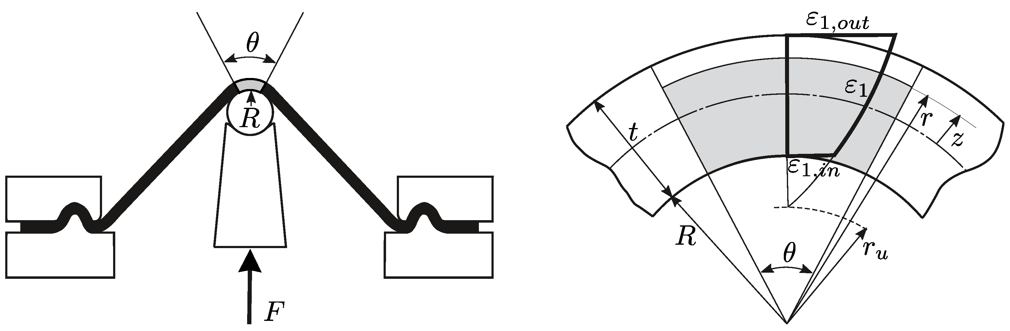
Figure 3 shows the model variables in a sheet element located at the dome of the punch that is subjected to stretch-bending. The undeformed sheet dimensions are and the initial thickness is . In the deformed configuration, t is the current thickness, and the punch radius R matches the radius of curvature of the inner surface.
In this configuration, is the bent angle, r is the radius of curvature of a given layer, is the position of the layer measured from the middle surface, and is the radius of curvature of the unstretched surface. We note that all layers on the thickness are stretched () when stretching dominates over bending. The current length of a generic layer, which initially had an undeformed length of , is .
The principal true strain distributions through the sheet thickness can be written as
where can be obtained from the material incompressibility condition of the sheet element:
leading to
Substituting Equation (9) into Equation (7), the major strain can be expressed as a function of the variables t and r, and the parameters and R, as follows:
We note that the major strain at the outer and inner sides of the sheet ( and , as shown in Figure 3) are given by Equation (10) by substituting and , respectively.
The distribution of principal stresses in the sheet thickness are obtained from the radial equilibrium equation [17]:
Given that from Equation (7), it is convenient to change the variable r for in Equation (11) and write the radial equilibrium equation as
The anisotropic non-quadratic yield criterion proposed by Hosford is assumed. This provides simplified expressions for the equivalent stress and strain under plane-strain conditions (see Appendix B):
where C is a function of the anisotropic parameters of the material. For instance, if the longitudinal or circumferential direction (axis 1) is aligned with the rolling direction of the sheet, C is given by
A material behaviour following the Hollomon power law is assumed:
Thus, setting and substituting Equations (13), (14) and (16) into Equation (12), the radial equilibrium condition becomes
where .
Integrating the differential Equation (17), being at the outer surface of the sheet, the distribution of through the sheet thickness is obtained as
The circumferential stress gradient through the sheet thickness can be now determined from Equations (13), (14), (16) and (18) as
and its derivative is given by
Finally, dividing the last two expressions, the non-dimensional strain-hardening function in stretch-bending for a certain layer on the thickness is given by
We note that this expression is equivalent to Equation (3) for in-plane stretching.
4. Maximum Force Criteria in Stretch-Bending
In this section, MFCs are generalised to stretch-bending conditions using the proposed deformation model. The analysis focuses on reformulating the Hill and Aretz necking criteria for metal sheets presented above.
The axial force (per unit of width) can be calculated as:
where is the average major stress on thickness. Using the average strains and to characterise the sheet deformation under plane-strain conditions, the derivative of the axial force is given by
Thus, the Hill necking criterion () yields
which in the actual formulation becomes
As can be seen, the right-hand side of Equation (27) is equal to the Hill criterion for in-plane stretching under plane-strain conditions, given by setting in Equation (3). We note that in this situation. However, the left-hand side needs to be averaged over the sheet thickness.
Similarly, the modification of the Hill criterion proposed by Aretz can be expressed as
by introducing the correction factor .
Hereafter, the above necking models will be referred to as Hill-based MFC-SB (Equation (27)) and Aretz-based MFC-SB (Equation (28)), where SB stands for stretch-bending. Both criteria are numerically evaluated using the deformation model described in Section 3.
Computational Implementation
In order to provide a self-contained document, some aspects of the computational implementation are summarised in this section.
It is useful to use dimensionless parameters and variables in the deformation model. Thus, those previously defined in Figure 3 become
where is the thickness reduction, is the non-dimensional position of a layer measured from the middle surface, is the relative curvature of the middle surface of the sheet, and is the bending ratio. Using these variables, the major strain given by Equation (10) is expressed as
The Riemann integral is used to evaluate the average value of variables and through the sheet thickness, that is,
where the function X is given by Equations (14) and (21), respectively.
As previously stated, the deformation model neglects the bending process that occurs in an earlier stage of the stretch-bending operation and assumes that thickness reduction is the only variable. Thus, the iterative calculation procedure consists of finding until a necking criterion is reached, for a given value of the bending ratio . To avoid negative values of variables, the initial step assumes that major strain is positive through the whole thickness. Because of the strain gradient, this condition is always satisfied when . In this limit, that is, , this leads to a thickness reduction:
At the end of every thickness decrement (), the non-dimensional strain-hardening function is calculated as
where and are determined by Equation (31). Accordingly, the iterative procedure is established as follows:
- Compute and at initial stage, where .
- Compute the non-dimensional strain-hardening function for .
- If , then necking is attained; else repeat step 2.
Depending on the selected Hill- or Aretz-based MFC-SB criterion, Z is C or , respectively. Typical values for discrete parameters are and .
5. Critical-Distance Rule for Necking
In a recent research work [11,18,19], the present authors developed a mesoscopic approach to predict failure in stretch-bent sheets. The proposed necking model combines the concepts of CSR and critical distance to predict the failure of the sheet. The model assumes that necking is controlled by the development of damage in a certain material volume located at the inner side of the sheet. The size of the critical volume is assumed to be a material constant, which can be related with the microstructure of the material.
According to the above idea, the less-stressed material at the inner zone is responsible for containing the plastic instability of the entire sheet thickness. In previous works, the sheet failure was characterised in terms of principal strains [19] or principal stresses, which was more appropriate to analyse non-proportional strain paths [11]. In both cases, the experimental data were successfully analysed. Following the MFC concepts, in the present work, the use of the non-dimensional strain-hardening function (left-hand side of Equation (1)) is proposed to assess necking initiation under stretch-bending conditions.
Figure 4 shows schematically the evolution of the strain-hardening function through the sheet thickness at the onset of necking. To rationalise the present model, the sheet can be assumed to be formed by the superposition of layers or fibres in the thickness, all having the mechanical behaviour of the base material. For a given layer located at a distance d measured from the inner side of the sheet, a local stability index can be defined as
where depends on the failure criteria; for example, in the case of using the Aretz approach, is .
Thus, layers exhibiting less than unity are assumed to be layers that are not able to resist the plastic instability of the sheet thickness. We note, from Figure 4, that this condition is first reached at the upper side and propagates downwards in thickness during the forming process.
Otherwise, fibres having a value greater than unity are considered to be fibres that contain the plastic instability of the entire thickness. As can be seen, this material extends from the bottom layer to a depth , called here the critical distance, at which takes the unit value. This material volume prevents the sheet from necking.
According to the above description, the failure by necking of the sheet will occur when, at a certain critical distance from the inner side of the sheet, the local stability index becomes equal to the unit value. As is discussed in the next section, the value of is influenced only slightly by the bending ratio in stretch-bending; thus it can be considered in practice a material property to be determined experimentally.
This criterion is called here the critical-distance rule (CDR) by analogy to those previously proposed in the literature, such as the MPR, CSR and convex-side rule (CxSR).
6. Practical Application and Discussion
This section evaluates the capability of the failure criteria described above to predict localised necking under stretch-bending conditions. The experimental results analysed were found from the literature and have already been used in a previous work [11].
Briefly, the experiments involved stretch-bending tests under plane-strain conditions using cylindrical punches of different radii. The materials were 1008 AK steel, 70/30 brass, and 6010 aluminium, from experimental work conducted by Tharrett and Stoughton [9,20], and 7075-O aluminium, from the research carried out by Martínez-Donaire et al. [16]. All specimens failed in the zone in contact with the punch, under simultaneous bending and streching conditions. The material properties are reported in Table 1.
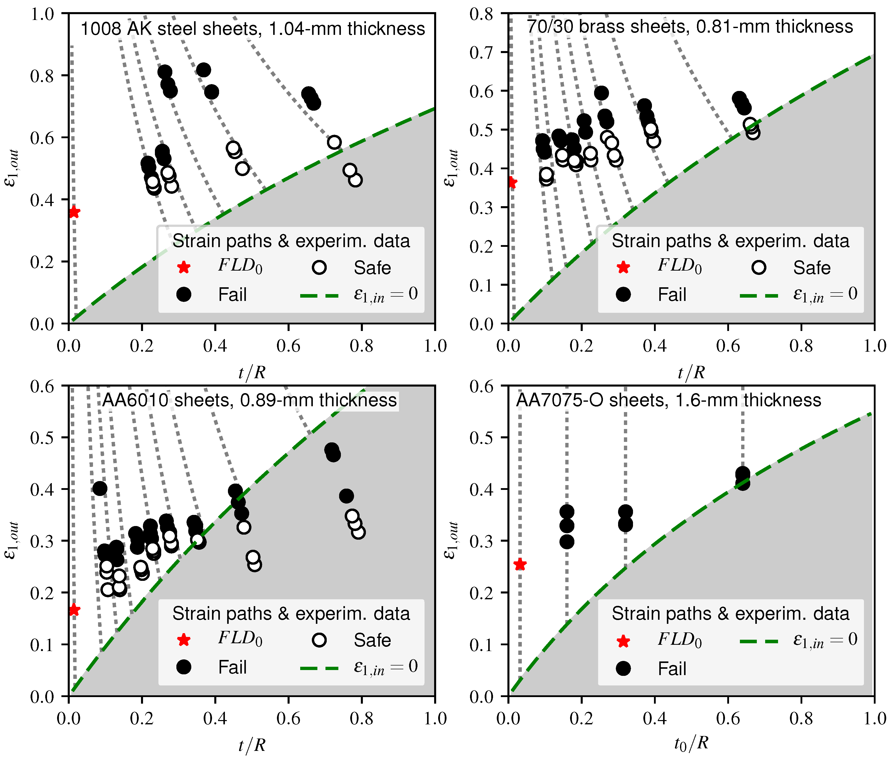
Figure 5 presents the experimental results provided in the mentioned references. Figure 5a–c depicts the major strains measured on the convex side of the sheet as a function of the current bending ratio . Instead, Figure 5d shows versus the initial bending ratio . The cases for which a visible neck was observed are represented as solid circles. Otherwise, open circles are used. The values of (see Table 1) are represented as solid stars.
Figure 5 also presents the strain paths predicted by the proposed stretch-bending deformation model for the different punch radii R. As can be observed, these agree reasonably well with the experimental results. The major differences are obtained by the largest values of , and they may be attributed to a potential indentation of the forming tool into the sheet thickness. In this situation, the transverse shear stress cannot be neglected, and the plane-section assumption in the deformed sheet element is no longer valid.
The shaded areas in Figure 5 and subsequent figures represent stretch-bending conditions for which the material in the inner side of the sheet was shortened, that is, . This situation inhibits the onset of the plastic instability, giving way to the eventual development of failure by ductile fracture at the outer side of the sheet. It should be noted that for 70/30 brass and 6010 aluminium sheets, the authors observed the initiation of cracks before necking for the largest values of . As can be observed, this observation agreed very well with the model predictions.
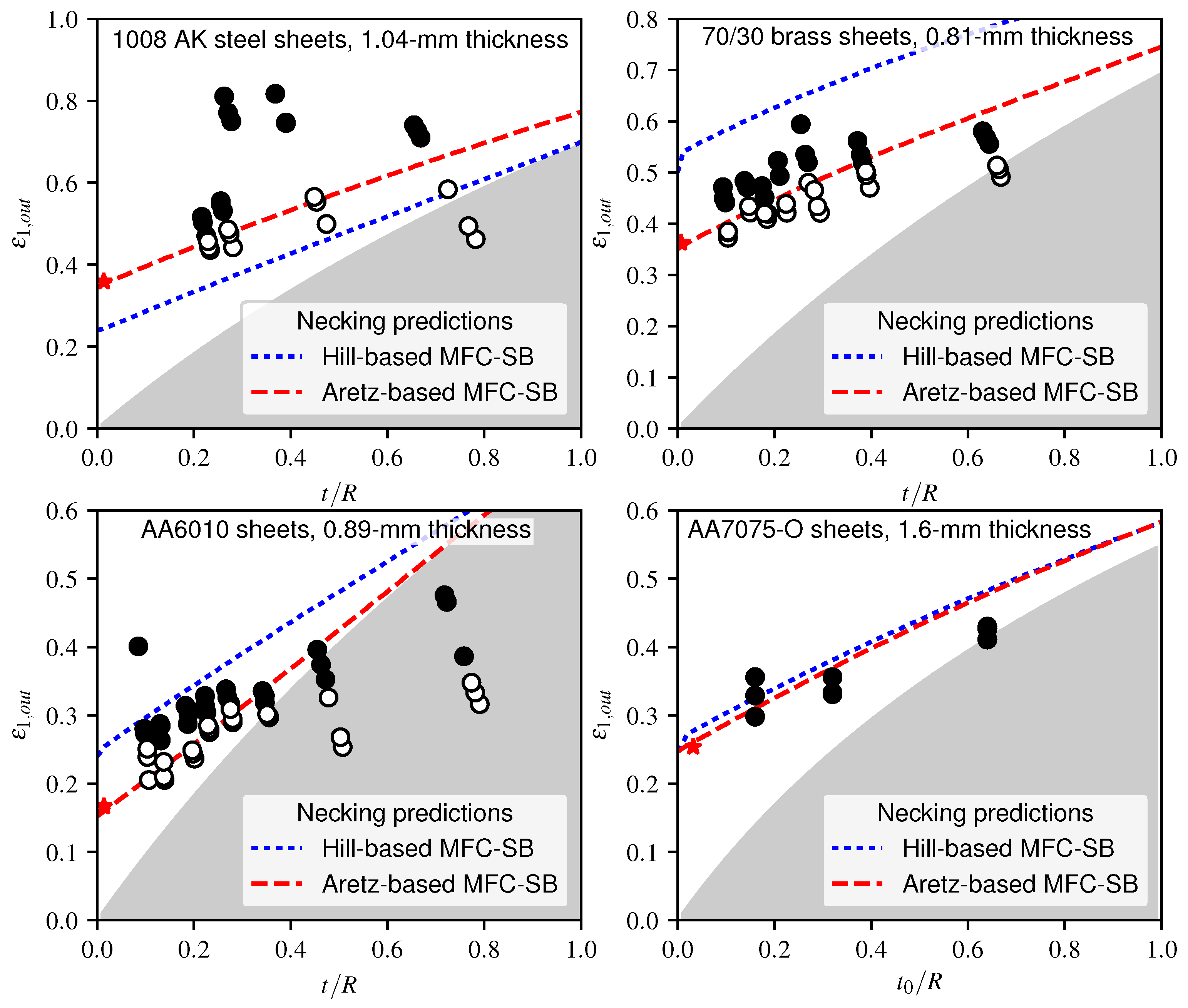
The value of the strains at the outer sheet surface predicted by Hill- and Aretz-based MFC-SB criteria at the onset of necking are represented in Figure 6. As can be seen, the Hill-based MFC-SB criterion given by Equation (27) underestimated the experimental results for 1008 AK steel sheets, whereas it overestimated these for 70/30 brass and 6010 aluminium sheets. Instead, the predictions of the Aretz-based MFC-SB (28) agreed very well with the experimental results for all materials analysed, except in general for the smallest punch radii.
It should be noted that both Hill- and Aretz-based MFC-SB criteria showed the same trend with the bending ratio. The basic difference was that the Aretz-based approach had been calibrated to meet the experimental value.
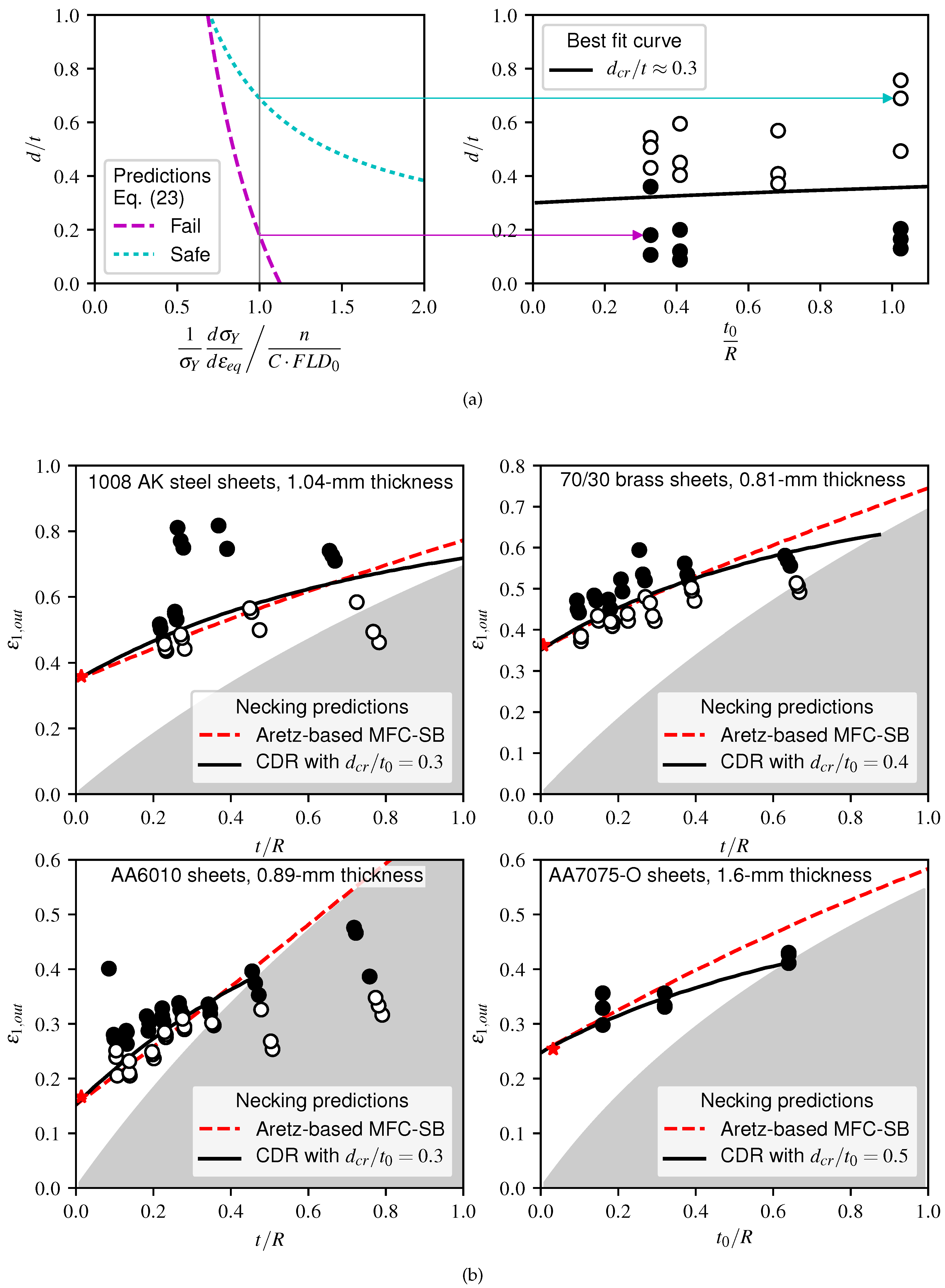
To assess the proposed CDR criterion, the critical distance on the sheet thickness was estimated for the different materials. Figure 7a reproduces graphically the calculation procedure to obtain for 1008 AK steel sheets. Figure 7a (left) shows the gradient through the sheet thickness of the local stability index based on the Aretz correction.
As can be seen, the distance d at which the value becomes equal to 1 was smaller in the failed specimen that in the successful specimen. This clearly indicates that the material volume resisting the necking of the sheet was smaller in the former than in the latter. Figure 7a (right) depicts the non-dimensional value for a local stability index equal to 1 versus the bending ratio for all tested specimens of 1008 AK steel. The almost horizontal line dividing successful tests from failures determines the value of the critical distance, which here is for the steel sheets. We note that the slight slope of the line is due to the material thickening as the sheet curvature increased.
In practice, it is enough to choose a few significant experimental data in the range of intermediate or high values of to determine the critical distance. The following values were obtained for the different materials: for 1008 AK steel and AA6010, for 70/30 brass and for AA7075-O sheets.
Figure 7b shows the necking predictions of the CDR criterion along with the Aretz-based MFC-SB discussed previously. In general, the CDR criterion improved the predictions over the whole range of values. As can be seen, for low values of , the slight improvement led to excellent predictions of experimental data of steel, brass and AA6010 sheets. However, for higher values of , the enhancements of predictions was clearly more pronounced, particularly in aluminium sheets.
7. Conclusions
The maximum force principle has been analysed to predict necking under stretch-bending conditions. Two kinds of failure criteria have been proposed, the first based on the generalisation of traditional MFCs to stretch-bending and the other based on the concept of damage in a critical material volume. The following conclusions can be drawn from this study:
- The strain-hardening function used to propose both types of failure criteria seems to control necking in both stretching and stretch-bending processes.
- The good results obtained by the proposed criteria are largely due to the calibration of the failure models from the experimental FLD in the absence of bending. Although the Aretz proposal for the modification of the Hill necking criterion under plane-strain conditions has been used in this work, the procedure can be generalised to the whole range of strain conditions in the FLD.
- The necking predictions of the proposed Aretz-based MFC-SB agree reasonably well with the experimental data. The lack of precision for high bending ratios seems to be related to the predictions of the deformation model rather than to the failure model itself.
- The necking predictions of the proposed CDR criterion fit well with the experimental data and improve those of the previous criterion over the whole range of values. To characterise the failure, a local stability index and a critical distance, which depends on the material, have been proposed. For the material analysed, the critical distance values range from 0.3 to 0.5. Although more exhaustive research is required to relate the critical distance to the material properties, this criterion can be easily implemented in the finite-element method.
Acknowledgments
The authors wish to thank the Spanish Government for its financial support throughout research project DPI2015-64047-R.
Author Contributions
Domingo Morales-Palma developed the analytical models, performed the simulations, analysed the results and wrote the paper; Andrés J. Martínez-Donaire provided support and contributed to the discussions; Carpóforo Vallellano provided support, analysed the results, contributed to the discussions and reviewed the paper.
Conflicts of Interest
The authors declare no conflict of interest.
Abbreviations
The following abbreviations are used in this manuscript:
| MFC | Maximum force criterion (Considère’s criterion) |
| FLD | Forming limit diagram |
| MFCs | Maximum force criteria (Considère’s criterion and related extensions and modifications: Swift, Hill, Hora, etc.) |
| MPR | Mid-plane rule |
| CSR | Concave-side rule |
| MFC-SB | Maximum force criterion generalised to stretch-bending processes |
| CDR | Critical-distance rule |
| lsi | Local stability index |
| CxSR | Convex-side rule |
Appendix A. Hosford Yield Criterion under Plane-Stress Condition
Assuming that the directions of principal stress coincide with the symmetry axis, the non-quadratic yield criterion proposed by Hosford for anisotropic materials [21] can be written as
where and are the Lankford coefficients along the rolling () and transverse () directions, respectively. This criterion reduces to the Hill quadratic yield criterion by setting . For isotropic materials (), it reduces to the Mises yield criterion by setting or , and to the Tresca criterion by setting or . The suggested values for the exponent are for BCC metals and for FCC materials. The ratios of the plastic strain increments are found from the flow rule as
The equivalent strain increment can be found from the plastic work as
Under plane-stress conditions through the sheet thickness (), it is usual to express the stress and strain increments by using the parameters , , , and . Thus, the equivalent stress and strain increments are given by the following [22]:
From the flow rule,
the following relation between and is established:
In the case of plane-strain conditions (), the and parameters are simplified to
As a check, particularising the above expression for Mises plasticity in plane stress, that is, by setting and , the parameters , , and yield
Appendix B. Hosford Yield Criterion under Plane-Strain Condition
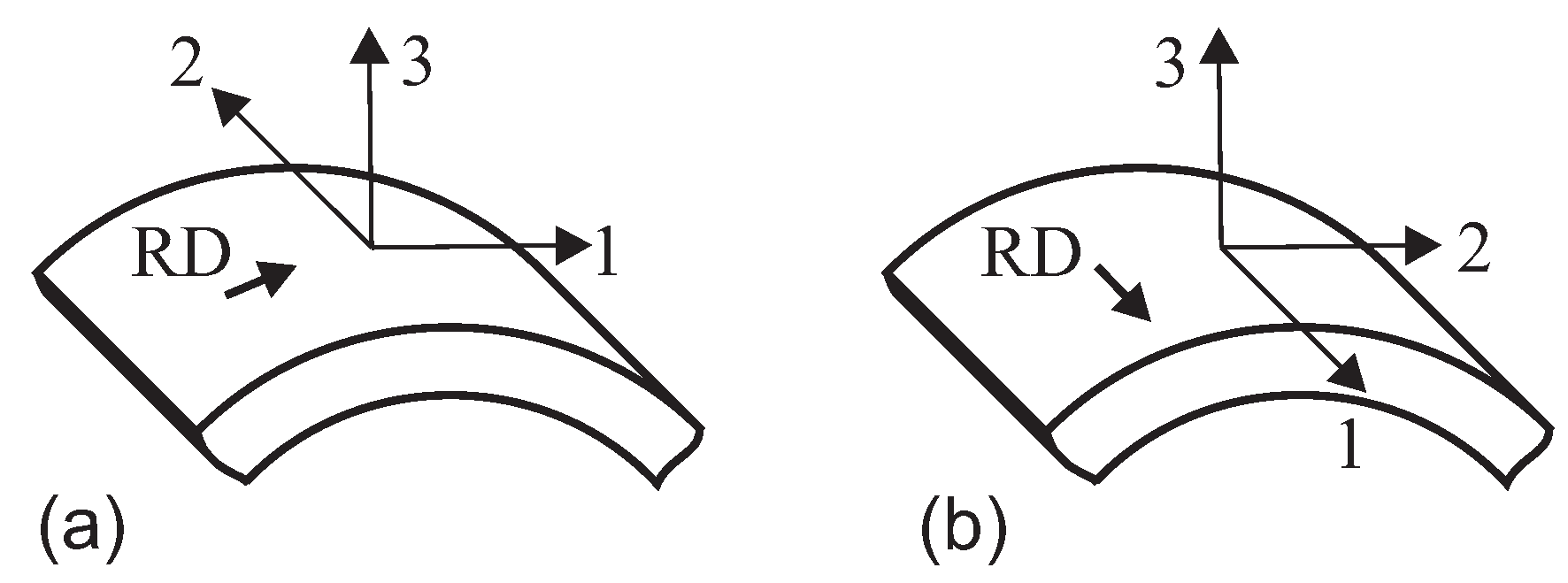
This following formulation is used to analyse the stretch-bending deformation model proposed in this paper. We consider a stretch-bent sheet in the rolling direction under plane-strain conditions () as represented in Figure A1a. From the flow rule given in Equation (A2), the stress in direction 2 is found as
Figure A1.
Stretch-bent metal sheet under plane-strain deformation: (a) ; (b) .

Substituting into Equation (A1), the equivalent stress reduces to
where C is found from the anisotropy parameters as
We note that the above expression matches in Equation (A9) for plane-stress conditions.
Setting in Equation (A3), the equivalent strain increment is expressed as
References
- Swift, H.W. Plastic instability under plane strain. J. Mech. Phys. Solids 1952, 1, 1–18. [Google Scholar] [CrossRef]
- Hill, R. On discontinuous plastic states, with special reference to localized necking in thin sheets. J. Mech. Phys. Solids 1952, 1, 19–30. [Google Scholar] [CrossRef]
- Hora, P.; Tong, L.; Reissner, J. A prediction method for ductile sheet metal failure using FE-simulation. In Proceedings of the NUMISHEET, Dearborn, MI, USA, 29 September–3 October 1996; pp. 252–256. [Google Scholar]
- Bressan, J.D.; Williams, J.A. The use of a shear instability criterion to predict local necking in sheet metal deformation. Int. J. Mech. Sci. 1983, 25, 155–168. [Google Scholar] [CrossRef]
- Hora, P.; Tong, L.; Berisha, B. Modified maximum force criterion, a model for the theoretical prediction of forming limit curves. Int. J. Mater. Form. 2013, 6, 267–279. [Google Scholar] [CrossRef]
- Brunet, M.; Morestin, F. Experimental and analytical necking studies of anisotropic sheet metals. J. Mater. Process. Technol. 2001, 112, 214–226. [Google Scholar] [CrossRef]
- Aretz, H. An extension of Hill’s localized necking model. Int. J. Eng. Sci. 2010, 56, 609–618. [Google Scholar] [CrossRef]
- Marciniak, Z.; Kuczyński, K. Limit strains in the processes of stretch-forming sheet metal. Int. J. Mech. Sci. 1967, 9, 609–620. [Google Scholar] [CrossRef]
- Tharrett, M.R.; Stoughton, T.B. Stretch-Bend Forming Limits of 1008 AK Steel; SAE Paper 2003-01-1157; Society of Automotive Engineers: Troy, MI, USA, 2003. [Google Scholar]
- Stoughton, T.B.; Yoon, J.W. A new approach for failure criterion for sheet metals. Int. J. Plast. 2011, 27, 440–459. [Google Scholar] [CrossRef]
- Morales-Palma, D.; Vallellano, C.; García-Lomas, F.J. Assessment of the effect of the through-thickness strain/stress gradient on the formability of stretch-bend metal sheets. Mater. Des. 2013, 50, 798–809. [Google Scholar] [CrossRef]
- Marciniak, Z.; Duncan, J.L.; Hu, S.J. Mechanics of Sheet Metal Forming, 2nd ed.; Butterworth-Heinemann: Oxford, UK, 2002. [Google Scholar]
- Aretz, H. Numerical analysis of diffuse and localized necking in orthotropic sheet metals. Int. J. Plast. 2007, 23, 798–840. [Google Scholar] [CrossRef]
- Abed-Meraim, F.; Balan, T.; Altmeyer, G. Investigation and comparative analysis of plastic instability criteria: Application to forming limit diagrams. Int. J. Adv. Manuf. Technol. 2014, 71, 1247–1262. [Google Scholar] [CrossRef] [Green Version]
- Stoughton, T.B.; Zhu, X. Review of theoretical models of the strain-based FLD and their relevance to the stress-based FLD. Int. J. Plast. 2004, 40, 1463–1486. [Google Scholar] [CrossRef]
- Martínez-Donaire, A.J.; Vallellano, C.; Morales, D.; García-Lomas, F.J. Experimental and numerical analysis of the failure of AA7075-O stretch-bend sheets. Steel Res. Int. 2012, 251–254. [Google Scholar]
- Hill, R. The Mathematical Theory of Plasticity; Clarendon Press: Oxford, UK, 1950. [Google Scholar]
- Morales, D.; Martínez-Donaire, A.J.; Vallellano, C.; García-Lomas, F.J. Bending effect in the failure of stretch-bend metal sheets. Int. J. Mater. Form. 2009, 2 (Suppl. S1), 813–816. [Google Scholar] [CrossRef]
- Vallellano, C.; Morales, D.; Martínez-Donaire, A.J.; García-Lomas, F.J. On the use of Concave-Side Rule and Critical-Distance Methods to predict the influence of bending on sheet-metal formability. Int. J. Mater. Form. 2010, 3 (Suppl. S1), 1167–1170. [Google Scholar] [CrossRef]
- Tharrett, M.R.; Stoughton, T.B. Stretch-Bend Forming Limits of 1008 AK Steel, 70/30 Brass, and 6010 Aluminum. In Dislocations, Plasticity and Metal Forming, Proceedings of the 10th International Symposium on Plasticity and Its Current Applications, Quebec, Canada, 7–11 July 2003; Neat Press: Jonesboro, AR, USA, 2003; pp. 199–201. [Google Scholar]
- Hosford, W.F. Mechanical Behavior of Materials; Cambridge University Press: Cambridge, UK, 2005. [Google Scholar]
- Hosford, W.F. Comments on anisotropic yield criteria. Int. J. Mech. Sci. 1985, 27, 423–427. [Google Scholar] [CrossRef]
- Tan, Z.; Persson, B.; Magnusson, C. Plastic bending of anisotropic sheet metals. Int. J. Mech. Sci. 1995, 37, 405–421. [Google Scholar] [CrossRef]
Figure 1.
Schema of a stretched element.
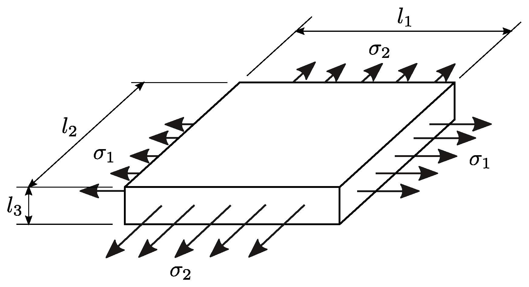
Figure 2.
Necking predictions for AA7075-O sheets: (a) critical values of , and (b) forming limit diagram (FLD) with necking curves and experimental data [16].
Figure 2.
Necking predictions for AA7075-O sheets: (a) critical values of , and (b) forming limit diagram (FLD) with necking curves and experimental data [16].

Figure 3.
Variables in a deformed sheet element.

Figure 4.
Critical-distance rule.
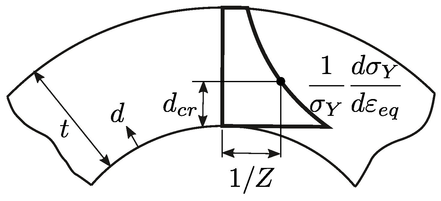
Figure 5.
Influence of punch radius R on the formability of stretch-bent 1008 AK steel, 70/30 brass, AA6010 and AA7075-O sheets.
Figure 5.
Influence of punch radius R on the formability of stretch-bent 1008 AK steel, 70/30 brass, AA6010 and AA7075-O sheets.

Figure 6.
Necking predictions of the proposed maximum force criterion in stretch-bending (MFC-SB) for stretch-bent 1008 AK steel, 70/30 brass, AA6010 and AA7075-O sheets.
Figure 6.
Necking predictions of the proposed maximum force criterion in stretch-bending (MFC-SB) for stretch-bent 1008 AK steel, 70/30 brass, AA6010 and AA7075-O sheets.

Figure 7.
Practical application of the proposed critical-distance rule (CDR) criterion. (a) Graphical representation for the calibration of the CDR (Equation (34)) for 1008 AK steel sheets: (left) predictions of the non-dimensional strain-hardening characteristic through the sheet thickness by Equation (23), illustrated for the experimental data of a failed and a successful specimen; (right) graphical determination of the critical distance as an almost horizontal line that separates failed from successful tests. (b) Necking predictions of proposed Aretz-based maximum force criterion in stretch bending (MFC-SB; Equation (28)) and CDR criterion (Equation (34)) for stretch-bent 1008 AK steel, 70/30 brass, AA6010 and AA7075-O sheets.

Table 1.
Mechanical properties and material constants.
| 1008 AK Steel | 70/30 Brass | AA6010 | AA7075-O | |
|---|---|---|---|---|
| (mm) | 1.04 | 0.81 | 0.89 | 1.6 |
| (MPa) | 187.0 | 112.5 | 202.0 | 102.3 |
| K (MPa) | 556.8 | 809.1 | 543.9 | 400.3 |
| n | 0.24 | 0.50 | 0.24 | 0.25 |
| 1.740 | 0.870 | 1.590 | 0.812 | |
| 1.800 | 0.730 | 1.760 | 1.317 | |
| a | 6 | 8 | 8 | 8 |
| 0.358 | 0.358 | 0.166 | 0.251 |
© 2017 by the authors. Licensee MDPI, Basel, Switzerland. This article is an open access article distributed under the terms and conditions of the Creative Commons Attribution (CC BY) license (http://creativecommons.org/licenses/by/4.0/).
Share and Cite
MDPI and ACS Style
Morales-Palma, D.; Martínez-Donaire, A.J.; Vallellano, C. On the Use of Maximum Force Criteria to Predict Localised Necking in Metal Sheets under Stretch-Bending. Metals 2017, 7, 469. https://doi.org/10.3390/met7110469
AMA Style
Morales-Palma D, Martínez-Donaire AJ, Vallellano C. On the Use of Maximum Force Criteria to Predict Localised Necking in Metal Sheets under Stretch-Bending. Metals. 2017; 7(11):469. https://doi.org/10.3390/met7110469
Chicago/Turabian StyleMorales-Palma, Domingo, Andrés J. Martínez-Donaire, and Carpóforo Vallellano. 2017. "On the Use of Maximum Force Criteria to Predict Localised Necking in Metal Sheets under Stretch-Bending" Metals 7, no. 11: 469. https://doi.org/10.3390/met7110469
Note that from the first issue of 2016, this journal uses article numbers instead of page numbers. See further details here.