Structure and Martensitic Transformation in Rapidly Solidified CoNiAlFe Alloy


1
School of Mechanical Engineering, Southeast University, Nanjing 211189, China
2
Jiangsu Key Laboratory of Advanced Structural Materials and Application Technology, School of Materials Engineering, Nanjing Institute of Technology, Nanjing 211167, China
3
Hangzhou Kaierda Electric Welder Co., Ltd., Hangzhou 310000, China
4
College of Mechanics and Materials, Hohai University, Nanjing 211100, China
5
Zhongtian Alloy Technology Co., Ltd., Nantong 226010, China
*
Authors to whom correspondence should be addressed.
Metals 2017, 7(11), 473; https://doi.org/10.3390/met7110473
Submission received: 19 September 2017
/
Revised: 30 October 2017
/
Accepted: 31 October 2017
/
Published: 3 November 2017
Abstract
:Housler based magnetic controlled shape memory alloys are characterized by a large magnetic field induced strain. The strain was dependent on the twin martensite structure rearrangement, and the rapid solidification technology had a significant influence on the microstructure, physical, and chemical properties of the alloy. Thus, the structure and the martensitic transformation changes of Co33Ni31Al27Fe9 during the rapidly solidified process were studied. The microstructure of Co33Ni31Al27Fe9 with furnace cooled and rapid solidification (RS) constitutes a dual-phase structure, β phase and γ phase in a low cooling rate and martensite and γ phase in a high cooling rate. The γ phase at the grain boundaries reduced and became more fragile by raising the RC value. The one-step austenite-martensite phase transformation occurred during the process of heating and cooling. The phase transition temperature presents an increasing trend by rising the cooling rate, even to over the room temperature. Moreover, the martensite structure in Co33Ni31Al27Fe9 constitutes a typical L10-type twinning structure.
1. Introduction
In the past three decades, Housler based magnetic controlled shape memory alloys (MCMEA), such as Ni-Mn-Ga [1,2], Co-Ni-Ga [3,4], Ni-Fe-Ga [5,6], Ni-Mn-X (X = In, Sb, Al) [7,8], and Co-Ni-Al [9,10], have attracted much scientific attention as it concerns the sensors and actuators industry. These kinds of Housler alloys are characterized by the ability of creating a large magnetic field induced strain (MFIS) and their high response frequency under an external magnetic field (EMF) [11,12].
Among these Housler alloys, the Co-Ni-Al system represents a new kind of MCMEA since the first order martensitic transformation from a high temperature paramagnetic cubic austenite phase to a low temperature ferromagnetic tetragonal twin martensitic phase was observed by Oikawa in Co-Ni-Al alloy [13]. Additionally, recent studies [10,14,15] on Co-Ni-Al series alloys, revealed that a large output MFIS could be affected by two main parameters, including a suitable martensite structure and a large deformation drive force. As it concerns the first factor, the MFIS can be obtained due to the martensite twin boundaries rearrangement under EMF. This is due to the magnetic domains, which exist in twin martensite variants, migrated in parallel with EMF direction, which results in the martensite variants being rearranged. In addition, as it concerns the second factor, the drive force for MFIS can be controlled by saturation magnetization and magnetocrystalline anisotropy of alloy, as described by Handley [16] and Ju et al. [14].
Nevertheless, there are many techniques to obtain a suitable martensite structure and the large deformation drive force, such as alloying, heart treatment, rapid solidification (RS), and directional solidification [17,18]. For these techniques, RS, including suction casting and injection, represent one of important non-equilibrium processing technique, and it has been frequently employed to change the microstructure and enhance the alloy properties. When compared to conventional solidification (CS), RS demonstrates a higher cooling rate (RC, approximately 1 × 10⁴ K·s−1) than CS (less than 50 K·s−1), and this results on the microstructure, as long as on the physical and chemical properties of alloy, which present a significant change during RS processes [18,19,20].
In the current paper, the authors focused on the martensitic transformation changes of typical MCMEA Co33Ni31Al27Fe9 (this alloy established apparent MSIF under EMF) during rapidly solidified process. In particular, the changes of martensite structure, martensitic transformation temperature, and the thermal hysteresis during rapidly solidified process were investigated in detail. Moreover, the relationship between martensitic transformation and different cooling rate was defined.
2. Materials and Methods
MCMEA samples with the nominal composition Co33Ni31Al27Fe9 were prepared by high-pure metals (the purity of Co, Ni, Al, and Fe was more than 99.99%, produced by China New Metal Materials Technology Co., Ltd., Beijing, China) using an arc-melting furnace (WK II, SKY Technology Development Co., Ltd., Shenyang, Liaoning, China) at 1973 K in an inert atmosphere (pure argon). Then, both CS (CS process was carried out by furnace cooled) and RS (RS process was carried out by suction cast in water cooled thick copper mold and the size of samples after suction cast were 1 mm × 70 mm, 4 mm × 70 mm, 8 mm × 70 mm (diameter × length)) process were carried out. To avoid the melting loss, the high-pure metals with high melting point, like Co, Ni, and Fe, were prepared 5 at % more. The high-pure metals with a low melting point, like Al, were prepared 15 at % more. Annealing sample was carried out at 1400 K for 6 h with an inert atmosphere (pure argon).
The relation tween RC and suction cast diameter were determined according to the Equation (1) as suggested by Johnson [21] and Liu [20], and the RC values were calculated as listed in Table 1:
The microstructure morphology and the element distribution of samples were examined by FEI-Sirion200 type scanning electron microscopy (SEM, FEI, Hillsboro, OR, USA), equipped with an energy-dispersive X-ray spectrometry (EDS, Field Electron and Ion Company, Hillsboro, OR, USA) microanalysis system. The crystallographic phase identification was carried out by Philips PW170 type X-ray diffraction (XRD, Philips, Amstel dam, The Netherlands), with CuKα radiation source (λ = 1.5418 Å) in the 2θ range between 10°–90°. For fine bar shaped samples, a special testing mold (as seen in Figure 1) was used during the XRD test. The structure of martensite was determined by JOEL-2000EX type transmission electron microscopy (TEM, JOEL, Tokyo, Japan), and selected area electron diffraction patterns (SADP). Finally, the martensitic transformation temperature and thermal hysteresis of samples were analyzed by STA449 F3 type differential scanning calorimeter (DSC, Netzsch, Bavarian, Germany) and selected area electron diffraction patterns (SADP). Finally, the martensitic transformation temperature and thermal hysteresis of samples were analyzed by STA449 at the cooling and heating rate of 5 K·min−1.
3. Results
3.1. Microstructure
For MCMEA, a suitable microstructure constitutes one of the conditions to obtain MFIS and the microstructure can be formed by solidification processes and element composition [17]. Figure 2 demonstrates the microstructure detail of Co33Ni31Al27Fe9 alloy with furnace cooled and RS processes. For the furnace cooled sample (Figure 1a), a typical dual-phases structure consisted of the dark color parent phases, while the light color secondary phases can be observed. The secondary phases presented a continuous distribution and gathered in grain boundaries (the red circle in Figure 2a). For the RS sample, the microstructure of the sample with a lower RC value, preserved the light color secondary phases surrounding the dark color parent phases dual-phase structure, as seen in Figure 2b. However, the only difference is that the secondary phases no longer present a tendency to aggregate at the grain boundaries. By increasing the RC value, a significant change of microstructure occurred in the sample. The dark color parent phases vanished and were replaced by lath-shaped phases. Meanwhile, the light color continuous distribution secondary phases changed into fragmentary type at the grain boundaries as illustrated in Figure 2c. For the highest RC value, the lath-shaped phases represent the higher percentage of the area in Figure 2d. The light color secondary phases was further broken into smaller parts. After annealing, the sample consisted of both the parent phases and the secondary phases as seen in Figure 1e, which is identical to the microstructure of the sample with furnace cooled.
In order to obtain the difference between the desired composition and the actual composition of the sample, the ICP-MS test was carried out and the results list in Table 2. Actually, there is only a small error between the desired composition and the actual composition of the sample from Table 2. Each actual composition of the sample, including Furnace cooled, D8, D4, and D1, were very close to the Co33Ni31Al27Fe9.
To check the homogeneity and element distribution of final composition, EDS analysis of each sample has been carried out and the results are presented in Figure 3. The total scan area (yellow area in Figure 3) results confirm that the melting loss remained within reasonable limits and the composition of the sample (32.89~33.76 at % Co-30.30~32.54 at % Ni-25.10~27.66 at % Al-8.28~9.47 at % Fe) had a good agreement with the nominal compositions (33 at % Co-31 at % Ni-27 at % Al-9 at % Fe). Furthermore, the element distribution at different phases (the present phase, the secondary phase and the lath-shaped phase) of samples was also defined. The present phases (red area in Figure 3) of the furnace cooled sample and D8 (with lower RC value) were found to include the same atomic ratio of elements Co, Ni, and Al (approximates to 1:1:1), but only a limited amount of element Fe. By comparing the secondary phases in furnace cooled sample and D8, they contain a high amount of element Co and Fe and less element Ni and Fe. When the RC reached a higher value (D4 and D1), a significant trend of elemental reduction of Co and Fe content in the secondary phases appeared. Additionally, the Co and Fe content in the lath-shaped phase maintain an increasing trend with RC being a rising value. This indicated that the elements of Co and Fe can gradually move towards the matrix when the RC value increases. EDS line scanning of lath-shaped phase was shown in Figure 3e. As can be seen that Co, Ni, Al, and Fe content was stablein whole lath-shaped phase, indicated that the elements in lath-shaped phase were in homogeneous distribution.
The XRD patterns of the Co33Ni31Al27Fe9 alloy with furnace cooled and RS at room temperature are illustrated in Figure 4. It is demonstrated that there were two phases in both the furnace cooled and RS samples, including β and γ phase in furnace cooled sample and D8, martensite and γ phase in D4 and D1, which has a good agreement with the observed in SEM analysis. The main diffraction peaks of furnace cooled sample (Figure 4a) were located at 35.6°, 48.3°, 56.1°, 70.6°, 74.8°, and 86.9°, were indexed in β phase (B2 structure) and γ phase (A1 structure) mixture. Furthermore, some peaks were sharp presenting high intensity. In the RS process with a lower RC value (Figure 4b), there were still two phases (β phase + γ phase) including some sharp peaks, and high intensity was observed at the same degrees. When combined with SEM analysis, it can be deduced that B2 structure β phase and A1 structure γ phase should correspond to the present and the secondary phase, respectively. When the RC value increased further (Figure 4c), the peaks for β phase disappeared. Nevertheless, some new peaks, which indexed to L10 structure martensite phase and γ phase, arose at 43.2°, 48.3°, 49.8°, 57.1°, 67.5°, and 74.8°, indicated that the lath-shaped phase, which was observed in Figure 1c,d, could be the martensite. When the RC value reached the maximum (Figure 4d), the sample maintained a mixture of the martensite phase and γ phase and the diffraction peak appeared the broad scattering peaks. Moreover, a cubic β phase was detected at room temperature, demonstrating that the martensitic transformation should have occurred below room temperature (in the furnace cooled sample and D8). Conversely, the tetragonal martensite phase was discovered at room temperature, indicating that the martensitic transformation occurred above room temperature (in D4 and D1).
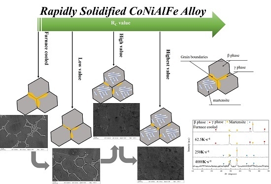
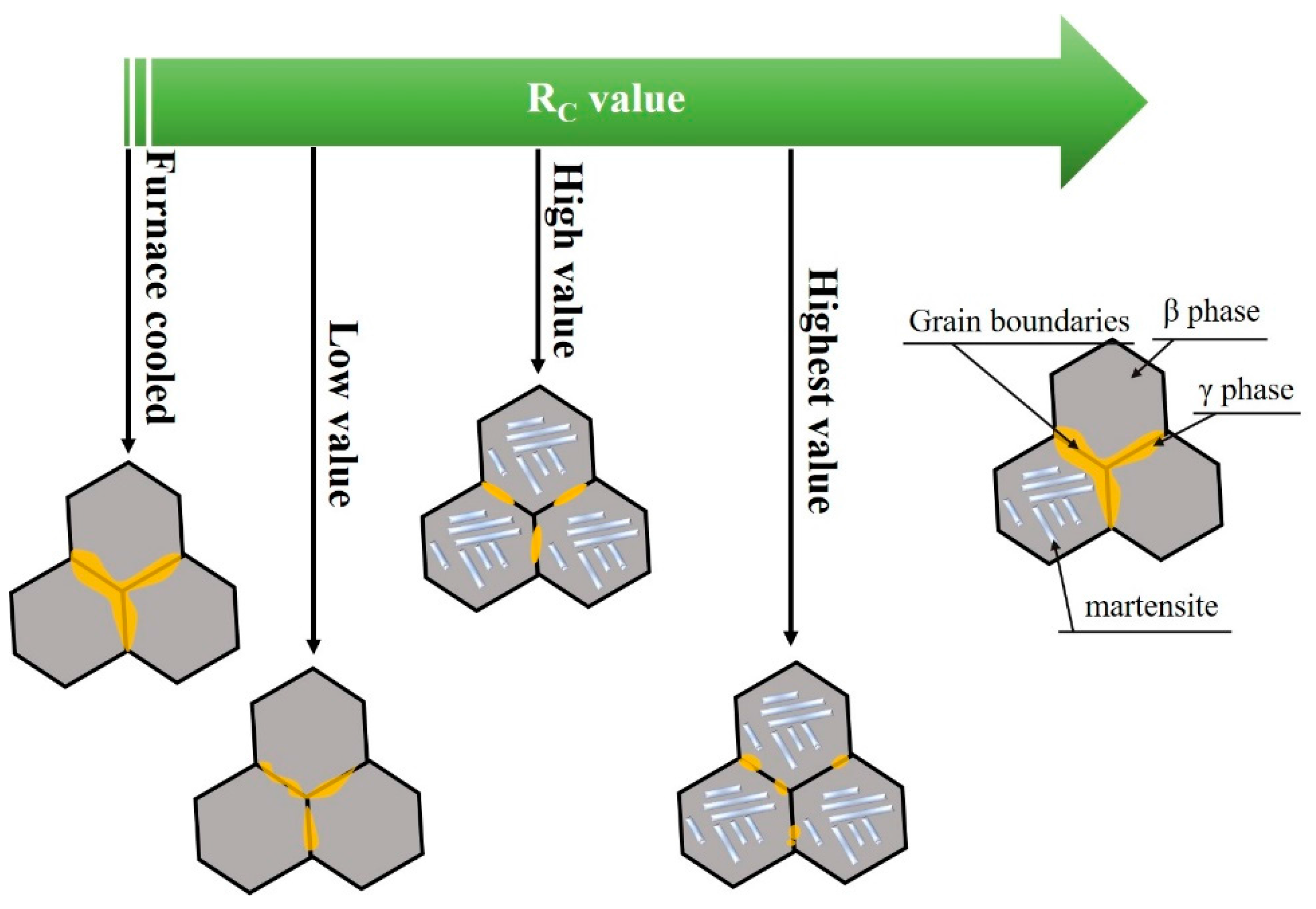
Usually, the morphology of microstructures and elemental distribution are sensitive to the solidification process, including the solidification mode and solidification condition [18]. The experimental conditions and the obtained phases of the Co33Ni31Al27Fe9 alloy with furnace cooled and RS are shown in Table 2. According the data in Table 3, the solidification process depends on the RC value, which can be represented by the model illustrated in Figure 5. In this figure, the solidification process of MCMEA can be divided into three classes when the RC fluctuates from low to high values.
Analysis of the first class (low RC value, RC < 100 K·s−1):
At the solidification in a low RC value, similar furnace cooled sample and D8, the liquid state alloy has more available time to solidify, and the secondary phase has more available time to precipitate at the grain boundaries. Thus, the microstructure appears the continuous secondary phase surrounding the parent phase. As the RC value slightly rose (D8), the secondary phase at the grain boundaries became refined due to less available solidification time in D8.
Analysis of the second class (medium RC value, 100 K·s−1 < RC < 1000 K·s−1):
When the RC corresponded to a medium value, the liquid state alloy obtained a high super-cooling during solidification process and the secondary phase re-melting and fragmenting occurred, by the mechanism of RS fragmenting. On the contrary, a higher solidification speed can reduce the solidification time during solidification process and result in less creation of the secondary phase at the grain boundaries.
Analysis of the third class (high RC value, RC > 1000 K·s−1):
When the RC value increases above 1000 K·s−1, during the solidification process, the third-class form occurred. A higher degree of super-cooling further intensified the secondary phase re-melting and fragmenting into a smaller part. On the contrary, the short solidification time is responsible for the reduced secondary phases arising in the alloy.
3.2. Martensitic Transformation
According to the XRD analysis, the temperature for the DSC scans of furnace cooled sample and D8 should be heating form below room temperature to test for the martensitic transformation temperature. Likewise, for D4 and D1, the temperature for DSC scans should be heating from room temperature. Figure 6 corresponds to the DSC curve of Co33Ni31Al27Fe9 alloy, including furnace cooled and RS. It is demonstrated that only one distinct endothermic and exothermic peak of DSC curve occurred during the heating and cooling processes. Thus, the phase transformation was a typical one-step phase transformation during heating and cooling. The austenite-martensite phase transformation temperature [martensite start temperature (TMs), martensite finish temperature (TMf), austenite start temperature (TAs), and austenite finish temperature (TAf)] were analyzed by the tangent method from DSC curves. The phase transformation temperature of the sample with a lower RC value (such as furnace cooled sample and D8) was below the room temperature (≤300 K). The sample with the increased RC value, presented a phase transformation temperature close to the room temperature (D4), even when higher than the room temperature (D1). For MCMEA, a higher phase transformation temperature (over room temperature) could significantly promote the application of this alloy in the field of the sensors and actuators industry.
Furthermore, an apparent thermal hysteresis was observed during the heating and cooling process. The thermal hysteresis value (ΔT) can be calculated by the equation: ΔT = TAs − TMf. The values of thermal hysteresis equaled approximately 11.8, 4.5, 2.3, and 0.7 K for furnace cooled sample, D8, D4, and D1, respectively. The width of the thermal hysteresis, which presented a continuous reduction, may be caused by the change of the elastic and surface energies during martensitic transformation with the rising RC value [22].
In recent reports, Sanchez et al. [23] and Jia et al. [24] indicated that the martensitic transformation temperature in Housler alloys proved to be very sensitive to the valence electron concentration (Re/a). In dual-phases structure MCMEA, only the ferromagnetic twin martensitic can obtain the MFIS by EMF, while the γ cannot participate in this process. The element distribution of β phase or martensite has clear distinction with different RC value. Hence, to illustrate the reason of martensitic transformation temperature change, the Re/a value of β phase and martensite can be calculated by Equation (1), and the results are illustrated in Figure 7.
where, ai and bi correspond to the atomic valence electron and the proportion of element i, respectively. The atomic valence electron for Co, Ni, Al and Fe were 9, 10, 3 and 8, respectively.
Re/a = Σ(ai × bi)
According to Figure 7, it is concluded that the Re/a value of martensite in Co33Ni31Al27Fe9 alloy had a significant increasing tendency as the RC was rising. For the furnace cooled sample, the RC value is the minimum when compared with RS sample and the Re/a value, which was calculated from the element content, corresponded to the minimum also. By raising the RC value, the Re/a value initially slightly increased (from furnace cooled rise to 62.5 K·s−1), and subsequently increased rapidly (from 62.5 K·s−1 rise to 250 K·s−1), while at the last stage it increased slowly (from 250 K·s−1 rise to 4000 K·s−1). An explanation of this “slow-rapid-slow” rising phenomenon can be ascribed to the element distribution of alloy including RC value effects similar to the analysis in the EDS part. This results in a satisfying agreement, with the report presented by Rekik et al. [22].
Another reason for martensitic transformation temperature and thermal hysteresis change is the distribution of elements changes. According to the RS process, the element content of Ni and Al in martensite consistently decreasing, but Co and Fe rising. Although the increase of Co content can result in the martensitic transition temperature decreasing, nevertheless, the rising of the Fe content and the decreasing of Ni and Al can greatly ascend the martensitic transition temperature and decrease the thermal hysteresis. So, the martensitic transition temperature keeps ascending and the thermal hysteresis reduces gradually during the RS process.
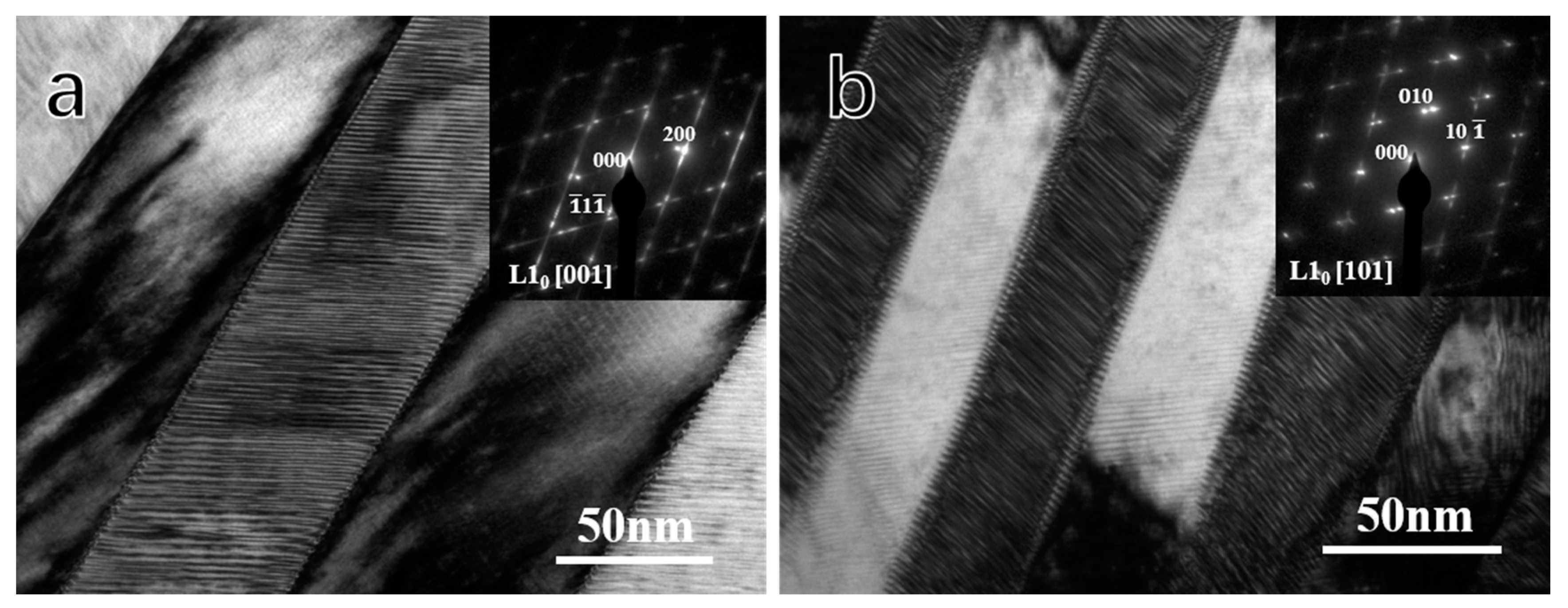
The morphology details and the structure of martensite of D4, and D1 was determined by TEM and SADP analysis (Figure 8). However, the lath-shaped martensite in both D4 and D1, contained numerous black and white stripes alternating presence, which exhibited a typical twinning structure. The twin martensite boundaries aligned at approximately ±45° including twin boundaries. Moreover, the SADP of the martensite twin structure along the [001] m zone axis in D4 and the [101] m zone axis in D1 had presented dual-sets of overlapping diffraction patterns (ODP), as illustrated in the top right corner in Figure 8. The dual-sets ODP in both D4 can be indexed by the L10 structure with a = b = 0.382 nm, c = 0.321 nm. Additionally, in D1, the ODP can be indexed by the L10 structure with a = b = 0.376 nm, c = 0.325 nm, which compromises with the XRD analysis.
4. Conclusions
In this paper, authors attempted to reveal the structure and martensitic transition change during the RS process. Thus, the changes of martensite structure, martensitic transformation temperature, and the thermal hysteresis during the rapidly solidified process were investigated in detail and the main conclusions are as follows:
- (1)
- The microstructure of Co33Ni31Al27Fe9 alloy with furnace cooled and RS corresponded to a dual-phase structure, β phase + γ phase in furnace cooled sample, and D8; martensite + γ phase in D4 and D1. The γ phase at the grain boundaries tended to be limited and more fragile, when the RC value was raised.
- (2)
- By increasing the RC value, the elements Co and Fe in Co-rich γ phase presented apparent trend diffusion to the β phase and martensite.
- (3)
- The martensite structure of D4 corresponded to the L10 structure with a = b = 0.382 nm, c = 0.321 nm and in D1, the martensite equaled the L10 structure with a = b = 0.376 nm, c = 0.325 nm.
- (4)
- The one-step austenite-martensite phase transformation occurred during the process of heating and cooling. The phase transition temperature preserved a significant tendency of increasing with the rise of the RC value, even over the room temperature in D1. Additionally, the values of thermal hysteresis were about 11.8, 4.5, 2.3, and 0.7 K for furnace cooled sample, D8, D4, and D1, respectively.
Acknowledgments
This work is supported by the Scientific Foundation of Nanjing Institute of Technology (Project No. YKJ201504), the Opening Project of Jiangsu Key Laboratory of Advanced Structural Materials and Application Technology (Project No. ASMA201609), the Natural Science Foundation of Jiangsu Province of China (Project No. BK20160869), Basic research project of Nanjing Institute of Technology (Project No. JCYJ201605), the National Natural Science Foundation of China (Project No. 61175069) and Outstanding Scientific and Technological Innovation Team in Colleges and Universities of Jiangsu Province.
Author Contributions
Jia Ju, Liguo Shuai and Huiling Chen conceived and designed the experiments; Huan Liu, Liguo Shuai and Huiling Chen performed the experiments; Huan Liu, Chen Yan and Zhuang Liu contributed materials; Liguo Shuai, Huiling Chen and Huan Liu analyzed the data; Jia Ju, Liguo Shuai and Huiling Chen wrote the paper. All authors have discussed the results, read and approved the final manuscript.
Conflicts of Interest
The authors declare no conflict of interest.
References
- Zhou, L.; Schneider, M.M.; Giri, A.; Cho, K.; Sohn, Y. Microstructural and crystallographic characteristics of modulated martensite, non-modulated martensite, and pre-martensitic tweed austenite in Ni-Mn-Ga alloys. Acta Mater. 2017, 134, 93–103. [Google Scholar] [CrossRef]
- Dai, Y.C.; Hou, L.; Fautrelle, Y.; Li, Z.B.; Esling, C.; Ren, Z.M.; Li, X. Martensitic transformation and detwinning in directionally solidified two-phase Ni-Mn-Ga alloys under uniaxial compression. J. Alloys Compd. 2017, 722, 721–728. [Google Scholar] [CrossRef]
- Mino, J.; Ipatov, M.; Gamcova, J.; Saksl, K.; Durisin, M.; Zhukova, V.; Vargova, Z.; Zhukov, A.; Varga, R. Magnetic Characterization of Melt-Spun Co-Ni-Ga Ferromagnetic Superelastic Alloy. Acta Phys. Pol. A 2017, 131, 1075–1077. [Google Scholar] [CrossRef]
- Vollmer, M.; Krooss, P.; Segel, C.; Weidner, A.; Paulsen, A.; Frenzel, J.; Schaperc, M.; Eggeler, G.; Maier, J.H.; Niendorfa, T. Damage evolution in pseudoelastic polycrystalline Co-Ni-Ga high-temperature shape memory alloys. J. Alloys Compd. 2015, 633, 288–295. [Google Scholar] [CrossRef]
- Timofeeva, E.E.; Panchenko, E.Y.; Chumlyakov, Y.I.; Maier, H.J.; Gerstein, G. Peculiarities of High-Temperature Superelasticity in Ni-Fe-Ga Single Crystals in Compression. Tech. Phys. Lett. 2017, 43, 320–323. [Google Scholar] [CrossRef]
- Chabungbam, S.; Borgohain, P.; Ghosh, S.; Singh, N.; Sahariah, M.B. Martensitic transformation and magnetism in Ni and Fe-rich compositions of Ni-Fe-Ga shape memory alloys. J. Alloys Compd. 2016, 689, 199–207. [Google Scholar] [CrossRef]
- Sharma, J.; Suresh, K.G. Investigation of multifunctional properties of Mn50Ni40−xCoxSn10 (x = 0–6) Heusler alloys. J. Alloys Compd. 2015, 620, 329–336. [Google Scholar] [CrossRef]
- Liu, J.; Fei, X.P.; Gong, Y.Y.; Xu, F. Phase Transition and Magnetocaloric Properties of Ni50Mn35-xIn15Cux Bulk Alloys and Ribbons. IEEE Trans. Magn. 2015, 51. 2503004. [Google Scholar] [CrossRef]
- Ju, J.; Yang, L.; Hao, S.; Mao, Q.T.; Lou, S.T.; Liu, H. Microstructure Martensite Transition and Mechanical Properties Investigations of Polycrystalline Co-Ni-Al Alloys with Er Doping. J. Mater. Eng. Perform. 2017, 26, 1062–1068. [Google Scholar] [CrossRef]
- Yamakov, V.; Hochhalter, J.D.; Leser, W.P.; Warner, J.E.; Newman, J.A.; Pun, G.P.P.; Mishin, Y. Multiscale modeling of sensory properties of Co-Ni-Al shape memory particles embedded in an Al metal matrix. J. Mater. Sci. 2016, 51, 1204–1216. [Google Scholar] [CrossRef]
- Li, P.Z.; Karaca, H.E.; Chumlyakov, Y.I. Orientation dependent compression behavior of Co35Ni35Al30 single crystals. J. Alloys Compd. 2017, 718, 326–334. [Google Scholar] [CrossRef]
- Kokorin, V.V.; Konoplyuk, S.M.; Dalinger, A.; Maier, H.J. Influence of martensitic transformation on the magnetic transition in Ni-Mn-Ga. J. Magn. Magn. Mater. 2017, 432, 266–270. [Google Scholar] [CrossRef]
- Oikawa, K.; Wulff, L.; Iijima, T.; Gejima, F.; Ohmori, T.; Fujita, A.; Fukamichi, K.; Kainuma, R.; Ishida, K. Promising ferromagnetic Ni-Co-Al shape memory alloy system. Appl. Phys. Lett. 2001, 79, 3290–3292. [Google Scholar] [CrossRef]
- Ju, J.; Lou, S.T.; Yan, C.; Yang, L.; Li, T.; Hao, S.; Wang, X.Y.; Liu, H. Microstructure Magnetism and Magnetic Field Induced-Strain in Er-Doped Co-Ni-Al Polycrystalline Alloy. J. Electron. Mater. 2017, 46, 2540–2547. [Google Scholar] [CrossRef]
- Ju, J.; Xue, F.; Li, H. Microstructure and Magnetic Property Variation with Addition of Rare Earth Element Dy in Co-Ni-Al Ferromagnetic Shape Memory Alloy. J. Iron Steel Res. Int. 2015, 22, 858–863. [Google Scholar] [CrossRef]
- O’Handley, R.C. Model for strain and magnetization in magnetic shape-memory alloys. J. Appl. Phys. 1998, 83, 3263–3270. [Google Scholar] [CrossRef]
- Olszewski, J.; Zbroszczyk, J.; Hasiak, M.; Kaleta, J.; Nabialek, M.; Bragiel, P.; Sobczyka, K.; Ciurzyńska, W.; Świerczek, J.; Łukiewskaa, A. Microstructure and magnetic properties of Fe-Co-Nd-Y-B alloys obtained by suction casting method. J. Rare Earths 2009, 27, 680–683. [Google Scholar] [CrossRef]
- Ju, J.; Xue, F.; Sun, L.X. Effect of Rapid Solidification on the Microstructure and Magnetic-Field-Induced Strain of Co1.36Ni1.21AlFe0.12. Mater. Manuf. Process. 2015, 30, 637–643. [Google Scholar] [CrossRef]
- Zhou, T.; Yang, M.B.; Zhan, J.; Peng, C.Y.; Hu, J.J.; Chen, K.; Zhou, Z.; Chen, Z.H. Investigation on the Microstructure Characterization and Aging Response of Rapidly Solidified Mg-6wt%Zn-5wt%Ca Alloy Produced by Atomization-Twin Roll Quenching Technology. Mater. Manuf. Process. 2012, 27, 125–129. [Google Scholar] [CrossRef]
- Liu, J.; Li, J.G. Microstructure, shape memory effect and mechanical properties of rapidly solidified Co-Ni-Al magnetic shape memory alloys. Mater. Sci. Eng. A 2007, 454, 423–432. [Google Scholar] [CrossRef]
- Lin, X.H.; Johnson, W.L. Formation of Ti-Zr-Cu-Ni bulk metallic glasses. J. Appl. Phys. 1995, 78, 6514–6519. [Google Scholar] [CrossRef]
- Rekik, H.; Krifa, M.; Bachaga, T.; Escoda, L.; Sunol, J.J.; Khitouni, M.; Chmingui, M. Structural and martensitic transformation of MnNiSn shape memory alloys. Int. J. Adv. Manuf. Technol. 2017, 90, 291–298. [Google Scholar] [CrossRef]
- Sanchez-Alarcos, V.; Recarte, V.; Perez-Landazabal, J.I.; Gomez-Polo, C.; Rodriguez-Velamazan, J.A. Role of magnetism on the martensitic transformation in Ni-Mn-based magnetic shape memory alloys. Acta Mater. 2012, 60, 459–468. [Google Scholar] [CrossRef]
- Ju, J.; Lou, S.T.; Yang, L.; Li, T.; Hao, S.; Yan, C. Effect of Electronic and Magnetic Valences on Phase Transition and Magnetic Properties in Co-Ni-Al-RE (RE = Gd, Dy and Er) Alloys. J. Electron. Mater. 2017, 46, 1390–1395. [Google Scholar] [CrossRef]
Figure 1.
Schematic diagram of the X-ray diffraction (XRD) testing mold.
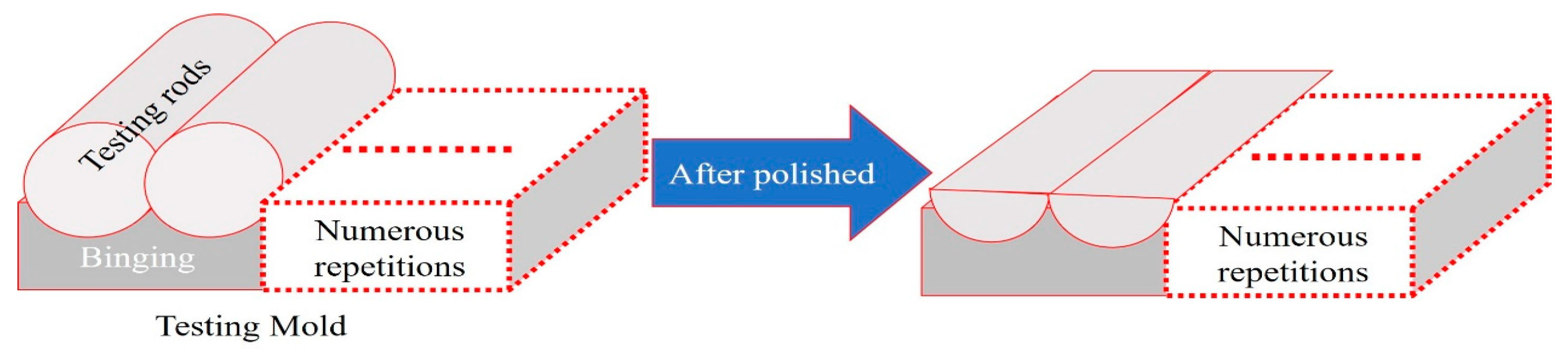
Figure 2.
Morphology of microstructures in Co33Ni31Al27Fe9 alloy with furnace cooled and rapid solidification (RS): (a) furnace cooled; (b) D8; (c) D4; (d) D1; and (e) the sample after annealing.
Figure 2.
Morphology of microstructures in Co33Ni31Al27Fe9 alloy with furnace cooled and rapid solidification (RS): (a) furnace cooled; (b) D8; (c) D4; (d) D1; and (e) the sample after annealing.

Figure 3.
The X-ray spectrometry test of of the Co33Ni31Al27Fe9 alloy with furnace cooled and RS: (a) furnace cooled; (b) D8; (c) D4; (d) D1; (e) EDS line scanning of lath-shaped phase.
Figure 3.
The X-ray spectrometry test of of the Co33Ni31Al27Fe9 alloy with furnace cooled and RS: (a) furnace cooled; (b) D8; (c) D4; (d) D1; (e) EDS line scanning of lath-shaped phase.
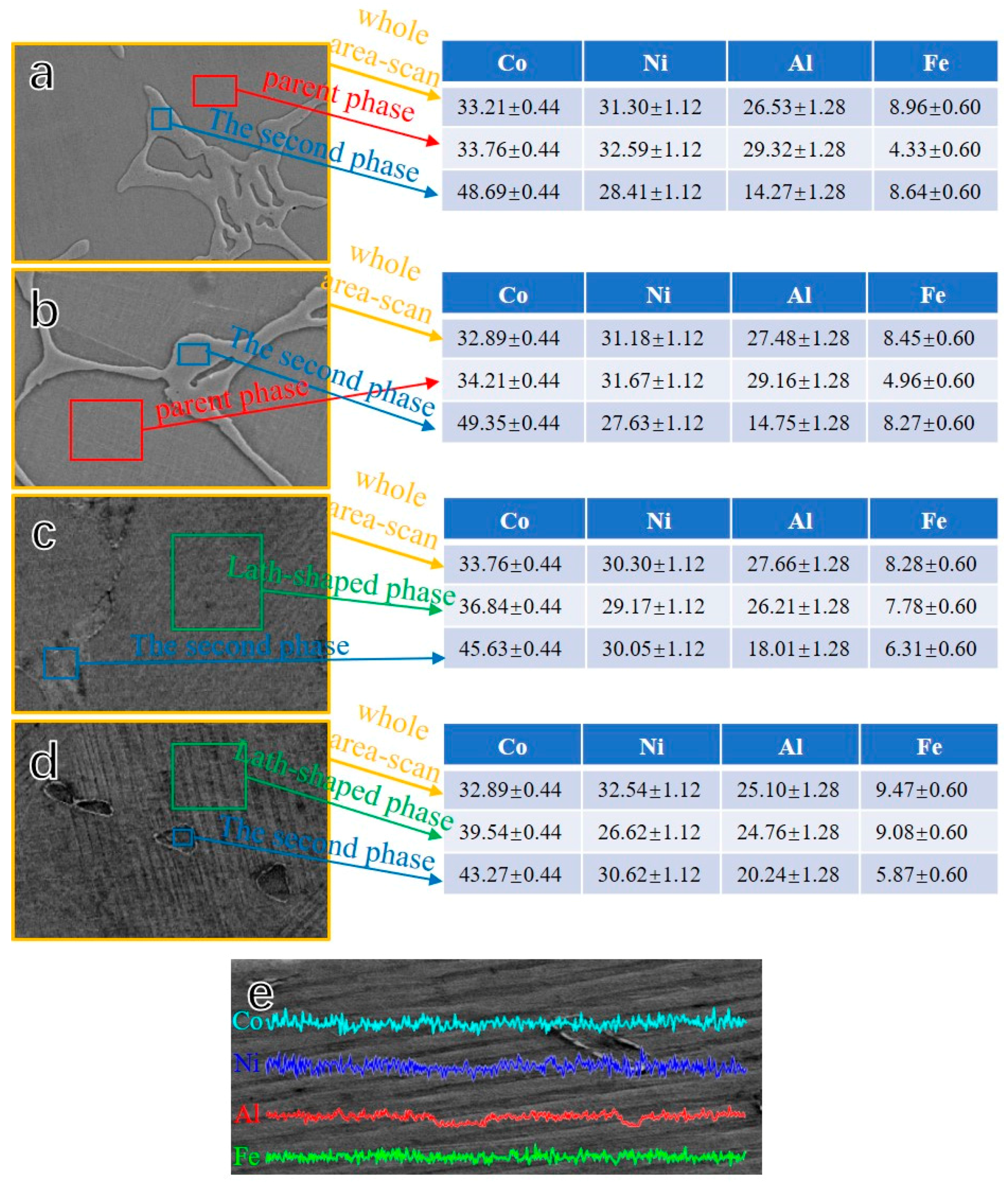
Figure 4.
Room temperature XRD patterns of the Co33Ni31Al27Fe9 alloy with furnace cooled and RS: (a) furnace cooled; (b) D8; (c) D4; and (d) D1.
Figure 4.
Room temperature XRD patterns of the Co33Ni31Al27Fe9 alloy with furnace cooled and RS: (a) furnace cooled; (b) D8; (c) D4; and (d) D1.
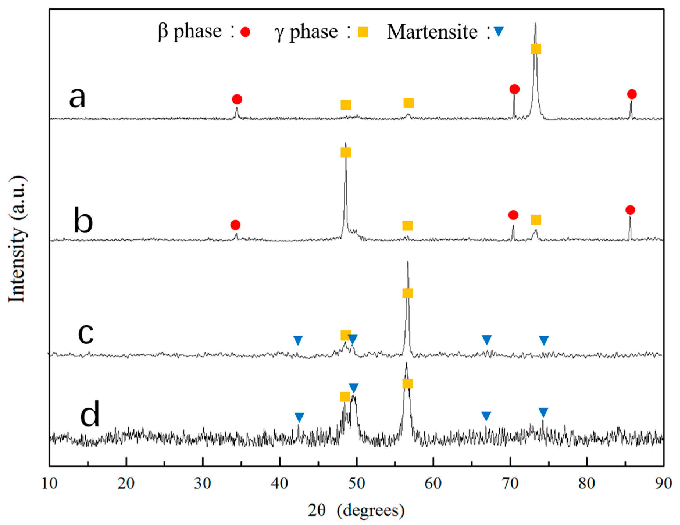
Figure 5.
The schematic of the microstructural changes during the various RS processes.

Figure 6.
Differential scanning calorimeter (DSC) curve of Co33Ni31Al27Fe9 alloy with furnace cooled and RS: (a) furnace cooled; (b) D8; (c) D4; and (d) D1.
Figure 6.
Differential scanning calorimeter (DSC) curve of Co33Ni31Al27Fe9 alloy with furnace cooled and RS: (a) furnace cooled; (b) D8; (c) D4; and (d) D1.
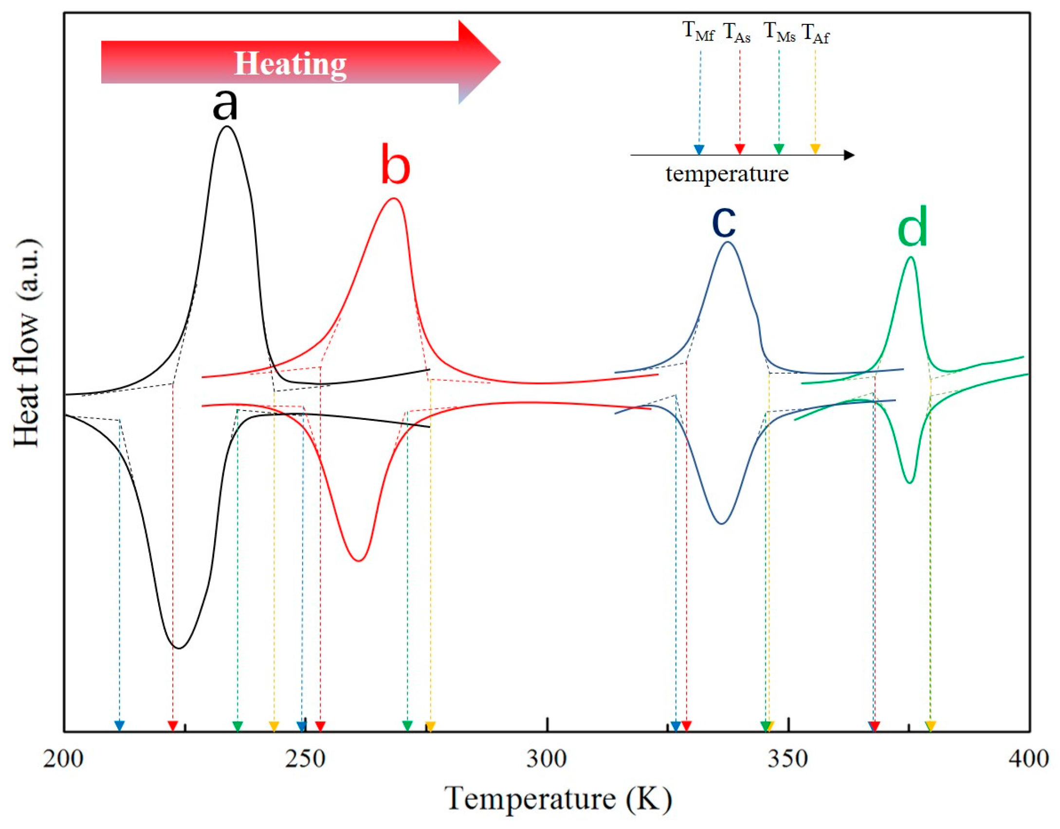
Figure 7.
Re/a of Co33Ni31Al27Fe9 alloy with furnace cooled and RS.
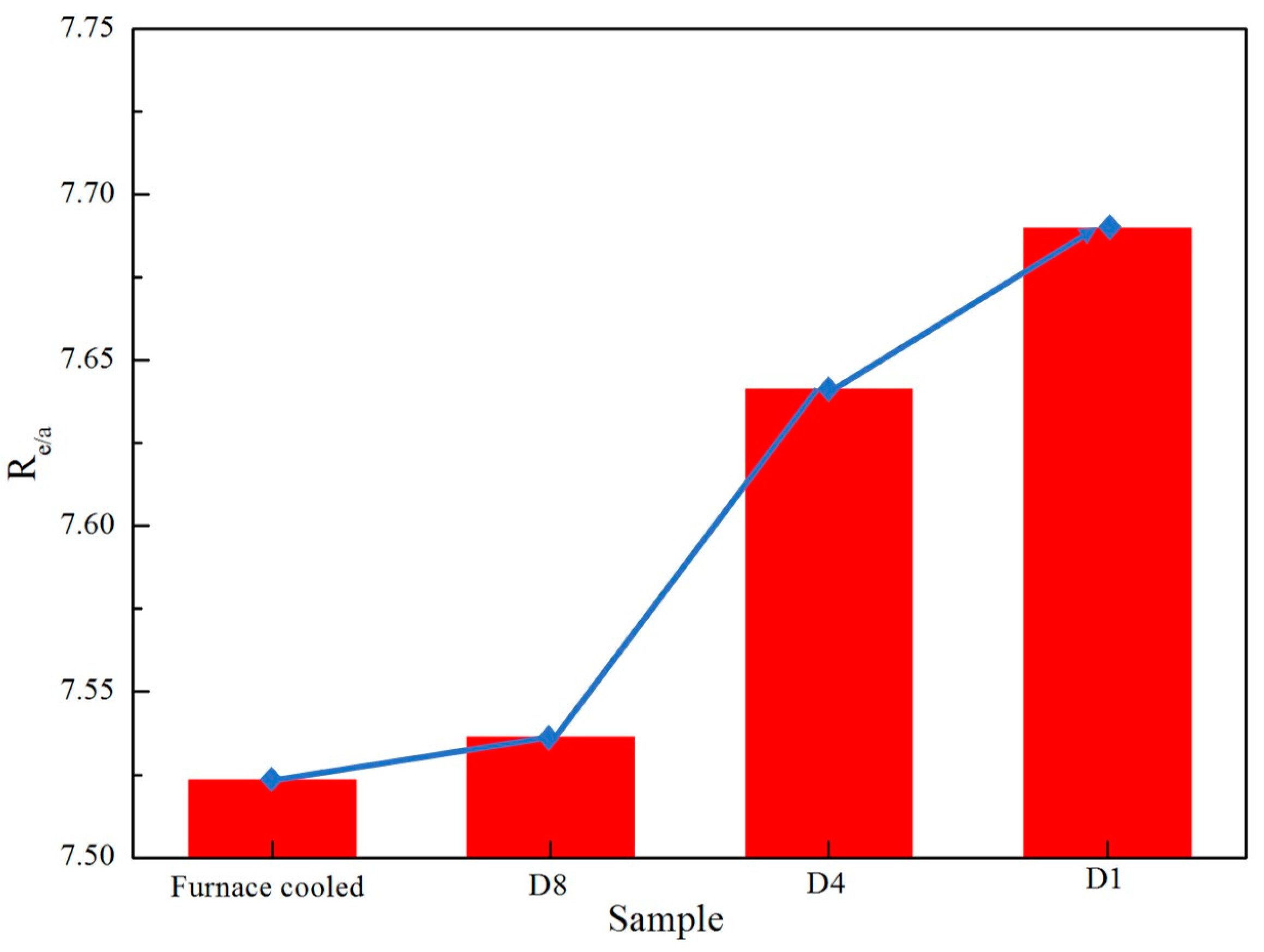
Figure 8.
Transmission electron microscopy (TEM) micrograph and corresponding selected area electron diffraction patterns (SADP) of martensite: (a) D4; (b) D1.
Figure 8.
Transmission electron microscopy (TEM) micrograph and corresponding selected area electron diffraction patterns (SADP) of martensite: (a) D4; (b) D1.

Table 1.
RC values during rapid solidification (RS) techniques.
| Alloy | Diameter (mm) | RC (K·s−1) |
|---|---|---|
| D1 | 1 | 4000 |
| D4 | 4 | 250 |
| D8 | 8 | 62.5 |
Table 2.
The difference between the desired composition and the actual composition of the sample.
| Alloy | Desired Composition (at %) | Actual Composition (at %) |
|---|---|---|
| Furnace cooled | Co33Ni31Al27Fe9 | Co33.1Ni31.5Al26.8Fe8.6 |
| D8 | Co32.8Ni31.4Al27.3Fe8.5 | |
| D4 | Co33.4Ni30.2Al28.1Fe8.3 | |
| D1 | Co32.9Ni32.4Al26.3Fe8.4 |
Table 3.
The experimental conditions and obtained phases of Co33Ni31Al27Fe9 alloy with furnace cooled and RS.
Table 3.
The experimental conditions and obtained phases of Co33Ni31Al27Fe9 alloy with furnace cooled and RS.
| Alloy | Experimental Conditions | Obtained Phases | |||
|---|---|---|---|---|---|
| Temperature (K) | Diameter (mm) | RC (K·s−1) | RC Degree | ||
| Furnace cooled | 1800 | - | <50 | Low RC value | β + γ |
| D8 | 1800 | 8 | 62.5 | Low RC value | β + γ |
| D4 | 1800 | 4 | 250 | Medium RC value | martensite + γ |
| D1 | 1800 | 1 | 4000 | High RC value | martensite + γ |
© 2017 by the authors. Licensee MDPI, Basel, Switzerland. This article is an open access article distributed under the terms and conditions of the Creative Commons Attribution (CC BY) license (http://creativecommons.org/licenses/by/4.0/).
Share and Cite
MDPI and ACS Style
Chen, H.; Ju, J.; Shuai, L.; Liu, H.; Yan, C.; Liu, Z. Structure and Martensitic Transformation in Rapidly Solidified CoNiAlFe Alloy. Metals 2017, 7, 473. https://doi.org/10.3390/met7110473
AMA Style
Chen H, Ju J, Shuai L, Liu H, Yan C, Liu Z. Structure and Martensitic Transformation in Rapidly Solidified CoNiAlFe Alloy. Metals. 2017; 7(11):473. https://doi.org/10.3390/met7110473
Chicago/Turabian StyleChen, Huiling, Jia Ju, Liguo Shuai, Huan Liu, Chen Yan, and Zhuang Liu. 2017. "Structure and Martensitic Transformation in Rapidly Solidified CoNiAlFe Alloy" Metals 7, no. 11: 473. https://doi.org/10.3390/met7110473
Note that from the first issue of 2016, this journal uses article numbers instead of page numbers. See further details here.