Article

Hexagonal Boron Nitride Impregnated Silane Composite Coating for Corrosion Resistance of Magnesium Alloys for Temporary Bioimplant Applications

by
Saad Al-Saadi
1,
Parama Chakraborty Banerjee
1,2,
M.R. Anisur
1 and
R.K. Singh Raman
1,2,*
1
Department of Mechanical and Aerospace Engineering, Monash University, Clayton VIC-3800, Australia
2
Department of Chemical Engineering, Monash University, Clayton VIC-3800, Australia
*
Author to whom correspondence should be addressed.
Metals 2017, 7(12), 518; https://doi.org/10.3390/met7120518
Submission received: 27 September 2017 / Revised: 7 November 2017 / Accepted: 7 November 2017 / Published: 23 November 2017
(This article belongs to the Special Issue Corrosion of Magnesium Alloys)

Abstract

:
Magnesium and its alloys are attractive potential materials for construction of biodegradable temporary implant devices. However, their rapid degradation in human body fluid before the desired service life is reached necessitate the application of suitable coatings. To this end, WZ21 magnesium alloy surface was modified by hexagonal boron nitride (hBN)-impregnated silane coating. The coating was chemically characterised by Raman spectroscopy. Potentiodynamic polarisation and electrochemical impedance spectroscopy (EIS) of the coated alloy in Hanks’ solution showed a five-fold improvement in the corrosion resistance of the alloy due to the composite coating. Post-corrosion analyses corroborated the electrochemical data and provided a mechanistic insight of the improvement provided by the composite coating.

1. Introduction

Potential use of magnesium (Mg) alloys as temporary implants (such as plates, screws, pins, wires, etc.) has been attracting increasing interest [1,2,3,4,5], primarily because use of such alloys could completely avoid the need for a second surgery. A second surgery is commonly required for removal of the temporary implants constructed out of traditional alloys, such as titanium alloys/stainless steels, after the implant has accomplished its function and the tissues have healed. The fundamental properties of Mg are quite suitable for their application as temporary implants. In fact, Mg is also essential to the human metabolism [6]; furthermore, the Mg2+ generated upon bio-degradation due to human body fluid has been reported to aid tissue growth and healing [7]. While the bio-degradation products of Mg are not at all toxic to the human physiology, any excess Mg2+ is harmlessly excreted through the renal system [7]. Mg and its alloys also possess the best mechanical compatibility with human bones; their density (ρ = 1.74–2.0 g·cm−3) and elastic modulus (E = 41–45 GPa) are both similar to those of human bones (ρ = 1.8–2.1 g·cm−3; E = 3–20 GPa, respectively) [7,8], which considerably decreases the risk of stress shielding [8]. WZ21 is one of the Al-free alloys that were designed for temporary implant applications [9]. Besides their suitable mechanical properties, these alloys also show good cytocompatibility, and their hydrogen generation rate is at acceptable levels for this purpose [10,11]. However, despite these attractive properties, there has been extremely limited success in the use of Mg alloys for human implants, primarily due to their unacceptably high corrosion rate in human body fluid [7,12]. It is intriguing that magnesium alloys are attractive as temporary implants primarily because they can harmlessly corrode away after they have served their purpose, thereby avoiding the need of a second surgery. However, they corrode rapidly in body fluid, which will seriously compromise the mechanical integrity of the implant, and thereby compromise the tissue-healing process. Therefore, it is essential to find a suitable coating that can provide effective protection against corrosion in presence of body fluid, at least for the first few days, when the chances of secondary inflammations are high. In selecting such coatings, two criteria are critical: (a) the coating must be biocompatible with the human body, and (b) the duration for which protection against corrosion is required will vary depending on the nature of the use of the implant. To elaborate the second point, different implants (e.g., a pin and a plate) may be required to last for different durations. Also, the same implant may be required to last for different durations, depending on the age of the patient (e.g., an implant will be required for a much shorter duration for a child than for an elderly patient).
Silane coatings have emerged as an attractive coating system, and can significantly improve the corrosion resistance of various metals and alloys, including magnesium alloys [13,14,15,16,17,18,19,20]. Additionally, silane coatings are generally biocompatible [21]. The biocompatibility test of amine silane-treated bio-glass fibres showed no negative effect on the biological response [22]. Significant increases in cell adhesion and proliferation were detected on stainless steel surfaces coated with collagen and immobilised with an amino silane [23]. As a bioactive and biocompatible binder, glycidoxypropyltrimethoxysilane was used as a precursor for synthesis of a porous gelatine-siloxane hybrids for bone tissues [24,25].
Incorporation of suitable biocompatible additives can improve the mechanical integrity, biocompatibility and corrosion resistance of silane coatings. Different biocompatible additives (i.e., Ca(NO3)2 as a source for Ca2+, hydroxyapatite, and zinc-incorporated hydroxyapatite) were used as fillers in composites, to fabricate a hybrid scaffold to enhance the biocompatibility and/or to improve the corrosion resistance of implants in simulated body fluid [24,26,27,28,29,30]. In the present research, boron nitride (BN) was impregnated into a silane coating.
Hexagonal boron nitride (BN) is a layered material consisting of two-dimensional, atomically thin hexagonal layers. Properties of BN include non-toxicity, chemical inertness, high thermal conductivity, low thermal expansion, high electrical resistance, low dielectric constant and good thermal shock resistance. Also, density (ρ = 1.9 g/cm3) and elastic moduli (E = 46.9 GPa in parallel direction and 73.8 GPa in perpendicular direction) of BN are close to the corresponding properties of human bone. BN has been used as a filler in polymeric composite to improve thermal, mechanical and other properties [31,32,33,34,35,36,37]. However, there is little reported on the incorporation of BN with silanes for formation of a composite biocompatible coating to improve corrosion resistance of Mg alloys in physiological environments. In the present study, a composite coating of hexagonal boron nitride (hBN)-impregnated silane was developed on WZ21 alloy with the aim of improving the corrosion resistance of this alloy in Hanks’ solution. The electrochemical degradation of the composite coating of BN-impregnated silane on WZ21 was investigated by electrochemical impedance spectroscopy (EIS) and potentiodynamic polarisation tests. Additionally, post-corrosion morphological and chemical characterisation were undertaken to validate the electrochemical data.

2. Materials and Methods

2.1. Composite Coating Preparation

Silane coating solution was prepared by mixing glycidoxypropyltrimethoxysilane (GPTMS, XIAMETER, Dow Corning, Auburn, MI, USA), propanol and deionised (DI) water in a ratio of 5:5:90 (V/V). The pH of the solution was adjusted to be ~4.5 by adding acetic acid. The silane mixture was stirred for 1 h, and then held still for 3 h. For impregnation of hexagonal boron nitride (hBN) into silane coating, 100 mg of hBN (procured from Sigma Aldrich, Munich, Germany; 1 µm) was dispersed in 90 mL of DI water (at pH∼4.5). Subsequently, this mixture was sonicated at room temperature for 5 h. The extended sonication at room temperature may cause exfoliation of hBN in water [38]. The exfoliated hBN was held still and subsequently, 5 ml of each of propanol and GPTMS silane was added. This mixture was stirred for 1 h at room temperature and then held still for 3 h for completion of the hydrolysis of GPTMS.

2.2. Sample Preparation and Coating Procedure

The magnesium alloy WZ21 was used in extruded form, with an average grain size of 7 µm. The nominal chemical composition (in wt %) is Zn 1%, Ca 0.25%, Mn 0.15% and Y 2% [39]. Coupons of magnesium alloy WZ21 were ground with SiC papers down to 2500 grit size, ultrasonically cleaned with acetone and ethanol (10 min for each step), rinsed with DI water, and dried using compressed air.
The coating was carried out by dipping the WZ21 coupons for 1 h either in the GPTMS solution or the hBN-impregnated silane solution (preparation of which is described in the preceding section). The coupons were then taken out of the solution, kept in air for 15 min, and dried in an oven for 1 h at 130 °C.

2.3. Electrochemical Measurements

Potentiodynamic polarisation (PDP) and electrochemical impedance spectroscopy (EIS) were carried out using a Bio-Logic VMP3 multi-channel potentiostat and a three-electrode electrochemical cell. Coupons of the bare alloy (WZ21), silane-coated alloy (S_WZ21) and hBN-impregnated silane-coated alloy (BNS_WZ21) were used as the working electrodes in separate experiments, whereas a saturated calomel electrode (SCE) was used as the reference electrode, and a platinum mesh as the counter electrode. The area of the working electrode exposed to the electrolyte was 0.785 cm2. Hanks’ solution, which simulates human body fluid, was used as electrolyte. The Hanks’ solution contained: D-Glucose (5.551 mmol/L), KCl (5.365 mmol/L), MgSO4·7H2O (0.811 mmol/L), KH2PO4 (0.441 mmol/L), Na2HPO4.2H2O (0.337 mmol/L) and NaCl (136.893 mmol/L), CaCl2 (2.163 mmol/L) and NaHCO3 (4.169 mmol/L).
Open circuit potential (OCP) was monitored for 1.5 h, i.e., until the potential attained stability, and electrochemical measurements were subsequently performed. A fluctuation of OCP within 10 mV for a period of 1000 s was considered to be a stable potential. Electrochemical impedance spectroscopy (EIS) was performed after different times of immersion in Hanks’ solution, by applying a sinusoidal potential perturbation (amplitude of 10 mV) at OCP. The impedance was measured at frequencies between 1 and 10 mHz, recording 10 points per decade of frequency using a Bio-Logic VMP3 multi-channel potentiostat (BioLogic Science Instruments, Seyssinet-Pariset, France). Impedance analysis was carried out using EC-Lab electrochemistry package for Windows, generally for frequencies between 10 kHz and 50 mHz to prevent misinterpretation of any artefacts that may be present in the high-frequency region, or the scatter in the low-frequency region. Potentiodynamic polarisation was carried out at a scan rate of 0.5 mV/s, starting at a potential of 250 mV more negative to the OCP. All the measurements were repeated at least thrice to examine reproducibility.

2.4. Surface Morphology and Coating Characterisation

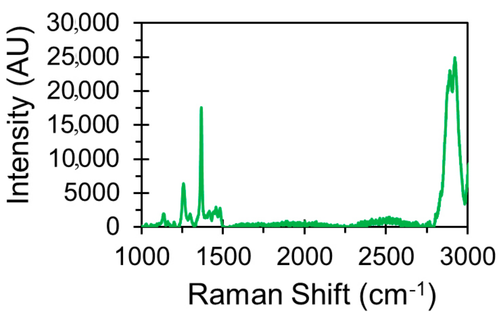
2.4.1. Raman Spectroscopy

Raman spectrum of the BNS_WZ21 was obtained using Renishaw Invia Raman spectrometer equipped with 514 nm wavelength green laser (10% of laser power) and 1 μm spot size under a 50× objective.

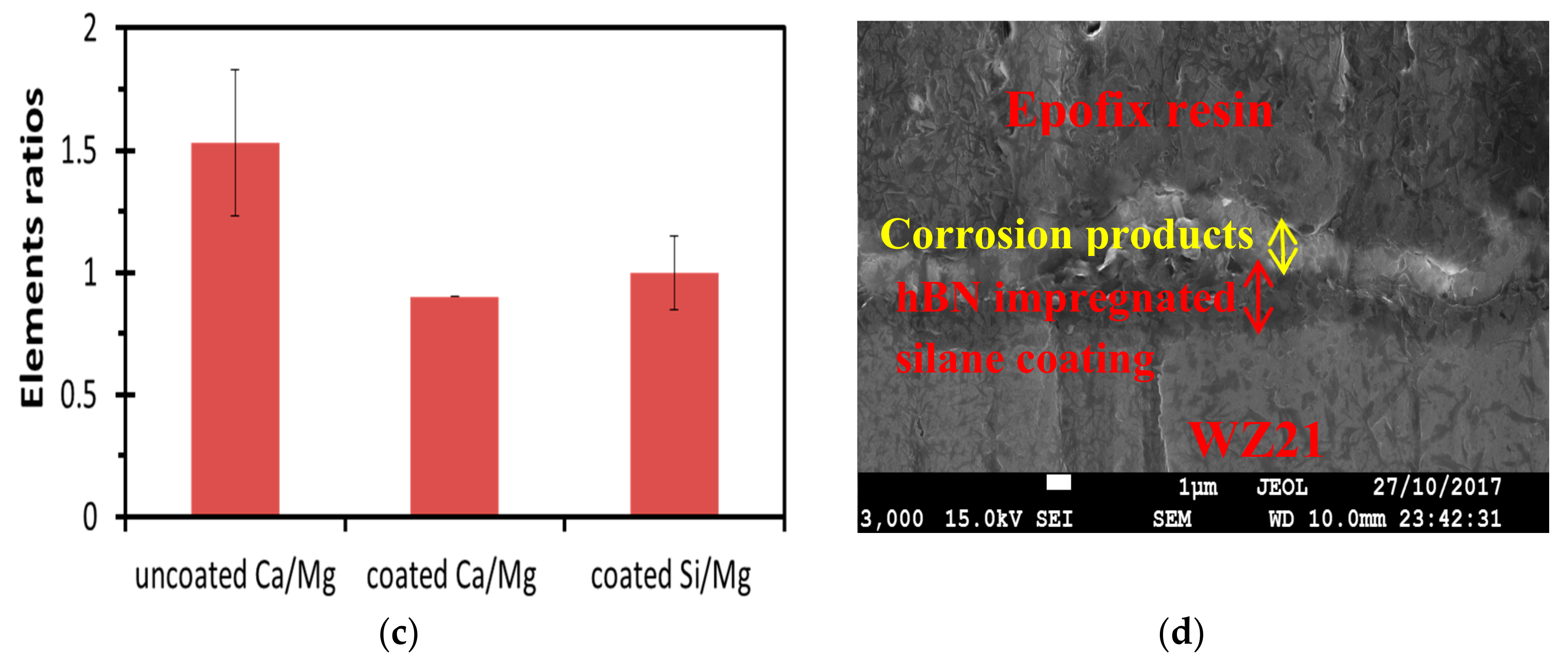
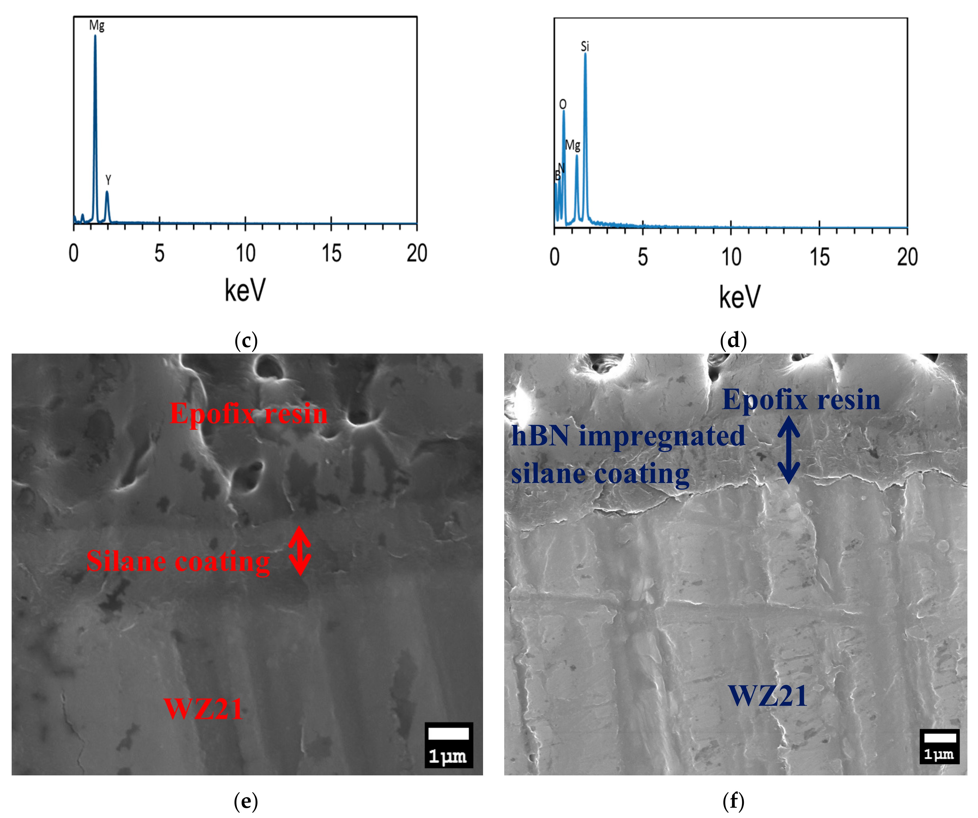
2.4.2. Scanning Electron Microscopy (SEM) and Energy Dispersive X-ray Spectroscopy (EDS)

The morphology and elemental analysis of the WZ21 and BNS_WZ21 specimens before and after exposure to Hanks’ solution were examined using JEOL JSM-7001F FEGSEM (JEOL Ltd., Tokyo, Japan) equipped with an EDS analyser at an accelerating voltage of 15 kV.

3. Results and Discussion

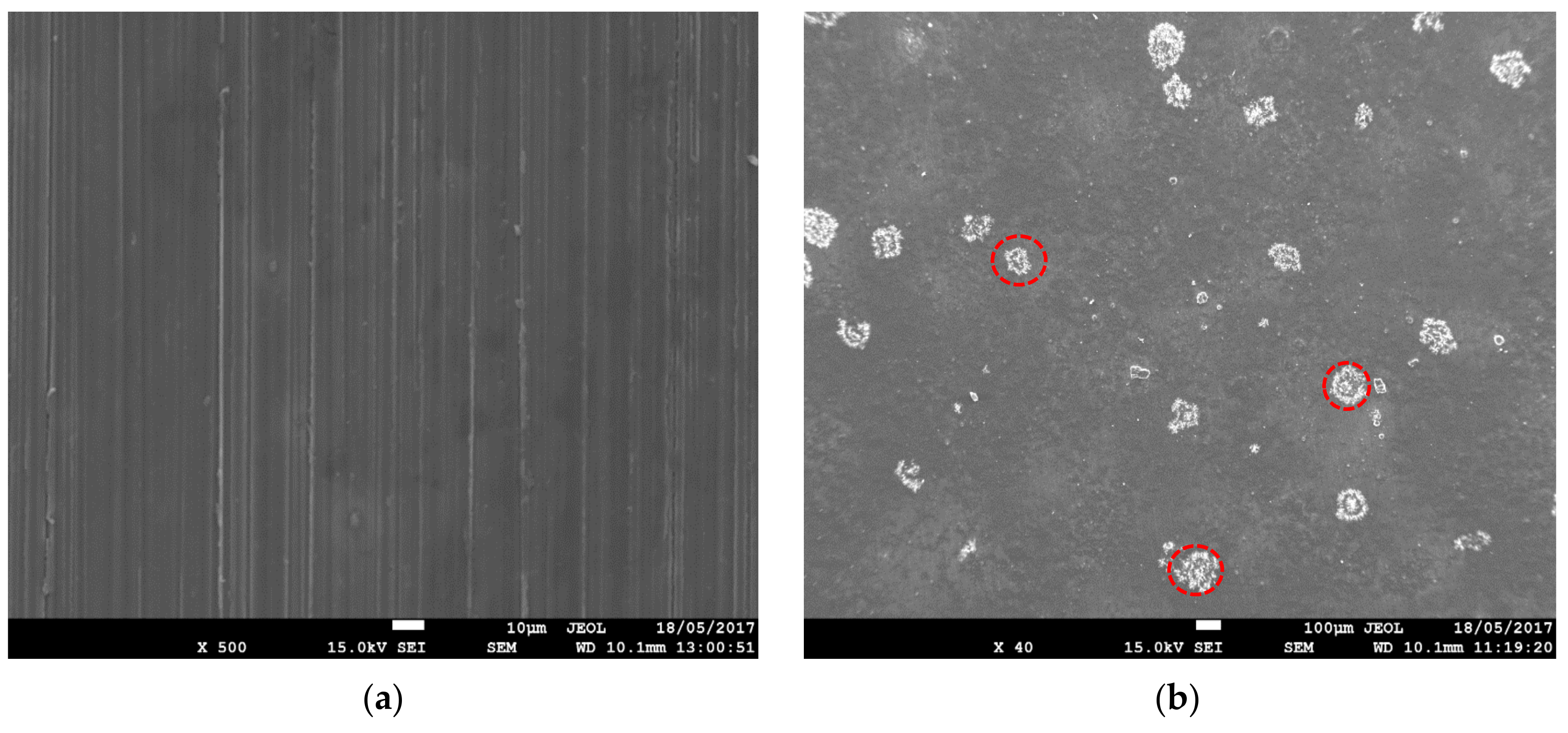
3.1. Chemical and Morphological Characterisation

The Raman spectroscopy of BNS_WZ21 in Figure 1 has the G-band peak at ∼1368 cm−1 that confirms the presence of hBN in the coating [40]. The 1256 cm−1 band is due to the symmetric ring stretch of the epoxy group in GPTMS silane [41]. The peaks at ∼3000 cm−1 and 3070 cm−1 are due to CH2 and CH stretching modes connected to epoxy groups [41]. The two peaks at 2924 and 2928 cm−1 are assigned to the hydroxyl stretching [42].
Figure 2a,b presents the SEM micrographs of the WZ21 and BNS_WZ21 specimens. Only scratch marks from the grinding process were visible on the WZ21 specimens, whereas a uniformly coated surface with cluster-like formation was observed in the case of BNS_WZ21. The average diameter of these clusters (marked with dotted line) was ~100 μm. The EDS analysis of BNS_WZ21 (Figure 2d) confirms the presence of Si, O, B and N, whereas only Mg and Yttrium (Y) peaks were prominent in case of the WZ21 specimen (Figure 2c).
Figure 2e,f reveal the cross-sectional thickness of the developed coatings (i.e., silane and the hexagonal boron nitride impregnated silane composite) on WZ21. While the average thickness of the silane coating was ~1.61 µm, the hexagonal boron nitride-impregnated silane composite coating was relatively thicker (~1.9 µm).

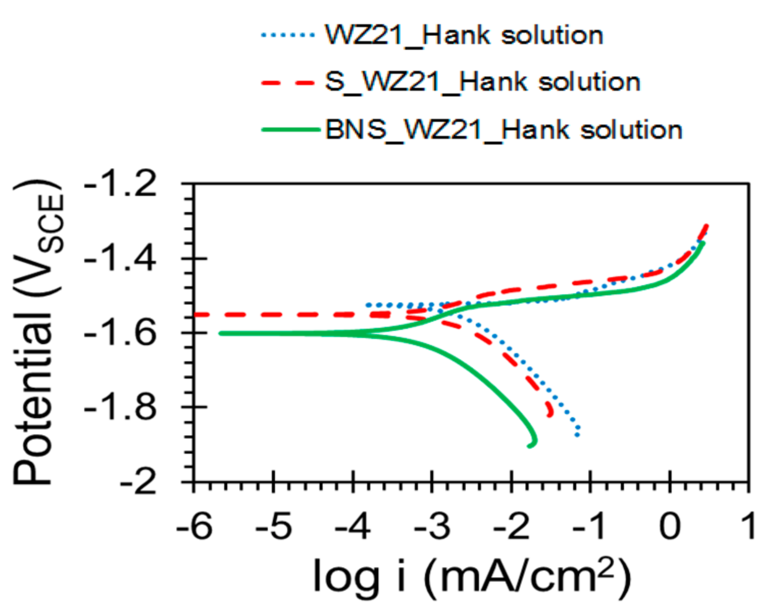
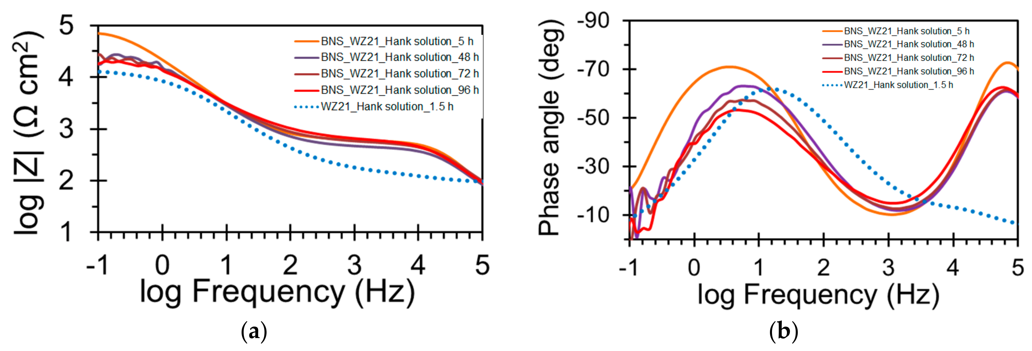
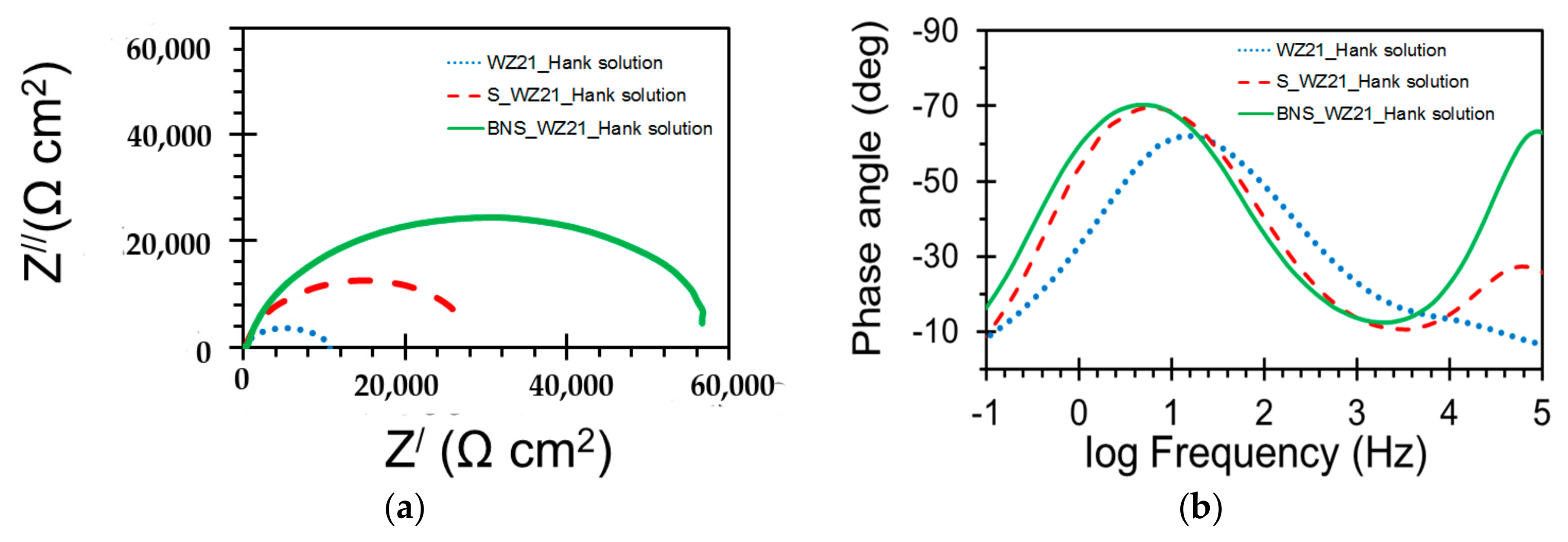
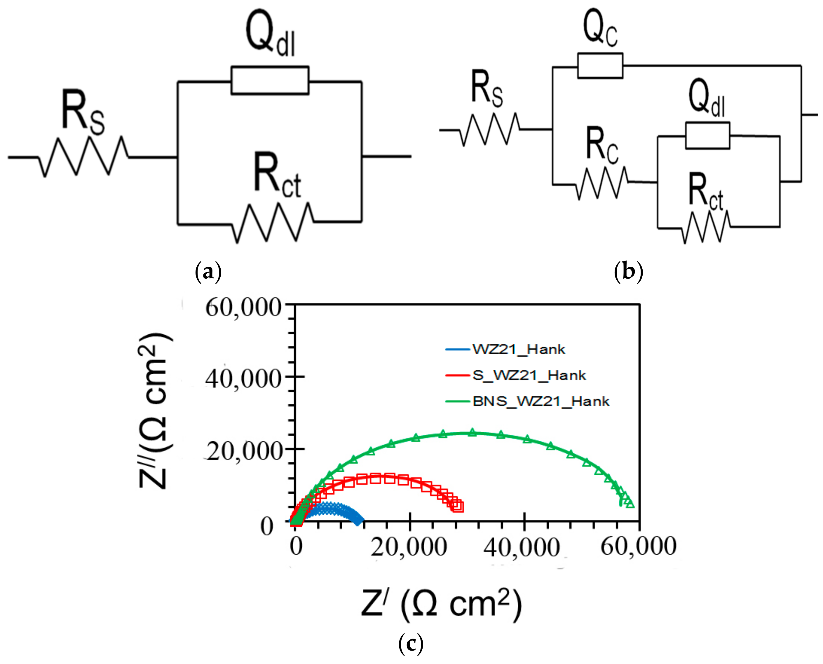
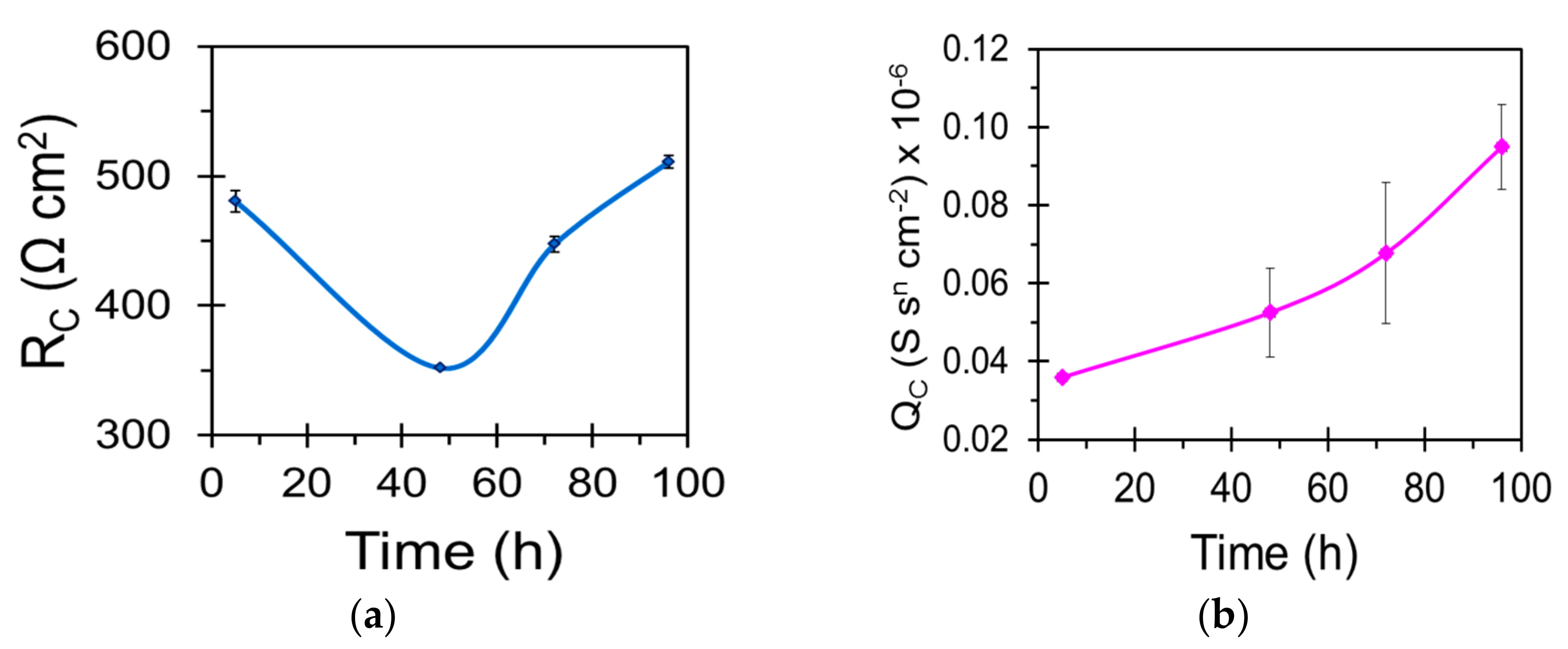
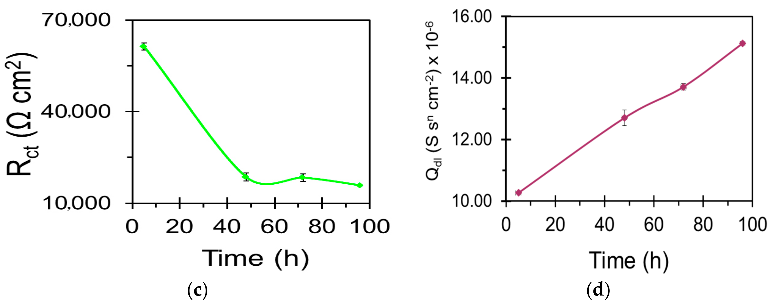
3.2. Electrochemical Characterisation

Figure 3 shows the potentiodynamic polarisation curves of WZ21, S_WZ21 and BNS_WZ21 in Hanks’ solution after pre-exposure to the same Hanks’ solution for 1.5 h. Although the corrosion potential (Ecorr) for the coated specimens (i.e., S_WZ21 and BNS_WZ21) shifted slightly to the negative direction, indicating a little increase in their susceptibility to corrosion, the corrosion current densities (icorr) of both of these specimens were lower than the icorr for the WZ21. The icorr of WZ21 was 4 times higher than that of BNS_WZ21, and twice that of the S_WZ21. These results suggest that the hBN-impregnated silane coating significantly improved the corrosion resistance of WZ21 alloy in Hanks’ solution by retarding the cathodic reaction. Such behaviour could be attributed to the formation of a protective layer on the cathodic active sites on WZ21 surface. The Ecorr and the icorr data as generated from the potentiodynamic polarisation tests are presented in Table 1.
The EIS data for the WZ21, S_WZ21 and BNS_WZ21 in Hanks’ solution with pre-exposure to the same Hanks’ solution for 1.5 h are shown in Nyquist and Bode phase plots in Figure 4a,b. Consistent with polarisation results (Figure 3), the silane coating (S_WZ21) improved the corrosion resistance of the alloy by 2.5 times, as suggested by the increase in impedance at a lowest frequency of 11 kΩ·cm2 for the bare alloy to 27 kΩ·cm2 for the silane-coated alloy. However, the impregnation of the silane coating with hBN (BNS_WZ21) further improved the corrosion resistance (by > 5 times), as suggested by the impedance (57 kΩ·cm2).
For S_WZ21 and BNS_WZ21, two distinct time constants can be observed in Figure 4b. The high-frequency regime time constant is generally attributed to the electrochemical response at the coatings/electrolyte interface [19,20,43,44,45,46,47,48,49], whereas the time constant in the low-frequency regime is commonly attributed to the electrochemical response at the metal/electrolyte interface [19,20,45,46,47,48,49,50,51]. The high-frequency regime time constant is much prominent in the case of BNS_WZ21. The WZ21 showed a single time constant, i.e., at low frequencies.
A classic Randles circuit (Figure 5a) could explain the electrode kinetics of the WZ21 exposed to the Hanks’ solution, where Rs represents the electrolyte resistance. Rct represents the charge transfer resistance and Qdl is the constant phase element of the alloy/electrolyte interface. However, an electrical equivalent circuit (EEC) with an additional time constant (RCQC) was required to explain the kinetics of S_WZ21 and BNS_WZ21 (Figure 5b) during immersion in Hank’s solution. The simulated impedance data were in good agreement with the experimental data, as shown in Figure 5c. In the EECs, in Figure 5a,b, a constant phase element (Q) is used instead of a capacitor (C) in order to account for the surface reactivity, heterogeneity, roughness, electrode porosity and current and potential distributions associated with the electrode geometry [43]. Table 2 presents the values of EIS parameters of the WZ21, S_WZ21 and BNS_WZ21 after 1.5 h of immersion in Hanks’ solution. Rc was considerably higher for BNS_WZ21 than that for S_WZ21, whereas the Qc was higher for S_WZ21 alone, which indicates the higher pore resistance and lower number of conductive pathways through the BNS_WZ21. Additionally, the BNS_WZ21 shows considerably higher Rct (~59 kΩ·cm2) than the WZ21 (~11 kΩ cm2) and S_WZ21 (~30 kΩ·cm2), which further supports that the addition of hBN decreases the corrosion rate of WZ21 alloy. Further, the lowest value of Qdl for BNS_WZ21 indicates a lesser area at the coating/metal interface getting in contact with the electrolyte than other samples.
In order to investigate the durability of the barrier properties of the hBN-impregnated silane coating, EIS was performed on the BNS_WZ21 alloy after different durations of immersion in Hanks’ solution. Figure 6a compares the Bode plots of the WZ21 at 1.5 h of immersion with the BNS_WZ21 after different durations of immersion (i.e., 5–96 h) in Hanks’ solution. After 5 h of immersion, the corrosion resistance of the BNS_WZ21 specimen (~57 kΩ·cm2) was nearly 5 times higher than that of the WZ21 specimen (~11 kΩ·cm2). However, the corrosion resistance of the BNS_WZ21 gradually decreased with increasing immersion time. Nevertheless, the corrosion resistance of the BNS_WZ21 even after 96 h (~16 kΩ·cm2) was 1.5 times higher than that of the WZ21 specimen (~11 kΩ·cm2) immersed just for 1.5 h. Figure 6b shows the phase angle plots of the BNS_WZ21 after different durations of immersion in Hanks’ solution. Small changes in the magnitude, as well as the nature, of both the low- and high-frequency time constants with increasing immersion time suggest a slow degradation rate for the coating.
The impedance data of the BNS_WZ21 immersed in Hanks’ solution for different durations (5–96 h) were fitted with the simulation data generated using the equivalent electrical circuit (ECC) in Figure 5b. Evolution of the electrochemical parameters at the coating/electrolyte and the metal/electrolyte interfaces during 96 h immersion are shown in Figure 7. The coating resistance (Rc) gradually decreased in the first 50 h and then continuously increased. The decrease in pore resistance during the first 50 h suggests an increase in the conductive pathways in the coating [19,20], which is supported by the increase in the constant phase element (Qc) that results from increased activity at the coating/electrolyte interface (Figure 7b). The initial decrease in pore resistance and the corresponding increase in number of conductive pathways through the coating explain the decrease in charge transfer resistance (Rct) at the metal/electrolyte interface (Figure 7c), as well as the increase in the double layer capacitance (Qdl). This is consistent with the deterioration in silane coating with increasing duration of immersion in the corrosive solution, as reported in the literature [19,20].

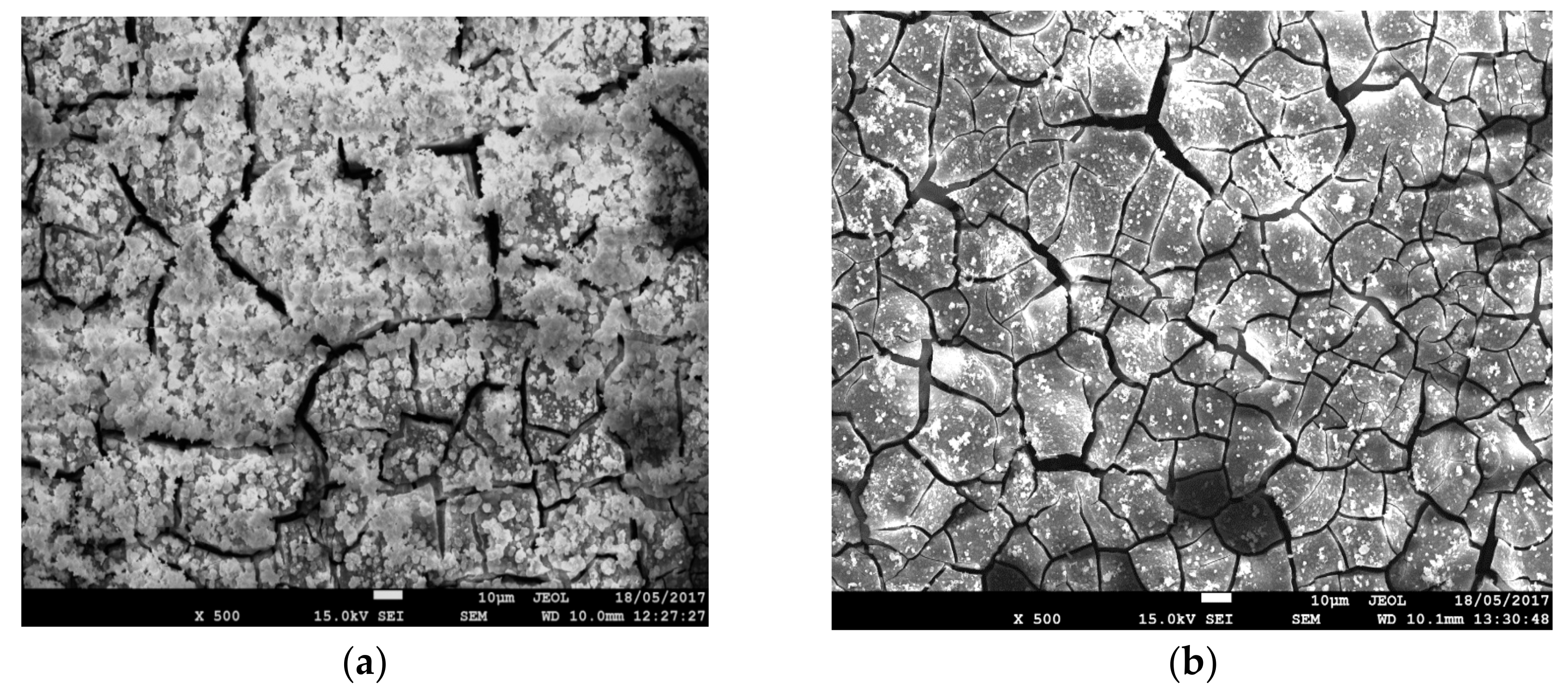
3.3. Post-Corrosion Morphology of Bare WZ21 and BNS_WZ21

Figure 8 shows the post-corrosion morphologies and surface chemical analysis of the WZ21 and BNS_WZ21 specimens pre-exposed to Hanks’ solution for 96 h. The entire surface of WZ21 was covered with thick corrosion products (Figure 8a), whereas considerably less amounts of corrosion products could be observed on the BNS_WZ21 (Figure 8b). The cracks in both samples resulted from their exposure to the high vacuum in the SEM chamber, which is well known to rapidly dehydrate the surface films, thereby causing cracks.
It is well known that when a magnesium alloy is exposed to Hanks’ solution, calcium phosphate deposition occurs at the expense of magnesium oxide formation [52]. The relative quantities of Ca and Si to Mg on the WZ21 and the BNS_WZ21 specimens after exposure to Hanks’ solution were characterised by EDS analysis. As expected, the Ca-to-Mg ratio of the deposited corrosion products for WZ21 was higher than that for BNS_WZ21 (Figure 8c). Additionally, the Si-to-Mg ratio was prominent in the case of BNS_WZ21 (Figure 8c), suggesting that the silane-containing composite coating was present on the alloy even after 96 h exposure to simulated human body fluid (Hanks’ solution). Figure 8d shows the cross-section of the hexagonal boron nitride-impregnated silane composite coating developed on WZ21 alloy after exposure to Hanks’ solution for 96 h. Despite scattered corrosion products with average thickness (~1.16 µm) being visible on the top of the developed composite coating layer, no corrosion products or delaminated coating were noticed at the coating/metal interface. The average thickness of the composite coating after 96h of exposure to Hanks’ solution was found to be ~1.793 µm, which is smaller than the average thickness of the intact composite coating (~1.9 µm) prior to exposure to Hanks’ solution.

4. Conclusions

Hexagonal boron nitride (hBN) was impregnated successfully into silane for the development of a two-dimensional biocompatible composite coating on WZ21 Mg alloy, which significantly improved the corrosion resistance and durability of the alloy in a physiological environment. Potentiodynamic polarisation and electrochemical impedance spectroscopy (EIS) analyses confirmed nearly five-fold improvement in corrosion resistance of the Mg alloy (WZ21) in simulated human body fluid during the first hours of immersion, due to the coating. Post-corrosion morphologies show the formation of a thick corrosion product on the WZ21 surface, but considerably less corrosion products on the BNS_WZ21 surface even after 96 h immersion in Hanks’ solution.

Author Contributions

Saad Al-Saadi did the synthesis of saline and hexagonal boron nitride (hBN)-impregnated silane coatings. He carried out the Mg alloy sample preparation, coating and electrochemical tests at the corrosion laboratory in the Chemical Engineering Department, Monash University. M.R. Anisur carried out the characterisation of the coated Mg alloy by Raman spectroscopy. Scanning electron microscopy was carried out at the Monash Centre for Electron Microscopy by Saad Al-Saadi. Al-Saadi prepared the manuscript under the guidance of R.K. Singh Raman and Parama Chakraborty Banerjee.

Conflicts of Interest

The authors declare no conflict of interest.

References

  1. Zberg, B.; Uggowitzer, P.J.; Löffler, J.F. MgZnCa glasses without clinically observable hydrogen evolution for biodegradable implants. Nat. Mater. 2009, 8, 887–891. [Google Scholar] [CrossRef] [PubMed]
  2. Ma, E.; Xu, J. Biodegradable Alloys: The glass window of opportunities. Nat. Mater. 2009, 8, 855–857. [Google Scholar] [CrossRef] [PubMed]
  3. Kannan, M.B.; Raman, R.K.S. In vitro degradation and mechanical integrity of calcium-containing magnesium alloys in modified-simulated body fluid. Biomaterials 2008, 29, 2306–2314. [Google Scholar] [CrossRef] [PubMed]
  4. Witte, F.; Kaese, V.; Haferkamp, H.; Switzer, E.; Meyer-Lindenberg, A.; Wirth, C.J.; Windhagen, H. In vivo corrosion of four magnesium alloys and the associated bone response. Biomaterials 2005, 26, 3557–3563. [Google Scholar] [CrossRef] [PubMed]
  5. Witte, F.; Fischer, J.; Nellesen, J.; Horst-Artur, C.; Kaese, V.; Pisch, A.; Beckmann, F.; Windhagen, H. In vitro and in vivo corrosion measurements of magnesium alloys. Biomaterials 2006, 27, 1013–1018. [Google Scholar] [CrossRef] [PubMed]
  6. Manivasagam, G.; Suwas, S. Biodegradable Mg and Mg based alloys for biomedical implants. Mater. Sci. Technol. 2014, 30, 515–520. [Google Scholar] [CrossRef]
  7. Staiger, M.P.; Pietak, A.M.; Huadmai, J.; Dias, G. Magnesium and its alloys as orthopedic biomaterials: A review. Biomaterials 2006, 27, 1728–1734. [Google Scholar] [CrossRef] [PubMed]
  8. Seal, C.K.; Vince, K.; Hodgson, M.A. Biodegradable surgical implants based on magnesium alloys—A review of current research. In Proceedings of the IOP Conference Series: Materials Science and Engineering, Strasbourg, France, 8–12 June 2009; IOP Publishing: Bristol, UK, 2009. [Google Scholar]
  9. Hänzi, A.C.; Gerber, I.; Schinhammer, M.; Löffler, J.F.; Uggowitzer, P.J. On the in vitro and in vivo degradation performance and biological response of new biodegradable Mg-Y-Zn alloys. Acta Biomater. 2010, 6, 1824–1833. [Google Scholar] [CrossRef] [PubMed]
  10. Kirkland, N.T.; Williams, G.; Birbilis, N. Observations of the galvanostatic dissolution of pure magnesium. Corros. Sci. 2012, 65, 5–9. [Google Scholar] [CrossRef]
  11. Kraus, T.; Fischerauer, S.F.; Hänzi, A.C.; Uggowitzer, P.J.; Löffler, J.F.; Weinberg, A.M. Magnesium alloys for temporary implants in osteosynthesis: In vivo studies of their degradation and interaction with bone. Acta Biomater. 2012, 8, 1230–1238. [Google Scholar] [CrossRef] [PubMed]
  12. Ghoneim, A.A.; Fekry, A.M.; Ameer, M.A. Electrochemical behavior of magnesium alloys as biodegradable materials in Hank’s solution. Electrochim. Acta 2010, 55, 6028–6035. [Google Scholar] [CrossRef]
  13. Zucchi, F.; Grassi, V.; Frignani, A.; Monticelli, C.; Trabanelli, G. Influence of a silane treatment on the corrosion resistance of a WE43 magnesium alloy. Surf. Coat. Technol. 2006, 200, 4136–4143. [Google Scholar] [CrossRef]
  14. Zomorodian, A.; Brusciotti, F.; Fernandes, A.; Carmezim, M.J.; Silva, T.M.; Fernandes, J.C.S.; Montemor, M.F. Anti-corrosion performance of a new silane coating for corrosion protection of AZ31 magnesium alloy in Hank’s solution. Surf. Coat. Technol. 2012, 206, 4368–4375. [Google Scholar] [CrossRef]
  15. Lamaka, S.V.; Montemor, M.F.; Galio, A.F.; Zheludkevich, M.L.; Trindade, C.; Dick, L.F.; Ferreira, M.G.S. Novel hybrid sol-gel coatings for corrosion protection of AZ31B magnesium alloy. Electrochim. Acta 2008, 53, 4773–4783. [Google Scholar] [CrossRef]
  16. Hu, J.; Li, Q.; Zhong, X.K.; Li, L.Q.; Zhang, L. Organic coatings silane-based for AZ91D magnesium alloy. Thin Solid Films 2010, 519, 1361–1366. [Google Scholar] [CrossRef]
  17. Zucchi, F.; Frignani, A.; Grassi, V.; Trabanelli, G. Organo-silane coatings for AZ31 magnesium alloy corrosion protection. Mater. Chem. Phys. 2008, 110, 263–268. [Google Scholar] [CrossRef]
  18. Ivanou, D.K.; Starykevich, M.; Lisenkov, A.D.; Zheludkevich, M.L.; Xue, H.B.; Lamaka, S.V.; Ferreira, M.G.S. Plasma anodized ZE41 magnesium alloy sealed with hybrid epoxy-silane coating. Corros. Sci. 2013, 73, 300–308. [Google Scholar] [CrossRef]
  19. Chakraborty Banerjee, P.; Singh Raman, R.K. Electrochemical impedance spectroscopic investigation of the role of alkaline pre-treatment in corrosion resistance of a silane coating on magnesium alloy, ZE41. Electrochim. Acta 2011, 56, 3790–3798. [Google Scholar] [CrossRef]
  20. Al-Saadi, S.; Banerjee, P.C.; Raman, R.K.S. Corrosion of bare and silane-coated mild steel in chloride medium with and without sulphate reducing bacteria. Prog. Org. Coat. 2017, 111, 231–239. [Google Scholar] [CrossRef]
  21. Ravenscroft-Chang, M.S.; Stohlman, J.M.; Molnar, P.; Natarajan, A.; Teliska, M.; Stancescu, M.; Krauthamer, V.; Hickman, J.J. Altered calcium dynamics in cardiac cells grown on silane-modified surfaces. Biomaterials 2010, 31, 602–607. [Google Scholar] [CrossRef] [PubMed]
  22. Jiang, G.; Evans, M.E.; Jones, I.A.; Rudd, C.D.; Scotchford, C.A.; Walker, G.S. Preparation of poly(ε-caprolactone)/continuous bioglass fibre composite using monomer transfer moulding for bone implant. Biomaterials 2005, 26, 2281–2288. [Google Scholar] [CrossRef] [PubMed]
  23. Müller, R.; Abke, J.; Schnell, E.; Macionczyk, F.; Gbureck, U.; Mehrl, R.; Ruszczak, Z.; Kujat, R.; Englert, C.; Nerlich, M.; et al. Surface engineering of stainless steel materials by covalent collagen immobilization to improve implant biocompatibility. Biomaterials 2005, 26, 6962–6972. [Google Scholar] [CrossRef] [PubMed]
  24. Ren, L.; Tsuru, K.; Hayakawa, S.; Osaka, A. Novel approach to fabricate porous gelatin–siloxane hybrids for bone tissue engineering. Biomaterials 2002, 23, 4765–4773. [Google Scholar] [CrossRef]
  25. Ren, L.; Tsuru, K.; Hayakawa, S.; Osaka, A. Synthesis and Characterization of Gelatin-Siloxane Hybrids Derived through Sol-Gel Procedure. J. Sol-Gel Sci. Technol. 2001, 21, 115–121. [Google Scholar] [CrossRef]
  26. Ren, L.; Tsuru, K.; Hayakawa, S.; Osaka, A. Sol–gel preparation and in vitro deposition of apatite on porous gelatin–siloxane hybrids. J. Non-Cryst. Solids 2001, 285, 116–122. [Google Scholar] [CrossRef]
  27. Dupraz, A.M.P.; Meer, S.A.T.; Wijn, J.R.D.; Goedemoed, J.H. Biocompatibility screening of silane-treated hydroxyapatite powders, for use as filler in resorbable composites. J. Mater. Sci. Mater. Med. 1996, 7, 731–738. [Google Scholar] [CrossRef]
  28. Nakkiew, W. Optimal Conditions of Electrostatic Spray Deposition (ESD) for Composite Biomaterials Coating for Biomedical Applications. Adv. Mater. Res. 2013, 748, 175–179. [Google Scholar] [CrossRef]
  29. Chetibi, L.; Hamana, D.; Achour, S. Growth and characterization of hydroxyapatite nanorice on TiO2 nanofibers. Mater. Chem. Phys. 2014, 144, 301–309. [Google Scholar] [CrossRef]
  30. Sutha, S.; Karunakaran, G.; Rajendran, V. Enhancement of antimicrobial and long-term biostability of the zinc-incorporated hydroxyapatite coated 316L stainless steel implant for biomedical application. Ceram. Int. 2013, 39, 5205–5212. [Google Scholar] [CrossRef]
  31. Lee, G.-W.; Park, M.; Kim, J.; Lee, J.I.; Yoon, H.G. Enhanced thermal conductivity of polymer composites filled with hybrid filler. Compos. Part A Appl. Sci. Manuf. 2006, 37, 727–734. [Google Scholar]
  32. Xie, B.H.; Huang, X.; Zhang, G.J. High thermal conductive polyvinyl alcohol composites with hexagonal boron nitride microplatelets as fillers. Compos. Sci. Technol. 2013, 85, 98–103. [Google Scholar] [CrossRef]
  33. Zhi, C.; Bando, Y.; Tang, C.C.; Kuwahara, H.; Golberg, D. Large-Scale Fabrication of Boron Nitride Nanosheets and Their Utilization in Polymeric Composites with Improved Thermal and Mechanical Properties. Adv. Mater. 2009, 21, 2889–2893. [Google Scholar] [CrossRef]
  34. Harada, M.; Hamaura, N.; Ochi, M.; Agari, Y. Thermal conductivity of liquid crystalline epoxy/BN filler composites having ordered network structure. Compos. Part B Eng. 2013, 55, 306–313. [Google Scholar] [CrossRef]
  35. TabkhPaz, M.; Shajari, S.; Mahmoodi, M.; Park, D.Y.; Suresh, H.; Park, S.S. Thermal conductivity of carbon nanotube and hexagonal boron nitride polymer composites. Compos. Part B Eng. 2016, 100, 19–30. [Google Scholar] [CrossRef]
  36. Pan, C.; Kou, K.; Jia, Q.; Wu, G.L.; Ji, T.Z. Improved thermal conductivity and dielectric properties of hBN/PTFE composites via surface treatment by silane coupling agent. Compos. Part B Eng. 2017, 111, 83–90. [Google Scholar] [CrossRef]
  37. Jeong, S.H.; Song, J.B.; Kim, K.L.; Choi, Y.H.; Lee, H. Enhanced thermal properties of epoxy composite containing cubic and hexagonal boron nitride fillers for superconducting magnet applications. Compos. Part B Eng. 2016, 107, 22–28. [Google Scholar] [CrossRef]
  38. Husain, E.; Narayanan, T.N.; Taha-Tijerina, J.J.; Vinod, S.; Vajtai, R.; Ajayan, P.M. Marine Corrosion Protective Coatings of Hexagonal Boron Nitride Thin Films on Stainless Steel. ACS Appl. Mater. Interfaces 2013, 5, 4129–4135. [Google Scholar] [CrossRef] [PubMed]
  39. Choudhary, L.; Singh, R.R.K.; Hofstetter, J.; Uggowitzer, P.J. In-vitro characterization of stress corrosion cracking of aluminium-free magnesium alloys for temporary bio-implant applications. Mater. Sci. Eng. C 2014, 42, 629–636. [Google Scholar] [CrossRef] [PubMed]
  40. Geick, R.; Perry, C.H.; Rupprecht, G. Normal Modes in Hexagonal Boron Nitride. Phys. Rev. 1966, 146, 543–547. [Google Scholar] [CrossRef]
  41. Šapić, I.M.; Bistričić, L.; Volovšek, V.; Dananić, V. Vibrational Analysis of 3-Glycidoxypropyltrimethoxysilane Polymer. Macromol. Symp. 2014, 339, 122–129. [Google Scholar] [CrossRef]
  42. Ma, P.C.; Kim, J.K.; Tang, B.Z. Functionalization of carbon nanotubes using a silane coupling agent. Carbon 2006, 44, 3232–3238. [Google Scholar] [CrossRef]
  43. Macdonald, J.R. Impedance Spectroscopy Theory, Experiment, and Applications, 2nd ed.; Wiley: Hoboken, NJ, USA, 2005. [Google Scholar]
  44. Banerjee, P.; Woo, R.P.; Grayson, S.M.; Majumder, A.; Raman, R.K.S. Influence of Zeolite Coating on the Corrosion Resistance of AZ91D Magnesium Alloy. Materials 2014, 7, 6092–7004. [Google Scholar] [CrossRef] [PubMed]
  45. Singh Raman, R.K.; Banerjee, P.C.; Lobo, D.E.; Gullapalli, H.; Sumandasa, M.; Choudhary, L.; Tkacz, R.; Ajayan, P.M.; Majumder, M. Protecting copper from electrochemical degradation by graphene coating. Carbon 2012, 50, 4040–4045. [Google Scholar] [CrossRef]
  46. Zhu, D.; Ooij, W.J. Corrosion protection of AA 2024-T3 by bis-[3-(triethoxysilyl)propyl]tetrasulfide in sodium chloride solution. Corros. Sci. 2003, 45, 2177–2197. [Google Scholar] [CrossRef]
  47. Cabral, A.M.; Duarte, R.G.; Montemor, M.F.; Ferreira, M.G.S. A comparative study on the corrosion resistance of AA2024-T3 substrates pre-treated with different silane solutions. Prog. Org. Coat. 2005, 54, 322–331. [Google Scholar] [CrossRef]
  48. Montemor, M.F.; Ferreira, M.G.S. Electrochemical study of modified bis-[triethoxysilylpropyl] tetrasulfide silane films applied on the AZ31 Mg alloy. Electrochim. Acta 2007, 52, 7486–7495. [Google Scholar] [CrossRef]
  49. Wang, H.; Akid, R. A room temperature cured sol–gel anticorrosion pre-treatment for Al 2024-T3 alloys. Corros. Sci. 2007, 49, 4491–4503. [Google Scholar] [CrossRef]
  50. Banerjee, P.C.; Singh, R.; Durandet, Y.; McAdam, G. Electrochemical investigation of the influence of laser surface melting on the microstructure and corrosion behaviour of ZE41 magnesium alloy–An EIS based study. Corros. Sci. 2011, 53, 1505–1514. [Google Scholar] [CrossRef]
  51. Banerjee, P.C.; Singh, R.R.K.; Durandet, Y.; McAdam, G. Influence of Laser Surface Melting on the Microstructure and Corrosion Behaviour of ZE41 Magnesium Alloy. Mater. Sci. Forum 2009, 618–619, 263–268. [Google Scholar] [CrossRef]
  52. Harandi, S.E.; Banerjee, P.C.; Easton, C.D.; Raman, R.K.S. Influence of bovine serum albumin in Hanks’ solution on the corrosion and stress corrosion cracking of a magnesium alloy. Mater Sci. Eng. C 2017, 80, 335–345. [Google Scholar] [CrossRef] [PubMed]
Figure 1. Raman spectroscopy of the hBN impregnated silane-coated WZ21 (BNS_WZ21) specimen.
Metals 07 00518 g001
Figure 2. (a,b) Scanning Electron Microscopy (SEM) images of WZ21 and BNS_WZ21 (cluster-like formation of hBN is marked with red circles), (c,d) Energy Dispersive X-ray (EDS) of bare and BNS_WZ21, (e,f) cross-sectional thickness of silane- and hexagonal boron nitride-impregnated silane composite coatings.
Metals 07 00518 g002aMetals 07 00518 g002b
Figure 3. Potentidynamic polarisation plots of WZ21, S_WZ21 and BNS_WZ21 pre-immersed for 1.5 h in Hank’s solution.
Metals 07 00518 g003
Figure 4. (a) Nyquist and (b) phase plots for WZ21, S_WZ21 and BNS_WZ21 pre-immersed for 1.5 h in Hank solution.
Metals 07 00518 g004
Figure 5. (a) Electrical equivalent circuit (EEC) that fits data for WZ21, and (b) EEC that fits data for S_WZ21 and BNS_WZ21, pre-immersed for 1.5 h in Hanks’ solution. (c) The agreement between the experimental and fitted data of EIS measurements (lines represent the experimental data and symbols represent the fitted data).
Metals 07 00518 g005
Figure 6. (a) Bode and (b) phase plots of the WZ21 pre-immersed for 1.5 h in Hank’s solution and the BNS_WZ21 pre-immersed up to 96 h.
Metals 07 00518 g006
Figure 7. Evolution of (a,b) the coating/electrolyte and (c,d) the metal/electrolyte interfaces of the hBN-impregnated silane-coated WZ21 (BNS_WZ21) pre-immersed up to 96 h.
Metals 07 00518 g007aMetals 07 00518 g007b
Figure 8. SEM micrographs and chemical element ratios of EDS of WZ21 and BNS_WZ21 specimens after exposure to Hanks’ solution: (a,b) SEM images of WZ21 and BNS_WZ21; (c) The ratios of chemical elements obtained by EDS analysis after exposure to Hanks’ solution; (d) The cross-sectional thickness of the hexagonal boron nitride-impregnated silane composite coating on WZ21 alloy pre-exposed to Hank’s solution.
Metals 07 00518 g008aMetals 07 00518 g008b
Table 1. Corrosion potential (Ecorr) and corrosion current density (icorr) data for WZ21, S_WZ21 and BNS_WZ21 coupons exposed to Hanks’ solution for 1.5 h.
SampleEcorr (VSCE)icorr (µA/cm2)
WZ21−1.525 (±0.0083)1.217 (±0.269)
S_WZ21−1.546 (±0.009)0.538 (±0.059)
BNS_WZ21−1.594 (±0.007)0.292 (±0.006)
Table 2. Electrochemical impedance spectroscopy (EIS) results for the corrosion of WZ21, S_WZ21 and BNS_WZ21 coupons exposed to Hanks’ solution for 1.5 h.
SampleQc (S·sn·cm−2)ncRc (Ω·cm2)Qdl (S sn cm−2)ndlRct (Ω·cm2)
WZ21---2.639 × 10−50.711,048
S_WZ212.164 × 10−60.62131.106 × 10−50.929,736
BNS_WZ215.169 × 10−80.94038.735 × 10−60.959,364

