Experimental and Numerical Studies of Sheet Metal Forming with Damage Using Gas Detonation Process

 ,
, 

Abstract
:
1. Introduction
2. Methods and Setup
2.1. Experimental Setup
2.2. Numerical Modeling
3. Results and Discussion
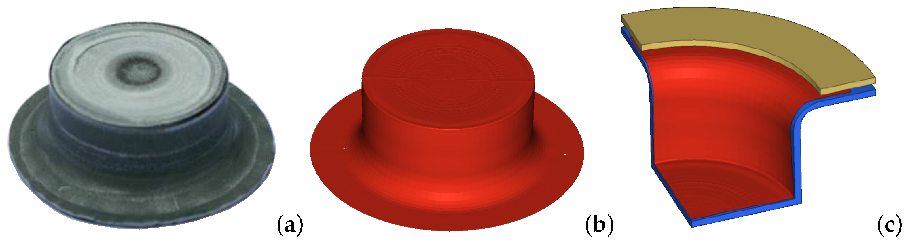
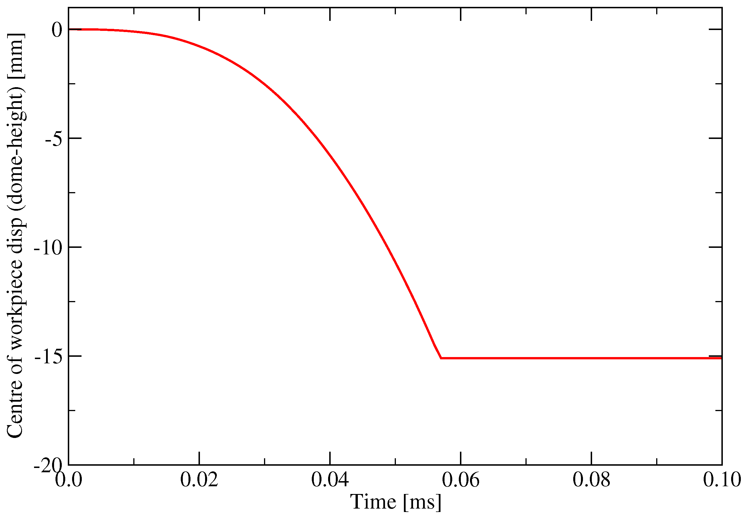
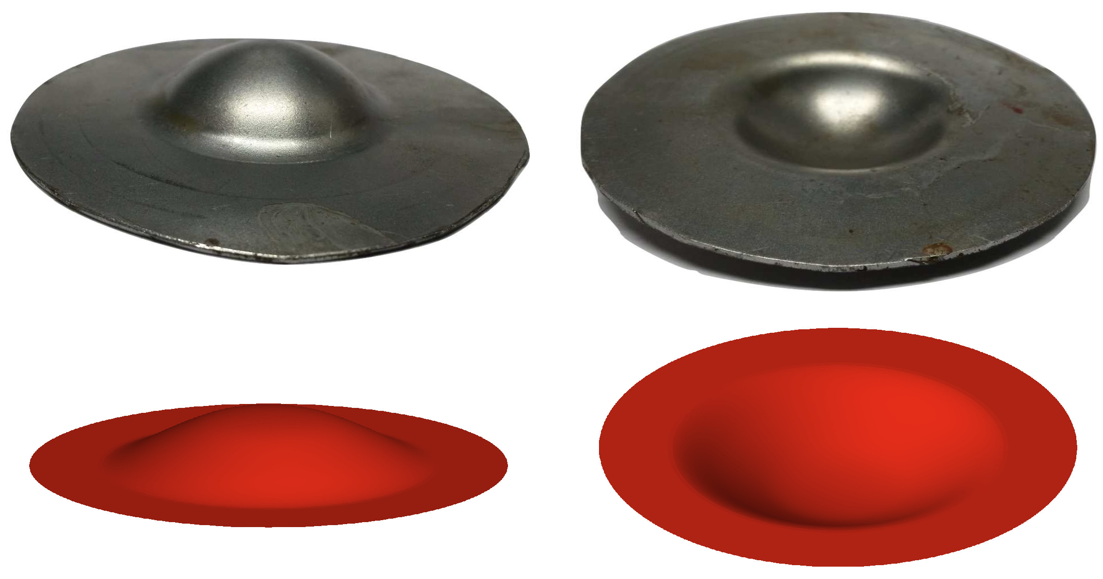
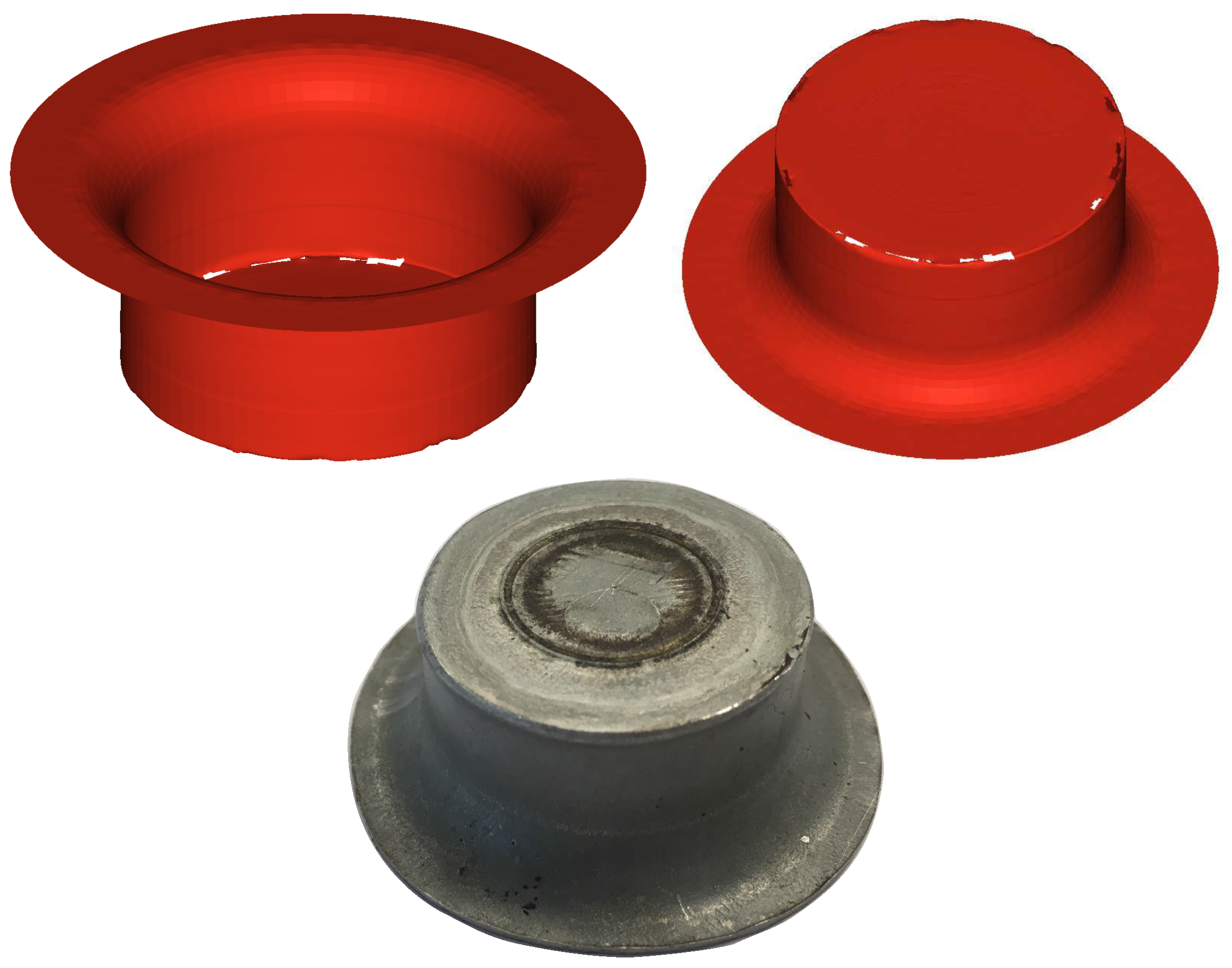
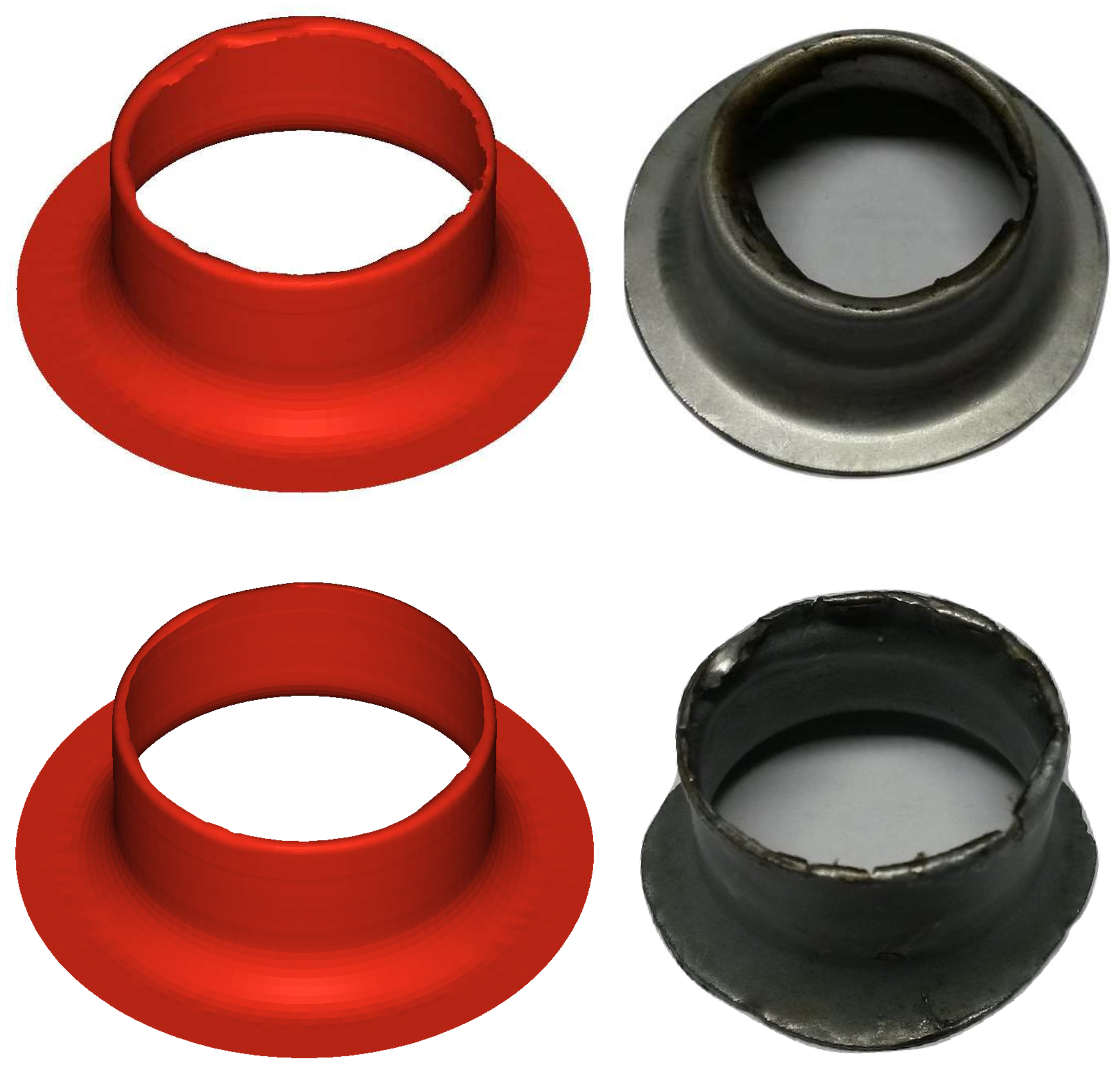
3.1. Cup Formation
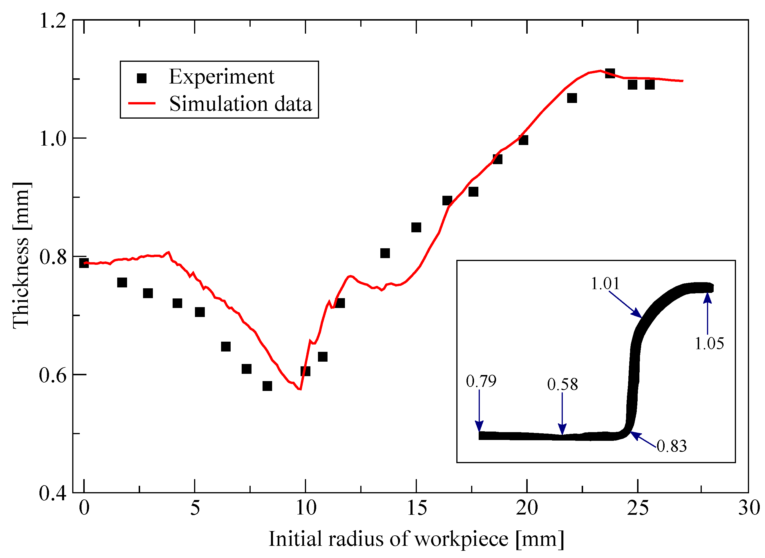
Thickness Variation
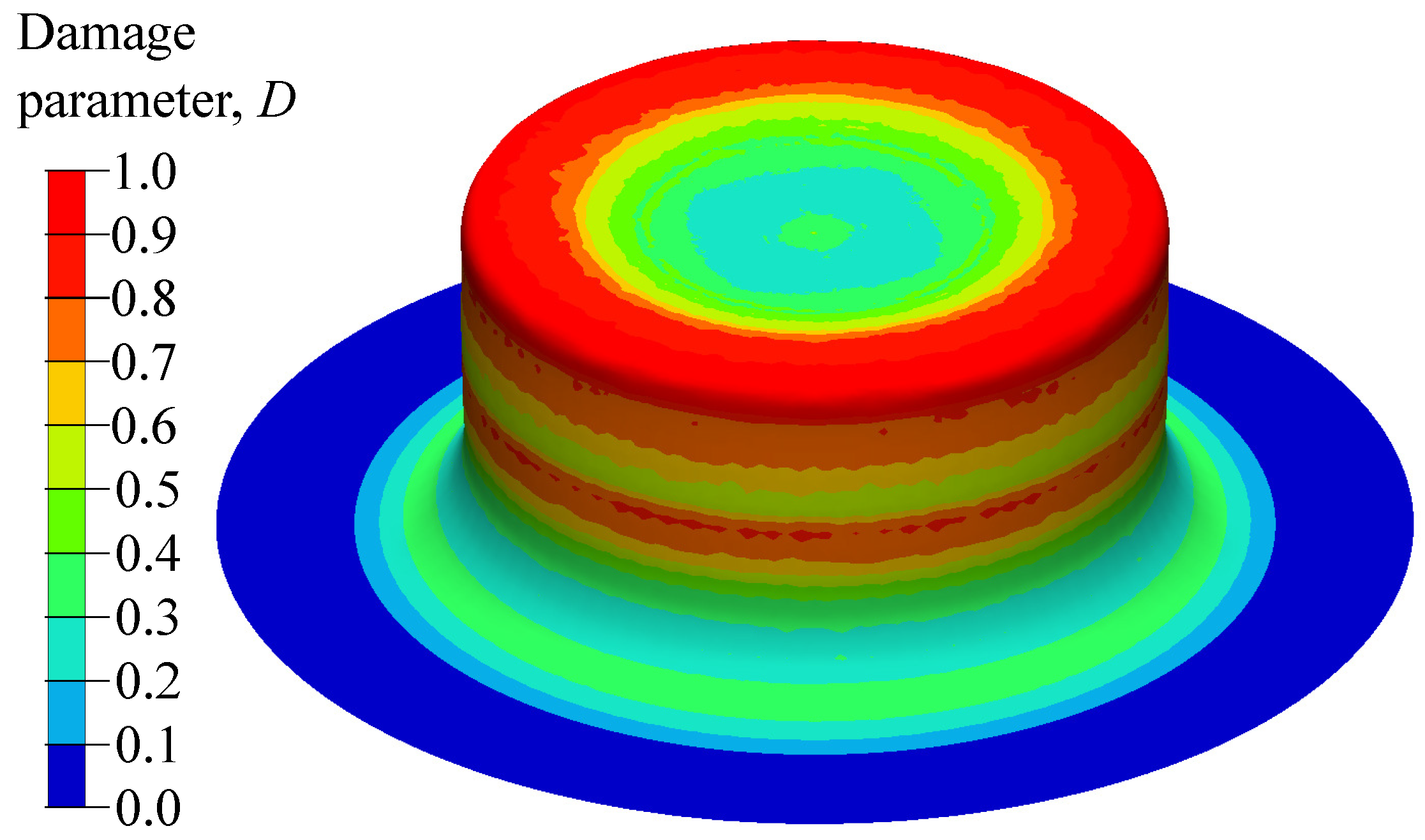
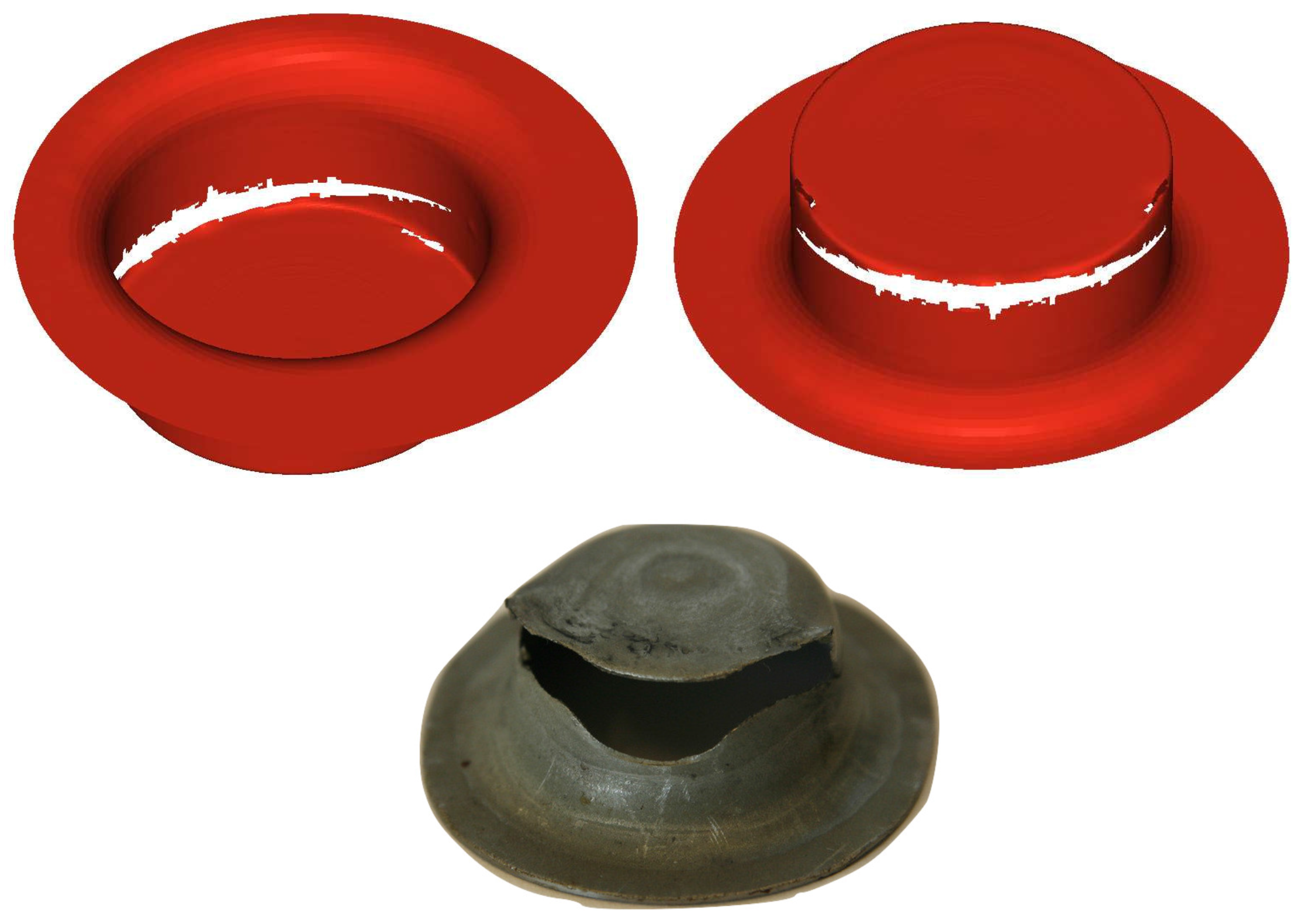
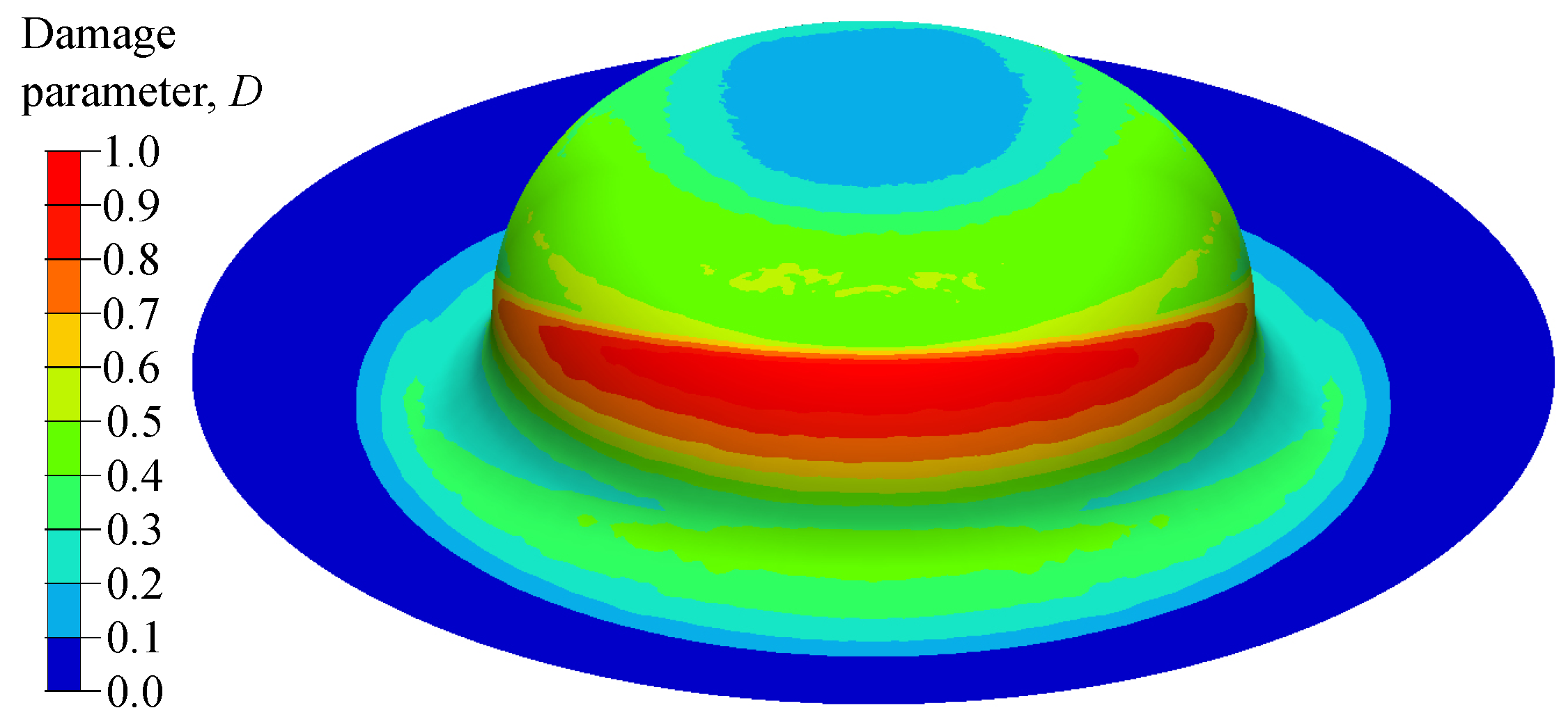
3.2. Damage in the Cup
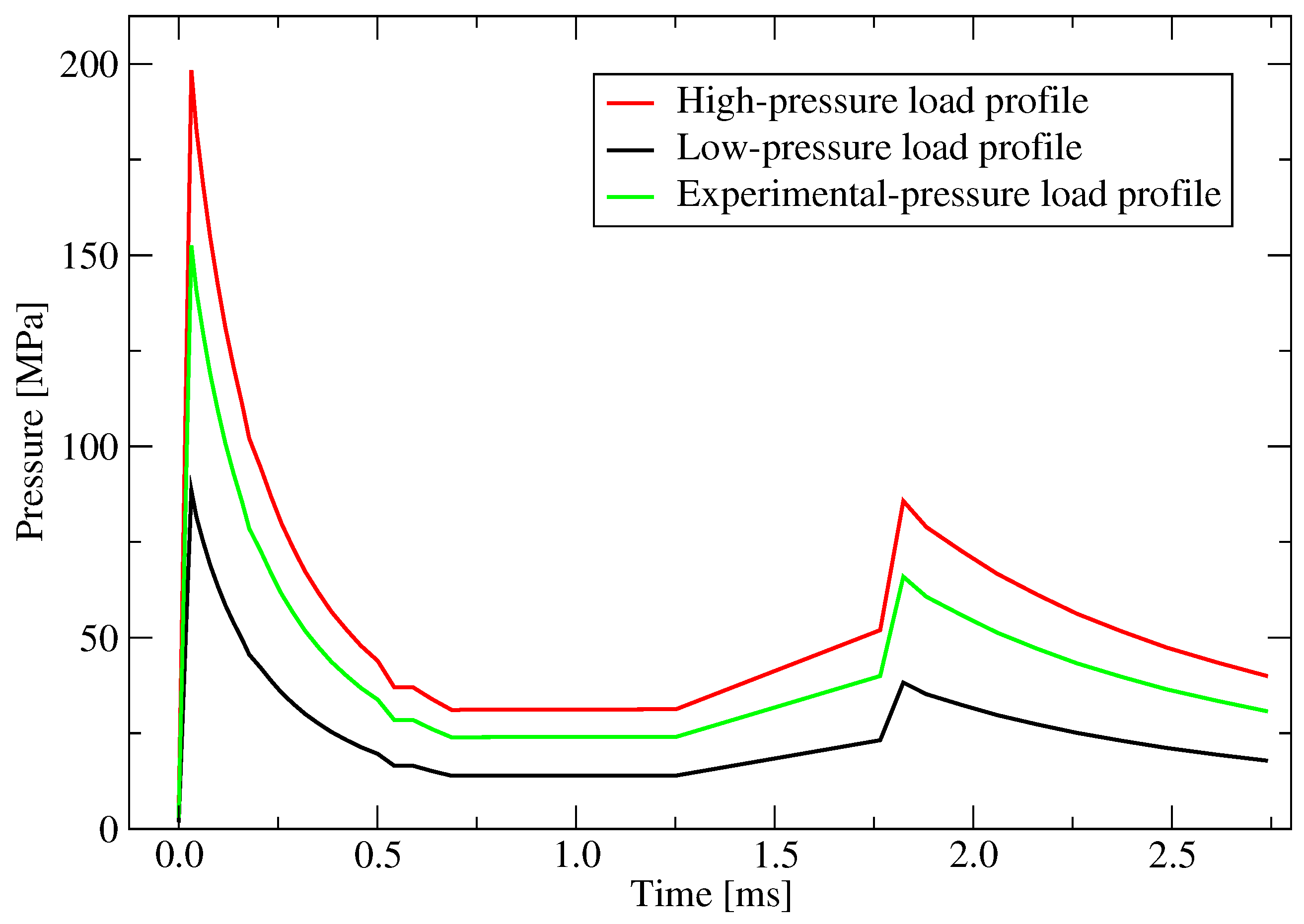
3.2.1. Pressure Magnitude
3.2.2. Effect of Offset
4. Conclusions and Future Work
Supplementary Materials
Acknowledgments
Author Contributions
Conflicts of Interest
References
- Bruschi, S.; Altan, T.; Banabic, D.; Bariani, P.; Brosius, A.; Cao, J.; Ghiotti, A.; Khraisheh, M.; Merklein, M.; Tekkaya, A. Testing and modelling of material behaviour and formability in sheet metal forming. CIRP Ann. Manuf. Techn. 2014, 63, 727–749. [Google Scholar] [CrossRef]
- Marré, M.; Brosius, A.; Tekkaya, A. New aspects of joining by compression and expansion of tubular workpieces. Int. J. Mater. Form. 2008, 1, 1295–1298. [Google Scholar] [CrossRef]
- Marré, M.; Brosius, A.; Tekkaya, A.E. Joining by compression and expansion of (none-) reinforced profiles. Adv. Mater. Res. 2008, 43, 57–68. [Google Scholar] [CrossRef]
- Marré, M.; Ruhstorfer, M.; Tekkaya, A.; Zaeh, M. Manufacturing of lightweight frame structures by joining of (None-) reinforced profiles. Adv. Mater. Res. 2008, 43, 2573–2584. [Google Scholar] [CrossRef]
- Marré, M.; Ruhstorfer, M.; Tekkaya, A.; Zaeh, M. Manufacturing of lightweight frame structures by innovative joining by forming processes. Int. J. Mater. Form. 2009, 2, 307. [Google Scholar] [CrossRef]
- Martins, P.; Bay, N.; Tekkaya, A.; Atkins, A. Characterization of fracture loci in metal forming. Int. J. Mech. Sci. 2014, 83, 112–123. [Google Scholar] [CrossRef]
- Psyk, V.; Risch, D.; Kinsey, B.; Tekkaya, A.; Kleiner, M. Electromagnetic forming—A review. J. Mater. Process. Technol. 2011, 211, 787–829. [Google Scholar] [CrossRef]
- Tekkaya, A.E. State-of-the-art of simulation of sheet metal forming. J. Mater. Process. Technol. 2000, 103, 14–22. [Google Scholar] [CrossRef]
- Shchelkin, K.I.; Troshin, Y.K. Gasdynamics of Combustion, 1st ed.; Mono Book Corporation: Baltimore, MD, USA, 1965. [Google Scholar]
- Honda, A.; Suzuki, M. Sheet metal forming by using gas imploding detonation. J. Mater. Process. Technol. 1999, 85, 198–203. [Google Scholar] [CrossRef]
- Mynors, D.J.; Zhang, B. Applications and capabilities of explosive forming. J. Mater. Process. Technol. 2002, 125, 1–25. [Google Scholar] [CrossRef]
- Yasar, M. Gas detonation forming process and modeling for efficient spring-back prediction. J. Mater. Process. Technol. 2004, 150, 270–279. [Google Scholar] [CrossRef]
- Yasar, M.; Demirci, H.I.; Kadi, I. Detonation forming of aluminium cylindrical cups experimental and theoretical modelling. Mater. Design. 2006, 27, 397–404. [Google Scholar] [CrossRef]
- El-Mokadem, A. Finite element modeling of sheet metal forming using shock tube. In Proceedings of the 9th International Conference Mechanical Design and Production (MDP-9), Cairo, Egypt, 8–10 January 2008. [Google Scholar]
- Wijayathunga, V.; Webb, D. Experimental evaluation and finite element simulation of explosive forming of a square cup from a brass plate assisted by a lead plug. J. Mater. Process. Technol. 2006, 172, 139–145. [Google Scholar] [CrossRef]
- Mousavi, S.A.; Riahi, M.; Parast, A.H. Experimental and numerical analyses of explosive free forming. J. Mater. Process. Technol. 2007, 187, 512–516. [Google Scholar] [CrossRef]
- Khaleghi, M.; Aghazadeh, B.S.; Bisadi, H. Efficient oxyhydrogen mixture determination in gas Detonation forming. Int. J. Mech. Mechatron. Eng. 2013, 7, 1748–1754. [Google Scholar]
- Babaei, H.; Mostofi, T.M.; Sadraei, S.H. Effect of gas detonation on response of circular plate-experimental and theoretical. Struct. Eng. Mech. 2015, 56, 535–548. [Google Scholar] [CrossRef]
- Babaei, H.; Mostofi, T.M.; Alitavoli, M.; Darvizeh, A. Empirical modelling for prediction of large deformation of clamped circular plates in gas detonation forming process. Exp. Technol. 2016, 40, 1485–1494. [Google Scholar] [CrossRef]
- Mirzababaie Mostofi, T.; Babaei, H.; Alitavoli, M. Experimental and theoretical study on large ductile transverse deformations of rectangular plates subjected to shock load due to gas mixture detonation. Strain 2017. [Google Scholar] [CrossRef]
- Mostofi, T.M.; Babaei, H.; Alitavoli, M. The influence of gas mixture detonation loads on large plastic deformation of thin quadrangular plates: Experimental investigation and empirical modelling. Thin-Walled Struct. 2017, 118, 1–11. [Google Scholar] [CrossRef]
- LS-DYNA Theory Manual; Livermore Software Technology Corporation: Livermore, CA, USA, 2006.
- Kleiner, M.; Hermes, M.; Weber, M.; Olivier, H.; Gershteyn, G.; Bach, F.W.; Brosius, A. Tube expansion by gas detonation. Prod. Eng. 2007, 1, 9–17. [Google Scholar] [CrossRef]
- Nikiforakis, N.; Clarke, J. Numerical studies of the evolution of detonations. Math. Comput. Model. 1996, 24, 149–164. [Google Scholar] [CrossRef]
- Johnson, G.R.; Cook, W.H. A constitutive model and data for metals subjected to large strains, high strain rates and high temperatures. In Proceedings of the 7th International Symposium on Ballistics, The Hague, The Netherlands, 19–21 April 1983; Volume 21, pp. 541–547. [Google Scholar]
- Verleysen, P.; Peirs, J.; Van Slycken, J.; Faes, K.; Duchene, L. Effect of strain rate on the forming behaviour of sheet metals. J. Mater. Process. Technol. 2011, 211, 1457–1464. [Google Scholar] [CrossRef]
- Schwer, L. Optional strain-rate forms for the Johnson Cook constitutive model and the role of the parameter Epsilon_0. In Proceedings of the 6th European LS-DYNA Users’ Conference, Frankenthal, Germany, October 2007; pp. 11–22. [Google Scholar]
- Schmitt, J.; Jalinier, J. Damage in sheet metal forming—I. Physical behavior. Acta Mater. 1982, 30, 1789–1798. [Google Scholar] [CrossRef]
- Jalinier, J.; Schmitt, J. Damage in sheet metal forming—II. Plastic instability. Acta Mater. 1982, 30, 1799–1809. [Google Scholar] [CrossRef]
- Johnson, G.R.; Cook, W.H. Fracture characteristics of three metals subjected to various strains, strain rates, temperatures and pressures. Eng. Fract. Mech. 1985, 21, 31–48. [Google Scholar] [CrossRef]
- Patil, S.P.; Popli, M.; Jenkouk, V.; Markert, B. Numerical modelling of the gas detonation process of sheet metal forming. J. Phys. Conf. Ser. 2016, 734, 032099. [Google Scholar] [CrossRef]
- Sullivan, J.F. Technical Physics, 99th ed.; Wiley: Hoboken, NJ, USA, 1988. [Google Scholar]
- Jenkouk, V.; Patil, S.; Markert, B. Joining of tubes by gas detonation forming. J. Phys. Conf. Ser. 2016, 734, 032101. [Google Scholar] [CrossRef]
- Hosford, W.F.; Caddell, R.M. Metal Forming: Mechanics and Metallurgy; Cambridge University Press: Cambridge, UK, 2011. [Google Scholar]
- Wang, X.; Shi, J. Validation of Johnson-Cook plasticity and damage model using impact experiment. Int. J. Impact Eng. 2013, 60, 67–75. [Google Scholar] [CrossRef]
- Zhang, D.N.; Shangguan, Q.Q.; Xie, C.J.; Liu, F. A modified Johnson–Cook model of dynamic tensile behaviors for 7075-T6 aluminum alloy. J. Alloys Compd. 2015, 619, 186–194. [Google Scholar] [CrossRef]
- Buchkremer, S.; Wu, B.; Lung, D.; Münstermann, S.; Klocke, F.; Bleck, W. FE-simulation of machining processes with a new material model. J. Mater. Process. Technol. 2014, 214, 599–611. [Google Scholar] [CrossRef]


| Property | Value |
|---|---|
| Young’s modulus (GPa) | 180 |
| Poisson’s ratio | 0.3 |
| Density (kg/m) | 7870 |
| Tensile strength (MPa) | 210 |
| Property | Value |
|---|---|
| Yield stress, A (MPa) | 162 |
| Strength coefficient, B (MPa) | 598 |
| Deformation hardening, n | 0.6 |
| Strain rate coefficient, C | 2.623 |
| Deformation sensitivity, m | 0.009 |
| Property | Value |
|---|---|
| 0.02 | |
| 3.9 | |
| 4.6 | |
| 0.002 |
© 2017 by the authors. Licensee MDPI, Basel, Switzerland. This article is an open access article distributed under the terms and conditions of the Creative Commons Attribution (CC BY) license (http://creativecommons.org/licenses/by/4.0/).
Share and Cite
Patil, S.P.; Prajapati, K.G.; Jenkouk, V.; Olivier, H.; Markert, B. Experimental and Numerical Studies of Sheet Metal Forming with Damage Using Gas Detonation Process. Metals 2017, 7, 556. https://doi.org/10.3390/met7120556
Patil SP, Prajapati KG, Jenkouk V, Olivier H, Markert B. Experimental and Numerical Studies of Sheet Metal Forming with Damage Using Gas Detonation Process. Metals. 2017; 7(12):556. https://doi.org/10.3390/met7120556
Chicago/Turabian StylePatil, Sandeep P., Kaushik G. Prajapati, Vahid Jenkouk, Herbert Olivier, and Bernd Markert. 2017. "Experimental and Numerical Studies of Sheet Metal Forming with Damage Using Gas Detonation Process" Metals 7, no. 12: 556. https://doi.org/10.3390/met7120556
APA StylePatil, S. P., Prajapati, K. G., Jenkouk, V., Olivier, H., & Markert, B. (2017). Experimental and Numerical Studies of Sheet Metal Forming with Damage Using Gas Detonation Process. Metals, 7(12), 556. https://doi.org/10.3390/met7120556