Article

Case Studies on Local Reinforcement of Sheet Metal Components by Laser Additive Manufacturing

by
Markus Bambach
1,*,
Alexander Sviridov
1,
Andreas Weisheit
2 and
Johannes Henrich Schleifenbaum
2,3
1
Mechanical Design and Manufacturing, Brandenburg University of Technology Cottbus-Senftenberg, Konrad-Wachsmann-Allee 17, 03046 Cottbus, Germany
2
Fraunhofer Institute for Laser Technology ILT/Chair for Laser Technology LLT, RWTH Aachen, Steinbachstraße 15, 52074 Aachen, Germany
3
Digital Additive Production, RWTH Aachen, Steinbachstraße 15, 52074 Aachen, Germany
*
Author to whom correspondence should be addressed.
Metals 2017, 7(4), 113; https://doi.org/10.3390/met7040113
Submission received: 31 December 2016 / Revised: 15 March 2017 / Accepted: 20 March 2017 / Published: 25 March 2017
(This article belongs to the Special Issue 3D Printing of Metals)

Abstract

:
This paper details two case studies that make use of laser metal deposition for local reinforcement of sheet metal components. Two benchmark scenarios are investigated, both using aluminum alloys: (i) using laser cladding to increase the stiffness of a pre-formed component, and (ii) applying a local cladding on sheet metal for increasing the thickness prior to a hole-flanging operation. The results show that both routes are viable. Applying claddings onto sheet metal before a metal forming operation must ensure suitable formability, which may be limited by the layer material and undesired changes in the microstructure of the sheet. The limited formability has to be taken into account in the design of the forming operation. Cladding onto already formed components has to cope with inevitable distortion of the component. Nevertheless, introducing additive manufacturing into the field of sheet metal forming opens the possibility to produce new products such as tailored laser-cladded blanks, combinations of sheet and bulk components and to develop new methods such as stiffness management in lightweight design.

1. Introduction

In many applications, local reinforcement of sheet metal components may be necessary or desired, e.g.:
  • to support highly loaded areas that bear fasteners or joints;
  • to create functional elements;
  • to compensate for sheet thinning occurring during metal forming operations;
  • to manufacture parts for vehicle derivatives from series parts;
  • for acoustic reasons or
  • for corrosion and wear protection.
Figure 1 shows a typical application where a local reinforcement would be useful to improve the performance of the component without resorting to a sheet metal of increased thickness. The rivet nut in Figure 1a could be replaced by a formed flange (created by a hole-flanging operation) into which a thread is cut. This solution would save weight and reduce the risk of corrosion attack. Replacing the rivet nut by a formed flange is only feasible if the flange provides sufficient sheet thickness. Flanging operations, however, typically lead to sheet thinning, as shown in Figure 1b.
Tailored blanks and patchwork blanks [1] are semi-finished products with a variable thickness. They allow for material cost savings of up to 10% [2] and can have thickness differences of up to 50% within a steel strip/blank [3]. Three main types of tailored blanks can be distinguished [1], Figure 2:
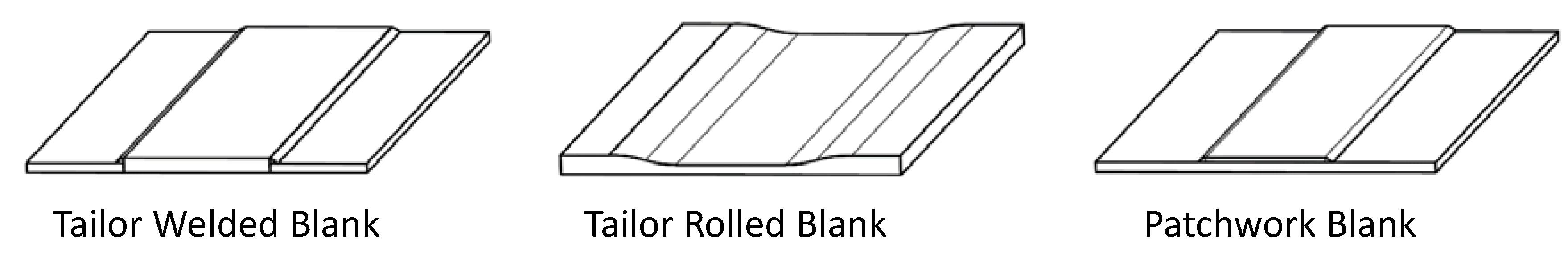
  • Tailor Welded Blanks (TWB), where sheet metal blanks with a different thickness are joined by a welding process;
  • Tailor Rolled Blanks (TRB), where thickness variations in the sheet metal are accomplished by changing the roll gap height during rolling; and
  • Patchwork Blanks (PB), where a local increase in the sheet thickness is made possible by welding, gluing or soldering sheet metal patches onto sheet metal blanks.
As shown in Figure 2, both the geometry of the thickened zones and the course of the sheet thickness are geometrically limited with commercially available tailored blanks. Even patchwork blanks, the most flexible variant of tailored blanks, have several limitations from a technological and economic point of view, including:
  • a constant, not load-optimized thickness of the patch;
  • the production of scrap during blanking of the patches;
  • a high susceptibility to corrosion in the gap between sheet metal and patch;
  • a problematic further processing (including low formability and springback);
  • with patches attached by gluing a high susceptibility to ageing.
A possible solution for the application shown in Figure 1 is to manufacture local reinforcements using emerging additive manufacturing processes such as Laser Metal Deposition (LMD). In this paper, the term ‘laser cladding’ will be used, which stands for the same technology but is more precise with respect to the fact that layers are deposited. The principle of laser cladding is shown in Figure 3. The laser beam melts a thin layer of the substrate as well as the introduced powder particles, leading to a layer with nearly 100% density and metallurgical bonding to the substrate. The powder is fed by a disc feeder in a carrier gas stream of argon. The carrier gas also shields the melt pool from the surrounding atmosphere [4]. The method is primarily used for local wear protection [5] and for the repair of high-quality components, e.g., jet-engine parts [6]. Compared to other cladding methods like PTA (Plasma Transferred Arc) laser cladding has the advantage of high precision and minimum heat input. However, the deposition of the material to the component can lead to intolerable distortion of the sheet so that it is possibly more advantageous to use it to reinforce the semi-finished product.
Basic knowledge about the possibilities of using additive manufacturing for local modification of semi-finished products and components as well as comparative studies of the properties and economy compared to available solutions are lacking at the moment. This work details two case studies investigating the possibilities offered by laser cladding for increasing the sheet thickness of semi-finished and formed components.

2. Materials and Methods

2.1. Materials

The nominal compositions of the materials used are listed in Table 1. As sheet material, the aluminum alloy EN AW 6082 was chosen. As powder material, two similar Al-Si-alloys were chosen that exhibit good performance in laser additive manufacturing [7]. For both alloys, experience and parameters for laser cladding are available at the Fraunhofer ILT (AlSi10Mg) and BTU Cottbus-Senftenberg (AlSi12); therefore, no parameter studies for cladding had to be conducted. However, it should be noted that for the demonstrator II (see Section 2.4) a limited formability of the cladded layer will result due to the high Si content. The demonstrator is formed by a hole-flanging operation with fairly limited plastic deformation. Future investigations will include wrought aluminum alloys to allow for larger plastic deformation.

2.2. Overview of Application Scenarios

The case studies investigated in the remainder of this work represent two application scenarios of local reinforcements and two different process chains:
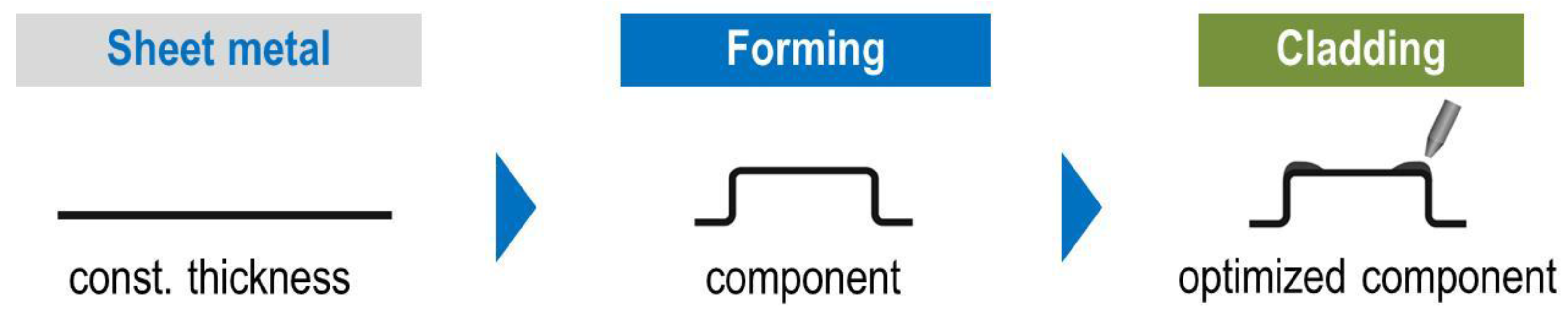
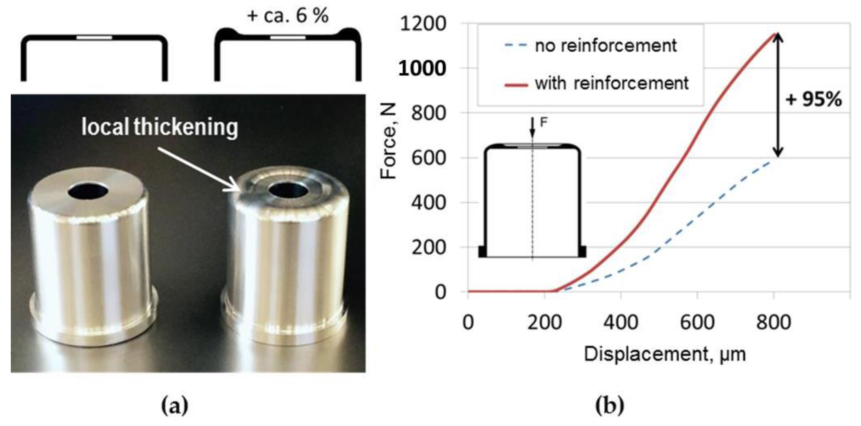
  • In the first case, cladding is applied to the formed component: the increase in sheet thickness improves the stiffness of the component. In this case, a sizing operation (numerical optimization) needs to be performed to determine the optimal thickness profile.
    Metals 07 00113 i001
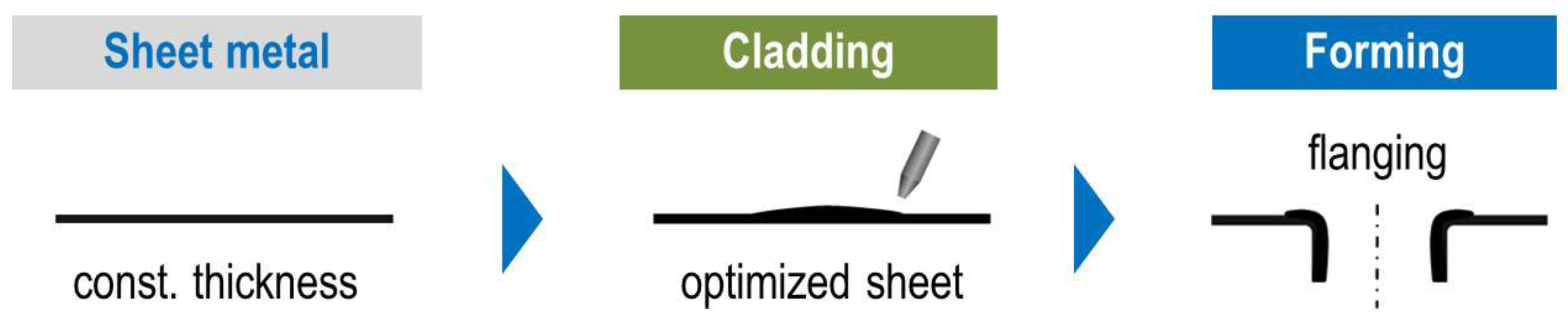
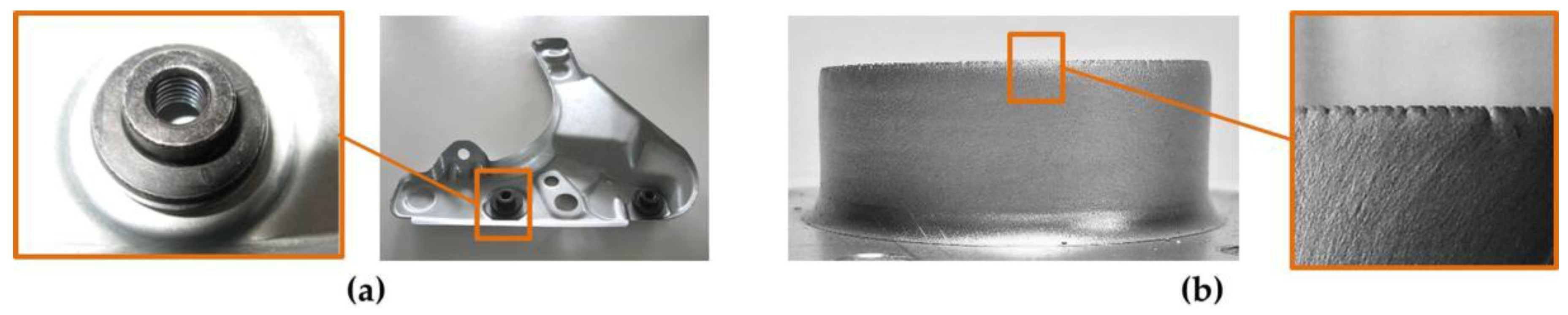
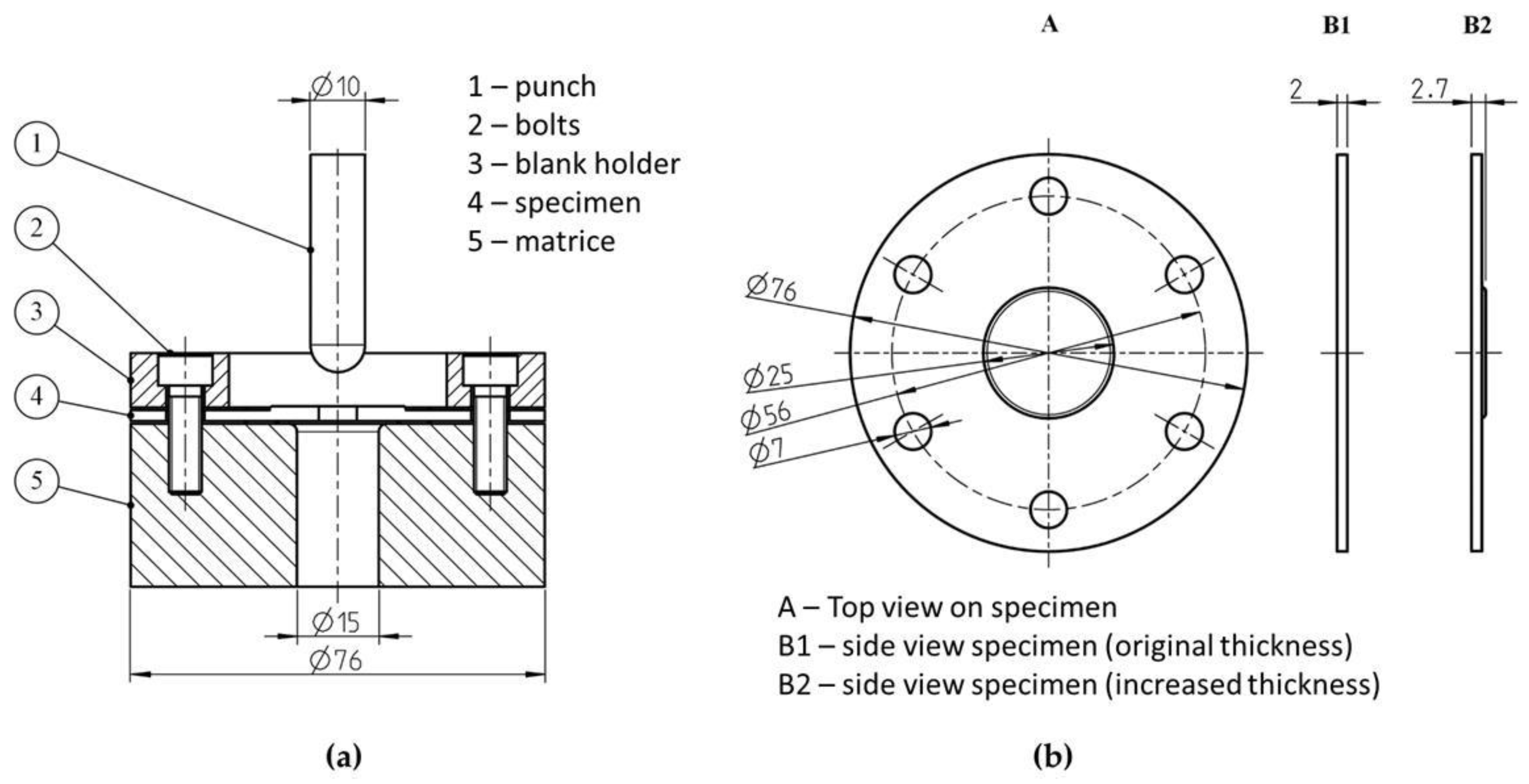
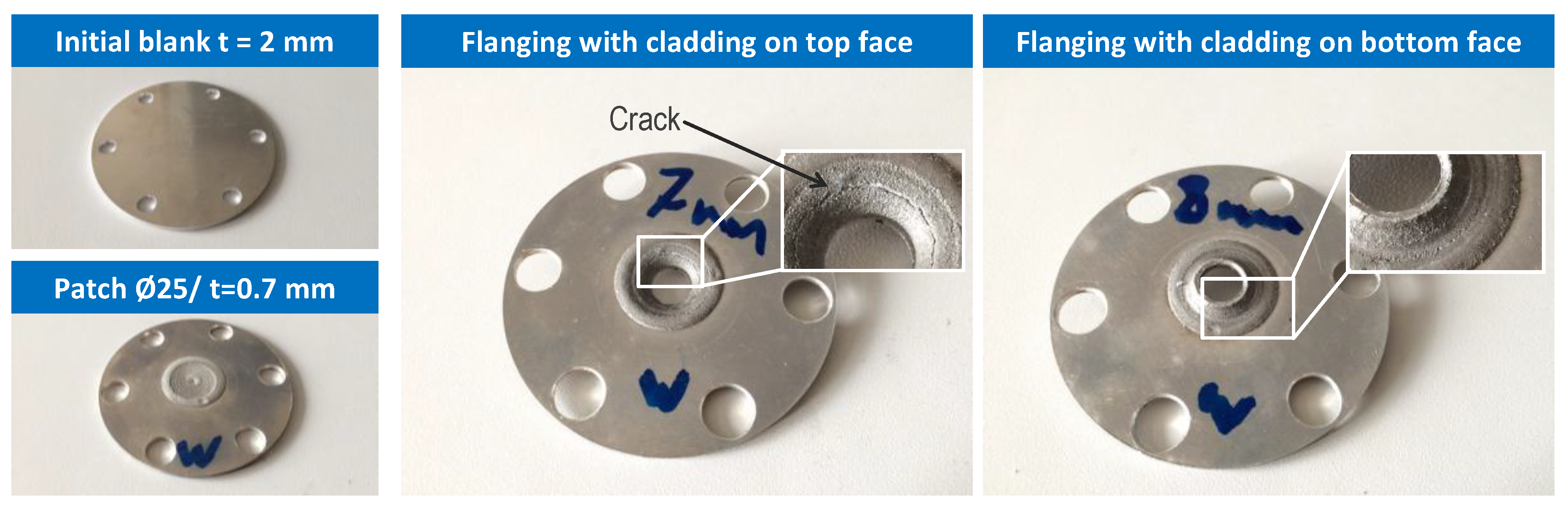
  • In the second case, laser cladding is applied to the semi-finished product before forming: as forming operation, hole flanging is considered. Since flanging may reduce the sheet thickness, thickening by cladding may allow the desired minimum sheet thickness to remain, e.g., for cutting a thread into the flange, as shown in Figure 1.
    Metals 07 00113 i002
In the following, both routes are described individually.

2.3. Demonstrator I: Stiffness Management of Pre-Formed Part

2.3.1. Demonstrator Geometry and Optimization Task

An idealized suspension dome made of the aluminum wrought alloy EN AW 6082 is used as a demonstrator (Figure 4) to analyze the possibility of stiffness management by local, additively manufactured reinforcements. The basic part shown in Figure 4a is a cylindrical cup with a wall thickness of 1 mm and a central hole in the top face. In a real suspension dome, the suspension would be fastened to the central hole, which would transmit the suspension forces into the car body structure.
Based on the given component geometry, we look for possibilities to increase the part stiffness under the central load using a minimum of added material. Such an increase in stiffness could be required in a variant with a heavier engine or, alternatively, simply to save weight. Thus, we look for a thickness distribution that minimizes the deflection of the hole edge and design it using patchwork blanks, Figure 4b, and using a laser-cladded reinforcement, Figure 4c. The total added material volume is equal in both cases. The case study should show the advantages of the stiffness-optimized variant compared to the basic variant and the patchwork blank.
To define the geometry of the laser cladding, a sizing optimization of the basic variant was carried out using Abaqus/TOSCA to determine an optimal non-linear thickness distribution resulting in a substantial increase in stiffness. The rim around the central hole was loaded with a vertical force of 600 N, which is low enough to cause only elastic deflection. In the sizing optimization, the top face of the part was selected as design region. The area around the central hole was excluded to account for the fact that a flat region is needed to apply the external load. This would also be the case in a real suspension dome.
The solver minimizes the displacement of the loaded rim under the constraint that the added material volume must not exceed the volume of the patch with a cross section of 1 × 4 mm in Figure 4b. Also, a maximum thickness increase of 1 mm is specified. The result of sizing optimization is compared to the stiffness of both other cases. The comparison of all cases was performed using finite element analysis. In addition, laser cladding experiments were carried out to produce the tailored cladding shown in Figure 4c. The stiffness of the basic variant and of the part with local reinforcement was tested in experiments under static loads.

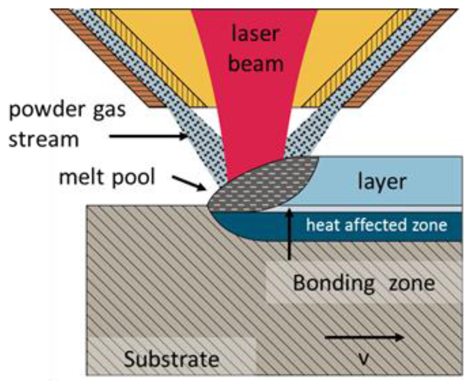
2.3.2. Laser Cladding Experiments

In order to approach the solution with reinforcement, experimental trials using laser cladding were performed. A ring-shaped thickening of AlSi10Mg with a width of 4 mm, a thickness of 1 mm and an outer diameter of 40 mm was applied to a pre-shaped sample (alloy EN AW 6082) with a wall thickness of 1 mm, according to Figure 4a. The laser source was a fiber coupled diode laser (λ = 1025 and 1040 nm) with an output power of 2 kW. The beam diameter was 0.6 mm, the intensity distribution top hat. The beam followed a spiral path with a pitch of 0.3 mm per revolution. Cladding was performed with a feed of 4000 mm/min, a laser power of 860 W and a powder feed rate of 1.2 g/min. Three layers had to be cladded to achieve the desired thickness. A laser clad specimen was cut and a cross section was prepared using standard metallographic techniques.

2.3.3. Testing of Component Stiffness

In order to estimate the potential of the local reinforcement, thickened by tailored laser cladding (Figure 4c) and non-thickened (Figure 4a) components were tested under static loads in a Zwick Z250 testing machine (Zwick GmbH & Co. KG, Ulm, Germany). Surface machining operations were applied before testing to improve the surface quality and to correct the geometry for precise comparison of the results. Furthermore this allows a parallel alignment of the top face where the load is applied to the bottom pedestal. During the experiments the force-displacement characteristics were recorded.

2.4. Demonstrator II: Flanging of Locally Clad Sheet

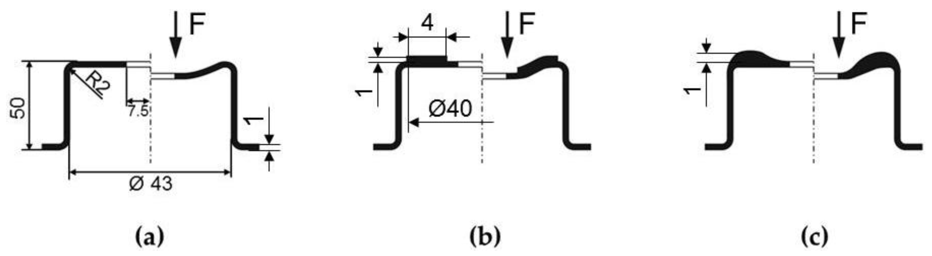
2.4.1. Demonstrator Geometry

This demonstrator is concerned with the manufacturing of a local cladding on sheet metal blanks, which are subsequently processed by hole flanging. Hole flanges are important functional elements in many sheet metal parts. They provide stiffness, allow for positioning and fixation, etc. Increasing the wall thickness of the flange may be necessary for subsequent operations such as cutting a thread into the flange, as detailed in the introduction of the paper. The case study comprises the manufacturing of cladded blanks in two different variants, cladding on the outside of the flange, Figure 5a, and on the inside of the flange, Figure 5b.

2.4.2. Production of Tailored Laser-Cladded Blanks

As sheet metal, the aluminum alloy EN AW 6082 was chosen, as in the first demonstrator. Circular blanks of 2 mm thickness and 76 mm diameter were cut. As powder for laser cladding, the cast alloy AlSi12 was used. A Trumpf TruLaser Cell 7040 (TRUMPF GmbH & Co. KG, Ditzingen, Germany) operated with a CO2 laser with a maximum power of 5000 W was used for cladding. The sheet metal blank was cooled during the welding process using a water-cooled aluminum plate, which was positioned below the sample. At the same time, the specimen was held in place by a fixture system to reduce the heat-induced warping. Claddings with a diameter of 20 mm and a thickness of 0.75 mm were programmed. The final height of the cladding relative to the base sheet was 0.7 mm on average. A laser power of 3400 W, a feed rate of 400 mm/min, a powder mass flow rate of 1.6 g/min and a mixture of helium and argon as shielding gas were used as process parameters. Three cladding strategies were investigated (Figure 6).

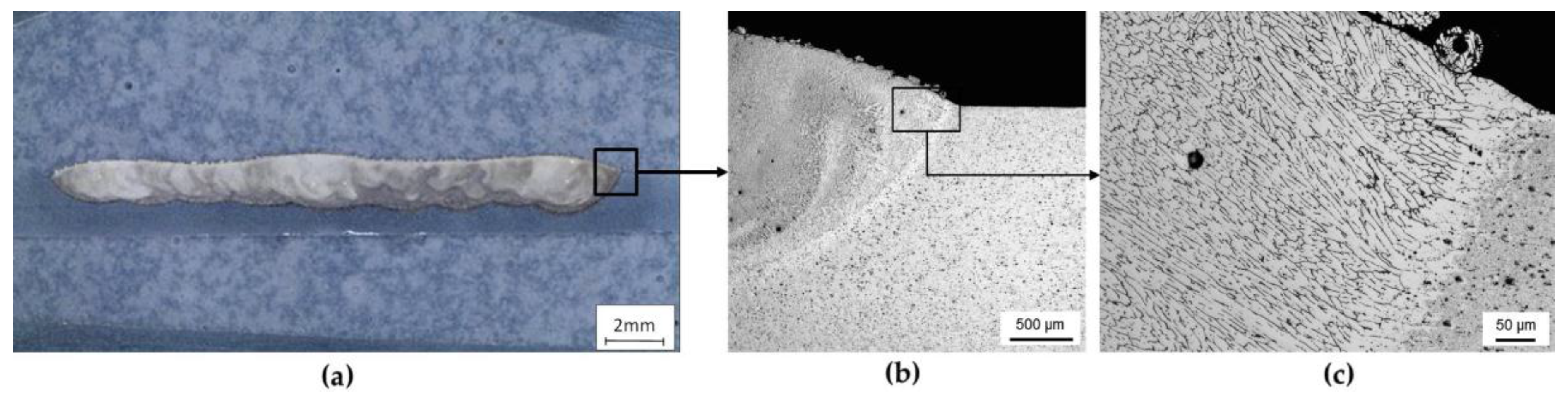
2.4.3. Light Optical Microscopy (LOM)

Laser-cladded specimens were cut and cross sections were prepared. The samples were ground flat with successively finer grades of SiC paper and then diamond polished until all deep scratches from grinding were removed (9 µm/for 10 min, 3 µm/for about 30 min, 1 µm/for 5 min). In the final stage, the samples were etched with Keller reagent (3 mL HCl + 5 mL HNO3 + 1 mL HF + 190 mL water) for revealing the ‘weld microstructure’. The microscopic examination of the etched samples was conducted using an optical microscope from Leica Mikrosysteme Vertrieb GmbH, Wetzlar, Germany.

2.4.4. Hole-Flanging Experiments

Hole-flanging operations in sheet metal parts are typically performed using a punch that deforms a pierced sheet metal into a matrix, see Figure 7a. The sheet metal is clamped using a blank holder. In the case considered here, the area deformed by the flanging operation is thickened using laser cladding. The specimen geometry is shown in Figure 7b.
Table 2 gives an overview of the experimental tests that were performed. In addition to samples with a cladding of 0.7 mm on specimens with 2.0 mm thickness, monolithic sheet metal of 2.0 mm and 2.5 mm thickness was tested. The thickness of the inclad specimens corresponds to the clearence between punch and matrice for t = 2.5 mm and is smaller in the case of t = 2 mm. For the cladded specimens, a slightly larger thickness was chosen to exert pressure during forming, hence decreasing the chance to damage the relatively brittle clad material.

3. Results

3.1. Results for Demonstrator I—Stiffness Management

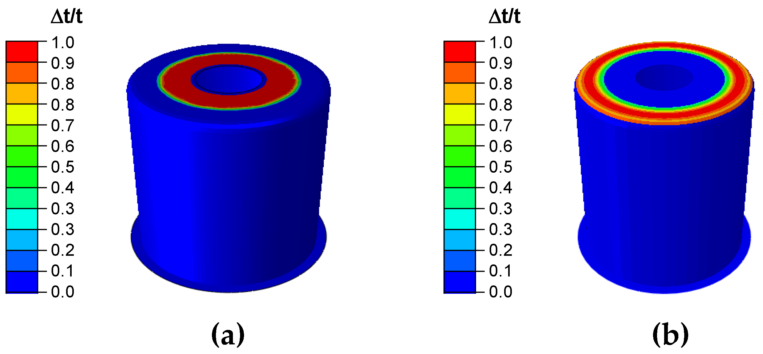
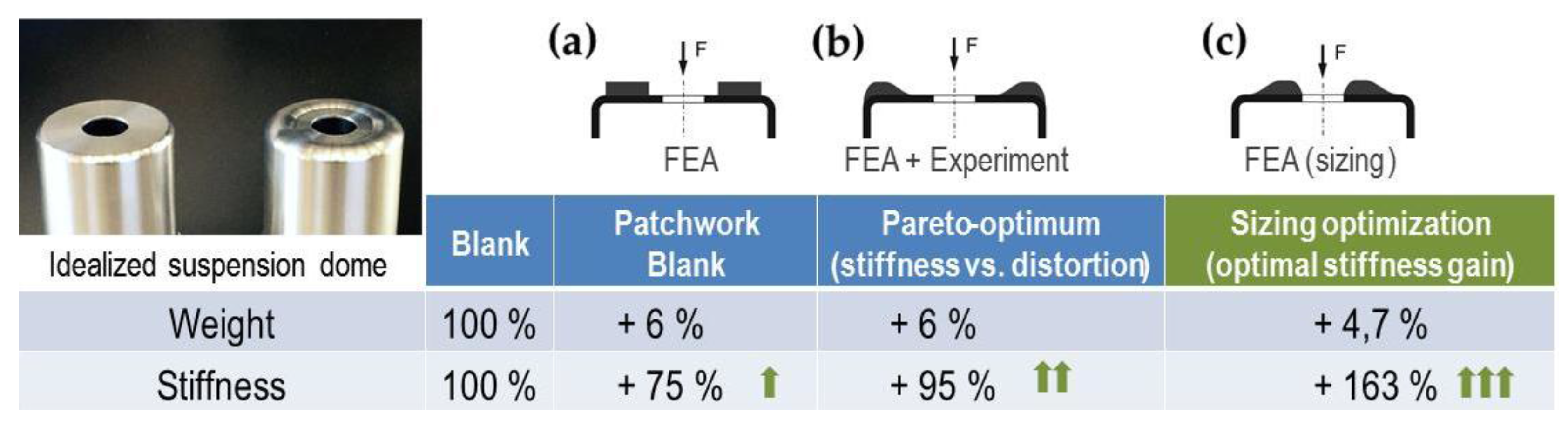
3.1.1. Results of the Sizing Optimization

The solution of the sizing optimization is shown in Figure 8 in terms of thickness increase vs. thickness of base material. An optimal increase in stiffness under the given mass constraint is obtained by a non-linear increase in sheet thickness in a ring-shaped area close to the central hole. Sizing optimization yields a smooth transition between thickened area and the flat top face of the component towards the outer radius of the part, and a jump in sheet thickness towards the central hole.
Obviously, a maximum increase in stiffness is achieved by supporting the edge of central hole with additional material. However, laser cladding close to the unsupported inner hole leads to a significantly higher risk of distortion than in the case of cladding at the outer edge of the dome. To evaluate the influence of the position of the cladded layer on the distortion simulations of the plastic strain caused by the laser cladding process were performed. To this end, single circular paths of the laser cladding process were simulated and the occurrence of plastic deformation was monitored. According to the experimental settings, the beam diameter was set to 0.6 mm, the feed rate was 4000 mm/min and the laser power was 860 W. The moving laser spot is simulated as moving heat source using the user subroutine *DFLUX in the ABAQUS finite element solver. The top hat distribution used in the experiment is specified through this routine. Laser spot size, power and feed rate match the experimental values. It is assumed that 60% of the laser energy are absorbed by the material in accordance with earlier investigations. The simulation considered only the heat input by the laser source and no powder flow and build-up volume. It is therefore only a rough estimation of the stresses and strains occurring. The results given in Figure 9 show that circular laser paths close to the inner hole lead to small plastic deformation, i.e., permanent distortion of the component. For a distance of more than 15 mm from the center, no plastic deformation is observed.
Based on these findings, a second design was calculated which penalizes the distance to the center hole, i.e., the closer the thickness increase is situated to the central hole, the higher the penalty, Figure 8b. This led to a second, pareto-optimal variant which is compared to the initially found design and to the reference cases of a homogeneous thickness and a patchwork blank in the following.

3.1.2. Microstructure of the Cladding

Figure 10 shows a cross section of the cladded layers, which exhibits the typical fine dendritic microstructure of primary solidified Al crystals (light) and interdendritic solidified Si (dark). Firm bonding to the substrate is observed.

3.1.3. Stiffness Properties of the Reinforced Parts

Figure 11 shows the results obtained by testing the basic variant and the optimized design which contains a thickened area in the radius region. In this case, with six percent added mass, a stiffness increase of 95% was obtained. This is more than the stiffness increase obtained with a patchwork blank of constant thickness. Figure 12b shows a comparison to a patchwork blank that uses a patch of the same mass as the produced cladding. The chosen design still outperforms the patchwork blank but falls behind the possibilities offered by sizing optimization, Figure 12c. This solution increases the stiffness by 163% with only 4.7% added mass, but will probably lead to distortion of the component.

3.2. Results for Demonstrator II—Hole-Flanging of Tailored Laser-Cladded Blanks

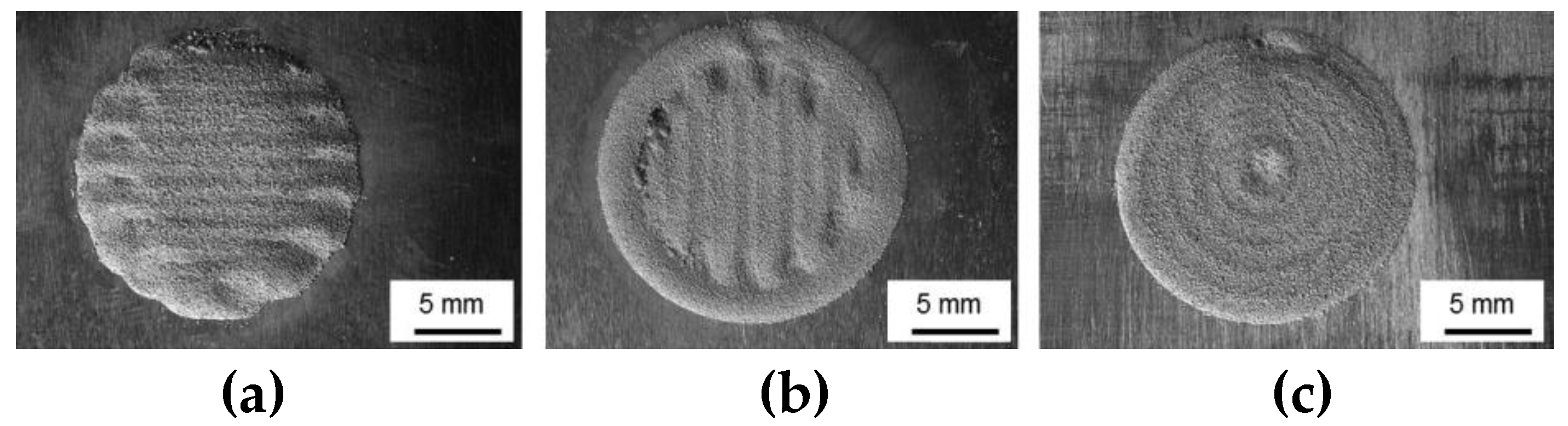
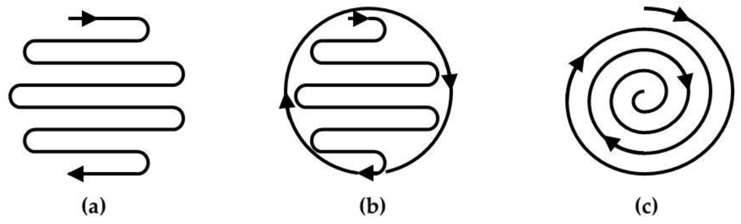
3.2.1. Laser Cladding Strategies

Figure 13 shows the results of the three different cladding strategies, revealing that strategy with the spiral path of the laser beam (Figure 13c) yields the cladding with the most appropriate surface. Strategies with straight path with parallel offset of the laser beam (Figure 13a,b) did not allow to produce claddings without defects in the start and end positions.

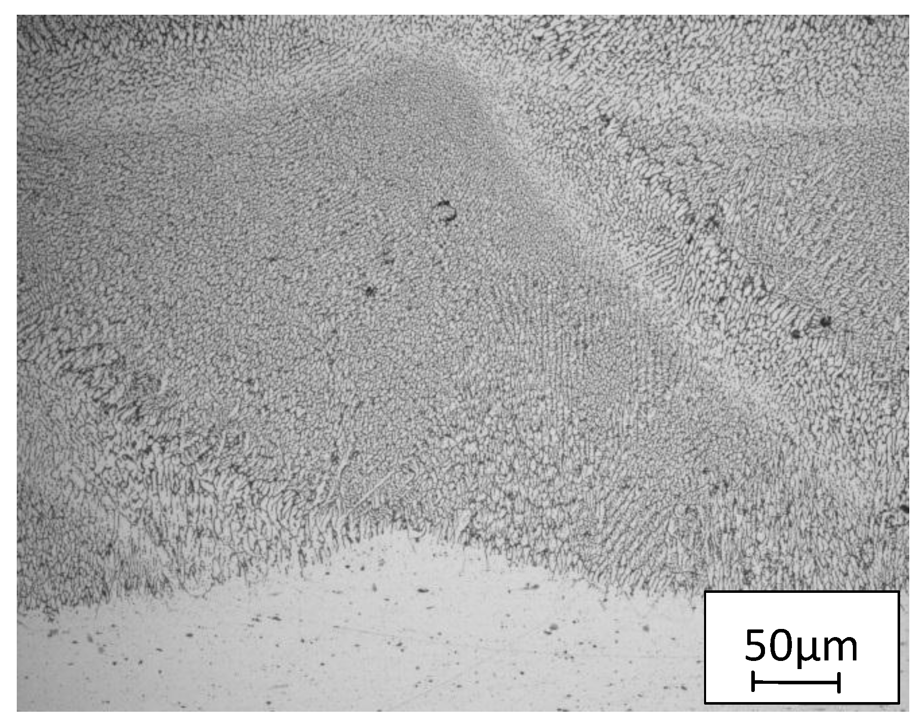
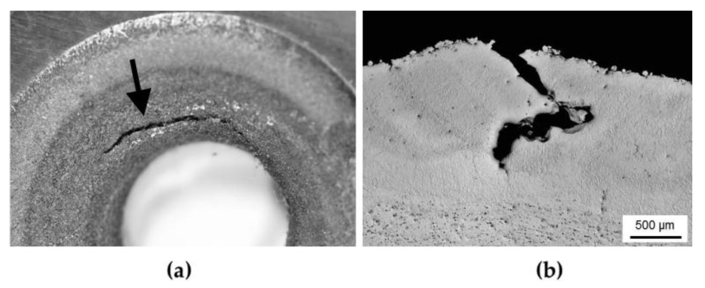
3.2.2. LOM of the Cladding

The cladding shown in Figure 13c was analyzed metallographically. The interface between base material and clad layer is shown in Figure 14. The micrographs indicate a good connection between the base material and the deposited layers. Three different zones can be distinguished: the deposition layer, a thin heat affected zone and the base material. The former solid–liquid interface deeply penetrates into the substrate which results in about 50% dissolution between base and clad material. It can be seen that the solidification of the melt starts at the boundary of the base material in a columnar way. The high cooling rate associated with a rapid solidification promotes a fine dendritic microstructure in the deposited layer. The transition between cladding and base material is smooth. Hence, no stiffness jump and no stress localization are to be expected, which may be advantageous compared to patchwork blanks. The samples showed some porosity of the clad layer. A pore is magnified in Figure 14c.

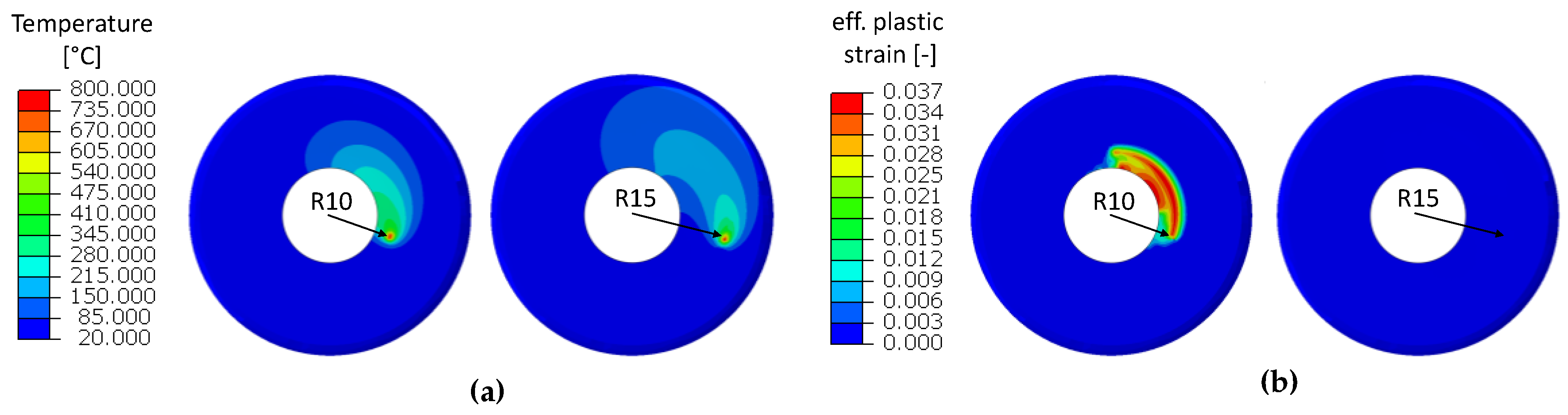
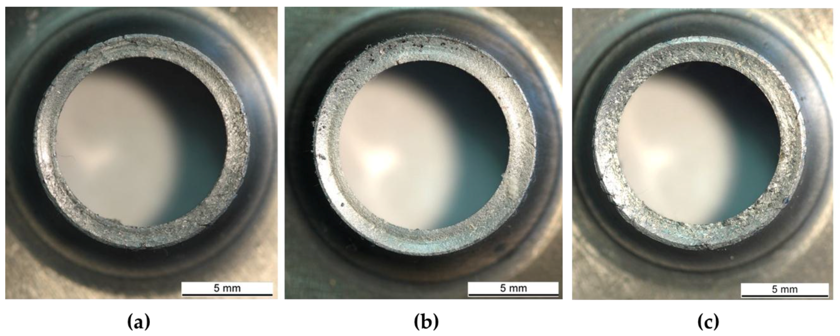
3.2.3. Hole-Flanging Experiments

The results of the flanging experiments show that the flanging operation with monolithic sheet metal was feasible with all hole expansion ratios (cf. Table 2). For the specimens with a cladding on the inside of the flange (facing the punch), cracks were observed in the radius of the flange, which is stretched during forming. Cladding on the outside of the flange led to failure primarily in the edge of the cut hole. Examples of these failures are shown in Figure 15. Figure 16b shows a micrograph through a crack that was generated in the cladding during forming. The curvature of the crack propagation indicates that the crack has formed along the grain boundaries where the brittle Si phase is concentrated. Figure 17 shows the results of successful flanging experiments with and without cladding, with machined holes of seven-millimeter radius.

4. Discussion

The results obtained in the two case studies will be discussed regarding general viability and applicability of laser cladding to sheet metal components, as well as regarding production time and material efficiency:
General viability and scope of application. Two application scenarios were studied which use laser cladding for local reinforcement of sheet metal components, i.e., local cladding of a component for increased stiffness and local cladding to increase the sheet thickness in the wall of a flange produced by hole flanging.
Laser cladding of an already manufactured component opens up the possibility to use additive manufacturing for stiffness management, a new field of application. The challenge here is not the cladding process of a suitable material but the reduction of distortion and a minimum change in the microstructure (and thus the properties) of the base material. Since laser cladding would be the last process step in the manufacturing route of the component, straightening and often also a heat treatment is no option. Future work has to focus on sizing optimization (minimized clad areas and clad thickness), on strategies to quickly extract the heat by cooling and to explore adequate cladding strategies which minimize distortion.
Cladding a sheet prior to forming also causes distortion, which must be handled in the same way as for cladding on an already formed component (see above). However, straightening might also be an option. A major issue is the formability of the laser-cladded material. In this respect, the best choice will be to use the same material as the substrate, and to perform a heat treatment prior to forming. In this study, AlSi12 was used for reasons of availability of powder and process parameters. It is known that these alloys have limited formability. However, the flanging experiments and the metallographic analysis show that, to some extent, hole flanging of laser-cladded aluminum blanks seems possible. Although the ultimate strain of AlSi12 is in the range of five to six percent, a hole expansion ratio of 1.4 was achieved in the case where the cladding is inside the flange. The total sheet thickness of the unclad material (2.0 mm and 2.5 mm) was chosen in such a way that the sheet is drawn into the die with (2.0 mm) and without (2.5 mm) clearance. Forming is feasible in both cases for all hole expansion ratios. In case of the clad material, the likeliness of failure in the brittle clad layer is reduced by forming under direct contact pressure of the punch, which exerts a stress state of favorable triaxiality. This way, the largest of the three hole expansion ratios was viable while the smaller expansion ratios showed failure. Presumably, the presence of larger pores caused failure in the latter cases. Formability of laser clad material will be subject to large variance in the as-built condition since the size and spatial distribution of pores cannot be controlled. Forming of specimens with laser claddings on the outside of the flange led to failure in all cases, presumably due to the fact that the superimposed pressure was missing in these cases. However, it seems viable to plastically deform clad material to some extent under large superimposed pressure.
Nevertheless, future work should focus on cladding the same or at least similar alloys. To improve formability, laser heat treatment directly after cladding may be an option. If suitable alloys are tested and their suitability for forming is proven, a new type of tailored lightweight material, tailored laser-cladded blanks, would be available, with the potential to outperform existing tailored blanks in applications where freely designed reinforcements are needed.
Production considerations. Additive manufacturing is still a time-consuming process and therefore it is unlikely that tailored laser-cladded blanks or components will be an option for mass production However, introducing the dieless additive manufacturing processes such as laser cladding into conventional production chains of sheet metal components offers the potential for producing locally reinforced parts, which can be produced without the manufacturing of a new tools or the use of fasteners or connectors. The process times in the two case studies was in the order of 10–20 s, which is compatible even with cycle times in the automotive industry.
Material efficiency. Additive manufacturing processes based on metal powder are typically considered more energy intensive than conventional manufacturing processes due to the production of powder, of which only a limited fraction of the size distribution is used, and due to the fact that the powder is melted in the additive manufacturing process. In lightweight components, high material efficiency may be achieved by application of additive manufacturing processes (mainly laser cladding), since the production of patches used in patchwork blanks by blanking/piercing operations creates a large amount of waste. Also, additive manufacturing opens up the chance of distributing the material precisely according to the applied loads. With locally variable material thicknesses, minimal weight designs may be achieved so that in total, less material is used in a given sheet metal component than with conventional solutions. Reinforcements can also be applied to plate or bulk components, which could be explored in future studies.

5. Conclusions

In the present study, it was explored whether additive manufacturing, i.e., laser cladding, could be used to manufacture flexibly applicable local patches to locally increase the stiffness or thickness of a sheet metal blank or sheet metal component. The following conclusions can be drawn from the presented results:
  • Laser cladding can be used to locally reinforce sheet metal blanks with respect to lightweight design considerations. The resulting tailored laser-cladded blanks are a new type of lightweight material which can be designed such that they outperform currently available tailored blanks in lightweight design performance.
  • Limited formability was observed to be the main obstacle of applying tailored laser-cladded blanks as semi-finished products. While the case study in the paper focuses on Al-Si of low formability, formability of laser-clad material could be improved using weldable wrought alloys and heat treatment prior to forming.
  • Laser cladding may also be used for stiffness management of already formed components. However, the results of a pure sizing optimization may not be manufactured without distortion, which seems to be the main limiting factor for laser cladding on formed components.
  • A constrained sizing optimization led to a design with minimum danger of distortion but reduced stiffness increase compared to the optimum found by sizing optimization.
  • Application of additive manufacturing in sheet metal forming offers potentials for developing new products such as tailored laser-cladded blanks and for developing new lightweight design methods such as stiffness management of components, by integrating sizing optimization, distortion control and laser cladding.
Future work should also explore other applications of additively manufactured features on sheet metal components, i.e., functional features such as electrical contacts, pedestals or transitions to bulk components.

Acknowledgments

The depicted results were achieved to a great extent in the project “Materialeffiziente Herstellung belastungsangepasster Blechbauteile mit durch Laseradditiv aufgebrachten flexiblen Verstärkungszonen” (Ref.-No. AiF 19292BG), which is financed and supervised by the European Research Association for Sheet Metal Working (EFB). In the scope of the programme to promote Industrial Collective Research they were funded by the German Federation of Industrial Research Associations (AiF) with means of the Federal Ministry of Economic Affairs and Energy (BMWi) on the basis of a decision by the German Bundestag. This funding is gratefully acknowledged.

Author Contributions

Bambach, M. devised the applications and experiments, performed the numerical simulations and wrote and edited the manuscript; Sviridov, A. performed the forming experiments and analyzed the experimental data; Weisheit, A. and Schleifenbaum, J.H. performed the laser cladding experiments of demonstrator I, the metallographic analysis and interpreted the results.

Conflicts of Interest

The authors declare no conflict of interest.

References

  1. Merklein, M.; Johannes, M.; Lechner, M.; Kuppert, A. A review on tailored blanks—Production, applications and evaluation. J. Mater. Process. Technol. 2014, 214, 151–164. [Google Scholar] [CrossRef]
  2. Buchmayr, B.; Figala, G.; Wunsch, K. Lokale fertigungstechnische Verstärkungskonzepte zur Erhöhung der Materialeffizienz. BHM Berg Hüttenmännische Monatshefte 2010, 155, 307–312. (In German) [Google Scholar] [CrossRef]
  3. Hirt, G.; Dávalos-Julca, D.H. Tailored profiles made of tailor rolled strips by roll forming–part 1 of 2. Steel Res. Int. 2012, 83, 100–105. [Google Scholar] [CrossRef]
  4. Weisheit, A.; Backes, G.; Gasser, A.; Wissenbach, K.; Poprawe, R. Powder injection: The key to reconditioning and generating components using laser cladding. Geoforum 2001, 60, 53–61. [Google Scholar]
  5. Kaierle, S.; Barroi, A.; Noelke, C.; Hermsdorf, J.; Overmeyer, L.; Haferkamp, H. Review on Laser Deposition Welding: From Micro to Macro. Phys. Procedia 2012, 39, 336–345. [Google Scholar] [CrossRef]
  6. Gasser, A. Fertigen und Instandsetzen mit generative Laserverfahren. Maschinemarkt 2014, 38, 44–47. [Google Scholar]
  7. Weisheit, A.; Gasser, A.; Backes, G.; Jambor, T.; Pirch, N.; Wissenbach, K. Direct Laser Cladding, Current Status and Future Scope of Application. In Laser-Assisted Fabrication of Materials; Majumdar, J.D., Mann, I., Eds.; Springer Series in Material Science: Heidelberg, Germany, 2013. [Google Scholar]
Figure 1. (a) A rivet nut inserting loads into a sheet metal component; (b) Hole-flanging operation with extreme thinning of the flange.
Metals 07 00113 g001
Figure 2. Three main variants of tailored blanks.
Metals 07 00113 g002
Figure 3. Principle of powder-based laser cladding.
Metals 07 00113 g003
Figure 4. Demonstrator geometry as basis variant (a) and possible alternatives with increased stiffness: patchwork blank (b) and tailored laser cladding (c).
Metals 07 00113 g004
Figure 5. Investigated types of the cladding for local reinforcement: cladding on the outside of flange (a) and cladding on the inside of the flange (b).
Metals 07 00113 g005
Figure 6. Investigated cladding strategies for creating a disc-shaped reinforcement. (a) straight path of the laser beam with parallel offset; (b) straight path of the laser beam with parallel offset + circular outline; (c) spiral path of laser beam.
Metals 07 00113 g006
Figure 7. (a) Test set-up for hole-flanging; (b) specimen geometry with and without cladding.
Metals 07 00113 g007
Figure 8. Result of sizing optimization. (a) Optimum thickness distribution; (b) Optimum under the constraint that an inner radius of 15 mm is not used for cladding.
Metals 07 00113 g008
Figure 9. Simulation of heat input during laser cladding (a) and plastic deformation due to thermal stresses (b).
Metals 07 00113 g009
Figure 10. Microstructure of as-clad AlSi10Mg; Al solid solution (light) and Si (dark).
Metals 07 00113 g010
Figure 11. (a) Original part and part with local reinforcement; (b) Results of static testing.
Metals 07 00113 g011
Figure 12. Increase in stiffness and weight for three different reinforcements. (a) Patchwork blank; (b) Tailored laser cladding, pareto-optimum; (c) Tailored laser cladding, sizing optimization.
Metals 07 00113 g012
Figure 13. Comparison of different path strategies for laser cladding. (a) straight path with parallel offset of the laser beam; (b) straight path with parallel offset of the laser beam + circular outline; (c) spiral path of the laser beam.
Metals 07 00113 g013
Figure 14. (a) overview of clad layer (b) micrograph of the interface cladding—base material; (c) a pore in the cladding.
Metals 07 00113 g014
Figure 15. Testing of original part and part with local reinforcement.
Metals 07 00113 g015
Figure 16. Micrograph of a crack that occurred in the cladding during plastic deformation. (a) overview of clad layer in the hole area; (b) Micrograph through a crack.
Metals 07 00113 g016
Figure 17. Results of successful hole-flanging experiments, (a) t = 2 mm, no cladding; (b) t = 2.5 mm, no cladding. (c) t = 2.7 mm, 0.7 mm cladding.
Metals 07 00113 g017
Table 1. Nominal composition (wt. %) of the sheet material and the powder for laser cladding.
MaterialsSiFeMnMgAl
Sheet EN AW 60820.7–1.3max. 0.50.4–1.00.6–1.2Balance
Powder AlSi10 Mg9–11max. 0.55max. 0.45max. 0.45Balance
Powder AlSi1211–13not specifiednot specifiednot specifiedBalance
Table 2. Overview of hole-flanging experiments.
Thickness [mm]Cladding PositionHole Diameter [mm]Hole Expansion [%]
2.0/2.5None8.025.0
2.7inside/outside8.025.0
2.0/2.5None7.533.3
2.7inside/outside7.533.3
2.0/2.5None7.042.9
2.7inside/outside7.042.9

