
Vickers Indentation Fracture Toughness of Near-Nano and Nanostructured WC-Co Cemented Carbides


Faculty of Mechanical Engineering and Naval Architecture, University of Zagreb, Ivana Lučića 5, 10000 Zagreb, Croatia
*
Author to whom correspondence should be addressed.
Metals 2017, 7(4), 143; https://doi.org/10.3390/met7040143
Submission received: 13 January 2017
/
Revised: 1 April 2017
/
Accepted: 12 April 2017
/
Published: 19 April 2017
(This article belongs to the Special Issue Cermets and Hardmetals)
Abstract
:In this paper, the fracture toughness KIc of near-nano and nanostructured WC-Co cemented carbides by Vickers indentation fracture toughness (VIF) was investigated. The aim was to research the type of cracking occurring in near-nano and nano-grained WC-Co cemented carbides with respect to the Co content and, consequently, to evaluate the appropriateness of different models for the fracture toughness calculation. The mixtures with different binder content—4, 6, and 9 wt. % Co—were consolidated by sintering in a hydrogen atmosphere. Vickers indentation using a test force of 294 N was used for the determination of fracture toughness. The type of crack that occurred as a consequence of the applied load on the corners of the Vickers indentations was analysed with optical microscopy before and after repolishing the samples. Different crack models, Palmqvist and radial-median, were applied for the calculation of KIc. Instrumented indentation testing was used to determine the modulus of elasticity of the consolidated samples. From the research it was found that near-nano and nanostructured cemented carbides with 9 and 6 wt. % Co do not exhibit median cracking and the indenter cracks remain radial in nature, while near-nano and nanostructured cemented carbides with 4 wt. % Co exhibit both radial and median cracking. Accordingly, it was concluded that the critical amount of the binder phase in near-nano and nanostructured WC-Co at which the crack changes its geometry from Palmqvist to radial-median is around 4 wt. % Co. Comparing different models it was found that KIc values are not consistent and differ for each method used. Models from Exner crack resistance for the Palmqvist crack showed good agreement. Radial-median crack models showed significant KIc deviations for the same testing conditions for all samples.
1. Introduction
Near-nano and nanostructured cemented carbides are characterized by unique combinations of high hardness and good fracture toughness. The fracture toughness of cemented carbides originates from the soft and ductile binder and depends mainly on the binder phase content and is influenced by the characteristics of the starting powder, WC grain size, microstructural characteristics, and sintering parameters. Improvements of hardness and fracture toughness of cemented carbides can be achieved with a decrease of the grain size to the nanoscale [1]. The mentioned improvements have industrial importance and significantly influence the lifetime and robustness of tools manufactured from cemented carbides [2,3]. Therefore, great efforts have been made over the past years to research nanostructured cemented carbides and to reach certain conclusions about fracture toughness behaviour.
Scientists have developed different methods of measuring the fracture toughness where they usually determine one of two sizes: KIc, the critical stress intensity factor, or GIc, thecritical strain energy release rate, of the fracture surface energy [4,5]. Conventional methods, such as single edge notched beam (SENB), single edge pre-cracked beam (SEPB), the single edge V-notched beam (SEVNB), chevron notched beam, and surface crack in flexure (SCF) are conventional techniques which require very precise notch geometry [6,7]. However, all of these methods are unsuitable for everyday production quality control testing, due to relatively large samples, robust equipment, and highly sophisticated crack measuring techniques. Additionally, many factors, such as surface preparation and residual stresses have an influence on the measurement results [8]. For that reason the Vickers indentation fracture test (VIF) was adopted as a popular experimental technique for determination of the fracture toughness of all brittle materials, including cemented carbides. The VIF has a complex three-dimensional crack system with substantial deformation residual stresses and damage around the cracks [9]. The method consists of measuring the total length of cracks emanating from the four corners of a Vickers indentation as a consequence of the applied load. The advantages of the technique are that it requires only a small volume of material for measurement, minimal specimen preparation, low cost, and is a straightforward experimental procedure [6,7]. All of this leads to the development of a large number of equation modifications, more than 30, by different scientists in order to satisfy the required value of fracture toughness. The value of calculated fracture toughness depends on the assumption concerning the crack type (Palmqvist or radial-median), on the equation used, and on the material-dependent and material-independent constants [9]. Scientists have been using, and still use, different equations for Palmqvist and radial-median cracks or for both types of cracks at the same time, which leads to different results for the same test conditions. The method by Palmqvist was finally standardized in 2009 and is used to determine the fracture toughness of cemented carbides.
Fracture toughness of cemented carbides has been extensively researched in the last two decades by means of nanoindentation [10,11]. The same as in VIF, the fracture toughness is determined from measurements of the lengths of cracks emanating from the corners of indentations at a given load where the model for the KIc calculation is dependent on the type of crack; median, radial, half-penny, cone, or lateral [11]. Cemented carbides as a relatively tough materials with the KIc values greater than 6 MPa·m1/2, require the application of a cube corner indenter for the purpose of KIc determination, since a Berkovich indenter does not generate the cracks at the corners of indentation at very low loads [10]. Nanoindentation of cemented carbides using Berkovich and Knoop indentors is used for the determination of hardness and elastic modulus of different phases and single WC crystals since it has been found that the crystallographic orientation of WC, basal or prismatic, significantly influence the mechanical properties [10,12,13,14].
Conventional WC-Co cemented carbides, as materials which possess relatively high plasticity and good fracture toughness under different loads, exhibit Palmqvist cracking even at very high levels of applied load, as suggested in the literature and published experimental data [15]. The near-nano and nanograined WC-Co cemented carbides can exhibit both Palmqvist and radial-median cracking since their fracture toughness is at the low boundary of the range [15]. Radial-median cracking occurs in binderless WC cemented carbides, which indicates there should be some critical amount of the binder phase in WC-Co at which the crack changes its geometry from Palmqvist to radial-median [14]. As stated, it can be concluded that the amount of binder phase and the size of WC grains influence the crack model in WC-Co cemented carbides.
The aim of the work was to research the type of cracking occurring in near-nano and nanograined WC-Co cemented carbides with respect to Co content and, consequently, to evaluate the appropriateness of different models for the fracture toughness calculation.
2. Materials and Methods
Newly-developed tungsten carbide WC near-nano and nano powders WC DN 2-5 and WC DN 4-0 produced by HC Stark (Glosar, Germany) were used as starting materials. The powders have an average grain size dBET in the range from 95 nm to 150 nm and a specific surface area (Brunauer, Emmett and Teller analysis BET) in the range from 2.5 m2/g to 4.0 m2/g with an addition of grain growth inhibitors (GGIs). Five different mixtures were prepared, as presented in Table 1.
Milling was carried out in a horizontal ball mill for the purpose of WC and Co homogenization. WC powders were milled with 4, 6, and 9 wt. % Co. After subsequent drying of the slurry and granulation by sieving, the samples of near-nano and nanostructured cemented carbides were compacted. Compacting was performed by uniaxial die pressing at room temperature on a hydraulic press (Dorst, Kohel am See, Germany; Osterwalder AG, Lyss, Switzerland) with compaction pressure of 180 MPa. The samples were sintered by conventional liquid phase sintering in hydrogen. The microstructural analysis was performed using an optical microscope (Olympus, Shinjuku, Tokyo, Japan) and a field emission electron microscope (FESEM) (Tescan, Brno, Czech Republic). Vickers indentation was used for the determination of Vickers hardness HV30 and fracture toughness, simultaneously.
2.1. Vickers Indentation Fracture Toughness Test
High-quality test surfaces of the samples were carefully prepared to minimize the effects of residual surface stresses since the indentation fracture behaviour of cemented carbide is extremely sensitive to surface preparation [8,17]. The sensitivity is due to the influence of compressive residual stresses which occur in a surface layer of a ground and polished sample, which shortens the crack length and might introduce the anisotropic length ratio of surface cracks [15,17]. The polished specimen surface was indented using a Vickers pyramidal indenter (Indentec, West Midlands, UK) to create a deformed region beneath and in the vicinity of the indentation, which led to the generation of four cracks on the corners of the Vickers indentation [6]. During indentation the load was increased in order to determine the start of crack formation. For smaller loads, the indentations begin as a crack-free pyramidal indentation. The cracks occurred on the surface of samples at some critical value of load Pc. Pc was needed for the calculation of Exner crack resistance W. According to Exner the total crack length T in the Palmqvist test increases linearly with the load and it is suggested that Palmqvist toughness is determined by crack resistance W for the cemented carbides [8,15]. Crack free indentations transform into the indentations with cracks emanating from the four corners, which also contain an extensive crack beneath the surface. The crack beneath the surface in cemented carbides can be classified as a Palmqvist crack or radial-median (half penny) crack, as presented in Figure 1.
It can be seen from the Figure 2 that the two most common types of Vickers indenter cracks—Palmqvist and radial-median (half-penny)—can occur in cemented carbides as a consequence of the applied load. A Palmqvist crack is characterised by four separate radial cracks which do not connect to each other under the indentation, and their length is measured from the tips of the Vickers indent. A radial-median crack is characterised by two semi-circular radial-median cracks which form a single large crack under the Vickers indent [15]. The crack length is measured as a total span 2C from one tip of the crack to another. The differences between the two types of cracks occur after polishing the surface layers away. The radial-median crack system exhibits radial and median cracks and remains connected to the inverted pyramid of the indentation after polishing, while the Palmqvist cracks remain radial in nature and the cracks become detached from the tips of the Vickers indentation [17,19]. The calculation of the fracture toughness depended on the nature of the cracks; therefore, it is necessary to identify the crack profile and to select an appropriate equation (model) for obtaining the accurate fracture toughness values. In order to determine the type of crack in near-nano and nanostructured cemented carbides with different Co content, the samples’ surfaces with Vickers indentations were repolished using 9 µm diamond paste for 3 min. Vickers indentations were analysed and compared before and after repolishing.
Both of the crack models were applied for the calculation of fracture toughness. As already mentioned in the introduction, the near-nano and nano-grained WC-Co cemented carbides can exhibit both types of cracks depending mostly on the amount of Co in the starting mixtures. The length of cracks, the indentation load, the diagonal of indentation, the hardness and elastic modulus of the material, and an empirical calibration constant were used to calculate the KIc of samples by different equations. KIc was determined by measuring the total length of cracks emanating from the four corners of a Vickers hardness indentation using a test force of 294 N, which corresponds to HV30. Palmqvist toughness, WK, was calculated using Equations (1) and (2):
where: WG—Palmqvist toughness, N/mm which is equivalent to J/m2. P—applied load, N; T—total crack length, T = l1 + l2 + l3 + l4 mm; WK—Palmqvist fracture toughness, MN/m3/2, which is equivalent to MPa·m1/2; A—is an empirical constant with a value of 0.0028; H—is the hardness in N/mm2 at a load of 30 kgf (294 N).
The Exner crack resistance W was determined for each sample as a ratio of the excessive load (P − PC) to the total length of cracks from the corners of Vickers indentation using the following equation:
Different models were used for the calculation of fracture toughness KIc from the Exner crack resistance according to the following equations:
Warren and Matzke (WM) model [15]:
where: β—dimensionless proportionality factor and amounts to 0.087, found by fitting the WM model to the experimental data on WC-Co cemented carbides for the values of applied force in the range from 49 N to 980 N (measuring methods HV5–HV100) [9].
Shetty, Wright, Mincer, and Clauer model (SWMC) [15]:
All models containing W are applied to the Palmqvist type of crack. Different Radial-Median crack models were applied for the calculation of KIc using the following equations:
Nihara, Morena, and Hasselman [15]:
Antis, Chantikul, Lawn, and Marshall [15]:
Lauginer [15]:
Casselas [15]:
where: C = l + d/2; l is an arithmetic mean value of the measured cracks; and d is an arithmetic mean value of the measured diagonals of indentation.
2.2. Nanoindentation
Several static methods have been used to determine the elastic modulus E of cemented carbides; tensile testing, bending testing, and instrumented indentation testing [19,20]. The tension test is very difficult to perform due to the high rigidity and the brittle nature of the material. The instrumented indentation test, also known as depth sensing indentation or nanoindentation, is adequate to obtain local values of rigidity and is widely used for thin film and homogenous materials, like mono crystals [19]. It has been widely used for the determination of the mechanical properties of the individual phases in cemented carbides and single WC crystals since their properties are orientation-dependent [12]. Duszova et al. performed nanoindentation of WC-Co hard metals under the maximum load of 1 mN with a maximum penetration depth of around 35 nm for WC basal orientation, 40 nm for WC prismatic orientation, and 70 nm for the binder [12]. Bonache et al. performed a nanoindentation study of WC-12Co hard metals with the indentation depth of 30 nm in order to determine the hardness and Young’s modulus of the constituents [13]. Cuadrado et al. evaluated hardness, Young’s modulus, and fracture toughness by means of nanoindentation where the hardness and Young’s modulus were determined by a Berkovich indenter while the fracture toughness was determined by means of a cube cone indenter [10].
Since the research concerns the nanostructured cemented carbides with very homogeneous microstructures and very small grain sizes, nanoindentation was used to probe the mechanical response of the consolidated samples. The measurements were performed in order to determine the Young’s modulus of elasticity E necessary for the calculation of the fracture toughness according to Equations (7)–(10). A new Berkovich diamond indenter, a triangular pyramid with an area-to-depth relationship identical to that of the four-sided Vickers pyramid was used. During nanoindentation, with the maximum load of 8 mN continuously, monitored loads and displacements occurred on the basis of which of the load-displacement curves were formed. The load of 8 mN was applied in order to obtain the material response which combines the properties of the both constituent phases: WC crystals and the Co binder. The maximum load, Pmax, the maximum displacement, hmax, the final depth hf, and the elastic unloading stiffness S, were determined. A schematic illustration of the load-displacement diagram is shown in Figure 1.
Elastic unloading stiffness or contact stiffness S is defined as the slope of the initial stage of the unloading curve and is calculated according to Equations (11) and (12):
In order to calculate reduced or effective elastic modulus Er of the material, the contact depth as a function of final displacement hf and indenter’s tip geometry was calculated using the following equation:
where ε is constant dependent on indenter geometry and for Berkovich indenter has a value of 0.75.
From the contact stiffness the reduced elastic modulus Er is obtained using the Oliver and Pharr Equations (13) and (14):
where hc is a contact depth and A(hc) is the projected contact indentation area determined as function of contact depth hc. Reduced modulus Er can also be described as a function of the Young’s modulus, E, and Poisson’s ratio, of both the indenter and the testing sample material as shown in following expression [18,21,22]:
where: νi—Poisson’s ratio of indenter; Ei—modulus of elasticity of indenter, N/mm2; νs—Poisson’s ratio of sample; and Es—modulus of elasticity of sample.
3. Results
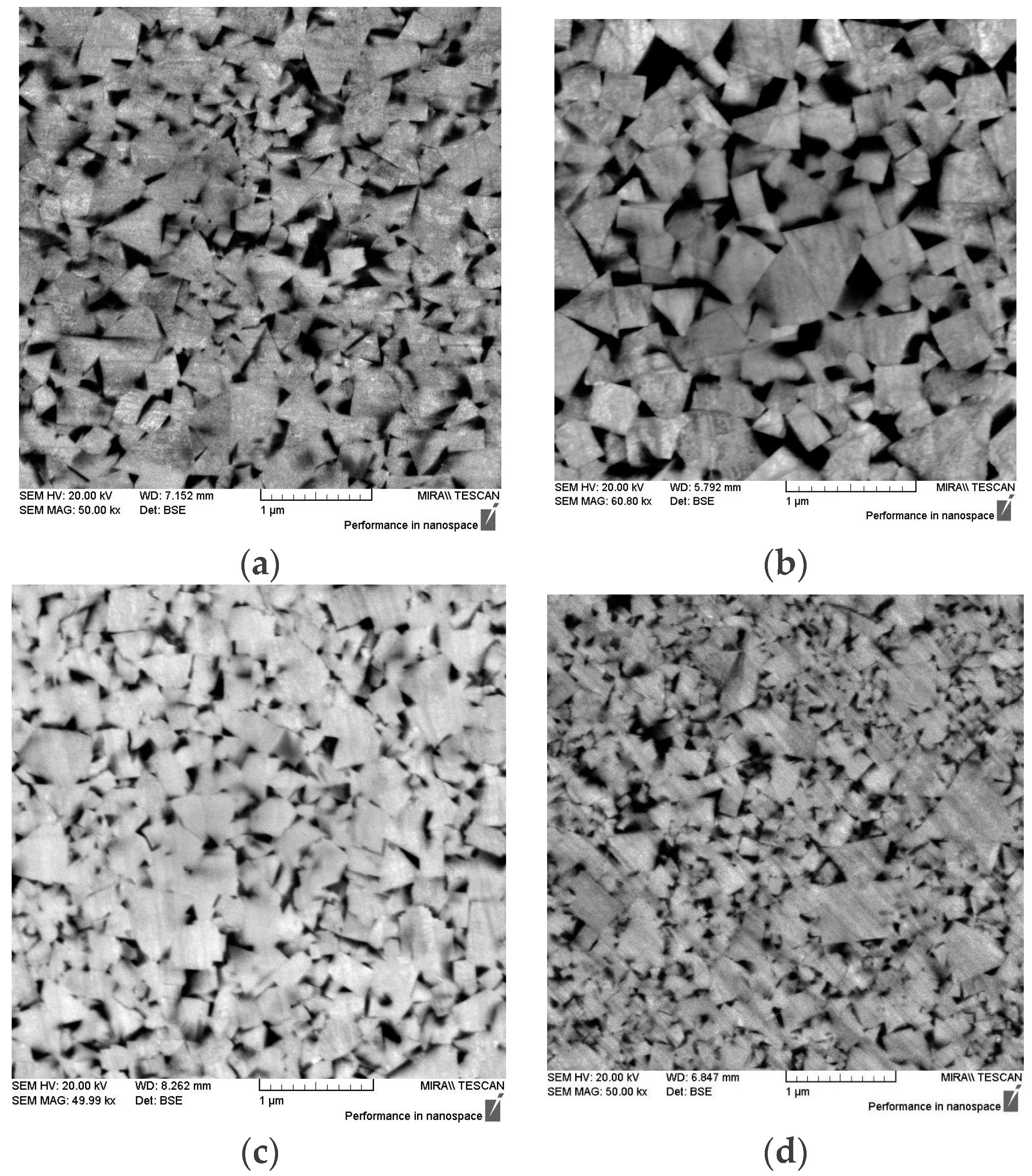
The microstructure of all of the samples is fine, with a uniform grain-size distribution, homogeneous, and without abnormal grain growth. The size of the starting powders is almost retained in the sintered product and some of the developed cemented carbides can be classified as nanostructured WC-Co cemented carbides (dWC < 200 nm) where dWC represents the mean WC grain size determined by the linear intercept method. The largest grain size of dWC = 0.251 was measured for sample WC9Co-2 (Figure 3b), where a discontinuous growth of single carbides exists in the microstructure [10]. The microstructure becomes coarser for the WC9Co-2 mixture with the addition of only 0.27% VC as grain growth inhibitor in the starting powder compared to mixtures with higher content of GGIs. The microstructure of the samples, obtained by FESEM, is presented in Figure 3.
The mechanical properties of consolidated samples are presented in Table 2.
The modulus of elasticity for cemented carbide is >650 kN/mm2 and is 2–3 times higher than steel. It increases linearly with decreasing binder content [20]. It can be seen from the Table 2 that the values of Er, obtained from the nanoindentation, are significantly lower compared to theoretical values. The reduced/effective elastic modulus takes into account the fact that elastic displacements occur in both of the specimens, with Young’s modulus E and Poisson’s ratio, and the indenter, with elastic constants Ei and νi [18]. Accordingly, Er values are too low to be used for the calculation of fracture toughness from radial-median models. A reduced modulus of elasticity Er was used for the calculation of the sample’s modulus of elasticity Es. The values of the sample’s modulus of elasticity Es, are presented in Table 2 and are used for the calculation of the fracture toughness. According to the literature the values of Poisson’s ratio and modulus of elasticity were used as follows: νi = 0.075, νs = 0.23, Ei = 890 GPa [6,23,24,25]. Indentation values of the reduced elastic modulus Er were calculated on the basis of five measurements obtained by applying the test force Pmax of 8 mN using a Berkovich indenter and a maximum penetration depth of around 100 nm for each sample. The calculated values of Es are in the range from 544.4 to 609.9 GPa and correspond to the theoretical values of the modulus of elasticity of the cemented carbides. Er is approximately 200 GPa lower compared to Es for WC9Co and WC6Co samples. The difference between Er and Es values is increasing with a decreasing Co content. For the WC4Co sample the difference amounts 235 GPa. The reduced modulus of elasticity Er was determined as an arithmetic mean of five indentations for each consolidated sample. Load-displacement curves for sample SV 1-1 are presented in Figure 4.
The scatter in the measured results can be attributed to the response of the individual phases; the indents with higher penetration depth belong to the area with more Co phase, while lower penetration depth belongs to the area with WC grains. Additionally, the reason for scattering can be attributed to the residual stresses and dislocation networks in WC grains developed in the surface and subsurface zone during the preparation of the sample surface (grinding/polishing) [12]. It has been found that the macroscopic residual stresses that are induced by grinding of the sample surface play a strong role and can overshadow the influence of crystallographic orientation of WC grains on the measured hardness and elastic modulus [12]. Hegeman et al. reported that compressive grinding residual stresses cause a deformed layer of approximately 1.5 µm consisting of fragmented and plastic deformed WC grains bonded by the remaining cobalt [26]. Additionally, it was found that the residual stresses can be significantly reduced by polishing and heat treatment from approx. 1500 to 200 MPa [26,27]. Accordingly, the specimens were polished down to 0.4 µm using diamond paste.
The residual stress from indentation is only a part of the residual stresses appearing in the vicinity of the sample due to the thermal expansion mismatch of the constituent phases [27]. In addition to macroscopic residual stresses, the thermal residual stresses or microscopic residual stresses occur in cemented carbides as a consequence of a difference in the coefficient of thermal expansion of WC crystals and the Co binder (∆α ≈ 6 × 10⁻⁶ K−1) during cooling from the sintering temperature [28].
Suresh et al. proposed a method for the estimation of residual stresses and residual plastic strains by instrumented sharp indentation in elastoplastic solids since it is assumed that the residual stress is uniform beneath the indented surface, which is at least several times larger than the indentation contact diameter [29]. The stress field generated by the indentation is heterogeneous and leads to plastic deformation and damage in the vicinity of the tip. Sergejev et al. used nanoindentation to determine the scope of the residual stresses in cemented carbides and cements. Residual stresses and fracture toughness by means of nanoindentation were not analysed within this research, but represent the extension of the research.
The modulus of elasticity values were essential for the calculation of fracture toughness by the Niihara, Morrena, and Hasselman model (NMH) for Palmqvist cracks and the Niihara, Morena, and Hasselman model, Antis, Chantikul, Lawn, and Marshall model, and Laugier model for radial-median cracks. The value of critical load Pc used for the calculation of Exner crack resistance is higher for the mixtures with higher Co content indicating better fracture toughness. Small cracks on the corners of the Vickers indentations occur with a force of 19.614 N, which corresponds to measuring method HV2 for WC-9% Co mixtures. For WC-6 wt. % Co and WC-4 wt. % Co mixtures the cracks occur at a force value of 9.807 N, which corresponds to measuring method HV1. Fracture toughness values calculated by different crack models are presented in Table 3. The values represent the mean of five indentations on each sample of consolidated near-nano and nanostructured cemented carbides.
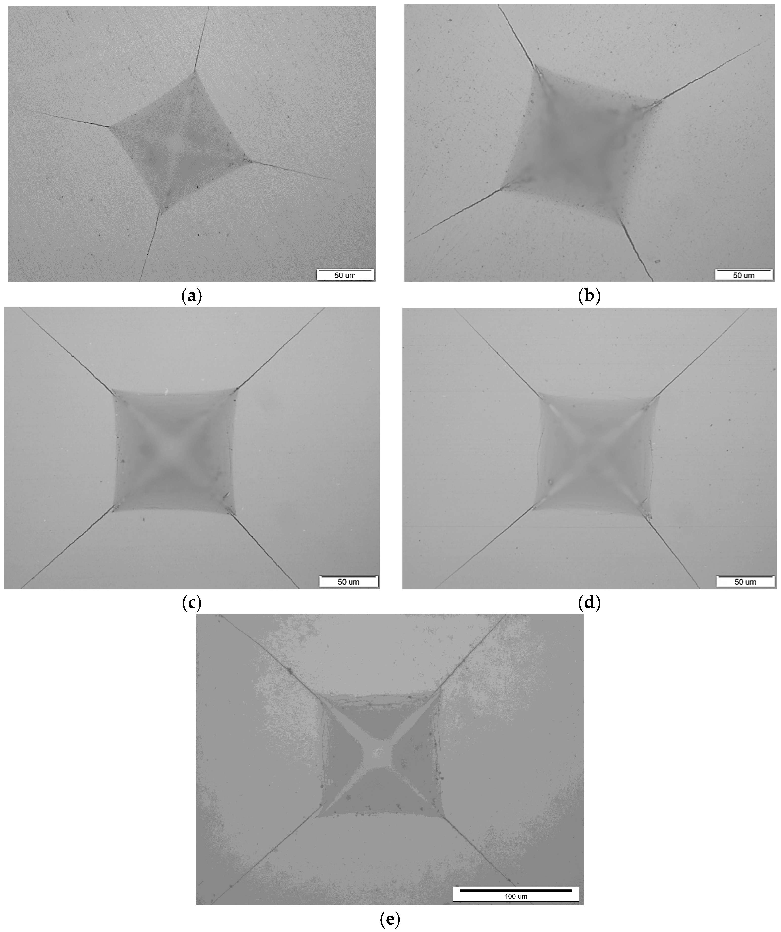
The highest values of KIc were calculated for WC-9 wt. % Co mixtures. Vickers indentations on each sample are presented in Figure 5.
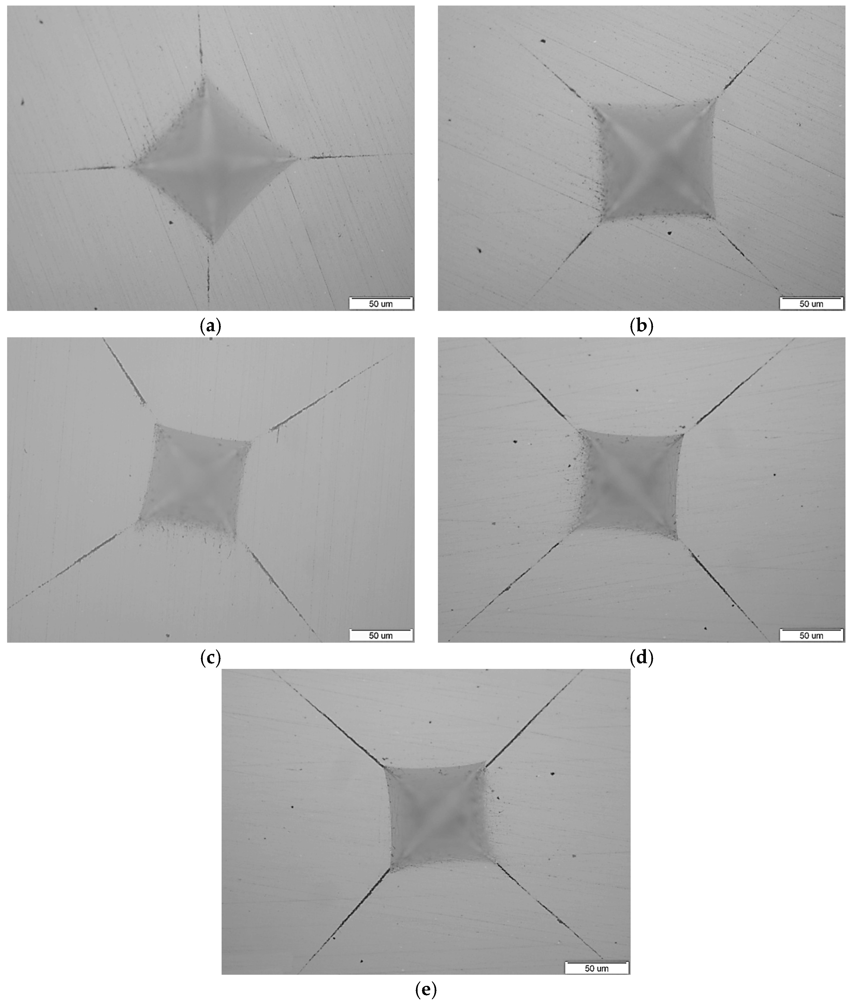
As can be seen in the figures of the indentations, the cracks on the indentation corners occur as a consequence of the applied load. There is no extensive lateral cracking or spalling around the indentations. The surrounding area of Vickers indentations is free of multiple cracking and the crack length could be easily measured. Vickers indentations on each sample after repolishing are presented in Figure 6.
As can be seen in the figures, the cracks did not remain connected to the tips of the Vickers indentations for WC-9 wt. % Co and WC-6 wt. % Co (Figure 5a–d), which is not the case for the WC-4 wt. % Co sample (Figure 5e). The cracks are not detached from the tips of the Vickers indentations for the WC4Co sample, which is characteristic of radial-median cracks. Accordingly, it can be concluded that near-nano and nanostructured cemented carbides with 9 wt. % Co and 6 wt. % Co do not exhibit median cracking and the indenter cracks remain radial in nature, while near-nano and nanostructured cemented carbides with 4 wt. % Co exhibit both radial and median cracking. The critical amount of the binder phase in near-nano and nanostructured WC-Co at which the crack changes its geometry from Palmqvist to radial-median is around 4 wt. % Co.
4. Analysis and Discussion
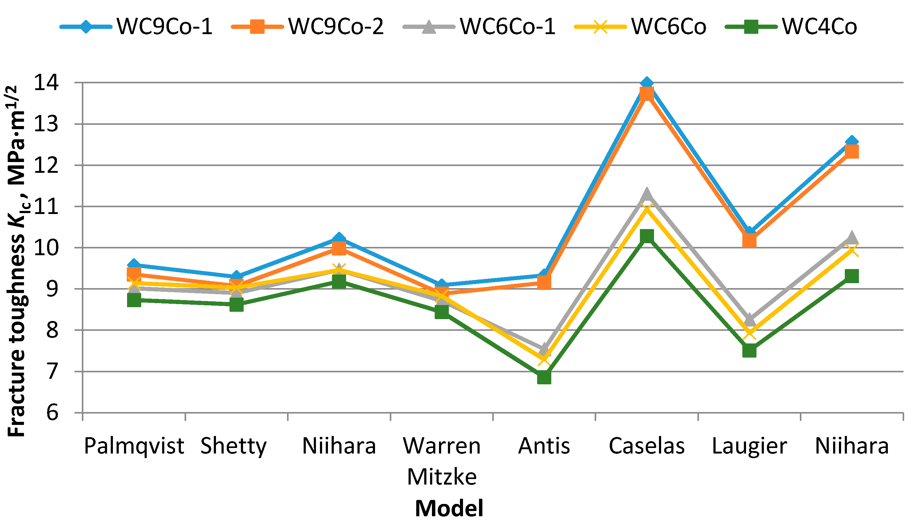
Measured Palmqvist toughness values correspond to already-published research [19]. Fang reported KIc values in the range from 8.8 to 9.5 MPa·m1/2 for the hardness range from 1887 to 2084 HV [1]. The highest WK values were measured for the WC9Co mixture, while the lowest WK values were measured for the WC4Co mixture, which indicates that highest values are achieved for the mixtures with greater amounts of GGIs and smaller WC grain size. Slightly decreased WK values were noted for the WC9Co mixture with the same amount of Co binder, but different GGIs. The mentioned decrease is very small and can be explained as a measuring error. Still, GGIs influencing the Palmqvist toughness behaviour of near-nano and nanostructured cemented carbides should not be excluded/ignored. Comparing WK values of WC6Co mixtures, it can be seen that slightly higher values are measured for sample SV 4-1 having higher amounts of GGIs and smaller WC grain size. Additionally, the influence of Co content on the Palmqvist toughness is noted; WK decreases with the decreasing Co content, which is the characteristic behaviour of cemented carbides. Cuadrado et al. reported the fracture toughness of WC grains at different orientations evaluated by nanoindentation in the range from 7.2 ± 2.4 to 8.7 ± 1.1 MPa·m1/2 [10]. The values are lower compared to the measured Palmqvist toughness values, which can be explained by significantly higher values of the applied load, meaning that the affected area of the indent consists of the WC grains and Co binder. The Co binder is a tougher phase compared to the WC crystals and, accordingly, is characterised by higher fracture toughness values. A graphical presentation of the calculated KIc for all models is presented in Figure 7.
As can be seen in Figure 7, KIc values calculated for the different models are not consistent and notably differ. Smaller deviations in KIc values are calculated for the models from Exner crack resistance for the Palmqvist crack. The closest values to WK are calculated by applying the SWMC crack model, known as Shetty, to all samples. The difference between the Palmqvist toughness and the SWMC fracture toughness is as low as 3% for WC-9 wt. % Co samples, while for WC-6 wt. % Co and WC-4 wt. % Co samples are almost the same. The values determined by the Warren and Matzke (WM) model do not differ much from the Palmqvist and SWMC values, but are lower. The reason for such a good agreement of WM-SWMC and WM models is due to the same physical ideas of the two-dimensional trough-crack along the surface and spherical expansion of the stress field [14]. Additionally, the SWMC crack model was made on the basis of the WM model, but avoids the need for an asymptotic calculation and makes a minimum number of assumptions based on experimental observations of geometric cracks. The equation for the SWMC model includes the dimensionless factor of 0.0889, which is derived from the geometry of the Vickers indent and Poisson’s ratio of cemented carbides instead of being determined from the experiments [14]. The KIc deviation is decreased with a lowering of the Co content. The largest deviation between KIc and WK was calculated by the Niihara, Morrena, and Hasselman (NMH) model, which could be explained by different origins of the crack. The NMH model is developed for the realistic length of a crack (0.25 ≤ L/a ≤ 2.5), while WM is built on the asymptotic approximation of very long cracks (L > a) [14]. The same trend was noted for all samples.
Larger KIc deviations were calculated by equations concerning radial-median crack models. The calculated KIc varies in the range from 9.15 to 13.99 MPa·m1/2 and significantly differs for each equation used. Significantly lower KIc values were calculated by the Laugier and Antis model compared to the Casellas and Niihara models. The lowest KIc values were calculated by the Antis model, while the highest was calculated by the Casellas model. Here it is also noted that the deviation of the calculated KIc is decreased with a lowering of the Co content. The lowest KIc values were calculated for the WC4Co mixture while the highest KIc values were calculated for WC9Co-1, which confirms the conclusions adopted by the Palmqvist crack models regarding the influence of GGIs and WC grain size on the KIc. The highest values were achieved for the mixtures with higher Co content, higher amount of GGIs, and smaller WC grain size.
The radial-median crack models assume a relatively high ratio of the crack length to the half diagonal of the indentation C/a ≥ 3. Additionally, all of these models incorporate the modulus of elasticity, which is not the case for the Palmqvist crack models. The specified model suggests that the precise values of the elastic modulus are desired for use in the radial-median crack models determined by conventional techniques. Even though the values of Es, determined by nanoindentation, correspond to the theoretical values for WC-Co cemented carbides for the purpose of making final conclusions, it is necessary to carry out a determination of E by tension or compressive tests.
The reason for such a large KIc deviation calculated by the radial-median crack models can also be related to the fact that the equations are the products of dimensional analyses modified with the experimentally-derived calibration factors, or represent the manipulation of previous equations with new calibration constants in an attempt to achieve reasonably correct values for the material under investigation [8]. Accordingly, the radial-median crack models are not recommended for the measurement of fracture toughness of near-nano and nanostructured cemented carbides even for samples which exhibit radial-median cracking, which was the case for the WC-4Co mixture examined in the paper.
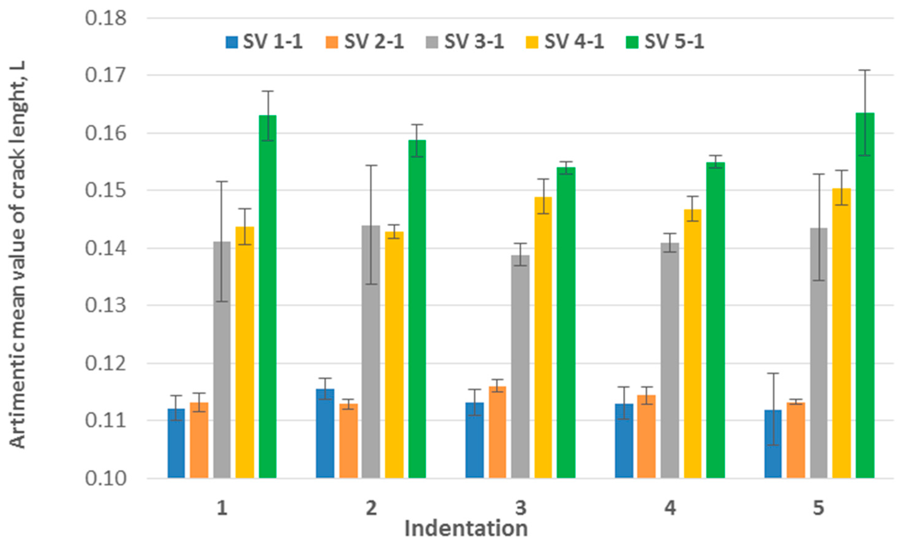
The crack growth in diverse directions was analysed and graphically presented in Figure 8.
It can be seen from Figure 8 that the crack propagation in diverse directions differs from indentation to indentation. In particular indentations the difference between the measured crack lengths in diverse directions is very small and the cracks are spread uniformly in all directions. In some indentations the situation is quite the opposite; cracks are spread unevenly in diverse directions. The smallest standard deviations of the crack length was determined for the sample SV 2-2 with the lowest content of GGIs, while the largest standard deviations of the measured crack lengths were obtained for sample SV 3-2. The average relative deviation (the difference between maximal and minimal crack length divided with the average crack length for each indentation) is the lowest for sample SV 2-2 and amounts to 4.31%, while the largest average relative deviation was determined for sample SV 3-2 and amounts to 18.6%. There are many reasons which can be attributed to such a behaviour. The first one is the difference in the properties of the constituent phases and anisotropy of the WC crystals already discussed in the nanoindentation section. The second one are residual stresses. It was found that the residual stresses determined by nanoindentation are lower compared to residual stresses determined by higher loads HV10, HV30, and HV50, which can be explained by the material response to indentation. With the increases of the indentation load, the response of the material increases and leads to larger amounts of the residual stresses to resist the indentation [27]. Additionally, the residual stresses measured for each phase showed the difference in magnitude and stress type. Larson et al. found that in-plane compressive stresses in WC crystals are in the range from −300 to −500 MPa, while the stresses in the Co phase are in the range from 400 to 700 MPa [28].
In order to get better insight in the fracture toughness of nanostructured hard metals, the techniques based on the pre-cracked samples, such as SEBN, SEVBN, and SCF methods, are planned for future research. According to literature, the KIc values of fracture toughness obtained by VIF techniques are higher than those determined by conventional pre-cracked methods [30,31]. The reason for the difference can be explained by the fact that the toughness values determined by SENB and SCF methods are strongly dependent upon residual stresses induced during the corresponding pre-cracking procedure [31]. It can be assumed that KIc would be lower compared to WK values obtained from this research. The research of complex residual stresses which occur around the surrounding area of Vickers indentations as a consequence of macroscopic compressive residual stresses and thermal residual stresses is planned for future research.
5. Conclusions
The following conclusions can be drawn from the conducted research:
- (i)
- Near-nano and nanostructured cemented carbides with 6 wt. % Co and 9 wt. % Co do not exhibit median cracking and the indenter cracks remain radial in nature, while near-nano and nanostructured cemented carbides with 4 wt. % Co exhibit both radial and median cracking. The critical amount of the binder phase in near-nano and nanostructured WC-Co at which the crack changes its geometry from Palmqvist to radial-median is around 4 wt. % Co.
- (ii)
- Comparing different models for the KIc calculation, it was found that the values are not consistent and differ for each method used. The Palmqvist crack models showed to be more applicable to near-nano and nanostructured cemented carbides even for the WC4Co sample, which exhibited radial-median cracking.
- (iii)
- KIc values calculated by models from the Exner crack resistance for the Palmqvist crack are in good agreement. The best compatibility was found for Palmqvist toughness and the SWMC model (Shetty).
- (iv)
- Radial-median crack models were found inappropriate to describe cracking in near-nano and nanostructured cemented carbides due to large KIc deviations for the same testing conditions, even for WC4Co, which exhibited radial-median cracking. The difference in KIc values is decreased with lowering Co content for both types of cracks and all crack models.
- (v)
- The crack propagation in diverse directions differs from indentation to indentation, which can be attributed to residual stresses, differences in properties of the constituent phases, and anisotropy of WC crystals.
Author Contributions
Tamara Aleksandrov Fabijanić performed the characterization of cemented carbides, measurements of fracture toughness, and wrote the paper; Danko Ćorić analyzed the data; Mateja Šnajdar Musa performed nanoindentation measurements; and Matija Sakoman performed analysis of crack type.
Conflicts of Interest
The authors declare no conflict of interest.
References
- Fang, Z.Z.; Wang, X.; Ryu, T.; Hwang, K.S.; Sohn, H.Y. Synthesis, sintering, and mechanical properties of nanocrystalline cemented tungsten carbide—A review. Int. J. Refract. Met. Hard Mater. 2009, 27, 288–299. [Google Scholar] [CrossRef]
- Bonache, V.; Salvador, M.D.; Busquets, D.; Burguete, P.; Martinez, E.; Sapina, F.; Sanchez, E. Synthesis and processing of nanocrystalline tungsten carbide: Toward cemented carbides with optimal mechanical properties. Int. J. Refract. Met. Hard Mater. 2011, 29, 78–84. [Google Scholar] [CrossRef]
- Fabijanić, T.A.; Alar, Ž.; Ćorić, D. Influence of consolidation process and sintering temperature on microstructure and mechanical properties of near-nano and nanostructured WC-Co Cemented Carbides. Int. J. Refract. Met. Hard Mater. 2015, 54, 82–89. [Google Scholar] [CrossRef]
- International Standard Organisation. ISO 28079:2009: Hardmetals-Palmqvist Toughness Test. Available online: https://www.iso.org/obp/ui/#iso:std:iso:28079:ed-1:v1:en (accessed on 18 April 2017).
- Roebuck, B.; Bennett, E.G. Hardmetal Toughness Tests: VAMAS Interlaboratory Exercise; NPL Report MATC: Teddington, UK, 2005. [Google Scholar]
- Sergejev, F.; Antonov, M. Comparative study on indentation fracture toughness measurements on cemented carbides. Proc. Estonian Acad. Sci. Eng. 2006, 12, 388–398. [Google Scholar]
- Sheikh, S.; M’Saoubi, R.; Flasar, P.; Schwind, M.; Persson, T.; Yang, J.; Llanes, L. Fracture toughness of cemented carbides: Testing method and microstructural effect. Int. J. Refract. Met. Hard Mater. 2015, 49, 153–160. [Google Scholar] [CrossRef]
- Shetty, D.K.; Wright, I.G.; Mincer, P.N.; Clauer, A.H. Indentation fracture toughness of WC-Co cermets. J. Mater. Sci. 1985, 20, 1873–1882. [Google Scholar] [CrossRef]
- Quinn, G.D.; Brant, R.D. On the vickers indentation fracture test. J. Am. Ceram. Soc. 2007, 90, 673–680. [Google Scholar] [CrossRef]
- Cuadrado, N.; Casellas, D.; Llanes, L.; Caro, J. Effects of crystal anisotropy on the mechanical properties of WC embedded in WC-Co cemented carbides. In Proceedings of the Euro PM2011—Hard Materials, Barcelona, Spain, 9–12 October 2011. [Google Scholar]
- Sebastiani, M.; Johanns, K.E.; Herbert, E.G.; Pharr, G.M. Measurement of fracture toughness by nanoindentation methods: Recent advances and future challenges. Curr. Opin. Solid State Mater. Sci. 2015, 19, 324–333. [Google Scholar] [CrossRef]
- Duszováa, A.; Halgaša, R.; Bľandaa, M.; Hvizdoša, P.; Lofaja, F.; Duszaa, J.; Morgield, J. Nanoindentation of WC–Co hardmetals. J. Eur. Ceram. Soc. 2013, 33, 2227–2232. [Google Scholar] [CrossRef]
- Gee, M.G.; Roebuck, B.; Lindahl, P.; Andren, H.-O. Constituent phase nanoindentation of WC/Co and Ti(C,N) hard metals. Mater. Sci. Eng. A 1996, 209, 128–136. [Google Scholar] [CrossRef]
- Bonache, V.; Rayón, E.; Salvador, M.D.; Busquets, D. Nanoindentation study of WC–12Co hardmetals obtained from nanocrystalline powders: Evaluation of hardness and modulus on individual phases. Mater. Sci. Eng. A 2010, 527, 2935–2941. [Google Scholar] [CrossRef]
- Shatov, A.V.; Ponomarev, S.S.; Firstov, S.A. Fracture and strength of hardmetals at room temperature. Compr. Hard Mater. 2014, 1, 301–343. [Google Scholar]
- Aleksandrov Fabijanić, T.; Jakovljević, S.; Franz, M.; Jeren, I. Influence of grain growth inhibitors and powder size on the properties of ultrafine and nanostructured cemented carbides sintered in hydrogen. Metals 2016, 6, 198. [Google Scholar] [CrossRef]
- Barsoum, M.W. Series in Material Science and Engineering Fundamentals of Ceramics; Taylor & Francis: Abingdon, UK, 2003. [Google Scholar]
- Oliver, W.C.; Pharr, G.M. Measurement of hardness and elastic modulus by instrumented indentation: Advances in understanding and refinements to methodology. J. Mater. Res. 2004, 19, 3–20. [Google Scholar] [CrossRef]
- Ferreira, J.A.M.; Pina Amaral, M.A.; Antunes, F.V.; Costa, J.D.M. A study on the mechanical behaviour of WC/Co hardmetals. Int. J. Refract. Met. Hard Mater. 2008, 54, 82–89. [Google Scholar] [CrossRef]
- The Designer’s Guide to Tungsten Carbide. Available online: http://www.generalcarbide.com/assets/pdf/GCDesignerGuide.pdf (accessed on 15 July 2016).
- Šnajdar Musa, M.; Marić, G.; Grilec, K. Nanoindentation of closed cell Al alloy foams subjected to different heat treatment regimes. Compos. B 2016, 89, 383–387. [Google Scholar] [CrossRef]
- Malzbender, J.; den Toonder, J.M.J.; Balkenende, A.R.; de With, G. Measuring mechanical properties of coatings: A methodology applied to nano-particle-filled sol–gel coatings on glass. Mater. Sci. Eng. 2002, 36, 47–103. [Google Scholar] [CrossRef]
- Hess, P. The mechanical properties of various chemical vapor deposition diamond structures compared to the ideal single crystal. J. Appl. Phys. 2012, 111, 051101. [Google Scholar] [CrossRef]
- Wentorf, R.H.; DeVries, R.C.; Bundy, F.P. Sintered superhard materials. Science 1980, 208, 873–890. [Google Scholar] [CrossRef] [PubMed]
- Lin, J.D.; Duh, J.G. Fracture toughness and hardness of ceria and yttria-doped tetragonal zirconia ceramics. Mater. Chem. Phys. 2002, 78, 253–261. [Google Scholar] [CrossRef]
- Hegeman, J.B.J.; De Hosson, J.T.; de With, G. Grinding of WC–Co hardmetals. Wear 2001, 248, 187–196. [Google Scholar] [CrossRef]
- Sergejev, F.; Kimmari, E.; Viljus, M. Residual stresses in TiC-based cermets measured by indentation. Eng. Procedia 2011, 10, 2873–2881. [Google Scholar] [CrossRef]
- Larsson, C.; Ode’n, M. X-ray diffraction determination of residual stresses in functionally graded WC–Co composites. Int. J. Refract. Met. Hard Mater. 2004, 22, 177–184. [Google Scholar] [CrossRef]
- Suresh, S.; Giannnakopoulus, A.E. A new method for estimating residual stresses by instrumented sharp indentation. Acta Mater. 1998, 46, 5755–5767. [Google Scholar] [CrossRef]
- Stecker, K.; Ribero, S.; Hoffmann, M.-J. Fracture toughness measurement of LPS-SiC: A comparison of the indentation technique and the SEVNB method. Mater. Res. 2005, 8, 121–124. [Google Scholar] [CrossRef]
- Torres, Y.; Casellas, D.; Anglada, M.; Llanes, L. Fracture toughness evaluation of hardmetals: Influence of testing procedure. Int. J. Refract. Met. Hard Mater. 2001, 19, 27–34. [Google Scholar] [CrossRef]
Figure 1.
Load-displacement diagram with characteristics values [18].
Figure 1.
Load-displacement diagram with characteristics values [18].
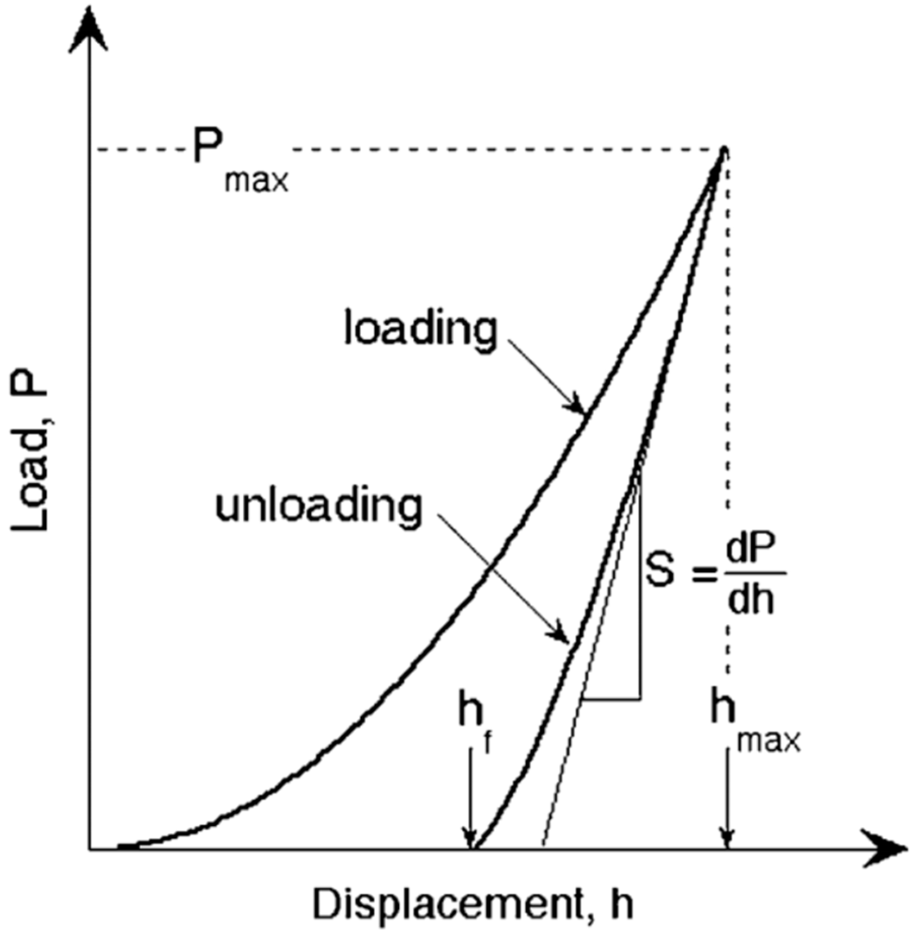
Figure 2.
Types of cracks in cemented carbides.
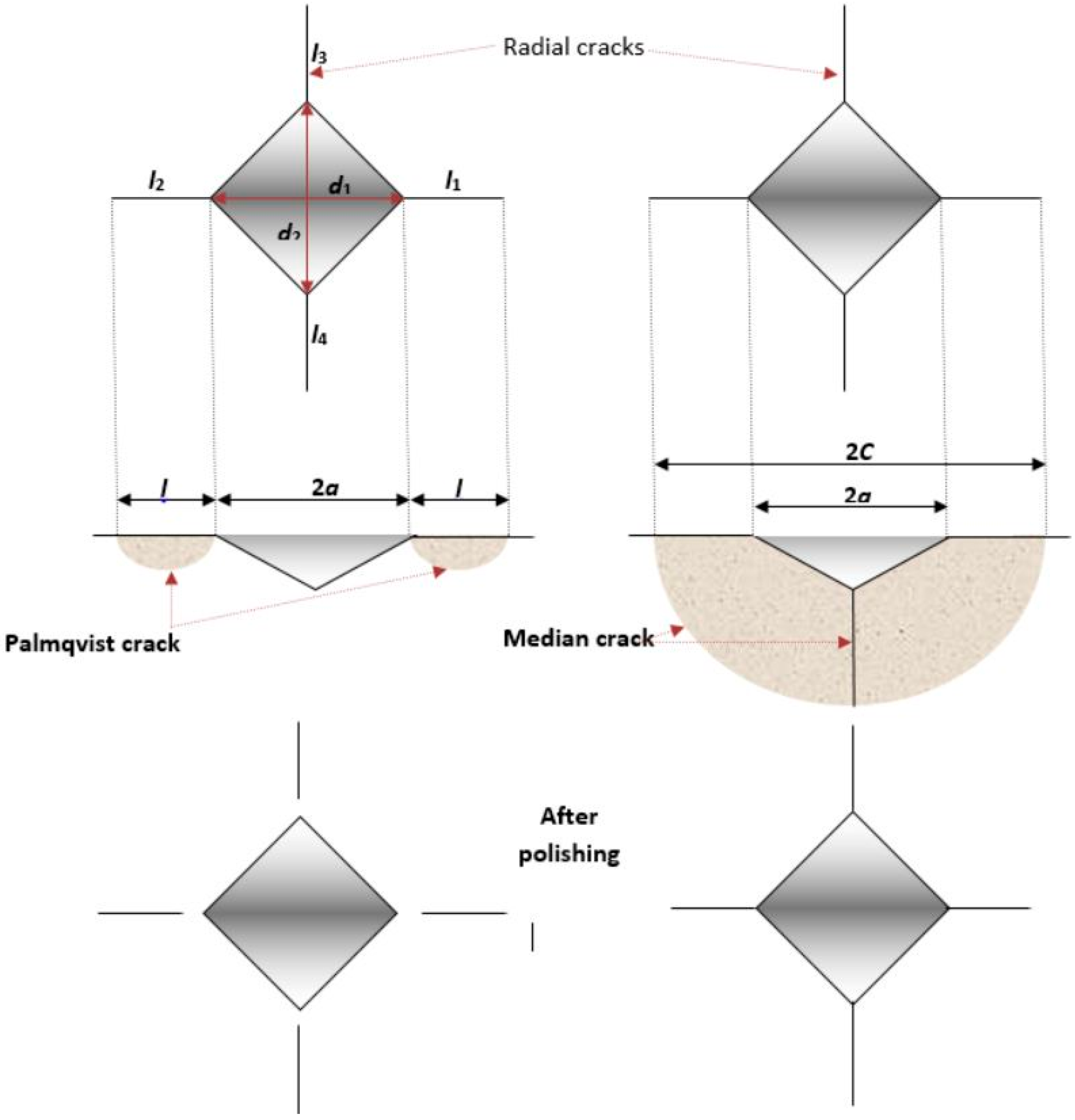
Figure 3.
Microstructure of samples: (a) SV 1-1; (b) SV 2-1; (c) SV 3-1; and (d) SV 4-1.

Figure 4.
Load-displacement curves for sample SV 1-1.

Figure 5.
Vickers indentation on consolidated samples: (a) SV 1-1; (b) SV 2-1; (c) SV 3-1; (d) SV 4-1; and (e) SV 5-1.
Figure 5.
Vickers indentation on consolidated samples: (a) SV 1-1; (b) SV 2-1; (c) SV 3-1; (d) SV 4-1; and (e) SV 5-1.

Figure 6.
Vickers indentation on consolidated samples after polishing: (a) SV 1-1; (b) SV 2-1; (c) SV 3-1; (d) SV 4-1; and (e) SV 5-1.
Figure 6.
Vickers indentation on consolidated samples after polishing: (a) SV 1-1; (b) SV 2-1; (c) SV 3-1; (d) SV 4-1; and (e) SV 5-1.

Figure 7.
Fracture toughness for all models used.

Figure 8.
Graphical presentation of crack length with standard deviation.

| Mixture | Powder | Grain Size dBET, nm | Specific Surface, m2/g | GGI, wt. % | Co, wt. % |
|---|---|---|---|---|---|
| WC9Co-1 | WC DN 2-5/1 | 150 | 2.57 | 0.26% VC, 0.45% Cr3C2 | 9 |
| WC9Co-2 | WC DN 2-5/2 | 150 | 2.59 | 0.27% VC | 9 |
| WC6Co-1 | WC DN 2-5/1 | 150 | 2.57 | 0.26% VC, 0.45% Cr3C2 | 6 |
| WC6Co | WC DN 4-0 | 95 | 3.92 | 0.41%VC, 0.80% Cr3C2 | 6 |
| WC4Co | WC DN 2-5/1 | 150 | 2.57 | 0.26% VC, 0.45% Cr3C2 | 4 |
Table 2.
The mechanical properties of samples.
| Mixture | Sample | HV 30 | Pc, N | W, N/mm | Er, GPa | νs | νi = νD | Ei = ED GPa | Es GPa |
|---|---|---|---|---|---|---|---|---|---|
| WC9Co-1 | SV 1-1 | 1879.3 | 19.614 | 606.8 | 358.6 | 0.227 | 0.075 | 890 | 566.7 |
| WC9Co-2 | SV 2-1 | 1809.4 | 19.614 | 602.6 | 350.0 | 0.227 | 544.4 | ||
| WC6Co-1 | SV 3-1 | 2041.1 | 9.807 | 502.1 | 362.7 | 0.222 | 577.6 | ||
| WC6Co | SV 4-1 | 2196.1 | 9.807 | 485.5 | 368.1 | 0.222 | 592.2 | ||
| WC4Co | SV 5-1 | 2140.1 | 9.807 | 448.1 | 374.5 | 0.220 | 609.9 |
Table 3.
Fracture toughness by different crack models.
| Mixture | Sample | Palmqvist Toughness, WK, MPa·m1/2 | Palmqvist Crack Model KIc, MPa·m1/2 | Radial-Median Crack Model KIc, MPa·m1/2 | |||||
|---|---|---|---|---|---|---|---|---|---|
| Shetty | Niihara | Warren Mitzke | Laugier | Antis | Caselas | Niihara | |||
| WC9Co-1 | SV 1-1 | 9.58 | 9.29 | 10.22 | 9.09 | 10.36 | 9.33 | 13.99 | 12.57 |
| WC9Co-2 | SV 2-1 | 9.35 | 9.07 | 9.98 | 8.88 | 10.17 | 9.15 | 13.73 | 12.33 |
| WC6Co-1 | SV 3-1 | 9.01 | 8.90 | 9.46 | 8.71 | 8.26 | 7.54 | 11.31 | 10.25 |
| WC6Co | SV 4-1 | 9.14 | 9.03 | 9.46 | 8.83 | 7.93 | 7.29 | 10.93 | 9.94 |
| WC4Co | SV 5-1 | 8.73 | 8.62 | 9.18 | 8.44 | 7.51 | 6.86 | 10.28 | 9.31 |
© 2017 by the authors. Licensee MDPI, Basel, Switzerland. This article is an open access article distributed under the terms and conditions of the Creative Commons Attribution (CC BY) license (http://creativecommons.org/licenses/by/4.0/).
Share and Cite
MDPI and ACS Style
Aleksandrov Fabijanić, T.; Ćorić, D.; Šnajdar Musa, M.; Sakoman, M. Vickers Indentation Fracture Toughness of Near-Nano and Nanostructured WC-Co Cemented Carbides. Metals 2017, 7, 143. https://doi.org/10.3390/met7040143
AMA Style
Aleksandrov Fabijanić T, Ćorić D, Šnajdar Musa M, Sakoman M. Vickers Indentation Fracture Toughness of Near-Nano and Nanostructured WC-Co Cemented Carbides. Metals. 2017; 7(4):143. https://doi.org/10.3390/met7040143
Chicago/Turabian StyleAleksandrov Fabijanić, Tamara, Danko Ćorić, Mateja Šnajdar Musa, and Matija Sakoman. 2017. "Vickers Indentation Fracture Toughness of Near-Nano and Nanostructured WC-Co Cemented Carbides" Metals 7, no. 4: 143. https://doi.org/10.3390/met7040143
Note that from the first issue of 2016, this journal uses article numbers instead of page numbers. See further details here.