Influence of Temperature-Dependent Properties of Aluminum Alloy on Evolution of Plastic Strain and Residual Stress during Quenching Process

1
State Key Laboratory of High Performance Complex Manufacturing, Central South University, Changsha 410083, China
2
School of Mechanical and Electrical Engineering, Central South University, Changsha 410083, China
*
Author to whom correspondence should be addressed.
Metals 2017, 7(6), 228; https://doi.org/10.3390/met7060228
Submission received: 31 March 2017
/
Revised: 12 June 2017
/
Accepted: 15 June 2017
/
Published: 21 June 2017
(This article belongs to the Special Issue Light Weight Alloys: Processing, Properties and Their Applications)
Abstract
:To lessen quenching residual stresses in aluminum alloy components, theory analysis, quenching experiments, and numerical simulation were applied to investigate the influence of temperature-dependent material properties on the evolution of plastic strain and stress in the forged 2A14 aluminum alloy components during quenching process. The results show that the thermal expansion coefficients, yield strengths, and elastic moduli played key roles in determining the magnitude of plastic strains. To produce a certain plastic strain, the temperature difference increased with decreasing temperature. It means that the cooling rates at high temperatures play an important role in determining residual stresses. Only reducing the cooling rate at low temperatures does not reduce residual stresses. An optimized quenching process can minimize the residual stresses and guarantee superior mechanical properties. In the quenching process, the cooling rates were low at temperatures above 450 °C and were high at temperatures below 400 °C.
1. Introduction
Heat-treatable aluminum alloys are widely used to fabricate forged components used in aerospace and aircraft industry for weight reduction. Solution quenching and aging treatments are applied to the aluminum alloy components to obtain high mechanical properties [1]. For this purpose, fast cooling rates are required to avoid or limit precipitation during the quenching process [2]. However, high cooling rates result in serious inhomogeneous deformations and lead to high residual stresses [3], which deteriorates the mechanical properties and dimensional stability [4,5], and also have important impact on fatigue properties [6,7,8]. Therefore, it is important to study how to control the residual stresses.
Residual stresses can be relieved by plastic deformation. For example, Koç et al. [9] found that compression and stretching processes could reduce the residual stress of 7050 forged blocks by more than 90%. However, this technique cannot be used for complicated cross-section components [10]. Many researchers employed vibration methods to release the residual stresses [11,12] and studied their mechanisms [13]. However, this technique is confined to large components since the high amplitude of vibration deforms the thinner or smaller components [5]. Heat treatment methods are also applied to relieve the residual stresses. Dong et al. [10] successfully lowered the residual stress with uphill quenching and thermal-cold cycling processes. Sun et al. [14] relieved the residual stress by repeated heating of the samples at high heating rates and subsequent artificial aging treatment.
Although the technologies described above are effective in relieving the residual stresses, the need of special tools and procedures increases their costs. Therefore, an economical approach is to minimize the residual stresses during quenching. Residual stresses decrease with reducing cooling rates. Our previous work showed that, as compared to the mechanical properties, the residual stress decreased faster with decreasing cooling rates [15]. Dong et al. [10] balanced the residual stress and mechanical properties of the thin aluminum alloy plates with warm water at 80 °C. The mechanical performances are mainly determined by the cooling rates in the quenching sensitivity temperature range. The quenching sensitivity can be studied by time-temperature- transformation/properties (TTT/TTP) curves. For example, by using of TTP curves, Li et al. [16] showed that the mechanical performances of the 6063 aluminum alloy are determined by the cooling rates during the quenching sensitivity temperature range from 410–300 °C. Based on the results, they proposed a step quenching method to balance the mechanical properties and residual stresses. Its cooling rates are high in the quenching sensitivity temperature range to guarantee mechanical performances, and they are low in the others ranges to reduce residual stresses. Our previous work [15] showed that such a step quenching method could balance the residual stress and mechanical performances. However, the step quenching technology is mainly designed based on the characteristics of the quench-induced phase transformation of the material. It is best to utilize the characteristics of quenching residual stress evolution and quench-induced phase transformation during quenching to design the quenching technology. Nallathambi et al. [17] studied the influence of thermal, metallurgical, and mechanical properties on the final distortion and residual stresses during quenching. However, the effect of material properties on the evolution of residual stress at different temperatures is still unclear. This information is needed to guide the designing of quenching technology.
This work investigated the effect of temperature-dependent material properties of forged 2A14 aluminum alloy on the evolution of stress and plastic strain during quenching process using a constructed model and numerical simulation methods. Moreover, the effect of cooling rates on residual stresses was studied by quenching the samples with different quenching technologies. Table 1 listed all the nomenclatures used in this paper.
2. Methods
2.1. Theoretical Analysis
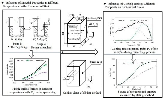
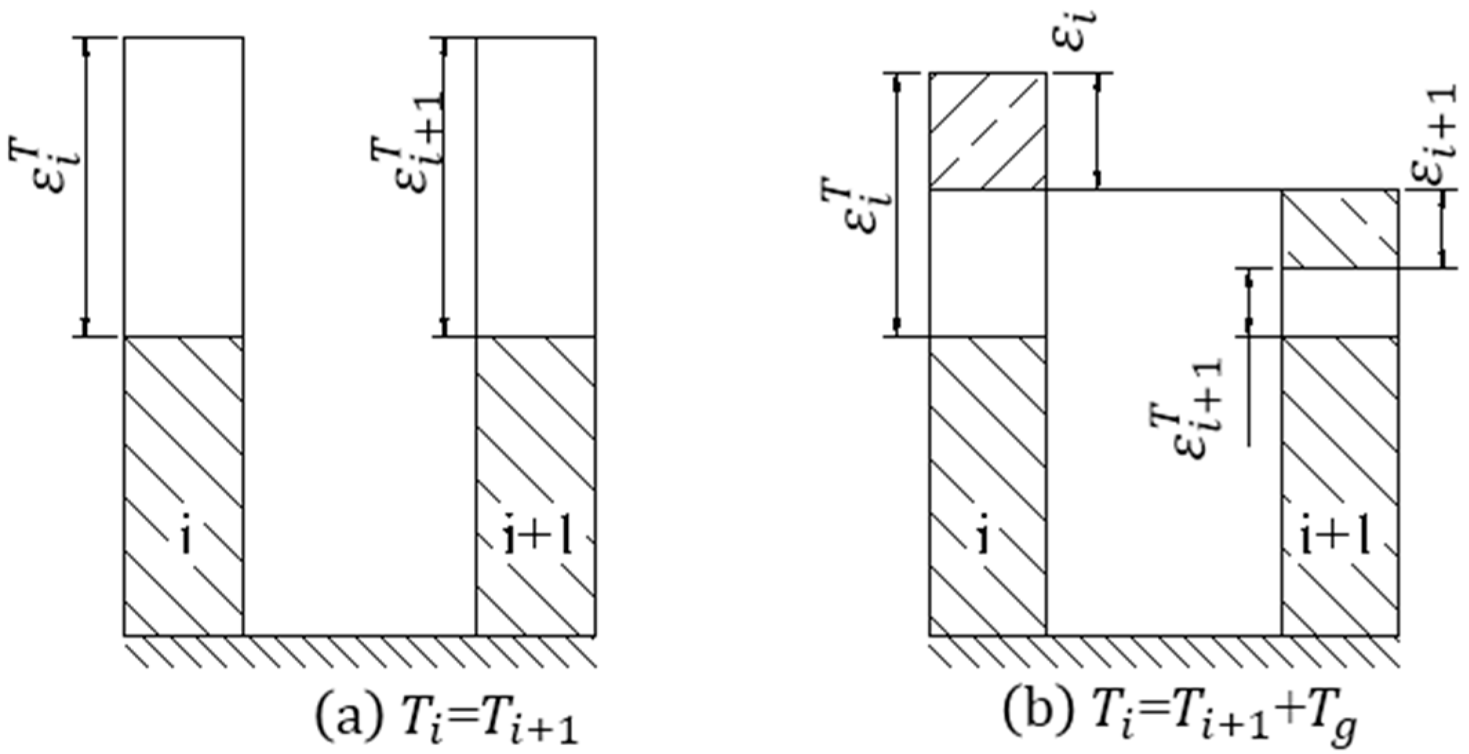
Residual stresses are determined by inhomogeneous plastic strains. They usually increase with increasing magnitude of plastic strain. During quenching, inhomogeneous temperature distribution causes inhomogeneous thermal expansion strain (), which causes the thermal stresses and strains to maintain the force and shape balance. When thermal stress exceeds the yield strength, plastic strain occurs. Material properties change with temperatures. The yield strengths and elastic moduli of 2A14 aluminum alloy decrease with increasing temperatures. This implies that the characteristics of evolution of thermal stresses and plastic strains may be different at different temperatures during quenching. In this work, a model with two units was proposed to investigate these characteristics (Figure 1). As shown in Figure 1a, the temperatures of the two units are initially the same, leading to the same thermal expansions. The thermal expansion was obtained using Equation (1), where 0 °C was taken as the reference temperature. As quenching proceeded, a temperature difference (Tg) between the two units appeared, as shown in Figure 1b; it resulted in strains to balance the unequal thermal expansions. To simplify the analysis, we presumed that the final heights of the two units are the same (Equation (2)). Moreover, the two units have the same magnitude of thermal stresses. The strain comprises elastic strain and plastic strain, which are described by Equation (4) in reference [18]. In this model, we presumed that the thermal stress always exceeds the yield strength (Equation (3)). Combining Equations (1)–(4), the plastic strain of unit i is obtained from Equation (5). Equations (6)–(8) proposed three variants, A, B, and C, to simplify the formation of Equation (5). Equation (9) was obtained by combining Equations (5)–(8), and was used to investigate the influence of temperature-dependent material properties on plastic strains at different temperatures, but with the same temperature difference. As shown in Table 2, the plastic moduli were obtained from a previous work [19]. The other material properties are described in Section 2.3.
where α, E, Ep, and σ0.2 are the thermal expansion coefficient, elastic modulus, plastic modulus, and yield strength, respectively. T is the temperature of the unit. ∆T is the temperature difference between T and reference 0 °C. εT, ε, εe, εp, and σ are the thermal expansion, total strain, elastic strain, plastic strain, and thermal stress, respectively. The subscript i is the number of the unit.
2.2. Quenching Experiment: Material and Heat Treatment
Quenching residual stresses are affected by products’ material properties, structure and inhomogeneous temperature distribution during quenching. The temperature distribution is determined by the cooling rates; increasing cooling rate increases the temperature gradient. The influence of cooling rates on residual stress was investigated by quenching the forged 2A14 aluminum alloy samples with different quenching technologies. The samples were machined from a commercial forged component 78 mm in thickness; their chemical compositions are listed in Table 3. As shown in Figure 2a, the size of the samples is 110 mm × 100 mm × 70 mm, and its thickness direction is along the z-axis. Their x, y, and z directions are along the long transverse direction, short transverse direction, and thickness direction of the component, respectively. Similar to our previous work [15], the two end surfaces (110 mm × 100 mm) were taken as the main heat-dispersing surfaces, while the other four surfaces were encapsulated with about 20-mm-thick asbestos. As shown in Table 4, the samples were quenched immediately after the solution treatment at 500 °C for 4 h. Sample A1 was quenched with room temperature water (about 20 °C). Sample A2 was first quenched in room temperature water until the temperature at the central point P0 decreased to about 410 °C, and then it was cooled in room temperature air. The transfer time was smaller than 1 s. Sample A3 was quenched by a step quenching technology using a spray-quenching device designed by us, as shown in Figure 3. Detailed information of the device is present in our submitted patent (CN 201710016344.5). As shown in Figure 2a, the temperatures at points P0 and P1 during quenching were monitored by using Φ1 mm naked type K thermocouples deeply embedded into the samples. The cooling history of P0 was used to stand for the cooling rates of the samples with different quenching technologies. The temperature difference between points P0 and P1 was used to estimate the inhomogeneous temperature distribution of the samples.
Refering to References [10,20], the residual stresses of the as-quenched samples were measured by the slitting method. As shown in Figure 2b, a wire-electrode cutting machine was used to cut incrementally along the cutting plane. With the incremental increase in the depth (aj) of the cutting plane, the residual stresses of the blocks were released. The strains (εy) in the y direction were measured by using foil strain gauges (BX120-5AA) with 5 mm gauge lengths, which were connected in 1/4 bridging mode. The central line of the gauge was at the mid-length of the sample. The strains were the functions of cutting depths (aj). We presumed that the residual stress σy(z) along the cutting plane is the function of z. As in Equation (10), it can be described by the polynomial Pi (70 − z) and the undetermined coefficient Ai. At the same time, as in Equation (11), the measured stains (εy) at different depths (aj) can be described by the undetermined coefficient Ai and compliance function Ci (aj). Ci (aj) is the strain at the measured point with the depth (aj) of the cutting plane increasing incrementally, when Pi (70 − z) stress was applied along the z direction of the sample. The numerical simulation method was used to calculate Ci (aj). As shown in Equation (12), the least square method is used to obtain Ai using the measured strains and calculated strains given in Equation (11). In this paper, the residual stress (Equation (10)) was not calculated, and, instead, the measured strains were used to estimate the residual stress of the samples, which underwent different quenching treatments.
The tensile test samples in x direction were machined from the mid-thickness part of the aged samples, and were used to evaluate the mechanical properties. Three test specimens were taken from every sample with dimensions of 2 × 8 mm2 and a gauge length 30 mm, utilizing a 25 mm gauge length extensometer according to GB/T 1685-2013. The samples were tested at a strain rate of 0.0011 s−1.
2.3. Numerical Simulation
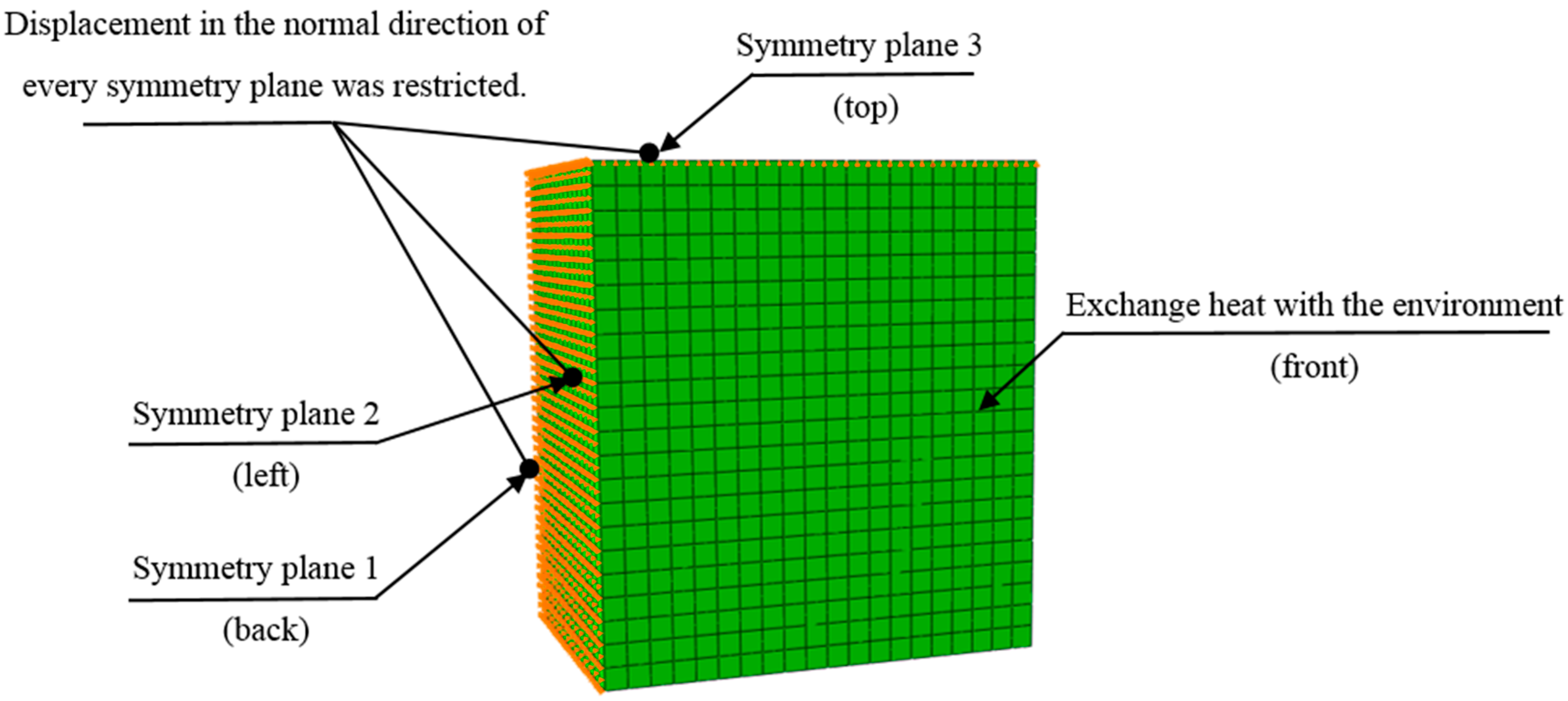
The numerical simulation software ABAQUS standard with coupled temperature–displacement analysis was used to further study the influence of material properties and cooling rates at different temperatures on plastic strain and residual stress during quenching. The size of the model was the same as that of the samples used for the heat treatment experiments. Only the two end surfaces (110 mm × 100 mm) exchanged heat with water during quenching. Due to the symmetry, only an eighth of the sample was used to reduce calculating time, as shown in Figure 4. The displacement in the normal direction of the three symmetry planes was restricted. Similar to the experiments, only end surface of this model exchanged heat with the environment. The element type used in this model is an 8-node thermally coupled brick, trilinear displacement and temperature element (C3D8T), and the number of the elements was 6160. The incremental time in the analysis is chosen automatically by the computer program and the solution technique is full Newton method.
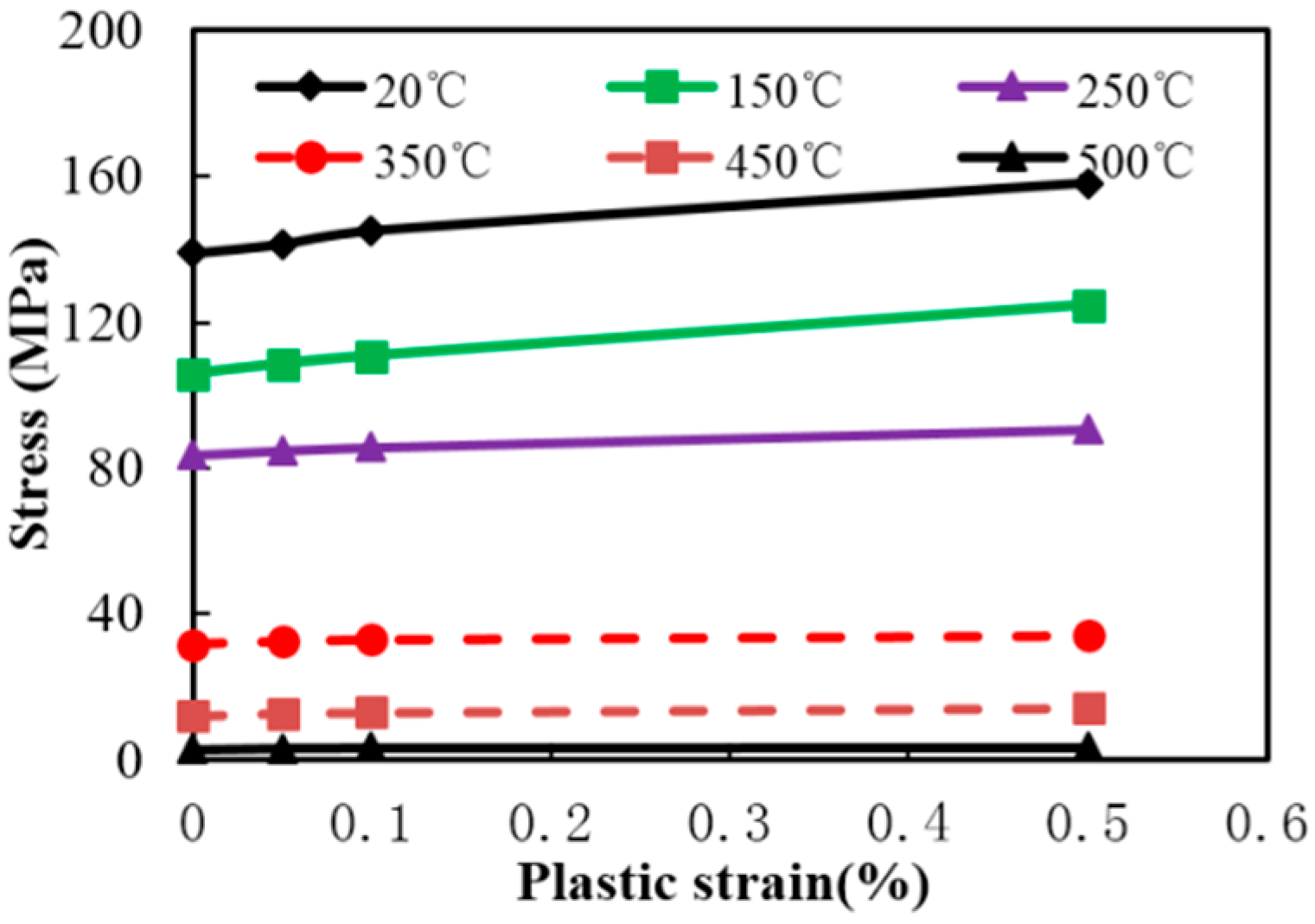
The density of this material is set constant at a value of 2800 kg·m−3. Figure 5 shows the yield stress at different plastic strains used in the simulation model, where the yield points at different temperatures are the small value of the curves. As shown in Table 5, the thermal expansion coefficients, elasticity moduli, conductivities, and specific heat capacities were obtained from the literature [21,22]. The convective heat transfer coefficient of aluminum/air was set constant at 0.2 kW·m−2·s−1.
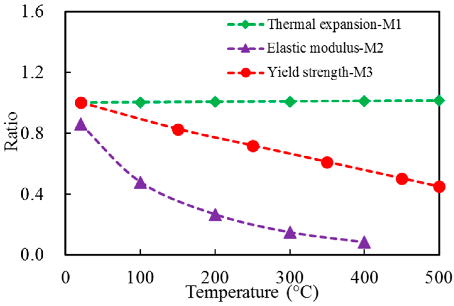
The temperature-dependent material properties changed with temperature, and affected the evolution of thermal stress and plastic strain at different temperatures during the quenching process. The thermal expansion coefficient, elastic modulus, and yield strength play key roles in the evolution of thermal stress and plastic strain. Numerical simulation was used to analyze the effect by comparing the properties of samples M0–M3 with different material properties, as shown in Table 6. Sample M0 used the measured material properties of the studied material, as shown in Table 5 and Figure 5. For samples M1–M3, only one kind of measured material properties was adjusted and they are the thermal expansion coefficient, elastic modulus, and yield strength, respectively. The material properties were adjusted by taking the value of the corresponding material properties at 20 °C as reference values, and multiplying the reference values with the multiplier factors at different temperatures (as shown in Figure 6) to obtain the corresponding values at different temperatures. The Mises stress and equivalent plastic strain (PEEQ) along the central line (L0) were used to estimate the level of residual stresses and plastic strains of the samples.
ABAQUS was also used to study the influence of cooling rates on the residual stresses by simulating the quenching process. Prior to this, the heat transfer coefficients of aluminum/water were obtained by using the Deform 2D inverse heat transfer module. The measured temperature vs. time curves at point P0 were used. The Mises stresses, principal stresses in the y direction (S22), equivalent plastic strain (PEEQ), and plastic strains in the y direction (PE22) along the central line (L0) were used to estimate the plastic strains and stresses of the samples.
3. Results and Analysis
3.1. Influence of Material Properties at Different Temperatures on the Evolution of Stress and Strain
Material properties change with temperatures. Thus, the evolution of stress and plastic strain are different at different temperatures. This section will investigate the evolution of plastic strain at different temperatures during quenching, and study how the changing of material properties affect the evolution of residual plastic strain and stress after quenching treatment.
First, the two-unit model (Figure 1) was used to investigate the plastic strains at different temperatures with the same temperature differences (Tg). Replace the coefficients of Equation (9) with the material properties and set Tg as 50 °C, 100 °C, and 150 °C, respectively. The plastic strains () at different temperatures of unit i were obtained. As shown in Figure 7, the plastic strain increases with increasing temperature difference and temperature. The results indicate that to produce a certain plastic strain, the temperature difference should be increased with decreasing temperature. Consequently, the temperature differences at high temperatures should be reduced to minimize the residual stresses.
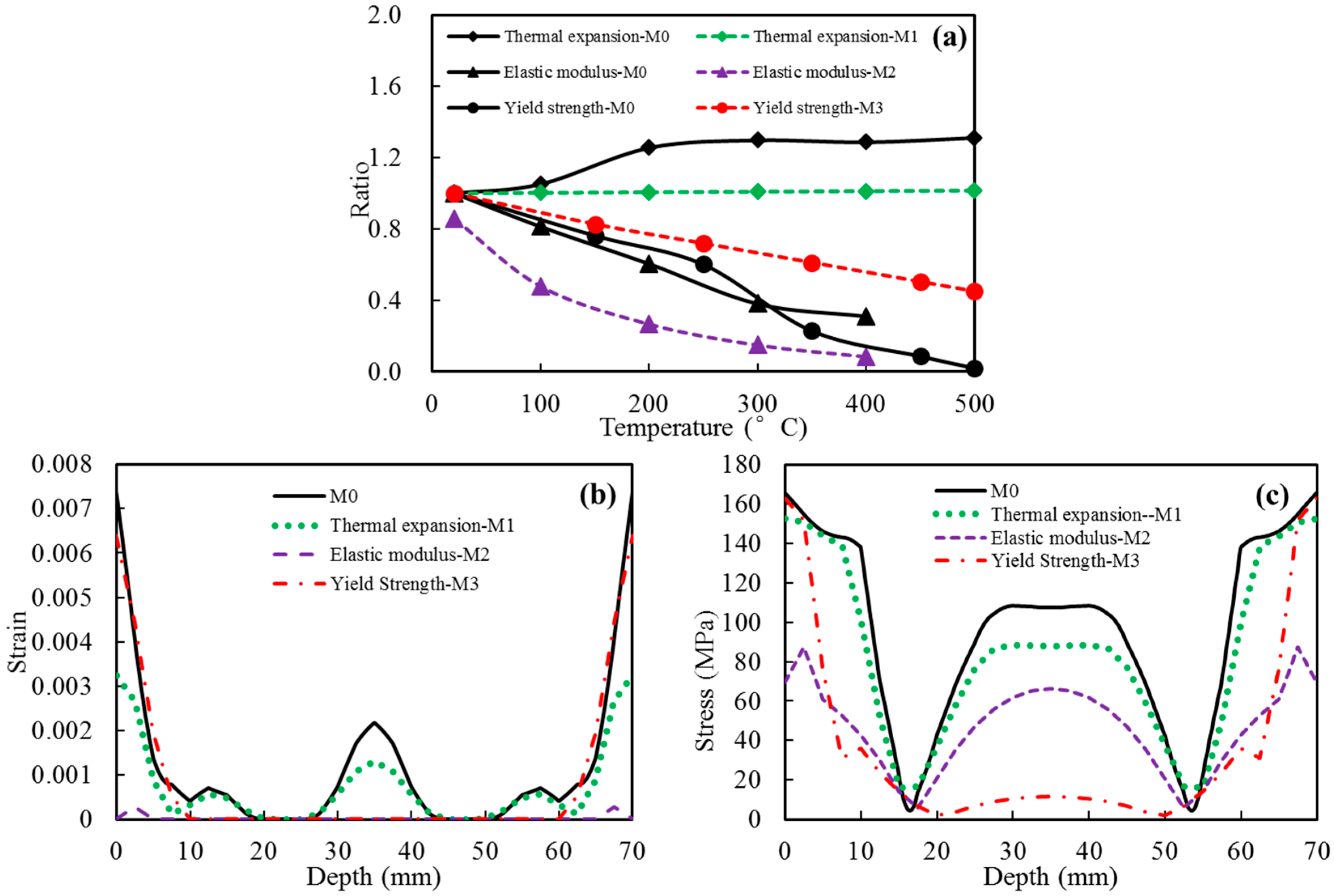
Figure 8 shows the simulation results for the samples (M0–M3) with different material properties. Equivalent plastic strain (PEEQ) and Mises stresses along the central line (L0) represent the plastic strains and residual stresses of the samples, respectively. As shown in Figure 8b,c, the plastic strains and residual stresses of the samples M1–M3 are lower than those of the sample M0. Figure 8a compares the adjusting material properties used for samples M1–M3 with the ones for sample M0. Like the treatments in Section 2.3, the values of every kind of measured material properties at 20 °C were considered to be reference values, and the material properties at different temperatures were divided by the corresponding reference value. Compared with the material properties used for sample M0, the thermal expansion coefficients used for sample M1 are smaller, the elastic moduli used for sample M2 are smaller, and the yield strengths for sample M3 are bigger. Reducing thermal expansion coefficients reduced thermal expansion and thermal stresses during quenching, which resulted in the decrease of plastic strains. Reducing the elastic modulus resulted in an increase in the allowable elastic strain at a certain thermal strain, and this led to the reduction in the plastic strain during quenching. The increase in the yield strength reduced the plastic strain at a certain thermal stress. Therefore, the plastic strains and residual stresses of samples M1–M3 are smaller than the ones of sample M0.
3.2. Influence of Cooling Rates at Different Temperatures on Residual Stress
The section above indicates that to produce a certain plastic strain, the magnitude of temperature difference should be increased with decreasing temperatures. For real components, the residual stresses are determined by inhomogeneous plastic deformations. The evolution of plastic strain and stress is affected by the temperature distributions in the components during quenching. The temperature difference increased with increasing cooling rate. At the same time, the cooling rates determine mechanical properties, and this relationship has been studied using time-temperature- properties (TTP) curves in our previous work [15]. To optimize the quenching process, this section will investigated the influence of cooling rates at different temperatures on the evolution of plastic strain and final residual stress by quenching the samples with different quenching technologies.
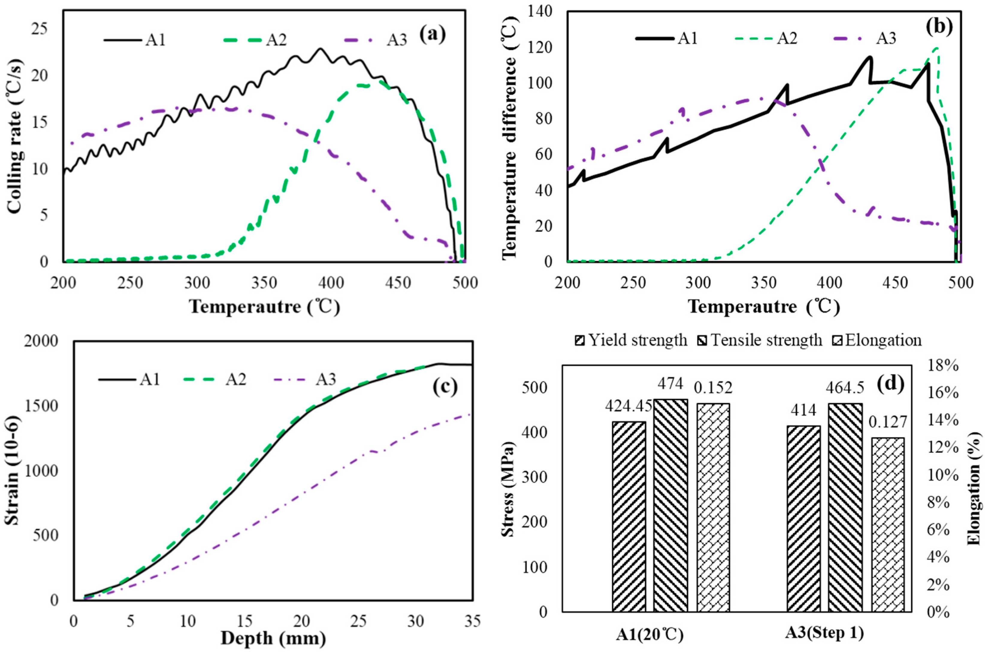
Figure 9 shows the cooling rates at P0, temperature differences between points P0 and P1, strains measured by the slitting method, and tensile properties of the samples. The results show that reducing the cooling rates in a low temperature range does not reduce residual stresses. However, an optimized step quenching process can minimize the residual stresses and result in good mechanical properties. As shown in Figure 9a,b, the cooling rates and temperature differences between P0 and P1 of Samples A1 and A2 are almost the same in the temperature range from 500 to 420 °C, and the cooling rates and temperature differences of Sample A2 are much lower than those of Sample A1 at temperatures below 400 °C. However, the residual stresses of the two samples are almost the same, as shown in Figure 9c. This means that changing the cooling rates at low temperatures does not change the residual stresses for the Samples A1 and A2. In the case of Sample A3, the cooling rates are lower at temperatures above 300 °C, especially above 450 °C, than those of Sample A1. The cooling rates are higher than those of the sample A1 at temperatures below about 300 °C. The temperature differences of Sample A3 are lower at temperatures above 400 °C and slightly higher at temperatures below 350 °C. However, the residual stresses of Sample A3 are much lower than those of Sample A1 due to the lower cooling rates at high temperatures. This is because plastic strain occurred more easily at high temperatures, according to the results and analysis presented in Section 3.1. Moreover, as shown in Figure 9d, the tensile properties of sample A3 are close to those of Sample A1, because the cooling rates are high in the quenching sensitivity range from 300 to 400 °C [15]. This means that residual stresses and mechanical performances can be balanced by employing an optimized quenching technology with low cooling rates in high temperature range and high cooling rates in other temperature ranges.
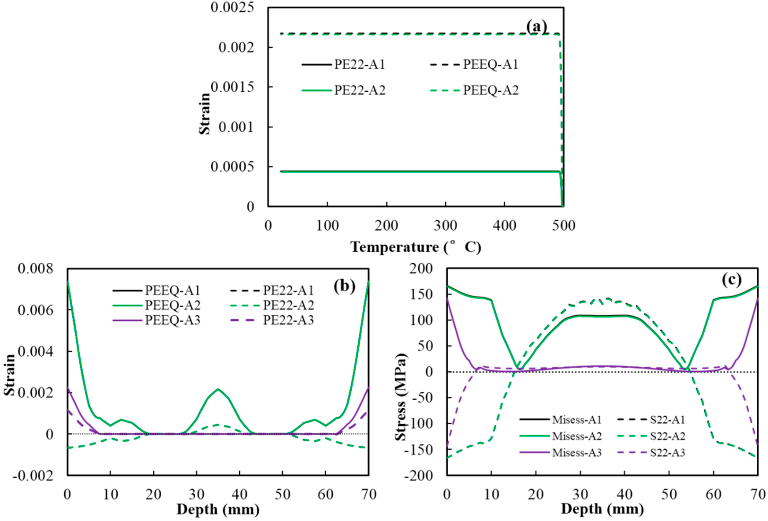
The numerical simulation method was used to further study the influence of cooling rates on the evolution of residual stress. Figure 10 shows the evolution of the plastic strain at P0, plastic strains and residual stresses along L0. As shown in Figure 10a, the plastic strains (plastic strains in the y direction (PE22) and equivalent plastic strain (PEEQ)) at P0 of Sample A1 and A2 vs. temperature curves are almost the same. The plastic strains reached the magnitudes at about 490 °C and remained unchanged thereafter; even the cooling rates of Sample A2 are much lower below 400 °C. According to the results and analysis presented in Section 3.1, to produce a certain plastic strain, the temperature difference should be increased with decreasing temperatures. This explains that reducing the cooling rates at low temperature range does not reduce the plastic strains at P0. Consequently, as shown in Figure 10b,c, the plastic strains (PE22 and PEEQ) and residual stress (Mises stress and principal stresses in the y direction (S22)) along L0 of the two samples are almost the same. Moreover, in the case of Sample A3, the step quenching technology produces lower plastic strains and residual stresses along L0 due to the low cooling rates at high temperatures. The results coincide with the experimental results in the above paragraph.
4. Discussion
The influence of temperature-dependent material properties on the evolution of plastic strain at different temperatures during the quenching process was investigated, and the influence of cooling rates at different temperatures on the evolution of plastic strain and residual stress for forged 2A14 aluminum alloy components during the quenching process was also analyzed.
During quenching process, the thermal expansions at high-temperature locations than at low-temperature locations. The difference in the thermal expansions resulted in thermal strains and stresses to balance the inhomogeneous thermal expansions. This usually produced inhomogeneous plastic strains, which resulted in residuals stress after the quenching treatment.
Equation (9) shows that the thermal expansion coefficients, elastic moduli, and yield strengths play key roles in determining the magnitude of plastic strains. Figure 8 shows that compared with the sample M0, decreasing the thermal expansion coefficients and increasing yield strengths at high temperatures decreases the residual plastic strains and stresses along the central line L0 of the sample M1 and M3, respectively; further, decreasing the elastic moduli decreases the residual plastic strains and stresses along line L0 of the sample M2. This can be explained as follows: During the quenching process, decreasing thermal expansion coefficient decreased the thermal expansion and thermal stress, which resulted in a decrease in the plastic strain. Further, increasing yield strength reduced the plastic strain at a certain thermal stress; reducing the elastic modulus resulted in the rise of allowable elastic strain at a certain thermal strain, and then led to the reduction in the plastic strain. The reduction in the plastic strains during quenching decreased residual plastic strains and stresses of the components.
The paragraph above implies that increasing thermal expansion coefficient and decreasing the yield strength causes an increase in the plastic strain. However, decreasing elastic modulus decreases the plastic strain. For the studied material, the thermal expansion coefficient increase with the increasing temperature; the elastic modulus and yield strength decrease with increasing temperature. Using the model in Section 2.1, the evolution of the plastic strain at different temperatures during quenching process was studied. Figure 7 shows that the plastic strain increases with increasing temperature at the same temperature difference between the two units; the plastic strain increases with increasing temperature difference at the same temperatures. This means that the influence of the thermal expansion coefficients and yield strengths changing with temperatures on plastic strains are more serious than the effect of the changes in the elastic moduli. Thus, the plastic strains increase with temperature.
Quenching residual stress of aluminum alloy components are caused by the inhomogeneous temperature distribution. Decreasing the temperature gradients decreases the plastic strain during the quenching process, resulting in lower residual stresses. Decreasing the cooling rates decreases the temperature gradient. Many papers reported that reducing the cooling rate can minimize residual stresses [10,15,23]. However, the above paragraphs in this section imply that for this material component, the residual plastic strains and stresses are mainly determined by the cooling rates in a high-temperature zone. Figure 9 shows that compared with the sample A1, reducing the cooling rates at low temperatures below 400 °C does not reduce the measured strains of the sample A2, as indicated by the slitting method results; in contrast, reducing the cooling rates at high temperatures above about 450 °C reduces the strains of sample A3 sharply, as per measurement results of the slitting method. The strains are in proportion with the residual stress of the samples. Figure 10 shows the residual strains and stresses simulation results along the central line L0 of the samples A1–A3, and they show a similar trend as the quenching experiment results. These results confirmed that the cooling rate at the high-temperature zone insignificantly affects the residual stress of this studied material component.
Time-temperature-properties (TTP) curves of this studied material [15] show that mechanical performances are mainly determined by cooling rates in the quenching sensitivity temperature range. According to this conclusion and the results presented above, an optimized step quenching technology was proposed to balance the residual stresses and mechanical properties. By quenching sample A3 with this cooling path, the residual stresses were reduced significantly and the tensile properties changed slightly, compared with sample A1 quenched with water at 20 °C, as shown in Figure 9 and Figure 10. In this quenching treatment, the cooling rates were low at high temperatures above 450 °C to minimize the residual stresses, and they increased in the other temperature ranges, resulting in good mechanical properties.
5. Conclusions
After analyzing and summarizing the results above, several main conclusions were inferred.
Plastic strains increase with the temperature when the temperature difference remains unchanged.
The cooling rates at high temperatures play a key role in determining the magnitude of residual stresses. Only reducing the cooling rates at low temperatures cannot reduce the residual stress and plastic strains.
Residual stresses and mechanical properties can be balanced with an optimized quenching technology. The cooling rates of the sample are low at high temperatures to reduce residual stress and are high at the other temperatures to improve mechanical properties.
Acknowledgments
This work was financially supported by State Key Laboratory of High Performance Complex Manufacturing (zzyjkt2014-02) and the fund of Jiangsu Province for the transformation of scientific and technological achievements (BA2015075).
Author Contributions
Yuxun Zhang, Shiquan Huang and Youping Yi conceived and designed the model, numerical simulation and experiments; Yuxun Zhang performed the experiments; Yuxun Zhang, Shiquan Huang and Hailin He analyzed the data; Youping, Yi contributed reagents/materials/analysis tools; Yuxun Zhang wrote the paper; Youping Yi, Shiquan Huang and Hailin He helped modify the manuscript.
Conflicts of Interest
The authors declare no conflict of interest.
References
- Xiao, Y.; Xie, S.; Liu, J.; Wang, T. Practical Handbook of Aluminum Technology; Metallurgical Industry Press: Beijing, China, 2005. [Google Scholar]
- Li, S.; Huang, Z.; Chen, W.; Liu, Z.; Qi, W. Quench sensitivity of 6351 aluminum alloy. Trans. Nonferr. Met. Soc. 2013, 23, 46–52. [Google Scholar] [CrossRef]
- Robinson, J.S.; Tanner, D.A.; Petegem, S.V.; Evans, A. Influence of quenching and aging on residual stress in Al–Zn–Mg–Cu alloy 7449. Mater. Sci. Technol. 2013, 28, 420–430. [Google Scholar] [CrossRef]
- Dolan, G.P.; Robinson, J.S. Residual stress reduction in 7175-T73, 6061-T6 and 2017A-T4 aluminium alloys using quench factor analysis. J. Mater. Process. Technol. 2004, 153, 346–351. [Google Scholar] [CrossRef]
- Shalvandi, M.; Hojjat, Y.; Abdullah, A.; Asadi, H. Influence of ultrasonic stress relief on stainless steel 316 specimens: A comparison with thermal stress relief. Mater. Des. 2013, 46, 713–723. [Google Scholar] [CrossRef]
- Citarella, R.; Carlone, P.; Lepore, M.; Sepe, R. Hybrid technique to assess the fatigue performance of multiple cracked FSW joints. Eng. Fract. Mech. 2016, 162, 38–50. [Google Scholar] [CrossRef]
- Lepore, M.A.; Citarella, R.; Carlone, P.; Sepe, R. DBEM crack propagation in friction stir welded aluminum joints. Adv. Eng. Softw. 2015, 101, 50–59. [Google Scholar]
- Citarella, R.G.; Cricrì, G.; Lepore, M.; Perrella, M. Assessment of Crack Growth from a Cold Worked Hole by Coupled FEM-DBEM Approach. Key Eng. Mater. 2013, 577–578, 669–672. [Google Scholar] [CrossRef]
- Koç, M.; Culp, J.; Altan, T. Prediction of residual stresses in quenched aluminum blocks and their reduction through cold working processes. J. Mater. Process. Technol. 2006, 174, 342–354. [Google Scholar] [CrossRef]
- Dong, Y.B.; Shao, W.Z.; Jiang, J.T.; Zhang, B.Y.; Zhen, L. Minimization of Residual Stress in an Al-Cu Alloy Forged Plate by Different Heat Treatments. J. Mater. Eng. Perform. 2015, 24, 2256–2265. [Google Scholar] [CrossRef]
- Jiang, G.; He, W.; Zheng, J. Mechanism and experimental research on high frequency vibratory stress relief. J. Zhejiang Univ. Eng. Sci. 2009, 43, 1269–1272. [Google Scholar]
- McGoldrick, R.T.; Saunders, H.E. Some experiments in stress-relieving castings and welded structures by vibration. J. Am. Soc. Nav. Eng. 1943, 55, 589–609. [Google Scholar] [CrossRef]
- Yang, Y.P. Understanding of Vibration Stress Relief with Computation Modeling. J. Mater. Eng. Perform. 2008, 18, 856–862. [Google Scholar] [CrossRef]
- Sun, Y.; Jiang, F.; Zhang, H.; Su, J.; Yuan, W. Residual stress relief in Al–Zn–Mg–Cu alloy by a new multistage interrupted artificial aging treatment. Mater. Des. 2016, 92, 281–287. [Google Scholar] [CrossRef]
- Zhang, Y.; Yi, Y.; Huang, S.; Dong, F. Influence of quenching cooling rate on residual stress and tensile properties of 2A14 aluminum alloy forgings. Mater. Sci. Eng. A 2016, 674, 658–665. [Google Scholar] [CrossRef]
- Li, H.Y.; Zeng, C.T.; Han, M.S.; Liu, J.J.; Lu, X.C. Time-temperature-property curves for quench sensitivity of 6063 aluminum alloy. Trans. Nonferr. Met. Soc. 2013, 23, 38–45. [Google Scholar] [CrossRef]
- Nallathambi, A.K.; Kaymak, Y.; Specht, E.; Bertram, A. Sensitivity of material properties on distortion and residual stresses during metal quenching processes. J. Mater. Process. Technol. 2010, 210, 204–211. [Google Scholar] [CrossRef]
- Chen, M. Elasticity and Plasticity, 1st ed.; China Science Publishing: Beijing, China, 2007; p. 421. [Google Scholar]
- Dong, X.; Zheng, T.; Yang, W.; Xiao, J. Coupled Thermal-mechanical Analysis of the Heat-treatment Process of an Aluminum Alloy Forging. Hot Work. Technol. 2002, 13, 17–18. [Google Scholar]
- Nervi, S.; Szabó, B.A. On the estimation of residual stresses by the crack compliance method. Comput. Method Appl. Mach. Eng. 2007, 196, 3577–3584. [Google Scholar] [CrossRef]
- Liu, W.; Guo, L.; Ma, Y.; Wang, J.; Liu, D. Microstructure and flow behavior of 2A14 aluminum alloy during hot deformation. Chin. J. Nonferr. Met. 2013, 23, 2091–2097. [Google Scholar]
- Zhao, Y.; Lin, S.; He, Z.; Wu, L. Numerical simulation of 2014 aluminium alloy friction stir welding process. Chin. J. Mech. Eng. 2006, 42, 92–97. [Google Scholar] [CrossRef]
- Tanner, D.A.; Robinson, J.S. Reducing residual stress in 2014 aluminium alloy die forgings. Mater. Des. 2008, 29, 1489–1496. [Google Scholar] [CrossRef]
Figure 1.
Two-unit model: (a) uniform temperatures at the beginning of quenching; and (b) temperature difference appeared during quenching.
Figure 1.
Two-unit model: (a) uniform temperatures at the beginning of quenching; and (b) temperature difference appeared during quenching.

Figure 2.
Schematic of quenching of a sample: (a) sizes and measured points (the unit used in this figure is “mm”); and (b) cutting plane of slitting method.
Figure 2.
Schematic of quenching of a sample: (a) sizes and measured points (the unit used in this figure is “mm”); and (b) cutting plane of slitting method.
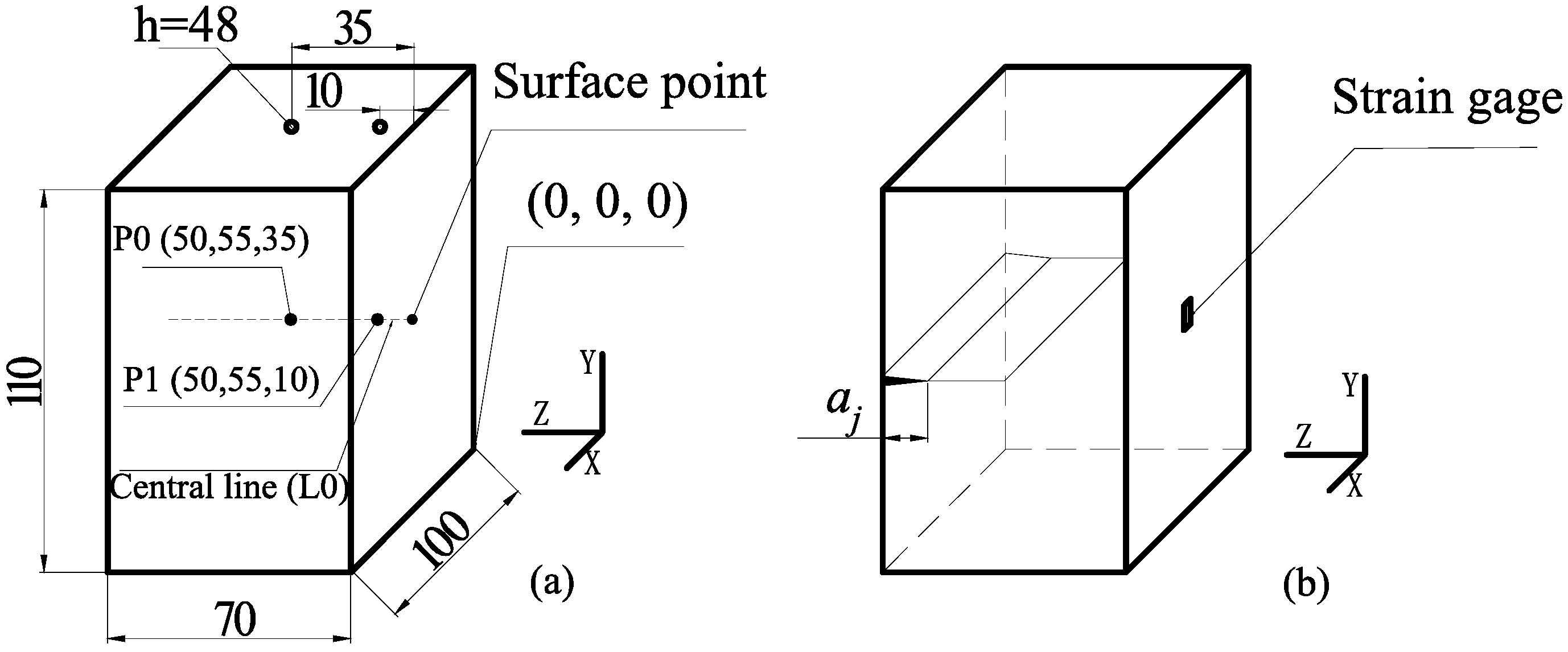
Figure 3.
Schematic of spray quenching experiment.
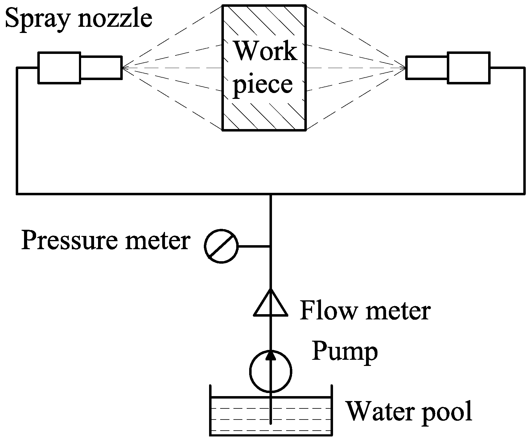
Figure 4.
Numerical simulation model.

Figure 5.
Yield strengths at different temperatures.

Figure 6.
Multiplier factors of thermal expansion coefficient, elastic modulus, and yield strength at different temperatures.
Figure 6.
Multiplier factors of thermal expansion coefficient, elastic modulus, and yield strength at different temperatures.

Figure 7.
Plastic strains of unit i of the model at different temperatures with a certain temperature difference (Tg).
Figure 7.
Plastic strains of unit i of the model at different temperatures with a certain temperature difference (Tg).
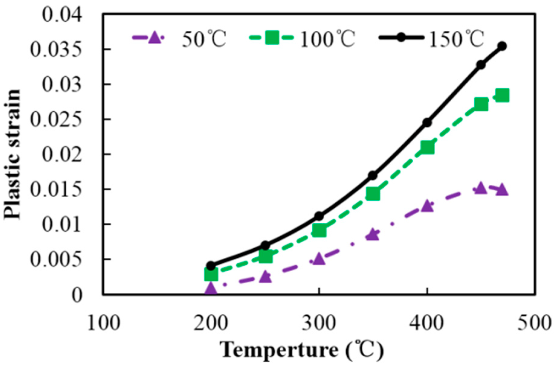
Figure 8.
Residual equivalent plastic strain (PEEQ) and Mises stresses along the central line L0 of the sample (110 mm × 100 mm × 70 mm) in Figure 2a using different thermal expansion coefficients, elastic moduli, and yield strengths: (a) normalized measured and adjusting material properties; (b) PFEQ; and (c) Mises stresses.

Figure 9.
Results of Samples A1–A3 with different quenching technology: (a) cooling rates at P0 during the quenching process; (b) temperature differences between points P0 and P1 during the quenching process; (c) strains measured by the slitting method after quenching treatment; and (d) tensile properties after aging treatments.

Figure 10.
Simulation results of the quenching samples: (a) evolution of the plastic strain (plastic strains in the y direction (PE22) and equivalent plastic strain (PEEQ)) at point P0; (b) plastic strains (PE22 and PEEQ) along the central line L0; and (c) residual stresses (Mises stress and principal stresses in the y direction (S22)) along L0.


Table 1.
Nomenclature.
| T | Temperature |
| ∆T | temperature difference between the temperature of the unit and reference temperature 0 °C |
| Tg | temperature difference between the two units of the model |
| thermal expansion coefficient | |
| E | elastic modulus |
| Ep | plastic modulus |
| σ0.2 | yield strength |
| i | number of the unit |
| εT | thermal expansion strain |
| ε | total strain |
| εe | elastic strain |
| εp | plastic strain |
| σ | thermal stress |
| PEEQ | equivalent plastic strain |
| PE22 | plastic strain in y direction |
| S22 | stress in y direction |
Table 2.
Plastic moduli at different temperatures.
| Temperature (°C) | 30 | 130 | 230 | 330 | 430 | 530 |
|---|---|---|---|---|---|---|
| Ep (MPa) | 9000 | 5000 | 2000 | 1000 | 400 | 200 |
Table 3.
Chemical composition of the studied material (wt %).
| Cu | Mg | Mn | Si | Fe | Ni | Zn | Ti | Al |
|---|---|---|---|---|---|---|---|---|
| 4.28 | 0.6 | 0.81 | 0.94 | 0.15 | 0.003 | 0.01 | 0.04 | Balance |
Table 4.
Heat treatments applied to 2A14 aluminum alloy samples.
| Samples | Solution Treatment | Quenching Technology | Ageing Treatment |
|---|---|---|---|
| A1 | 500 °C/4 h | 20 °C | 165 °C/9 h |
| A2 | 500 °C/4 h | Step 1: 20 °C Step 2: air | 165 °C/9 h |
| A3 | 500 °C/4 h | Spray quenching | 165 °C/9 h |
Table 5.
Thermal properties.
| Temperature (°C) | 20 | 100 | 200 | 300 | 400 | 500 |
|---|---|---|---|---|---|---|
| Conductivities (W·m−1·K−1) | 114.3 | 122.3 | 130.8 | 145.1 | 124.5 | 122.7 |
| Specific heat capacities (J·kg−1·K−1) | 809 | 860 | 897 | 922 | 872 | 985 |
| Elasticity moduli (GPa) | 81.5 | 66.2 | 49.3 | 31.0 | 25.3 | -- |
| Thermal expansion coefficients (10−5) | 2.08 | 2.19 | 2.61 | 2.70 | 2.68 | 2.73 |
Table 6.
Simulation scheme.
| Samples Material Properties | M0 | M1 | M2 | M3 |
|---|---|---|---|---|
| Thermal expansion coefficients | -- | adjusting | -- | -- |
| Elasticity moduli | -- | -- | adjusting | -- |
| Yield strengths | -- | -- | -- | adjusting |
© 2017 by the authors. Licensee MDPI, Basel, Switzerland. This article is an open access article distributed under the terms and conditions of the Creative Commons Attribution (CC BY) license (http://creativecommons.org/licenses/by/4.0/).
Share and Cite
MDPI and ACS Style
Zhang, Y.; Yi, Y.; Huang, S.; He, H. Influence of Temperature-Dependent Properties of Aluminum Alloy on Evolution of Plastic Strain and Residual Stress during Quenching Process. Metals 2017, 7, 228. https://doi.org/10.3390/met7060228
AMA Style
Zhang Y, Yi Y, Huang S, He H. Influence of Temperature-Dependent Properties of Aluminum Alloy on Evolution of Plastic Strain and Residual Stress during Quenching Process. Metals. 2017; 7(6):228. https://doi.org/10.3390/met7060228
Chicago/Turabian StyleZhang, Yuxun, Youping Yi, Shiquan Huang, and Hailin He. 2017. "Influence of Temperature-Dependent Properties of Aluminum Alloy on Evolution of Plastic Strain and Residual Stress during Quenching Process" Metals 7, no. 6: 228. https://doi.org/10.3390/met7060228
Note that from the first issue of 2016, this journal uses article numbers instead of page numbers. See further details here.