Torsional Fatigue Strength of Newly Developed Case Hardening TRIP-Aided Steel


1
School of Science and Technology, Shinshu University, 380-8553 Nagano, Japan
2
Institute for Materials Research, Tohoku University, 980-8557 Sendai, Japan
3
Ichinomiya Works, Sintokogio, Ltd., 441-1205 Toyokawa, Japan
*
Author to whom correspondence should be addressed.
Metals 2017, 7(9), 375; https://doi.org/10.3390/met7090375
Submission received: 4 August 2017
/
Revised: 13 September 2017
/
Accepted: 13 September 2017
/
Published: 15 September 2017
Abstract
:The torsional fatigue strength of newly developed case hardening steel, i.e., transformation-induced plasticity-aided martensitic steel subjected to vacuum carburizing followed by fine particle peening, was investigated for the fabrication of downsized precision gears with high torque capacity and wear resistance. The surface-hardened layer properties—i.e., high Vickers hardness, high compressive residual stress, and a large amount of retained austenite—considerably increased the torsional fatigue limits of vacuum-carburized and fine particle peened TM and JIS-SNCM420 steels, although the notch-sensitivity to fatigue was increased. The relation between torsional and rotational bending fatigue limits for the smooth specimens was found to be between the maximum principal stress and the minimum shear strain energy criterions. On the other hand, this relation for the notched specimens was represented through the maximum principal stress criterion.
1. Introduction
Several industrial precision gears are widely used as power transmitting gears, since not only can they carry larger loads but also the dynamic load and the noise level experienced during the operation are minimal [1]. As the precision gears undergo cyclic bending-torsion loadings [2,3,4,5], high rotational bending, torsional, and bending–torsional fatigue strengths are required. In general, two kinds of gear tooth damage can occur due to material fatigue under repeated loading-pitting and tooth breakage in the tooth root area [6]. Case hardenings such as gas-carburizing and surface- quenching provides improved contact and bending-torsional fatigue performance of steels with respect to through hardened gears [7] and other mechanical components. In addition, the effects of several variables—such as the specimen geometry, level of stress concentration factors, stress ratio, or the loading histories—on the fatigue performance must investigate.
Recently, the demand for transmission precision gears with high torque capacity and high wear resistance has increased; in addition, the gears are being downsized to reduce energy consumption [8]. Next-generation structural steels such as ultrahigh-strength transformation-induced plasticity (TRIP)-aided steels with a martensite/bainitic ferrite matrix—i.e., TRIP-aided martensitic (TM) steel [9,10,11], quenching and partitioning steel [12,13], and nanostructured bainitic steel [14,15]—are being considered for use in fabricating precision gears owing to their high toughness and fatigue strength [10,11,12,13,14,15,16]. Sugimoto et al. [17,18] reported that fine particle peening increases the rotational bending and torsional fatigue strength of heat-treated TM steel by imparting a significantly high hardness and compressive residual stress onto the surface-hardened layer. Many other researchers have also corroborated that shot peening increases the fatigue strength of heat-treated steels [19,20]. The fatigue strength of TM steel can be further improved through gas- or vacuum-carburizing with shot peening and/or fine particle peening [21,22,23,24,25]. There have been a few reports on the microstructure and rotational bending fatigue strength of carburized TM steel subjected to fine particle peening [26,27]. However, to the best of our knowledge, there have been no investigations into the effects of vacuum carburization, followed by fine particle peening, on the torsional fatigue strength of TM steel.
In this study, the torsional fatigue properties of smooth and notched specimens in newly developed case hardening steel, i.e., 0.2%C-1.5%Si-1.5%Mn-1.0%Cr-0.05%Nb TM steel subjected to vacuum-carburizing and fine particle peening, were investigated. The fatigue limits were compared with the rotational bending fatigue properties. Moreover, a mechanism for controlling their fatigue properties was proposed by applying the surface-hardened layer properties, such as the surface roughness, hardness, and residual stress, as well as the volume fractions of untransformed retained austenite and strain-induced martensite.
2. Materials and Methods
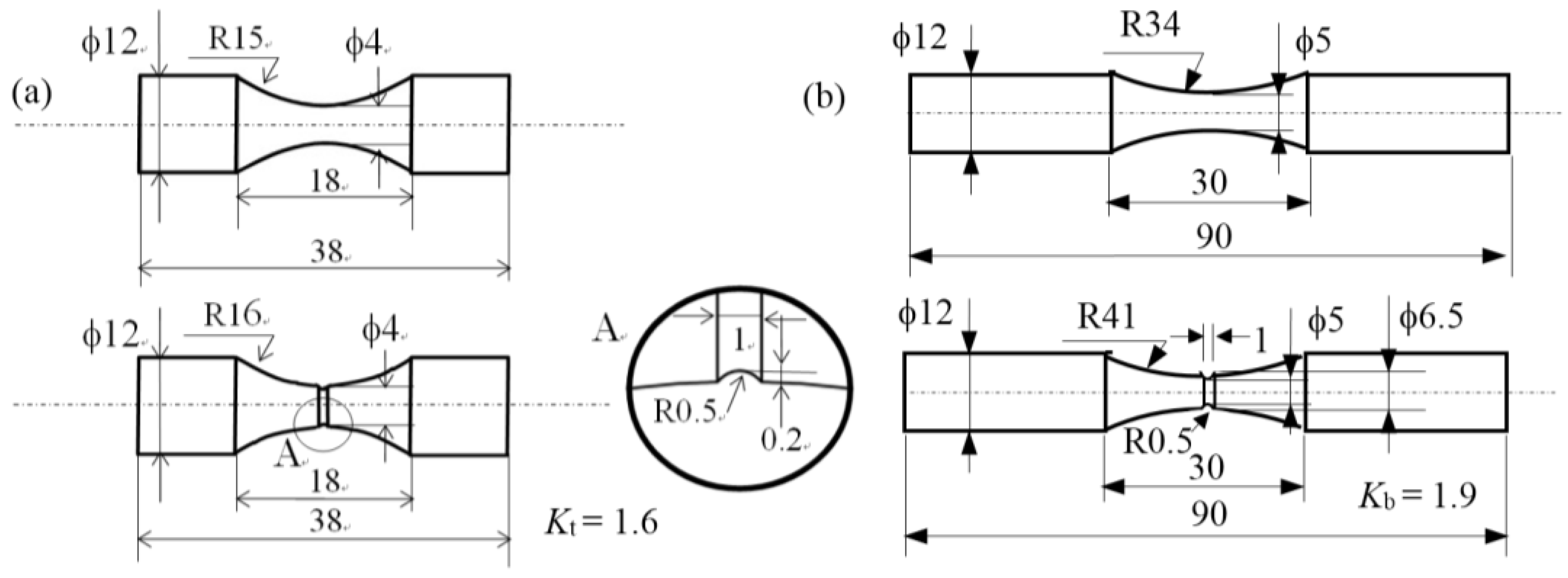
Steel slabs were vacuum-melted, hot-forged, and hot-rolled into 13-mm-diameter bars. The chemical composition of these steel slabs is provided in Table 1. For the torsional and rotational bending fatigue tests, smooth and notched specimens (dimensions shown in Figure 1) were machined from the bars. The stress concentration factors of the notched specimens were estimated to be 1.6 for torsion and 1.9 for bending using the data of stress concentration factors numerically calculated by Nishitani [28]. Smaller net areas of torsional smooth and notched specimens than those of bending specimens are caused by the lower power of the torsional testing machine.
The specimens were subjected to vacuum carburization and quenching in oil at 80 °C followed by tempering at 180 °C for 90 min (Figure 2) in a vacuum-carburizing batch furnace (VCB, IHI Machinery and Furnace Co., Ltd., Tokyo, Japan). For comparison, commercial JIS-SNCM420 steel bars of 13-mm in diameter and with the chemical composition given in Table 1 were prepared, and the vacuum carburization and tempering process was carried out on smooth and notched specimens having the same dimensions as the TM steel. In addition, TM and SNCM420 steels subjected to quenching and tempering heat treatment [18] were also prepared.
Fine particle peening was carried out on the surface of the specimens under the conditions given in Table 2. The microstructure of the steels was observed using a field-emission scanning electron microscope (FE-SEM; JSM-6500F, JEOL Ltd., Tokyo, Japan), which was equipped with an electron backscatter diffraction system (EBSD; OIM system, TexSEM Laboratories Inc., Draper, UT, USA). The specimens used in the FE-SEM-EBSD analysis were first ground using alumina powder and colloidal silica, and then subjected to ion thinning. The Vickers hardness was measured using a micro Vickers hardness tester (HVM, Shimadzu Co., Kyoto, Japan). The testing load was 4.9 N. The surface roughness was measured using a laser scanning microscope (VK-8510, Keyence Co., Milton Keynes, UK) and evaluated based on the maximum roughness height (Rz, JIS B0601:2001). The volume fraction of the retained austenite phase was quantified from the integrated intensity of the (200)α, (211)α, (200)γ, (220)γ, and (311)γ peaks obtained using an X-ray diffractometer (RINT2000, Rigaku Co., Tokyo, Japan) [29]. The cosα method [30] was applied to the X-ray studies of the residual stress in a longitudinal direction using an X-ray residual stress analyzer (μ-X360, Pulstec Ind. Co. Ltd., Hamamatsu, Japan). The measurement conditions and material constants employed were as given in a previous study [30].
Fatigue tests were conducted using a torsional fatigue testing machine (PBF-30X, Tokyo Kikai Seisakusho, Ltd., Tokyo, Japan) at 25 °C with a sinusoidal wave of 25 Hz at a stress ratio of R = −1, and a rotating bending fatigue testing machine (H-7, Shimadzu Co., Kyoto, Japan) at 25 °C with a sinusoidal wave of 3000 rpm and a stress ratio of R = −1. The fatigue limit was defined as the maximum value of the stress amplitude without failure for up to 1.0 × 10⁷ cycles. To calculate the nominal torsional and bending stresses for notched specimens, net area was adopted for the notched specimens.
3. Results
3.1. Microstructure and Mechanical Properties of Surface-Hardened Layer
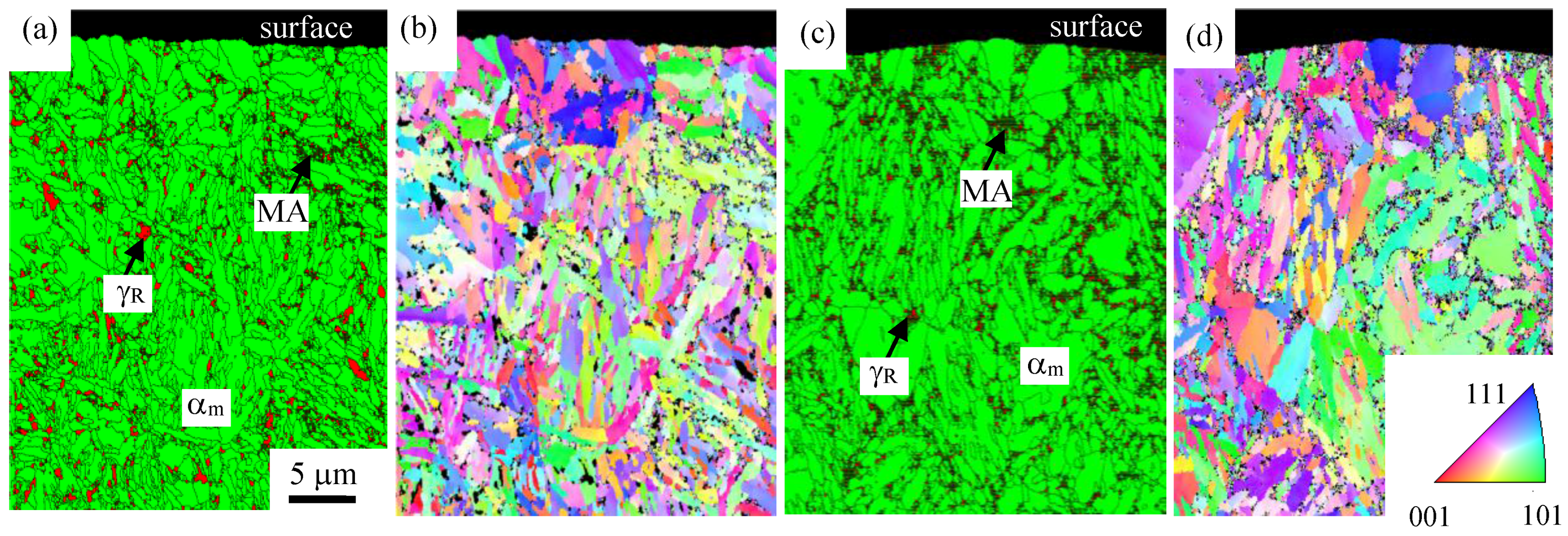
Results from the EBSD analyses of the as-vacuum-carburized TM and SNCM420 steels are shown in Figure 3. The microstructure of the TM and SNCM420 steels was characterized by the mixture of an α′-martensite matrix with a wide lath structure, martensite-austenite (MA)-like phases, and retained austenite phases. The microstructure near the surface was coarser than that in the interior for both steels. Two types of retained austenite, i.e., an island type of retained austenite in the matrix and a filmy type of retained austenite in the MA-like phase, were observed in the TM and SNCM420 steels. The TM steel contained a larger amount of isolated island type of retained austenite, a smaller amount of MA-like phase, and a finer microstructure than the SNCM420 steel. Most of the MA-like phases seemed to be located along the prior austenitic, packet, and block boundaries.
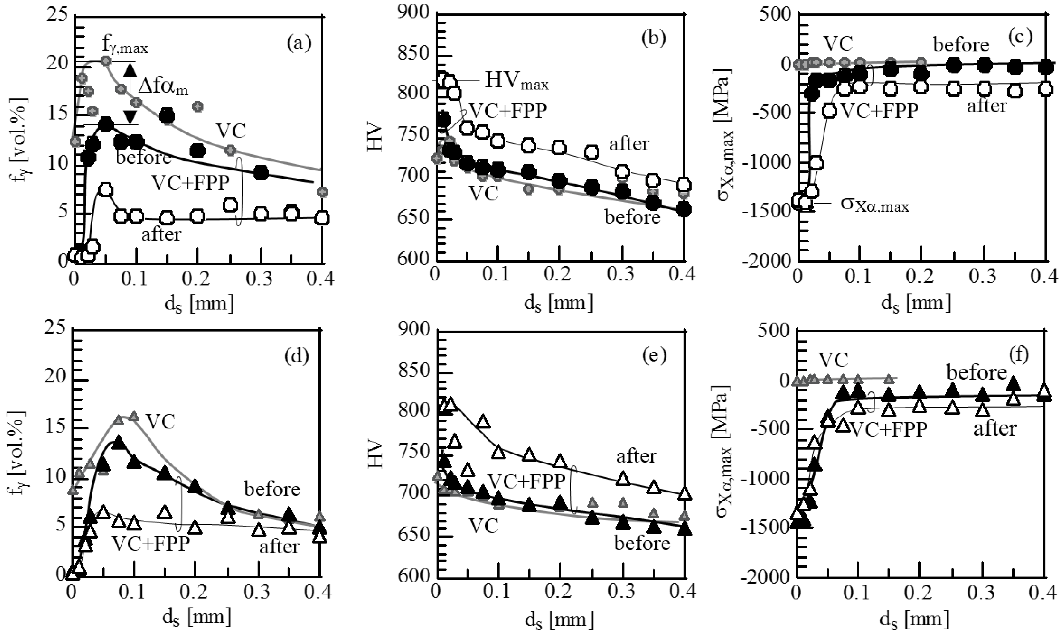
Figure 4 shows the distributions of the volume fraction of untransformed retained austenite, Vickers hardness, and X-ray residual stress of the α-bcc phase in the surface-hardened layer of vacuum-carburized TM and SNCM420 steels subjected to fine particle peening. The figure also shows data on as-vacuum-carburized steels (gray marks and lines). During fine particle peening, a large amount of retained austenite was transformed into martensite on the surface, at a depth of less than 50 μm from the surface. The hardness was at maximum on the surface or at the subsurface. The compressive residual stress reached the maximum level at just below the undersurface (at a depth of 10 μm from the surface). When the surface-hardened layer properties of both steels were compared, the TM steel was characterized by a higher retained austenite fraction, hardness, and compressive residual stress compared to the SNCM420 steel, as well as a higher volume fraction of strain-induced martensite (Δfαm in Figure 4a). A white layer (nanostructure or amorphous structure) [19,31] was not observed on the surface of either type of steel after fine particle peening. The maximum values of the surface-hardening properties are given in Table 3. Both types of steel possessed the same surface roughness.
Figure 5 shows engineering stress-strain curves of smooth specimen and stress-displacement curves of notched specimen in TM and SNCM420 steels subjected to vacuum carburization without and with fine particle peening. The tensile properties are provided in Table 3. All specimens generated brittle-like fracture. Fine particle peening after vacuum-carburization increased the flow stress, tensile strength, fracture strain, and reduction of area in both steel types. The notch tensile strengths of both steels also increased after fine particle peening. The notch strength ratios of both steels were less than 1.0, indicating the occurrence of notch weakening.
3.2. Fatigue Properties
The curves of the nominal shear and bending stress amplitude versus the number of cycles of the vacuum-carburized and fine particle peened TM and SNCM420 steels are shown in Figure 6. The fatigue lives and limits of these steels, as well as those of the heat-treated steels, are given in Table 4 and Table 5, respectively. Regarding the torsional fatigue, vacuum-carburizing and subsequent fine particle peening increased the fatigue limits of the smooth and notched specimens by 47% and 19% in TM steel and by 56% and 30% in SNCM420 steels, respectively, as compared with the heat-treated and fine particle peened steels [18]. The increases in ratios of the fatigue limits of TM steel were smaller than those of SNCM420 steel. However, the fatigue limits of smooth and notched specimens of TM steel were slightly higher than those of SNCM420 steel. The notch sensitivity of both steels was increased compared to that of heat-treated steels.
As shown in Table 5, the rotational bending fatigue limits of the smooth specimens for both types of steel were also significantly increased through vacuum-carburizing and fine particle peening. The notched fatigue limit of SNCM420 steel increased when using vacuum-carburizing treatment, whereas the notched fatigue limit of TM steel decreased as compared to that of heat-treated steel. The notch-sensitivity to the rotational bending fatigue in both steel types was higher than that for the corresponding torsional fatigue.
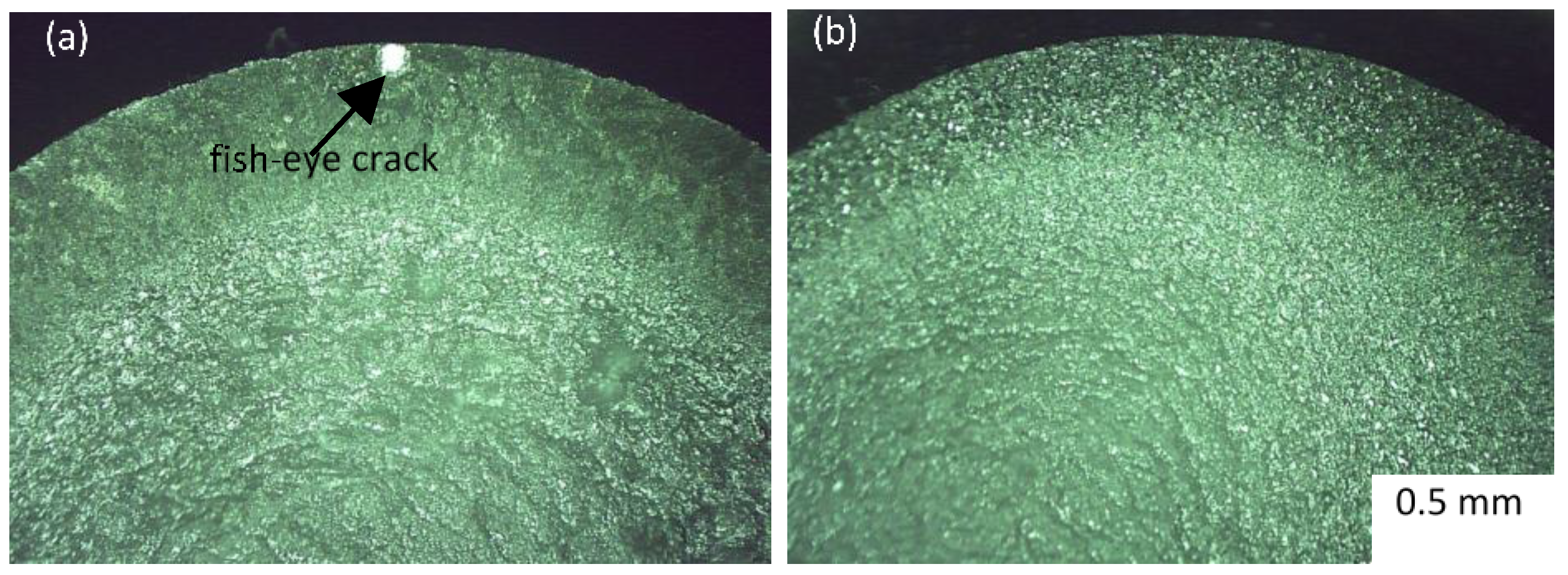
In all torsional specimens subjected to vacuum-carburization and fine particle peening, crack origins leading to fatigue fracture were observed on the surface (Figure 7). On the other hand, the rotational bending smooth specimens of vacuum-carburized and fine particle peened TM steel fractured in a fish-eye crack pattern at the subsurface region (at a depth of less than 50 μm from the surface) (Figure 8a), although surface crack fractures were occasionally observed. This may be associated with a difference in the stress state (in the torsion and uniaxial tension). No distinct fish-eye cracks were observed in the fracture surface of the rotational bending notched specimens of the TM steel (Figure 8b). Non-propagating cracks were not observed on the surface of any of the non-fractured specimens tested in terms of torsional and rotational bending. According to Sugimoto et al. [11], only surface crack fractures have been observed in all heat-treated specimens subjected to fine particle peening [17,18].
The surface-hardened layer properties after fatigue tests at the stress amplitude of the fatigue limit are shown in Figure 4. A large amount of retained austenite transformed into martensite during the fatigue test in the TM and SNCM420 steels. The Vickers hardness of the TM and SNCM420 steels after the fatigue tests increased considerably, whereas the maximum compressive residual stress slightly decreased, with an increase in compressive residual stress occurring inside the specimen.
3.3. Relationship between Torsional and Rotational Bending Fatigue Limits
Figure 9a shows the relations between the torsional and rotational bending fatigue limits of smooth and notched specimens of TM and SNCM420 steels subjected to vacuum carburization and subsequent fine particle peening. For comparison, the relations of the heat-treated steels are shown in Figure 9b. For vacuum-carburized and fine particle peened TM and SNCM420 steels, the relation for the smooth specimens was between the maximum principal stress and the minimum shear strain energy criterions, i.e., τ = σ/√3. When compared with those of the heat-treated and subsequent fine particle peened steels, both relationships shifted toward the maximum principal stress criterion. This can be related to the decreased rotational bending fatigue limits. Wakita et al. [32] reported that the relation for the smooth specimen of shot peened high strength spring steel (0.6%C-2.0%Si-0.9%Mn) was between the maximum principal stress and the minimum shear strain energy criterions, which is similar to the vacuum-carburized steels subjected to fine particle peening.
The relation regarding the notched specimens was represented using the maximum principal stress criterion, i.e., τ = σ (τ, shear stress; σ, normal stress). The idea that the relations for notched specimens are given by the maximum principal stress is not sufficiently demonstrated. It probably depends on the stress concentration factor. For lower stress concentration values, the relation is expected to be close to the smooth case, and for higher stress concentration factors, no conclusions can be drawn. We do not know if the same criterion is adequate.
4. Discussion
The relations between the torsional and rotational bending fatigue limits of smooth and notched specimens in TM and SNCM420 steels subjected to vacuum carburization and subsequent fine particle peening shifted toward the maximum principal stress criterion, compared with the relations of heat-treated both steels, especially in the smooth specimens (Figure 9). This could be related to the decreased rotational bending fatigue limits. In the following, we discuss the reason why the rotational bending fatigue limits decreased considerably in the smooth specimens.
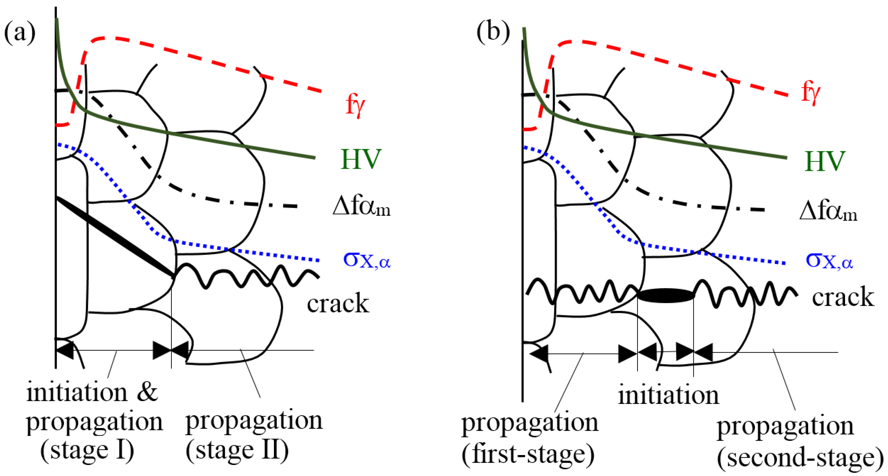
In general, fine particle peening increases the (i) hardness and (ii) compressive residual stress in the surface-hardened layer of heat-treated and carburized steels through severe plastic deformation and strain-induced martensite transformation of retained austenite [10,16,19,21,22,23,24,25,26,31]. In addition, the peening produces a small surface roughness. If a fish-eye crack initiates at the subsurface layer of the specimen and subsequently propagates to the surface [33], as shown in Figure 10b, the subsurface-hardened properties characterized by (i) and (ii) suppress the propagation to the surface (first-stage propagation) of the fish-eye crack, as well as in case of crack initiation on the surface (Figure 10a). Therefore, the surface-hardened layer properties and the depth of the crack initiation origin can be expected to be connected with the fatigue limits and the relation between the torsional and rotational bending fatigue limits in the smooth specimen of TM steel subjected to vacuum carburization and subsequent fine particle peening.
Using JIS-SCM822H steel subjected to shot peening after gas carburization, Matsui et al. [21,22] proposed the idea that if fatigue cracks initiate at the steel surface, the rotational bending fatigue limit (σw) of the smooth specimen is related to the sum of the estimated yield stress (σY,est) and the absolute value of the maximum compressive residual stress {abs(σXα,max)} before fatigue deformation, as
σw = 0.3891 × {σY,est + abs(σXα,max)}, (2363 MPa < σY,est + σXα,max < 4505 MPa)
The value of σY,est can be estimated from the maximum hardness (HVmax) using.
where YS/TS is the yield ratio defined by the ratio of yield stress to tensile strength (assumed by Matsui et al. [21,22] to be 0.95).
σY,est = (HVmax/3) × 9.80665 × (YS/TS)
Figure 11 shows the variations in torsional and rotational bending fatigue limits as a function of σY,est + abs(σXα,max) for vacuum-carburized and subsequently fine particle peened TM and SNCM420 steels. For comparison, fatigue limits [18] for the heat-treated TM and SNCM420 steels subjected to fine particle peening under the same conditions are also plotted in Figure 11 (see open marks). This figure indicates that the slope referring to the smooth torsional and rotational bending fatigue limits of vacuum-carburized and fine particle peened TM and SNCM420 steels is smaller than that referring to both fatigue limits of heat-treated steels, especially in the rotational fatigue limits.
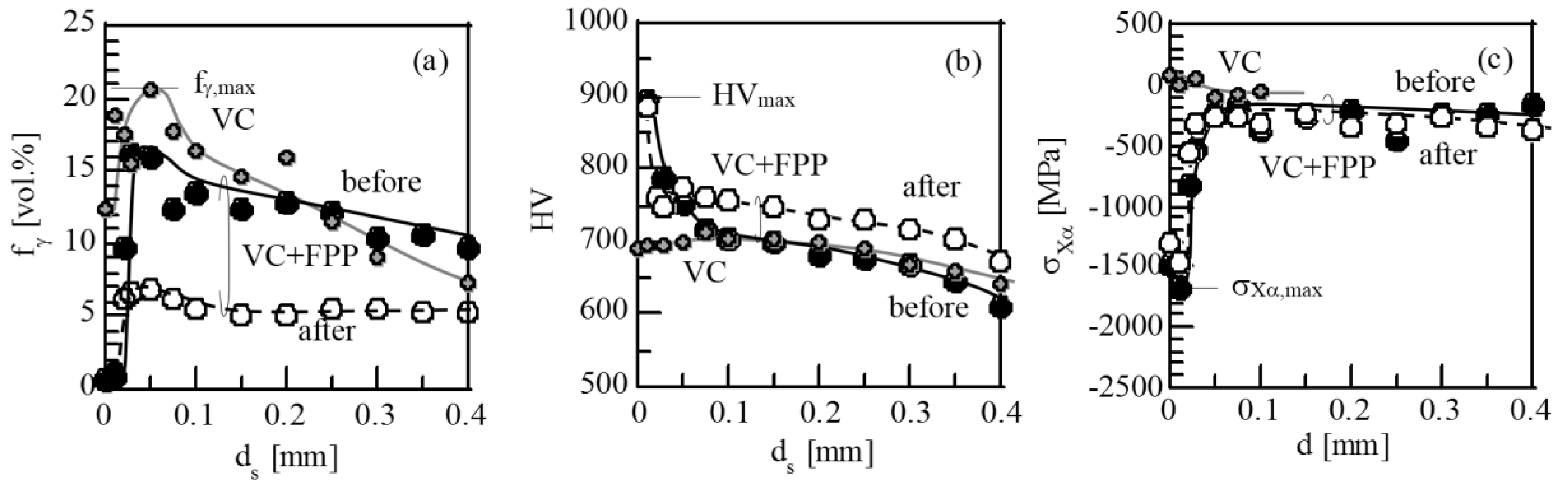
In this study, the subsurface hardness of vacuum-carburized and fine particle peened TM steel considerably increased during torsional fatigue deformation, accompanied with only a slight decrease in compressive residual stress (Figure 4c), resulting from the strain-induced martensite transformation of a large amount of retained austenite (Figure 4a). In addition, surface cracks initiated in the torsional fatigue specimens (Figure 7a), and fish-eye cracks were observed at the subsurface of the rotational bending smooth specimens (Figure 8a). These results indicate that the fatigue limits are likely related to the variations in the surface-hardened layer properties developed during fatigue deformation, and the depth of the crack initiation origin [18,27]. As shown in Figure 12, the surface-hardened properties of the smooth specimen in the TM steel after rotational bending fatigue deformation were nearly the same as those after torsional fatigue deformation [26,27]. Thus, the large difference between torsional and rotational bending fatigue can be estimated from the depth of the crack initiation origin, i.e., a surface crack for torsional fatigue (Figure 7a), and a fish-eye crack for rotational bending fatigue (Figure 8a). In the case of a fish-eye crack fracture, the surface-hardened layer properties have a small contribution to the crack initiation as compared with the case of surface crack initiation. Therefore, it is possible that the large downward shift of the rotational bending fatigue limits of smooth specimens of vacuum-carburized TM steel (Figure 11b) is caused by the fish-eye fracture at the subsurface region.
In Figure 11a, the slope referring to the torsional fatigue limits of the notched specimens of vacuum-carburized and fine particle peened TM and SNCM420 steels was much smaller than the slope referring to the fatigue limits of heat-treated and fine particle peened steels. In this case, the decrease in the slope of the torsional fatigue limit was relatively smaller than that of the rotational bending fatigue limit. No distinct fish-eye crack was observed in the torsional notched specimens (Figure 8b). Therefore, the large decrease in the slope of vacuum-carburized and fine particle peened steels may be mainly caused by low notch strength ratio (Table 3) or notch weakness (low notch constraint). The notch-sensitivity to the torsional fatigue was lower than that for the rotational bending fatigue (Table 5). This result indicates that the torsional fatigue limit is more insensible to the notch weakness than the rotational bending fatigue limit. Lower notch sensitivity of the heat-treated and fine particle peened steels may be caused by the notch strengthening [18].
Jo et al. [5] explained the fatigue behavior of smooth specimens of carburized steel with fish-eye crack at the subsurface layer using the two-layer model based on case and core material properties. They also found that the two-layer model used in conjunction with von Mises effective stress provided close prediction of fatigue behavior, as compared to the experimental results, under torsion loadings. This is different from our result in that rotational bending fatigue limits for the smooth specimens was between the maximum principal stress and the minimum shear strain energy (von Mises) criteria. The difference in results by Jo et al. [5] and our research group may be caused by the surface hardened layer properties, namely the case hardening steel by Jo et al. [5] possessed conspicuously lower hardness and compressive residual stress than the present case-hardening TM and SNCM420 steels.
5. Conclusions
The torsional fatigue properties of newly developed case hardening steel, i.e., 0.2%C-1.5%Si-1.5%Mn-1.0%Cr-0.05%Nb TM steel subjected to vacuum carburization and subsequent fine particle peening, were investigated for the fabrication of precision gears. The main results are summarized as follows:
- (1)
- Vacuum carburizing followed by fine particle peening enhanced the torsional fatigue limits of the TM steel, although the process increased the notch sensitivity to fatigue compared to heat-treated and fine particle peened steels.
- (2)
- The high torsional fatigue limits were associated with high Vickers hardness, compressive residual stress through severe plastic deformation, and strain-induced martensitic transformation during fine particle peening, as well as through a strain-induced transformation during fatigue deformation because fatigue cracks initiated on the surface or at the subsurface.
- (3)
- The relation between torsional and rotational bending fatigue limits for the smooth specimens was between the maximum principal stress and the minimum shear strain energy criteria. On the other hand, the relation for the notched specimens was followed by the maximum principal stress criterion. When compared with those of heat-treated and fine particle peened steels, both relations shifted toward the maximum principal stress criterion, especially for the notched specimens. The relation of the smooth specimen was related to fish-eye cracks, which preferentially initiated during rotational bending fatigue. On the other hand, the relation of the notched specimen was expected to be mainly caused by notch weakness.
Acknowledgments
This study was supported by a Grant-in-Aid for Scientific Research (B), the Ministry of Education, Science, Sports and Culture, Japan (No. 2013-25289262). We also thank Editage (http://www.editage.jp) for English language editing.
Author Contributions
Koh-ichi Sugimoto is the main contributor to this research work. He mainly analyzed the data and made the first draft the paper; Tomohiko Hojo and Yuta Mizuno performed the experimental work and proofread the paper.
Conflicts of Interest
The authors declare no conflict of interest.
References
- Asi, O. Fatigue failure of a helical gear in a gearbox. Eng. Fail. Anal. 2006, 13, 1116–1125. [Google Scholar] [CrossRef]
- Marciniak, Z.; Rozumek, D.; Macha, E. Fatigue lives of 18G2A and 10HNAP steels under variable amplitude and random non-proportional bending with torsion loading. Int. J. Fatigue 2008, 30, 800–813. [Google Scholar] [CrossRef]
- Firat, M. A numerical analysis of combined bending-torsion fatigue of SAE notched shaft. Finite Elem. Anal. Des. 2012, 54, 16–27. [Google Scholar] [CrossRef]
- Branco, R.; Costa, J.D.; Antunes, F.V. Fatigue behavior and life prediction of lateral notched round bars under bending-torsion loading. Eng. Frac. Mech. 2014, 119, 66–84. [Google Scholar] [CrossRef]
- Jo, B.; Sharifimehr, S.; Shim, Y.; Fatemi, A. Cyclic deformation and fatigue behavior of carburized automotive gear steel and predictions including multiaxial stress states. Int. J. Fatigue 2017, 100, 454–465. [Google Scholar] [CrossRef]
- Glodez, S.; Pehan, S.; Flasker, J. Experimental results of the fatigue crack growth in a gear tooth root. Int. J. Fatigue 1998, 20, 669–675. [Google Scholar] [CrossRef]
- Conrado, E.; Goria, C.; Davoli, P.; Boniardi, M. A comparison of bending fatigue strength of carburized and nitride gears for industrial applications. Eng. Fail. Anal. 2017, 78, 41–54. [Google Scholar]
- Maniwa, K.; Obara, S.; Kurogi, J.; Kanai, S.; Ueura, K. Improvement of lubrication life of strain wave gearing for space applications by surface carburizing. In Proceedings of the World Tribology Congress 2013, Torino, Italy, 8–13 September 2013. [Google Scholar]
- Kobayashi, J.; Song, S.; Sugimoto, K. Ultrahigh-strength TRIP-aided martensitic steels. ISIJ Int. 2012, 52, 1124–1129. [Google Scholar] [CrossRef]
- Sugimoto, K.; Srivastava, A.K. Microstructure and mechanical properties of a TRIP-aided martensitic steel. Metall. Microstr. Anal. 2015, 4, 344–354. [Google Scholar] [CrossRef]
- Sugimoto, K.; Hojo, T. Fatigue hardening behavior of a 1.5 GPa Grade TRIP-aided martensitic steel. Metall. Mater. Trans. A 2016, 47, 5272–5279. [Google Scholar] [CrossRef]
- Diego-Calderon, I.; Rodriguez-Calvillo, P.; Lara, A.; Molina-Aldareguia, J.M.; Petrov, R.H.; De Knijf, D.; Sabirov, I. Effect of microstructure on fatigue behavior of advanced high strength steels produced by quenching and partitioning and the role of retained austenite. Mater. Sci. Eng. A 2015, 641, 215–224. [Google Scholar] [CrossRef]
- Gao, G.; Zhang, B.; Cheng, C.; Zhao, P.; Zhang, H.; Bai, B. Very high cycle fatigue behaviors of bainite/martensite multiphase steel treated by quenching-partitioning-tempering process. Int. J. Fatigue 2016, 92, 203–210. [Google Scholar] [CrossRef]
- Mueller, I.; Rementeria, R.; Caballero, F.G.; Kuntz, M.; Sourmail, T.; Kerscher, E. A constitutive relationship between fatigue limit and microstructure in nanostructured bainitic steels. Materials 2016, 9, 831. [Google Scholar] [CrossRef] [PubMed]
- Zhang, P.; Zhang, F.; Yan, Z.; Wang, T.; Qian, L. Wear property of low-temperature bainite in the surface layer of a carburized low carbon steel. Wear 2011, 271, 697–704. [Google Scholar] [CrossRef]
- Kobayashi, J.; Yoshikawa, N.; Sugimoto, K. Notch-fatigue strength of advanced TRIP-aided martensitic steels. ISIJ Int. 2013, 53, 1479–1486. [Google Scholar] [CrossRef]
- Sugimoto, K.; Mizuno, Y.; Hojo, T. Effect of fine particle peening on fatigue strength of a TRIP-aided martensitic steel. Key Eng. Mater. 2016, 665, 85–88. [Google Scholar] [CrossRef]
- Sugimoto, K.; Mizuno, Y.; Natori, M.; Hojo, T. Effects of fine particle peening on fatigue strength of a TRIP-aided martensitic steel. Int. J. Fatigue 2017, 100, 206–214. [Google Scholar] [CrossRef]
- Bagherifard, S.; Guagliano, M. Fatigue behavior of a low-alloy steel with nanostructured surface obtained by severe shot peening. Eng. Frac. Mech. 2012, 81, 56–68. [Google Scholar] [CrossRef]
- Dalaei, K.; Karlsson, B.; Svensson, L.E. Stability of shot peening induced residual stresses and their influence on fatigue lifetime. Mater. Sci. Eng. A 2011, 528, 1008–1015. [Google Scholar] [CrossRef]
- Koshimune, M.; Matsui, K.; Takahashi, K.; Nakano, W.; Ando, K. Influence of hardness and residual stress on fatigue limit for high strength steel. Trans. Jpn. Soc. Spring Eng. 2009, 54, 19–26. [Google Scholar] [CrossRef]
- Matsui, K.; Koshimune, M.; Takahashi, K.; Ando, K. Influence of shot peening method on rotating bending fatigue limit for high strength steel. Trans. Jpn. Soc. Spring Eng. 2010, 55, 7–12. [Google Scholar]
- Kato, M.; Matsumura, Y.; Ishikawa, R.; Kobayashi, Y.; Ujihashi, S. Influence of shot peening condition on the fatigue strength of the carburizing steel. Electr. Furn. Steel 2008, 79, 69–76. [Google Scholar] [CrossRef]
- Shaw, B.A.; Aylott, C.; O’Hara, P.; Brimble, K. The role of residual stress on the fatigue strength of high performance gearing. Int. J. Fatigue 2003, 25, 1279–1283. [Google Scholar] [CrossRef]
- Davies, D.P.; Jenkins, S.L. Influence of stress and environment on the fatigue strength and failure characteristics of case carburized low alloy steels for aerospace applications. Int. J. Fatigue 2012, 44, 234–244. [Google Scholar] [CrossRef]
- Sugimoto, K.; Hojo, T.; Mizuno, Y. Effects of vacuum-carburizing conditions on surface-hardened layer properties of transformation-induced plasticity-aided martensitic steel. Metals 2017, 7, 31. [Google Scholar] [CrossRef]
- Sugimoto, K.; Hojo, T.; Mizuno, Y. Fatigue strength of a vacuum-carburized TRIP-aided martensitic steel. Mater. Sci. Technol. under review.
- Nishitani, M. Stress Concentration; Morikita Publishing Co., Ltd.: Tokyo, Japan, 1967. [Google Scholar]
- Maruyama, H. X-ray measurement of retained austenite volume fraction. J. Jpn. Soc. Heat Treat. 1977, 17, 198–204. [Google Scholar]
- Maruyama, Y.; Miyazaki, T.; Sasaki, T. Development and validation of an X-ray stress measurement device using an imaging plate suitable for the cosα method. J. Soc. Mater. Sci. Jpn. 2015, 64, 560–566. [Google Scholar] [CrossRef]
- Umemoto, M. Nanocrystallization of steels by severe plastic deformation. Mater. Trans. 2003, 44, 1900–1911. [Google Scholar] [CrossRef]
- Wakita, M.; Kuno, T.; Kubono, T.; Saruki, K.; Tanaka, K. Relationship between torsional fatigue strength and rotating bending fatigue strength for high strength spring steel with shot peening. Trans. Jpn. Soc. Spring Res. 2010, 5, 13–18. [Google Scholar] [CrossRef]
- Shiozawa, K.; Ohtani, T.; Nishino, S.; Okane, M.; Kawamura, S.; Naganawa, T. Fatigue strength and subsurface crack growth properties of plasma assisted duplex surface treated tool steel (SKD61). Trans. Jpn. Soc. Mech. Eng. A 1998, 64, 3050–3057. [Google Scholar] [CrossRef]
Figure 1.
Dimensions of smooth and notched specimens for (a) torsional and (b) rotational bending fatigue tests. Kt and Kb are stress concentration factors for torsion and bending. All dimensions are in mm.
Figure 1.
Dimensions of smooth and notched specimens for (a) torsional and (b) rotational bending fatigue tests. Kt and Kb are stress concentration factors for torsion and bending. All dimensions are in mm.

Figure 2.
Vacuum carburizing and tempering diagram of TM and SNCM420 steels, in which “OQ” represents quenching in oil at 80 °C. Cp is carbon potential in carburizing and diffusing process.
Figure 2.
Vacuum carburizing and tempering diagram of TM and SNCM420 steels, in which “OQ” represents quenching in oil at 80 °C. Cp is carbon potential in carburizing and diffusing process.
Figure 3.
(a,c) Phase and (b,d) orientation maps of cross-sectional side view of surface-hardened layer of the smooth specimens of as-vacuum carburized (a,b) TM and (c,d) SNCM420 steels. Yellowish green, gray, and red regions represent α′-martensite matrix (αm), MA-like phase (MA), and retained austenite (γR) phases, respectively.

Figure 4.
Variations of (a,d) volume fraction of retained austenite (fγ), (b,e) Vickers hardness (HV), and (c,f) residual stress (σXα) as a function of depth from surface (ds) in (a–c) TM (●○) and (d–f) SNCM420 (▲△) steels subjected to vacuum carburization and fine particle peening (VC+FPP). Solid (●▲) and open (○△) marks represent before and after torsional fatigue tests, respectively. Gray marks denote the properties of TM (●) and SNCM420 (▲) steels subjected to vacuum carburization (VC).

Figure 5.
(a) Engineering stress−strain (σ–ε) curves of smooth specimens and (b) engineering stress-displacement (σ–δ) curves of notched specimens in TM and SNCM420 steels subjected to vacuum carburization (VC) and subsequent fine particle peening (VC + FPP).
Figure 5.
(a) Engineering stress−strain (σ–ε) curves of smooth specimens and (b) engineering stress-displacement (σ–δ) curves of notched specimens in TM and SNCM420 steels subjected to vacuum carburization (VC) and subsequent fine particle peening (VC + FPP).
Figure 6.
(a) Nominal shear stress amplitude (τa) and (b) bending stress amplitude (σa)—number of cycles (N) curves of smooth and notched specimens in TM (●○) and SNCM420 (▲△) steels subjected to vacuum carburizing and subsequent fine particle peening.
Figure 6.
(a) Nominal shear stress amplitude (τa) and (b) bending stress amplitude (σa)—number of cycles (N) curves of smooth and notched specimens in TM (●○) and SNCM420 (▲△) steels subjected to vacuum carburizing and subsequent fine particle peening.
Figure 7.
Appearance of fractured (a,c) smooth and (b,d) notched specimens of carburized and fine particle peened TM steel. (a): Nf = 4.94 × 10⁶ cycles, (b): Nf = 1.67 × 10⁶ cycles.
Figure 7.
Appearance of fractured (a,c) smooth and (b,d) notched specimens of carburized and fine particle peened TM steel. (a): Nf = 4.94 × 10⁶ cycles, (b): Nf = 1.67 × 10⁶ cycles.
Figure 8.
Fracture surface of (a) smooth and (b) notched specimens of vacuum-carburized and fine particle peened TM steel. (a): Nf = 2.13 × 10⁶ cycles, (b): Nf = 2.41 × 10⁶ cycles.
Figure 8.
Fracture surface of (a) smooth and (b) notched specimens of vacuum-carburized and fine particle peened TM steel. (a): Nf = 2.13 × 10⁶ cycles, (b): Nf = 2.41 × 10⁶ cycles.

Figure 9.
Relationships between torsional (τw, τwn) and rotational bending (σw, σwn) fatigue limits of TM (●○) and SNCM420 (▲△) steels subjected to (a) vacuum carburizing and subsequent fine particle peening and (b) heat-treating and subsequent fine particle peening. τ = σ,τ = σ√3 and τ = σ/2 are failure criterion of maximum principal stress, minimum shear strain energy, and maximum shear stress, respectively.
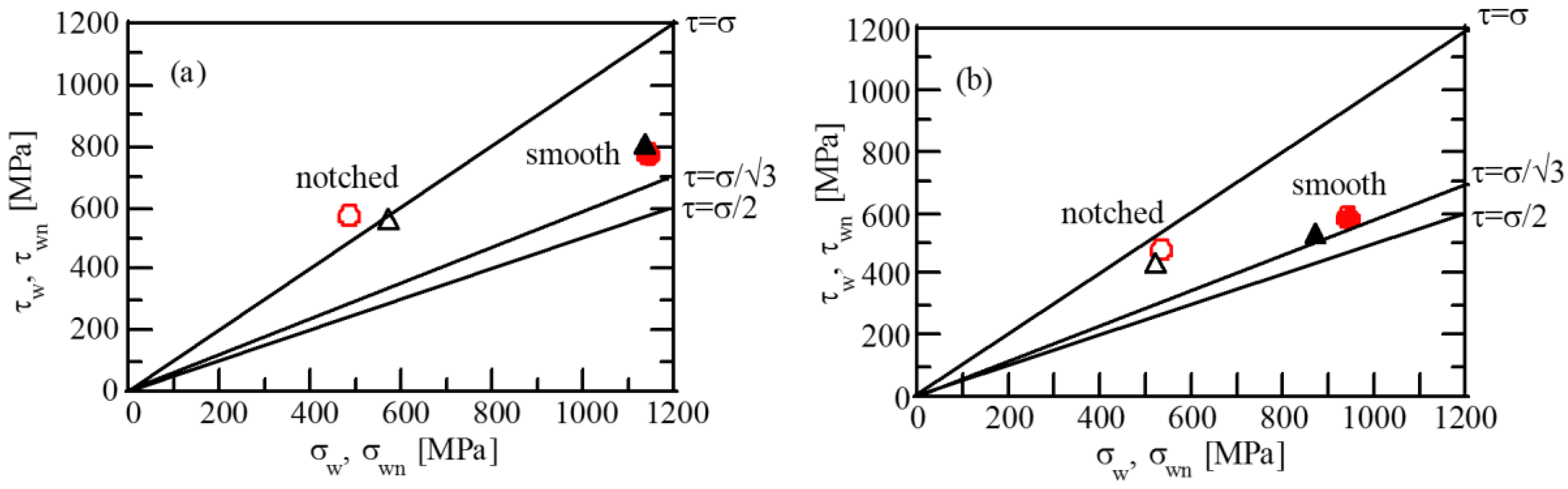
Figure 10.
Crack initiation origins and the distribution of surface-hardened layer properties in TM steel subjected to vacuum carburization and subsequent fine particle peening. (a) surface crack, (b) fish-eye crack. HV: Vickers hardness, σX,α: residual stress in α-bcc phase, fγ: volume fraction of untransformed retained austenite, Δfαm: volume fraction of strain-induced martensite.

Figure 11.
Variations in (a) torsional (τw, τwn) and (b) rotational bending fatigue limits (σw, σwn) for smooth and notched specimens as a function of the sum of estimated yield stress and absolute value of maximum compressive residual stress {σY,est + abs(σXα,max)} in TM (●○) and SNCM420 (▲△) steels subjected to vacuum carburization and subsequent fine particle peening (●▲, thick lines ) and heat-treatment and subsequent fine particle peening (○△, thin lines).
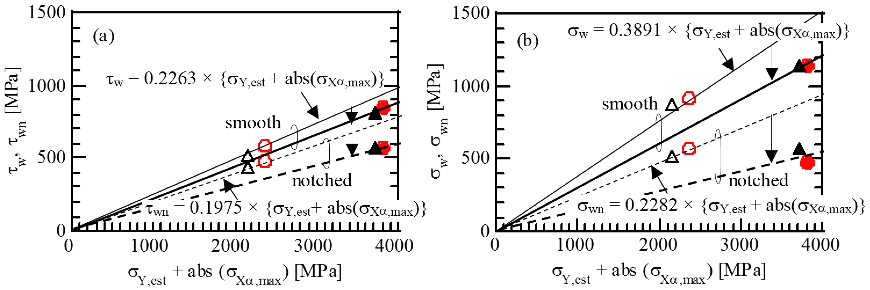
Figure 12.
Variations of (a) volume fraction of retained austenite (fγ), (b) Vickers hardness (HV), and (c) residual stress (σXα) as a function of depth from surface (ds) in TM (●○) steel subjected to vacuum carburization and fine particle peening (VC + FPP). Solid and open marks represent before and after rotary bending fatigue tests, respectively. Gray marks (●) denote the properties of as-vacuum-carburized TM steel (VC).


Table 1.
Chemical composition [mass%] of the steels used.
| Steel | C | Si | Mn | P | S | Cr | Mo | Ni | Nb | Al | N |
|---|---|---|---|---|---|---|---|---|---|---|---|
| TM | 0.20 | 1.50 | 1.51 | 0.005 | 0.002 | 1.00 | 0.01 | 0.02 | 0.05 | 0.039 | 0.0009 |
| SNCM420 | 0.20 | 0.20 | 0.50 | 0.009 | 0.013 | 0.55 | 0.15 | 1.68 | 0.00 | - | - |
Table 2.
Fine particle peening conditions.
| Shot Material | Steel |
|---|---|
| Shot Vicker Hardness | 697–832 |
| Shot Diameter [µm] | 70 |
| Pressure [MPa] | 0.26 |
| Pressure Mode | Air Nozzle |
| Arc Height [mm (N)] | 0.104 |
| Coverage [%] | 300 |
Table 3.
Properties on the surface and in the surface-hardened layer and tensile properties of TM and SNCM420 steels subjected to various process.
Table 3.
Properties on the surface and in the surface-hardened layer and tensile properties of TM and SNCM420 steels subjected to various process.
| Steel | Condition | RZ | fγ,max | HVmax | σXα,max | TS | TSN | NSR | El | RA |
|---|---|---|---|---|---|---|---|---|---|---|
| TM | VC | 3.0 | 20.5 | 745 | −97 | 1576 | 1038 | 0.66 | 0.50 | 3.0 |
| VC + FPP | 3.9 | 16.5 | 772 | −1425 | 1669 | 1509 | 0.90 | 0.87 | 1.6 | |
| SNCM 420 | VC | 3.3 | 16.3 | 725 | −123 | 1295 | 1076 | 0.83 | 0.12 | 1.8 |
| VC + FPP | 3.9 | 13.5 | 743 | −1414 | 1745 | 1297 | 0.74 | 1.30 | 1.9 |
VC: vacuum carburizing; FPP: fine particle peening; RZ [mm]: maximum roughness height; fγ,max [vol.%]: maximum volume fraction of untransformed retained austenite; HVmax: maximum Vickers hardness; σXα,max [MPa]: maximum residual stress of α-bcc phase; TS [MPa]: tensile strength; TSN [MPa]: notch tensile strength; NSR (=TSN/TS): notch strength ratio; El [%]: total elongation; RA [%]: reduction of area.
Table 4.
Numbers of cycles to fracture (Nf [cycle]) in vacuum-carburized and subsequently fine particle peened TM and SNCM420 steels tested at various (a) nominal shear stress amplitudes (τa [MPa]) and (b) nominal rotational bending stress amplitudes (σa [MPa]).
Table 4.
Numbers of cycles to fracture (Nf [cycle]) in vacuum-carburized and subsequently fine particle peened TM and SNCM420 steels tested at various (a) nominal shear stress amplitudes (τa [MPa]) and (b) nominal rotational bending stress amplitudes (σa [MPa]).
| (a) | Specimen | Smooth | Notched | ||||||
| τa | Nf | τa | Nf | ||||||
| TM | 736 | 1.00 × 10⁷ | 572 | 1.00 × 10⁷ | |||||
| 855 | 1.00 × 10⁷ | 600 | 6.59 × 10⁵ | ||||||
| 855 | 7.18 × 10⁶ | 637 | 1.67 × 10⁶ | ||||||
| 962 | 4.94 × 10⁶ | 678 | 1.27 × 10⁶ | ||||||
| 1022 | 4.56 × 10⁵ | 744 | 2.77 × 10⁵ | ||||||
| 1064 | 2.50 × 10⁵ | 786 | 1.20 × 10⁵ | ||||||
| 1129 | 4.21 × 10⁴ | 842 | 5.41 × 10⁴ | ||||||
| 976 | 2.80 × 10³ | ||||||||
| SNCM420 | 807 | 1.00 × 10⁷ | 565 | 1.00 × 10⁷ | |||||
| 962 | 1.27 × 10⁶ | 573 | 9.26 × 10⁶ | ||||||
| 986 | 3.30 × 10⁶ | 600 | 2.75 × 10⁶ | ||||||
| 1063 | 6.83 × 10⁵ | 637 | 2.60 × 10⁵ | ||||||
| 1123 | 1.76 × 10⁵ | 714 | 8.02 × 10⁴ | ||||||
| (b) | Specimen | Smooth | Notched | ||||||
| σa | Nf | σa | Nf | ||||||
| TM | 1143 | 1.00 × 10⁷ | 485 | 1.00 × 10⁷ | |||||
| 1225 | 2.13 × 10⁶ | 556 | 2.41 × 10⁶ | ||||||
| 1307 | 9.87 × 10⁵ | 565 | 1.26 × 10⁶ | ||||||
| 1455 | 8.05 × 10⁴ | 571 | 6.71 × 10⁵ | ||||||
| 1547 | 3.09 × 10⁵ | 648 | 1.35 × 10⁴ | ||||||
| 1700 | 1.10 × 10⁴ | 651 | 2.89 × 10⁴ | ||||||
| SNCM420 | 1139 | 1.00 × 10⁷ | 570 | 1.00 × 10⁷ | |||||
| 1219 | 8.31 × 10⁶ | 591 | 4.80 × 10⁵ | ||||||
| 1298 | 6.06 × 10⁵ | 608 | 2.27 × 10⁵ | ||||||
| 1466 | 2.43 × 10⁵ | 652 | 2.46 × 10⁴ | ||||||
| 1539 | 2.31 × 10⁴ | 674 | 3.11 × 10⁴ | ||||||
| 1700 | 4.67 × 10³ | 732 | 6.57 × 10³ | ||||||
Table 5.
Fatigue properties of TM and SNCM420 steels subjected to various processes.
| Steel | Process | τw | τwn | qt | σw | σwn | qb |
|---|---|---|---|---|---|---|---|
| TM | HT | 404 | 364 | 0.18 | 675 | 381 | 0.86 |
| HT+FPP | 582 | 481 | 0.35 | 919 | 572 | 0.67 | |
| VC | 654 | 498 | 0.52 | 703 | 320 | 1.32 | |
| VC+FPP | 855 | 572 | 0.82 | 1143 | 485 | 1.51 | |
| SNCM 420 | HT | 366 | 358 | 0.03 | 586 | 378 | 0.61 |
| HT+FPP | 518 | 434 | 0.32 | 872 | 521 | 0.75 | |
| VC | 628 | 461 | 0.60 | 803 | 481 | 0.74 | |
| VC+FPP | 807 | 565 | 0.71 | 1139 | 570 | 1.11 |
HT: heat-treating; FPP: fine particle peening; VC: vacuum-carburizing; τw, τwn [MPa]: torsional fatigue limits of smooth and notched specimens, respectively; qt: notch sensitivity factor for torsion, = {(τw/τwn) − 1}/(Kt − 1); Kt: stress concentration factor in torsion = 1.6; σw, σwn [MPa]: rotational bending fatigue limits of smooth and notched specimens, respectively; qb: notch sensitivity factor in bending, = {(σw/σwn) − 1}/(Kb − 1); Kb: stress concentration factor for bending, =1.9.
© 2017 by the authors. Licensee MDPI, Basel, Switzerland. This article is an open access article distributed under the terms and conditions of the Creative Commons Attribution (CC BY) license (http://creativecommons.org/licenses/by/4.0/).
Share and Cite
MDPI and ACS Style
Sugimoto, K.-i.; Hojo, T.; Mizuno, Y. Torsional Fatigue Strength of Newly Developed Case Hardening TRIP-Aided Steel. Metals 2017, 7, 375. https://doi.org/10.3390/met7090375
AMA Style
Sugimoto K-i, Hojo T, Mizuno Y. Torsional Fatigue Strength of Newly Developed Case Hardening TRIP-Aided Steel. Metals. 2017; 7(9):375. https://doi.org/10.3390/met7090375
Chicago/Turabian StyleSugimoto, Koh-ichi, Tomohiko Hojo, and Yuta Mizuno. 2017. "Torsional Fatigue Strength of Newly Developed Case Hardening TRIP-Aided Steel" Metals 7, no. 9: 375. https://doi.org/10.3390/met7090375
Note that from the first issue of 2016, this journal uses article numbers instead of page numbers. See further details here.