Effect of Computational Parameters on Springback Prediction by Numerical Simulation


1
Depertment of Materials Forming and Processing, Rzeszow University of Technology, Al. Powst. Warszawy 8, 35-959 Rzeszow, Poland
2
Department of Mechanical and Structural Engineering, University of Stavanger, N-4036 Stavanger, Norway
*
Author to whom correspondence should be addressed.
Metals 2017, 7(9), 380; https://doi.org/10.3390/met7090380
Submission received: 27 August 2017
/
Revised: 14 September 2017
/
Accepted: 15 September 2017
/
Published: 19 September 2017
(This article belongs to the Special Issue Advances in Plastic Forming of Metals)
Abstract
:Elastic recovery of the material, called springback, is one of the problems in sheet metal forming of drawpieces, especially with a complex shape. The springback can be influenced by various technological, geometrical, and material parameters. In this paper the results of experimental testing and numerical study are presented. The experiments are conducted on DC04 steel sheets, commonly used in the automotive industry. The numerical analysis of V-die air bending tests is carried out with the finite element method (FEM)-based ABAQUS/Standard 2016 program. A quadratic Hill anisotropic yield criterion is compared with an isotropic material described by the von Mises yield criterion. The effect of a number of integration points and integration rules on the springback amount and computation time is also considered. Two integration rules available in ABAQUS: the Gauss’ integration rule and Simpson’s integration rule are considered. The effect of sample orientation according to the sheet rolling direction and friction contact behaviour on the prediction of springback is also analysed. It is observed that the width of the sample bend in the V-bending test influences the stress-state in the cross-section of the sample. Different stress-states in the sample bend of the V-shaped die cause that the sheet undergoes springback in different planes. Friction contact phenomena slightly influences the springback behaviour.
1. Introduction
Bending is one of the sheet forming methods and is a plastic deformation of the material subjected to bending moment. Plastic forming of the sheets requires, at the design stage of manufacturing, taking into account specific properties of the sheet material, i.e., Young’s modulus, yield stress, ratio of yield stress to ultimate tensile stress, and microstructure of the material [1]. The non-uniform strain state at the section of bent material leads to existence of residual stress after load releasing. This stress produces springback which is manifested by unintended changes in the shape of the element after forming. The measure of the springback value is a springback coefficient or angle of springback. The value of springback coefficient depends on, among others, the value of angle and radius of bending, thickness and width of the sheet strip, the mechanical properties of the sheet material, the temperature of bending process, and strain rate [1]. The investigations of Caden et al. [2] proved the effect of coefficient of friction on the springback amount.
Elastic recovery of material is one of the main sources of shape and dimensional accuracy of drawpieces. Springback cannot be eliminated, but there are a few methods to minimize elastic return of the stamped part due to elastic recovery of sheet metal after forming. One of the methods is a suitable design of the die which takes into consideration the amount of springback. Furthermore, the change in selected bending process parameters can minimize the springback. The idea of correction of the die shape consists in additional overbending of the material [3]. Among the many advanced methods of predicting the final shape of the drawpiece, the finite element method (FEM) is the most often used [4]. FEM is the main technique used to simulate sheet metal forming processes in order to determine the distribution of stresses and deformations in the material, forming forces and potential locations of the defects.
For simple problems analytical methods for bending process analysis may be used. Due to the assumed simplifications, however, the analytical methods are not sufficiently general to accommodate the material and the geometrical influences [5]. Although, the experiments are time-consuming, they are still needed to better understand the elastic deformations of materials. To study the springback of sheet metals, several forms of experimental tests are used, including U-bending [1], V-bending [6], cylindrical bending, three-point bending, rotary bending, and flanging. Karağaç [7] estimated springback by using fuzzy logic based on the results of the V-bending test conducted at different holding times and bending angles. Leu and Hsieh [8] explored the influence of the coining force on the spring-back reduction in the V-die bending process. The effects of various process parameters, including the material anisotropy and coefficient of friction, on the spring-back reduction were confirmed. Bakhshi-Jooybari et al. [9] investigated the effects of significant parameters on spring-back in U-die and V-die bending of anisotropic steel sheet. Based on the comparison of experimental results with the numerical ones it was found that the bending angle to the rolling direction will influence the spring-back, where the greater the angle to the rolling direction, the greater the springback.
Results of study on the effect of the speed of deformation on the spring value of the sheet springback have been discussed by Firat et al. [10]. Hang and Leu [11] conducted experimental studies for steel sheets and presented the impact of variable process parameters such as the radius of the punch, die radius, punch speed, friction coefficient, and normal anisotropy on the sheet springback amount during the V-bending process. Garcia-Romeu et al. [12] conducted bending experiments on aluminium and stainless steel sheets for analysis of effects of bending angle on springback. Ragai et al. [13] presented experimental and numerical results of the anisotropy of the mechanical properties of stainless steel 410 sheet metal on springback. Vin et al. [14] investigated the effect of Young’s modulus on the springback in the air V-bending process. Thipprakmas and Rojananan [15] examined the springback and spring-go phenomena on the V-bending process using the finite element method (FEM). Tekiner [16] examined the effect of bending angle on springback of six types of materials with different thicknesses in V-die bending.
The springback phenomenon of the sheets is also affected by the accuracy of manufacturing the stamping dies. Lingbeek et al. [17] presented a method for springback compensation in the tools for sheet metal products, concluding that for industrial deep drawing products the accuracy of the results has not yet reached an acceptable level. Del Pozo et al. [18] presented a method for the reduction of both the try-out and lead-time of complex dies. Furthermore, López de Lacalle [19] concluded that the two main problems have to be overcome in high-speed finishing of forming tools. The first problem is the simultaneous finishing of surfaces with different hardness in the same operation and with the same computer numerical control (CNC) program; and the second one is the unacceptable dimensional error resulting from tool deflection due to cutting forces.
Taking into account the numerical strength of the deformation of the sheet metal, it was possible to improve the convergence of experimental and simulation results, indicating the validity of the Bauschinger effect in simulating the springback problem. In addition to the Bauschinger effect, the elastic stress-strain relation is also important behaviour, especially given that springback is an elastic recovery phenomenon [20]. Experiments by Yoshida et al. [21] were carried out on how to utilize reverse bending that takes place in the forming process, how to improve uneven stress by applying a stress in sheet thickness direction, and how to reduce the plastic strain of a die shoulder without applying blankholder force thus to study the influences of those methods on springback. Besides elastic behaviour of material, the plastic anisotropic properties of material and hardening rule have to be taken into consideration in FEM analysis of springback. The isotropic hardening model and the kinematic hardening model are widely used in FEM analysis of sheet metal forming. While the former model can describe hardening, the latter, on the other hand, can describe the Bauschinger effect qualitatively, but cannot describe hardening [22]. To model the Bauschinger effect, several other models have been proposed [23].
To reflect the nonlinear strain and stress during elastic-plastic deformation of the sheet material, the crucial point in the computational modelling of springback is the proper choice of finite element formulation, the element size and a number of integration points through the sheet thickness. Suitable mesh density, especially in the region of contact of the tools with the sheet is a balance between computational time and springback prediction accuracy. Many publications deal with the determination of the optimal number of integration points through the sheet thickness and the proposed number of integrations points varies from 5 to 51. In the case of non-linear analysis, five integration points are sufficient to provide accurate results [24], while Xu et al. [25] concluded that usually seven integration points are sufficient. On the contrary, Wagoner and Li [26] found that to analyse the springback with 1% computational error, up to 51 points are required for shell type elements. Thus, as noticed by Banabic [27], the choice of a number of integration points is still an open issue in the simulation of springback.
The aim of this paper is investigation of the effect of some numerical approaches on prediction accuracy of the springback phenomenon. Experimental and numerical investigations of springback were carried out in V-bending test. Finite element (FE) elastic-plastic model of V-bending is built in ABAQUS software (Dassault Systèmes Simulia Corp., Providence, RI, USA). The numerical analyses took into account the sample orientation, material anisotropy, and work hardening phenomenon. Furthermore, the number of integration points and sensitivity to the friction coefficient are considered.
2. Materials and Methods
The experiments are conducted on DC04 steel sheets of 2 mm thickness cut along the rolling direction of the sheet and transverse to the rolling direction. To characterize the material properties, specimens for uniaxial tensile test steel sheets were cut at different orientations to the rolling directions (0°, 45°, and 90°). Three specimens were tested for each direction and average value of basic mechanical parameters (Table 1) were determined using the formula:
where X is the mechanical parameter, and the subscripts denote the orientation of the sample with respect to the rolling direction of sheet.
The representative true stress vs. true strain relations for three analysed sample cut directions are presented in Figure 1. The tested sheets are cold rolled, so the manufacturing process induces a particular anisotropy characterised by the symmetry of the mechanical properties with respect to three orthogonal planes. Furthermore, the method of trimming technology of standard sheet-type tensile test specimens can influence the surface state of the specimen. However, tensile tests of the sample prepared using milling, abrasive water jet, punching, wire electro discharge machining, and milling conducted by Martínez Krahmer et al. [27] show that some changes on the surface state appeared, but the effect on tensile strength was lower than 5%.
The anisotropy of plastic behaviour of sheet metals is characterized by the Lankford’s coefficient r, which is determined using the formula:
where w0 and w are the initial and final widths, while l0 and l are the initial and final gage lengths, respectively.
If the value of r-coefficient is greater than 1, the width strains are dominant, which is a characteristic of isotropic materials. On the other hand, a value of r < 1 indicates that the thickness strains will dominate.
The values of the parameters C and n in Hollomon equation [28] were determined from the logarithmic true stress-true strain plot by linear regression. The mean value of n exponent for the whole range of strain is usually assumed in numerical simulations. The strain hardening exponent can be determined using following formula:
The average values of Lankford’s r-coefficient for different directions in the plane of sheet metal represent the average coefficient of normal anisotropy
Hovewer, the variation of the normal anisotropy with the angle to the rolling direction is given by the coefficient of planar anisotropy Δr. For the tested sheets Δr = 0.67, which indicates existence of material flow in 0° and 90° directions. In other words, if the value of Δr is positive then ears are formed in the direction of sheet rolling and in the direction perpendicular to rolling direction.
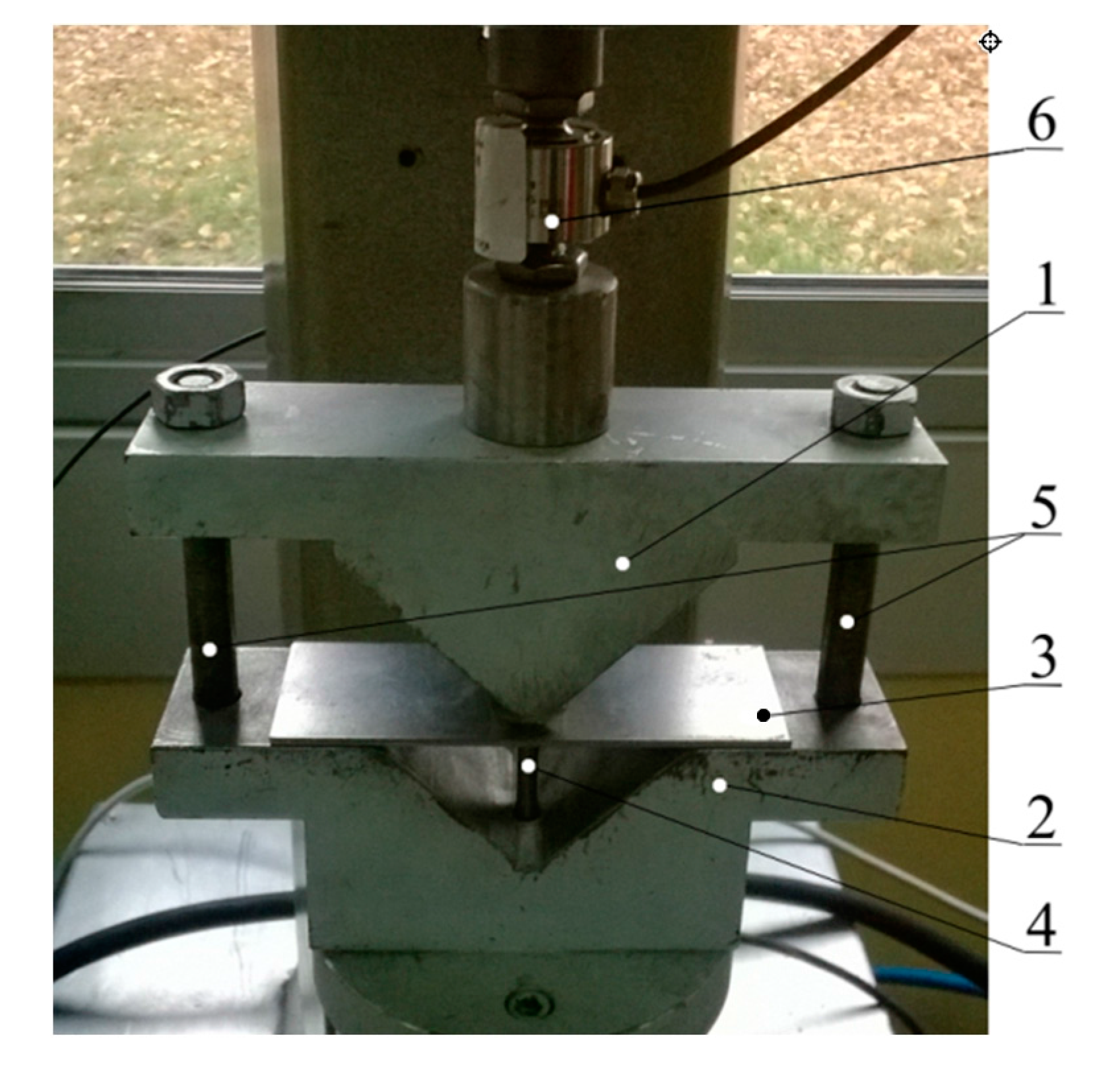
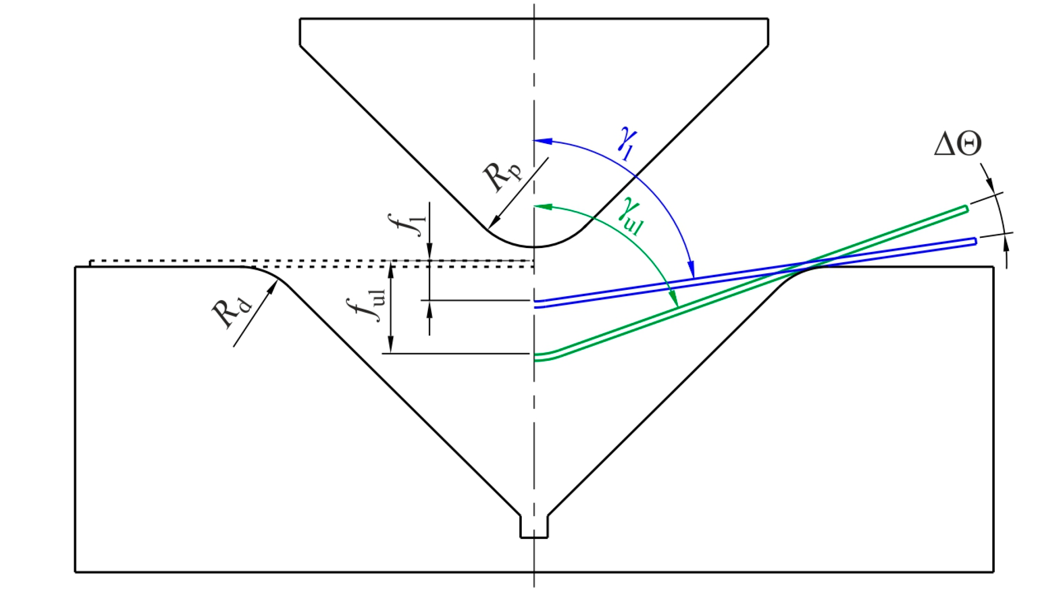
Air bending experiments were carried out in a designed semi closed 90° V-shaped die (Figure 2). Bending tests were carried out on rectangular samples of dimension 20 × 110 mm2. The die assembly consists of a die with Rd = 10 mm rounded edge, and a punch with a nose radius of Rs = 10 mm. During the tests, punch bend depth under loading fl and punch bend depth under unloading ful (Figure 3) were measured. The values of these parameters were registered by the QuantumX Assistant V.1.1 program (V.1.1, Hottinger Baldwin Messtechnik GmbH, Darmstadt, Germany, 2011) for processing the signals of both force and punch stroke transducers. To measure the bending force, the HBM U9B force transducer (Hottinger Baldwin Messtechnik GmbH, Darmstadt, Germany) with nominal force 5 kN is used. The amount of springback was then evaluated as:
where ful is the punch bend depth under unloading and fl is the punch bend depth under loading (Figure 3).
The other coefficient which may be used to analyse springback is defined as:
where γl is the bend angle under loading and γul is the bend angle under unloading (Figure 3).
Three bending tests were conducted for all punch depths under loading and then the average value of springback was evaluated.
3. Numerical Model
The springback computations were conducted using ABAQUS/Standard 3D Experience® 2016 HF2 (2016 HF2, Dassault Systèmes Simulia Corp., Providence, RI, USA, 2016) which is used in springback prediction [29]. The numerical model of the problem (Figure 4) corresponds to the experimental set-up shown in Figure 2. The blank was modelled with an eight-node quadratic, doubly curved shell elements S8R [30]. The analytical discrete rigid tools are meshed using four-node 3D bilinear rigid quadrilateral R3D4 elements. The meshed model of the tools consists of 9586 elements.
The elastic behaviour of the sheet metal is specified in the numerical simulations by the value of Young’s modulus, E = 210 GPa, and of Poisson’s ratio ν = 0.3. The sheet material density is set to 7860 kg/m3.
In the numerical model, the anisotropy of the material has been established using Hill (1948) [31] yield criterion (Equation (6)) with strain hardening behaviour that uses Hollomon power-type law [29]:
where is the equivalent stress, and indices 1, 2, 3 represent the rolling, transverse, and normal direction to the sheet surface. Constants F, G, H, L, M, and N define the anisotropy state of the material and can be computed based on Lankford’s coefficients [31]. The major advantage of the Hill (1948) function is that it gives an accurate description of yielding of steel sheets [32]. To investigate the effect of material model on the deformation of the sample material in the width direction, the isotropic material behaviour described by von Mises [33] yield criterion is also considered. For ideal case of isotropic materials, von Mises yield condition is expressed as:
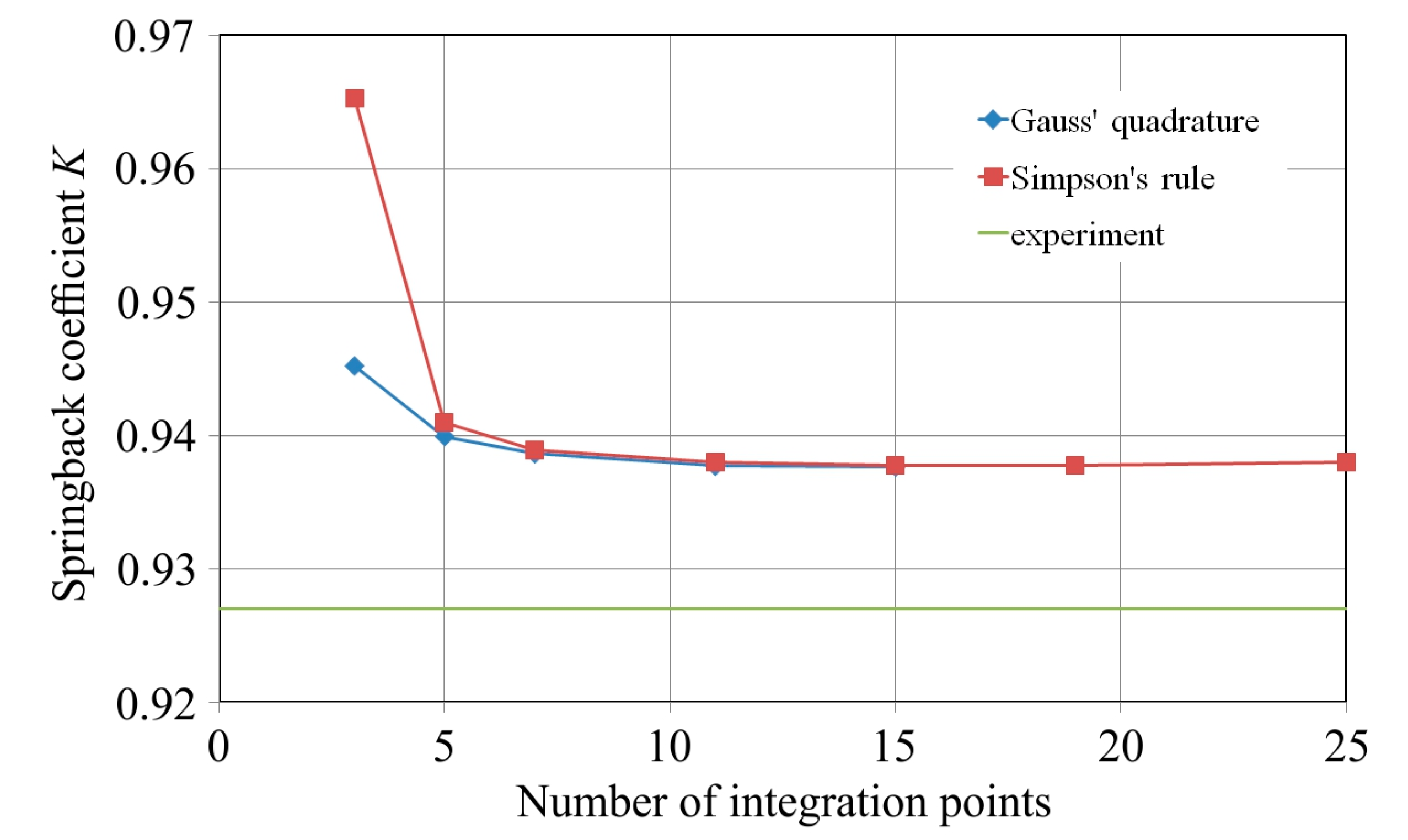
The shell elements integrated in ABAQUS must be assigned with a method of integration rule and a number of integration points through the sheet thickness. Two integration rules available in ABAQUS—the Gauss’ integration rule and Simpson’s integration rule—are analysed in this paper. The number of integration points must be odd in order that one point can be in the middle surface of the shell element [24]. In order to study how the number of integration points influence springback prediction and computation time, the integration points 3, 5, 7, 11, 15, 19, and 25 were analysed in the case of Simpson’s rule. Due to upper limits of the integration points in Gauss’ rule built in ABAQUS, the simulations were carried out for the range of integration points from 3 to 15.
In addition to the number of integration points, the size of the shell elements is a critical parameter that influences the accuracy of computations especially in the bending process where the curvature of the sheet material has to be accurately represented. The optimum elements size may be determined based on the results of mesh sensitivity analysis. Such analysis with identical geometry of the sheet material and tool has been previously reported [6] by the authors of this paper. To determine an optimal mesh size, the numerical analyses were carried out for four selected meshes that resulted in the number of elements: 84, 280, 1120, and 4400. Furthermore, the sensitivity analysis of the mesh size was done for four punch strokes fl: 3, 6, 12, and 18 mm. It was found that the increase in the number of elements stabilizes the springback measured as the difference between punch bend depth under loading fl and unloading ful:
The criterion to assess the effect of the number of elements on springback, prediction of accuracy of the absolute mean error is assumed:
where i is the level of punch stroke i = 1, 2, 3, and 4 corresponding to punch strokes 3 mm, 6 mm, 12 mm, and 18 mm, respectively.
The absolute mean error value for all analysed punch strokes fg is equal to 2.64% (after increasing number of elements from 84 to 280), 2.56% (from 280 to 1120), and 1.14% (from 1120 to 4400). In this study, the accepted value is assumed to be 1.5% and, hence, the number of elements 1120 is acceptable in the conducted numerical models.
The contact between the assumed rigid bodies (the die and punch) and the deforming workpiece was defined by the penalty method [30]. To study the effect of the number of integration points, material model and sample orientation, the friction coefficient between the sheet metal and tools was assumed to be 0.01 [34]. However, in the numerical analyses of the effect of the friction coefficient value on the springback behaviour, five friction coefficient values (0.01, 0.03, 0.06, 0.1, 0.2) were considered.
4. Results
4.1. Effect of the Number of Integration Points
The number of integration points is a significant parameter for springback simulation using shell elements. The effect of a number of integration points on the computational time and springback coefficient K is presented in Figure 5 and Figure 6, respectively. The change in computational time is evaluated for a reference time of computation of the numerical model of the sheet with the Gauss integration rule and five integration points through the thickness. For these conditions, which are recommended by many authors in the non-linear analysis of homogeneous shells [24], the computational time takes about 14 min on a standard personal computer (HDD SSD, 32 GB RAM, i7-6700HQ [email protected] GHz, AsusTek Computer Inc., Taipei, Taiwan). As observed, the lowest computation time is for both integration rules for the five integration points (Figure 5).
A further increase in the number of integration points through the sheet thickness results in greater time consumption. In the case of the analysed model, the computation time is not very long, but it can be speculated that if the number of elements increases the computation time increases exponentially.
A higher number of integration points results in a decrease of the predicted springback coefficient (Figure 6). When the number of integration points is over 11, the value of the computation time is stabilised. This relation is observed for both the analysed integration rules. It can be concluded that after increasing 19 integration points, the computation time notably increases (Figure 5), however, no further improvement in springback coefficient is observed (Figure 6). In summary, five integration points are the minimum acceptable, considering the computation time and accurateness of springback prediction. The Gauss’ rule with five integration points gives better prediction of the springback coefficient, which is in good agreement with the results of Burgoyne and Crisfield [35] and Wagoner and Lee [26]. In the case of Gauss quadrature, an increase of the number of integration points from five to 15 decreases the springback prediction error at 0.24%. However, the computation time increases to 40%. A similar conclusion can be drawn for Simpson’s rule. After exceeding seven integration points through the sheet thickness, both rules give similar results (Figure 6). It is well known that if a sheet undergoes plastic deformation in the bending process, points of discontinuity appear in the stress distribution and the number of necessary integration points increases with an increase of the bending radius (depth of punch).
In fact, when material is in an elastic regime, then the stress distribution through the sheet thickness is linear and the number of integration points can be limited. However, when sheet material undergoes the elastic-plastic behaviour, to fit better the nonlinear stress distribution, the required number of integration points must be increased. It can be speculated that a number of integration points depend mainly on the bending radius and the ratio of the inside radius of the bend to material thickness.
4.2. Sample Orientation
The change of the springback coefficient Kγ as a function of the bending angle under loading for samples cut along the rolling direction and transverse to this direction are presented in Figure 7a,b, respectively. According to Equation (4), high springback of the material denotes the lower values of the springback coefficient Kγ. As can be observed in Figure 7b, the samples cut transverse to the rolling direction exhibit lower values of springback coefficient. The relation of springback coefficient for both analysed orientations is almost linear. In all cases, the predicted value of the springback coefficient is higher than the measured ones. The differences in the Kγ value between experimental and numerical results decrease with the increasing bending angle under loading γl. The difference in the value of springback for the analysed perpendicular orientations is due to crystallographic structure of the sheet material. The cold rolling of the sheets produces the directional change in the deformation of material microstructure, i.e., the grains are elongated in the direction of the cold rolling process. Thus, the material withstands bending according to rolling direction (orientation 0° in Figure 4). Furthermore, in the case of rolling direction, the grains are only subjected to tensile or bending stresses, but in the case of transverse direction, a significant size of deformation energy is used to change the orientation of grains [36].
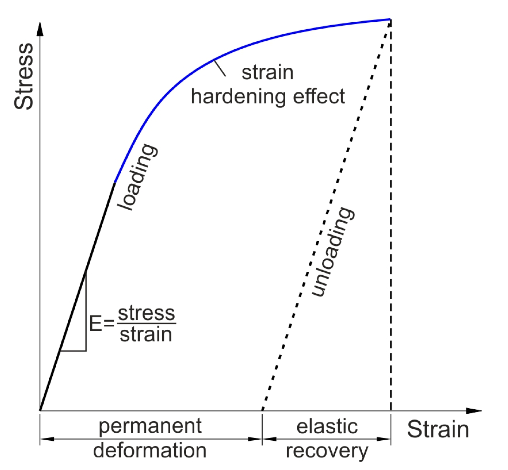
During bending of the sheet strip, the outside side of sheet material under the rounded edge of the punch is subjected to elastic stress (Figure 8). If the load reaches the yield point the specimen undergoes plastic deformation and strain hardening phenomenon. Plastic deformation, after unloading, is followed by elastic recovery upon removal of the load. The slope of unloading line is parallel to the elastic characteristics during loading. The inside part of the sheet strip under the rounded edge of the punch is compressed.
4.3. Sheet Deformation during Bending
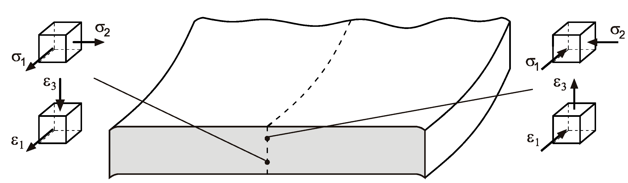
The large sample width compared to the thickness determines the occurrence of a specific stress state in the sample (Figure 9). It is clear from this figure that in this section of the sample, there is a neutral interlayer on which the sign of the deformation changes. In the middle part of the sample width on the inner side, the longitudinal stresses are compressive and the deformation is negative, and on the external side, the longitudinal stress is negative and the deformation is positive (Figure 9). This phenomenon is, however, disturbed at the edge of the sheet.
In general, if the sheet width is much larger than the sheet thickness, the width of the sheet is not changed during bending. If the ratio of the sheet width to the sheet thickness is lower than 4, the rectangular section of the sheet is changed to a trapezoidal section. At the inner side of the bending curvature the width of the sample increases. The situation at the outer side is the contrary, i.e., the sheet width is reduced.
The numerically-determined deviation of the sample profile at sample width direction is presented in Figure 10. This deviation is evaluated at the middle layer of the shell elements. The profile deviation does not depend on the material description and sample orientation. Thus, the character of the profile deviation in all cases is identical. The presented phenomenon of dependence of the sample width on the stress-state in the sample material is rarely investigated by researchers who studied the springback phenomenon. The different stress-state in the sample bend in V-shaped die causes the sheet to undergo springback in different planes.
Springback intensity is influenced by the orientation of the sample in terms of symmetric plane of the punch. It is conceivable that sample orientation in the rolling direction produces variations of the elastic-plastic properties of the sheet metal and residual stress after sample unloading (Figure 11). The distribution of HMH (Huber-Mises-Hencky) stress (Figure 11) along the sheet width direction in the lower part of sample that gets contact with the punch is related to the distribution of sample profile deviation (Figure 10). The lowest values of the HMH stress are observed in the vicinity of the sample edge (Figure 11, right).
4.4. Effect of Friction Coefficient
The effect of friction coefficient on springback phenomenon is studied for both sample orientations and three bend angles under loading that corresponds to punch bend depths under loading fl: 6 mm, 12 mm, 18 mm, and 24 mm. The results indicate that the value of coefficient of friction in small scale influences the springback coefficient Kγ (Figure 12). The difference in angle γl for all used friction coefficients does not exceed 0.4%. However, increasing of coefficient of friction value causes slight decrease in springback angle under unloading γul. Similar results were found for the 90° sample orientation.
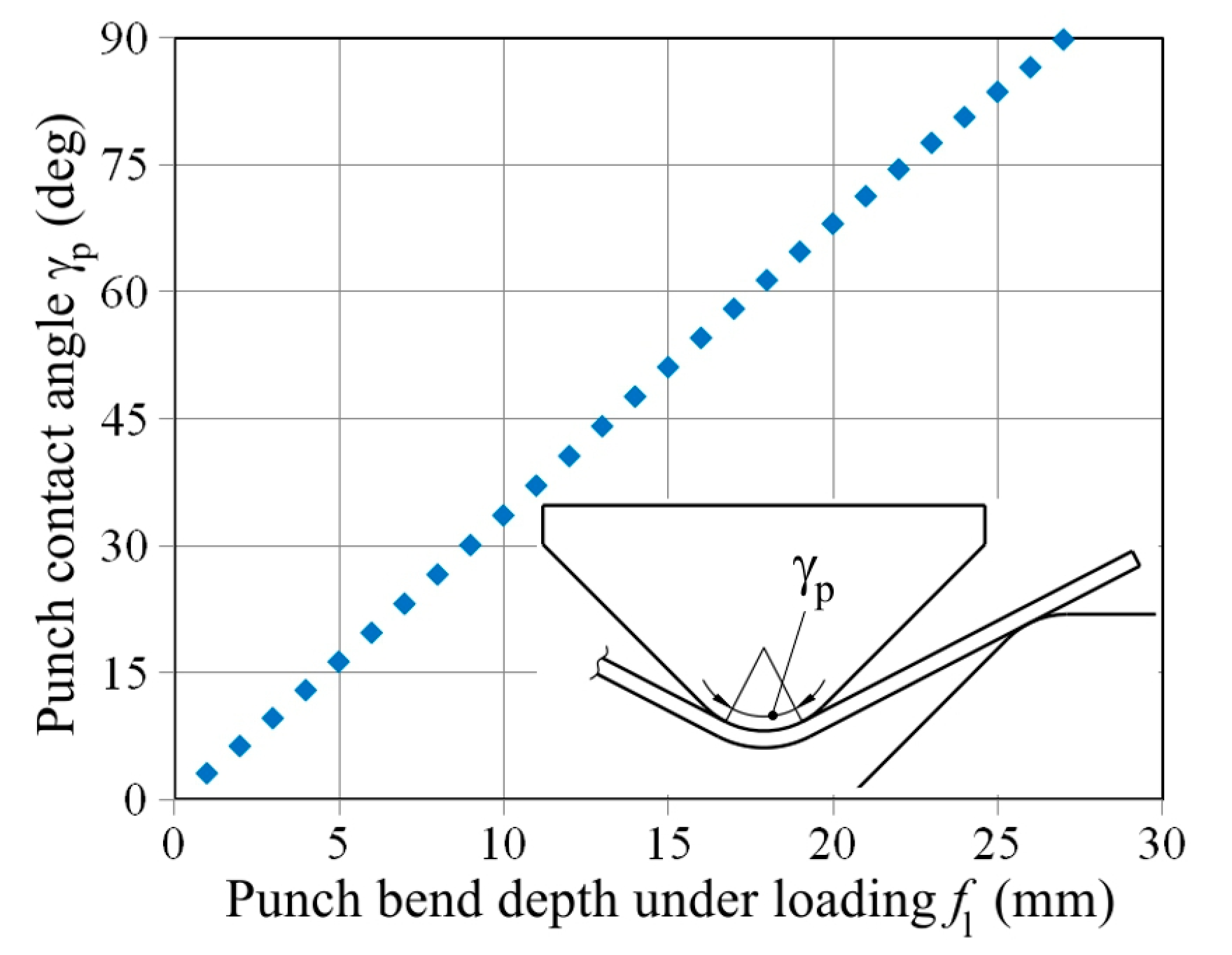
Based on conducted numerical investigations, it can be concluded that the friction coefficient slightly influences the springback phenomenon in V-die air bending test. In this test, the contact between the punch and sample is linear in a large distance during punch displacement. Only at final punch depths does the area of contact increase quickly. The geometrical analysis shown in Figure 13 shows that the relation between the punch contact angle and punch depth is linear. Furthermore, linear contact exists between the sheet and samples at the rounded edge of the die, so the friction coefficient slightly influences the springback amount. The friction coefficient is different on the curved and flat parts of both die and punch, and it is very difficult to measure this coefficient experimentally. Thus, in modelling bending tests, the constant friction coefficient value is usually assumed [34,37]. The coefficient of friction is an important factor in processes of sheet metal forming, such as deep drawing, where there exists great mutual displacements in the sheet-tool interface and high changes in surface topography due to plastic deformation of the workpiece. The small effect of changes in friction coefficient on springback amount may be a result of the used elements. The shell element represents the sheet mid-plane. However, bending causes the highest amount of plastic deformation in the extreme fibres of the sheet. The accuracy of contact prediction depends on the number of integration points. Due to the small area of contact between rounded tools and the sheet, the sensitivity of the friction coefficient on the contacting surface on the numerical results of shell elements is smaller than in the case of brick elements. In the case of both elements, the dimensions of the element should be as proportional as possible. However, the usage of many brick elements through the thickness may guarantee the lower element size in contacting surfaces, and a better area of contact prediction.
5. Conclusions
The study of the influence of computational parameters on the springback phenomenon of sheet metals is presented in this article. Samples cut along the rolling direction and transverse to the rolling directions are employed. Experimental tests with identical geometry and parameters are conducted to compare with the numerical simulation results.
The main conclusions drawn from experimental and numerical analyses are as follows:
- The samples cut along the transverse direction exhibit greater springback than the blank cut in the rolling direction.
- The variation of the springback coefficient value almost shows linear dependence between the springback coefficient value and bend angle under loading.
- The results of the numerical model indicate that five integration points are the minimum acceptable considering the computation time and accuracy of springback prediction.
- Analyses of the sheet material with seven or more integration points through the thickness indicated that both Simpson’s and Gauss’ rules provide similar accuracy of prediction.
- The Gauss’ rule with five integration points is optimal to obtain the accurate results of springback prediction.
- The friction coefficient value slightly influences the springback amounts.
Author Contributions
Tomasz Trzepieciński conceived and designed the experiments; Hirpa G. Lemu performed the review of literature and established the assumptions for numerical modelling; and both authors contributed equally to writing the paper and numerical modelling.
Conflicts of Interest
The authors declare no conflict of interest.
References
- Dai, H.L.; Jiang, H.J.; Dai, T.; Xu, W.L.; Luo, A.H. Investigation on the influence of damage to springback of U-shape HSLA steel plates. J. Alloys Compd. 2017, 708, 575–586. [Google Scholar] [CrossRef]
- Carden, W.D.; Geng, L.M.; Matlock, D.K.; Wagoner, R.H. Measurement of springback. Int. J. Mech. Sci. 2002, 44, 79–101. [Google Scholar] [CrossRef]
- Yang, X.A.; Ruan, F. A die design method for springback compensation based on displacement adjustment. Int. J. Mech. Sci. 2011, 53, 399–406. [Google Scholar] [CrossRef]
- Eggertsen, P.A.; Mattiasson, K. On constitutive modeling for springback analysis. Int. J. Mech. Sci. 2010, 52, 804–818. [Google Scholar] [CrossRef]
- Nilsson, A.; Melin, L.; Magnusson, C. Finite-element simulation of V-die bending: A comparison with experimental results. J. Mater. Process. Technol. 1997, 65, 52–58. [Google Scholar] [CrossRef]
- Trzepiecinski, T.; Lemu, H.G. Prediction of springback in V-die air bending process by using finite element method. MATEC Web Conf. 2017, 121, 03023. [Google Scholar] [CrossRef]
- Karağaç, I. The experimental investigation of springback in V-bending using the flexforming process. Arab. J. Sci. Eng. 2017, 42, 1853–1864. [Google Scholar] [CrossRef]
- Leu, D.K.; Hsieh, C.M. The influence of coining force on spring-back reduction in V-die bending process. J. Mater. Process. Technol. 2008, 196, 230–235. [Google Scholar] [CrossRef]
- Bakhshi-Jooybari, M.; Rahmani, B.; Daeezadeh, V.; Gorji, A. The study of spring-back of CK67 steel sheet in V-die and U-die bending processes. Mater. Des. 2009, 30, 2410–2419. [Google Scholar] [CrossRef]
- Firat, M.; Osman, M.; Kocabicak, U.; Ozsoy, M. Stamping process design using FEA in conjunction with orthogonal regression. Finite Elem. Anal. Des. 2010, 46, 992–1000. [Google Scholar] [CrossRef]
- Huang, Y.M.; Leu, D.K. Effects of process variables on V-die bending process of steel sheet. Int. J. Mech. Sci. 1998, 40, 631–650. [Google Scholar] [CrossRef]
- Garcia-Romeu, M.L.; Ciurana, J.; Ferrer, I. Springback determination of sheet metals in air bending process based on an experimental work. J. Mater. Process. Technol. 2007, 191, 174–177. [Google Scholar] [CrossRef]
- Ragai, I.; Lazim, D.; Nemes, J.A. Anisotropy and springback in draw bending of stainless steel 410: Experimental and numerical study. J. Mater. Process. Technol. 2005, 166, 116–127. [Google Scholar] [CrossRef]
- Vin, L.J.; Streppel, A.H.; Singh, U.P.; Kals, H.J.J. A process model for air bending. J. Mater. Process. Technol. 1996, 57, 48–54. [Google Scholar] [CrossRef]
- Thipprakmas, S.; Rojananan, S. Investigation of spring-go phenomenon using finite element method. Mater. Des. 2008, 29, 1526–1532. [Google Scholar] [CrossRef]
- Tekıner, Z. An experimental study of the examination of spring-back of sheet metals with several thicknesses and properties in bending dies. J. Mater. Process. Technol. 2004, 145, 109–117. [Google Scholar] [CrossRef]
- Lingbeek, R.; Huétink, J.; Ohnimus, S.; Petzoldt, M.; Weiher, J. The development of a finite elements based springback compensation tool for sheet metal products. J. Mater. Process. Technol. 2005, 169, 115–125. [Google Scholar] [CrossRef]
- Del Pozo, D.; López de Lacalle, L.N.; López, J.M.; Hernández, A. Prediction of press/die deformation for an accurate manufacturing of drawing dies. Int. J. Adv. Manuf. Technol. 2008, 37, 649–656. [Google Scholar] [CrossRef]
- López de Lacalle, L.N.; Lamikiz, A.; Muñoa, J.; Salgado, M.A.; Sánchez, J.A. Improving the high-speed fnishing of forming tools for advanced high-strength steels (AHSS). Int. J. Adv. Manuf. Technol. 2006, 29, 49–63. [Google Scholar] [CrossRef]
- Sumikawa, S.; Ishiwatari, A.; Hiramoto, J.; Urabe, T. Improvement of springback prediction accuracy using material model considering elastoplastic anisotropy and Bauschinger effect. J. Mater. Process. Technol. 2016, 230, 1–7. [Google Scholar] [CrossRef]
- Yoshida, T.; Katayama, K.; Hashimoto, Y.; Kuriyama, Y. Shape control techniques for high strength steel in sheet metal forming. Nippon Steel Tech. Rep. 2003, 88, 27–32. [Google Scholar]
- Hattori, Y.; Furakawa, K.; Hamasaki, H.; Yoshida, F. Experimental and simulated springback after stamping of copper-based spring materials. In Proceedings of the 59th Holm Conference on Electrical Contacts, Newport, RI, USA, 2013; pp. 1–6. [Google Scholar] [CrossRef]
- Yoshida, F.; Uemori, T. A model of large-strain cyclic plasticity and its application to springback simulation. Int. J. Mech. Sci. 2003, 45, 1687–1702. [Google Scholar] [CrossRef]
- Rashid, M.; Liebert, C. Finite Element Analysis of a Lifting Portable Offshore Unit. Master’s Thesis, Chalmers University of Technology, Goteborg, Sweden, 2015. [Google Scholar]
- Xu, W.L.; Ma, C.H.; Li, C.H.; Feng, W.J. Sensitive factors in springback simulation for sheet metal forming. J. Mater. Proc. Technol. 2004, 151, 217–222. [Google Scholar] [CrossRef]
- Wagoner, R.H.; Li, M. Simulation of springback: Through-thickness integration. Int. J. Plast. 2007, 23, 345–360. [Google Scholar] [CrossRef]
- Martínez Krahmer, D.; Polvorosa, R.; López de Lacalle, L.N.; Alonso-Pinillos, U.; Abate, G.; Riu, F. Alternatives for specimen manufacturing in tensile testing of steel plates. Exp. Tech. 2016, 40, 1555–1565. [Google Scholar] [CrossRef]
- Hollomon, J.H. Tensile deformation. Trans. Metall. Soc. AIME 1945, 162, 268–290. [Google Scholar]
- ABAQUS 2016. Theory Guide; Dassault Systèmes: Vélizy-Villacoublay Codex, France, 2015.
- ABAQUS 2016. Analysis User’s Guide. Volume IV: Elements; Dassault Systèmes: Vélizy-Villacoublay Codex, France, 2015.
- Hill, R. A theory of the yielding and plastic flow of anisotropic metals. Proc. R. Soc. A 1948, 193, 281–297. [Google Scholar] [CrossRef]
- Trzepieciński, T.; Gelgele, H.L. Investigation of anisotropy problems in sheet metal forming using finite element method. Int. J. Mater. Form. 2011, 4, 357–369. [Google Scholar] [CrossRef]
- Von Mises, R. Mechanik der festen Körper im plastisch-deformablen Zustand. Nachrichten von der Gesellschaft der Wissenschaften zu Göttingen, Mathematisch-Physikalische Klasse 1913, 1913, 582–592. [Google Scholar]
- Frącz, W.; Stachowicz, F. Springback phenomenon in sheet metal V-die air bending—Experimental and numerical study. Manuf. Ind. Eng. 2008, 2, 34–37. [Google Scholar]
- Burgoyne, C.J.; Crisfield, M.A. Numerical integration strategy for plates and shells. Int. J. Numer. Methods Eng. 1990, 29, 105–121. [Google Scholar] [CrossRef]
- Albrut, A.; Brabie, G. The influence of the rolling direction of the joined steel sheets on the springback intensity in the case of Ω-shape parts made from tailor welded strips. Arch. Civ. Mech. Eng. 2006, 6, 5–12. [Google Scholar] [CrossRef]
- Papeleux, L.; Ponthot, J.P. Finite element simulation of springback in sheet metal forming. J. Mater. Proc. Technol. 2002, 125–126, 785–791. [Google Scholar] [CrossRef]
Figure 1.
True stress-true strain relation of DC04 sheet.
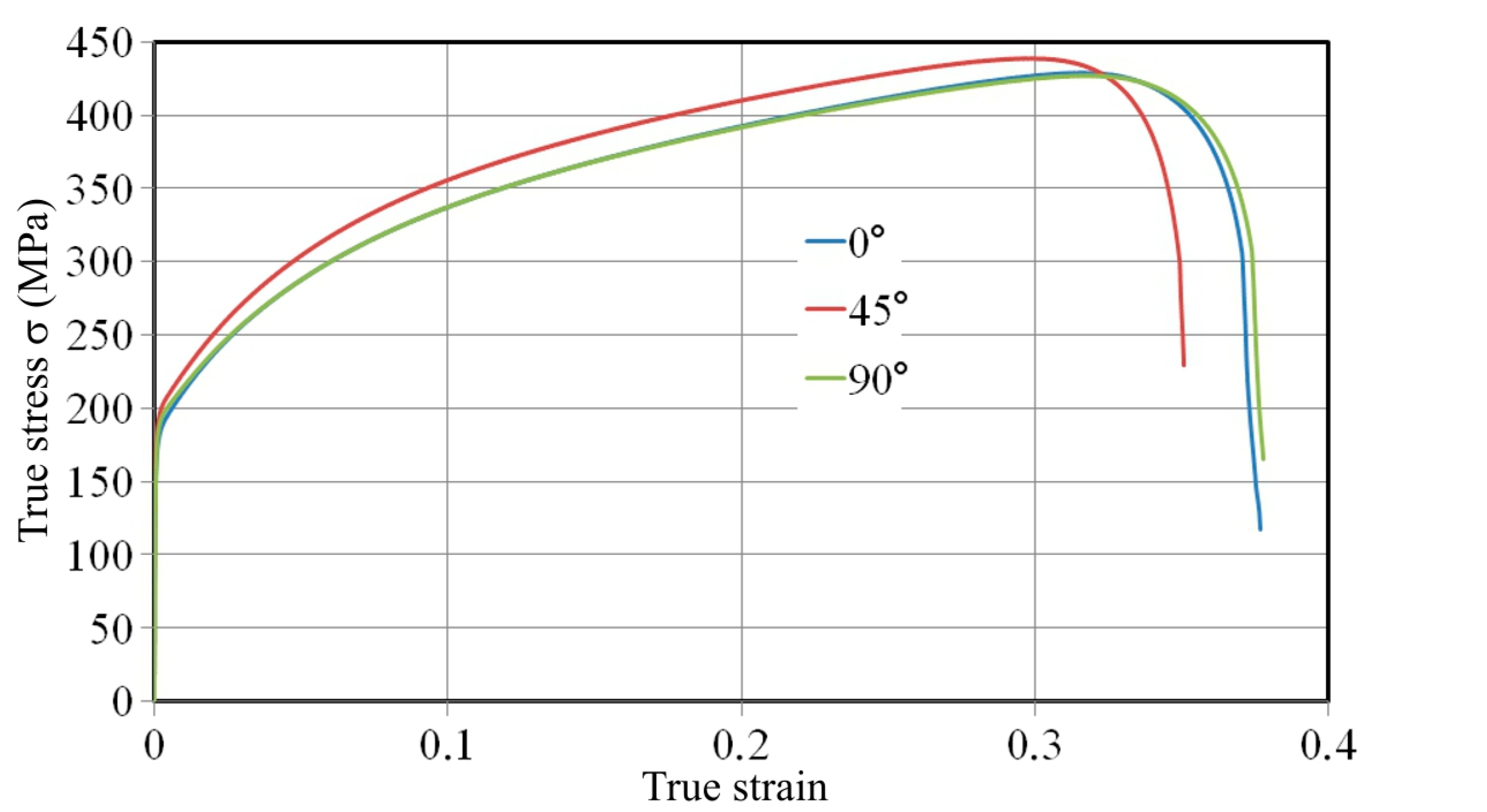
Figure 2.
The experimental setup: 1—punch; 2—die; 3—sample; 4—punch stroke controller; 5—guide columns; and 6—force transducer.
Figure 2.
The experimental setup: 1—punch; 2—die; 3—sample; 4—punch stroke controller; 5—guide columns; and 6—force transducer.

Figure 3.
The schematic for the measurement of springback.

Figure 4.
Boundary conditions in V-bending model of the sample cut along the sheet rolling direction.
Figure 4.
Boundary conditions in V-bending model of the sample cut along the sheet rolling direction.
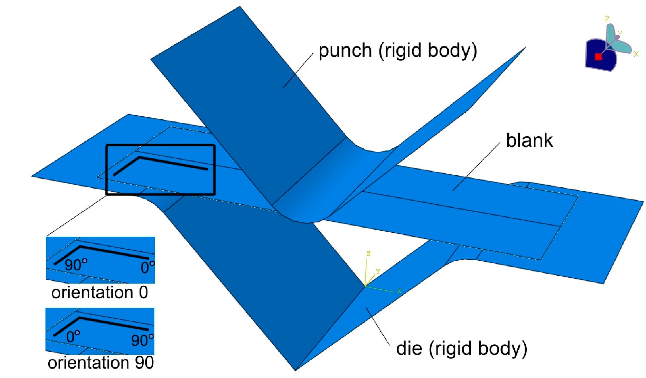
Figure 5.
Change of computational time with a number of integration points for Gauss’ quadrature and Simpson’s rule.
Figure 5.
Change of computational time with a number of integration points for Gauss’ quadrature and Simpson’s rule.
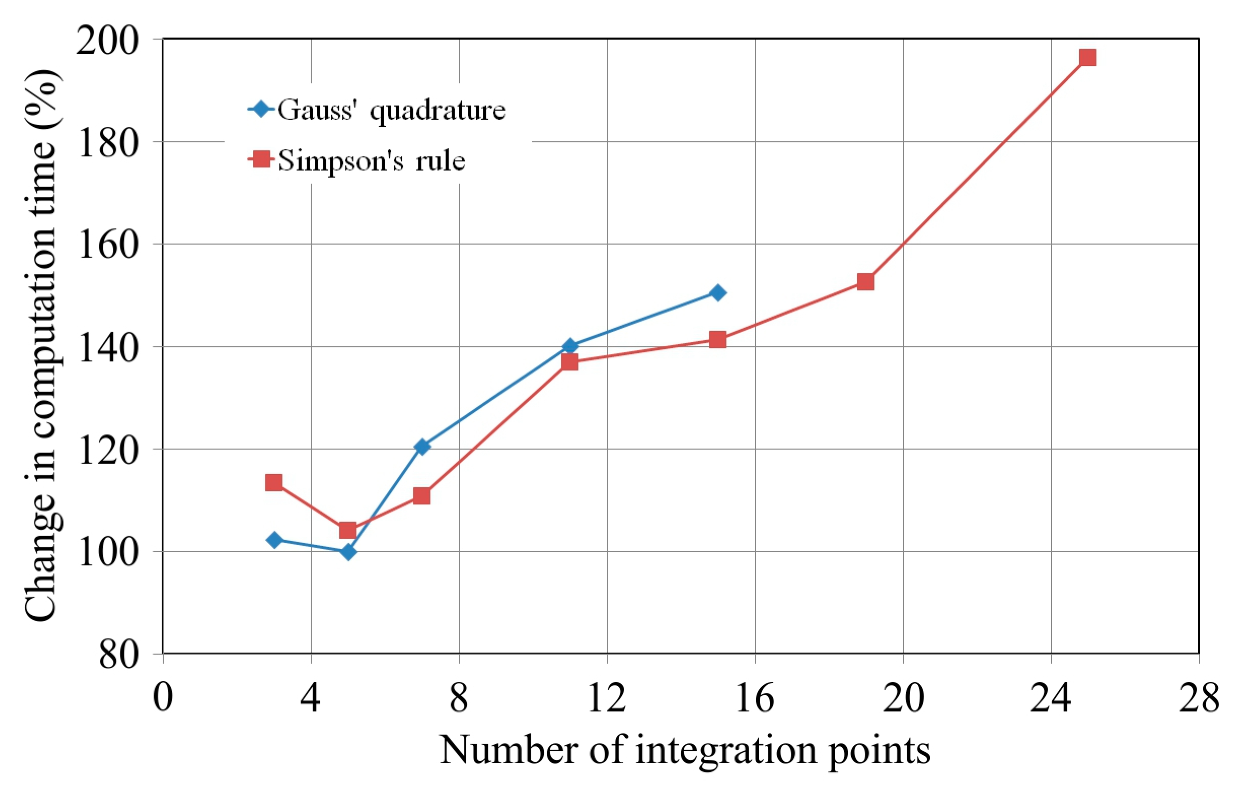
Figure 6.
Effect of a number of integration points on the value of the springback coefficient K for Gauss’ quadrature and Simpson’s rule.
Figure 6.
Effect of a number of integration points on the value of the springback coefficient K for Gauss’ quadrature and Simpson’s rule.

Figure 7.
Comparison of the springback coefficient value determined experimentally and by the FEM approach (Gauss’ quadrature, five integration points) for samples oriented according to (a) the rolling direction (0°) and (b) transverse to the rolling direction (90°).
Figure 7.
Comparison of the springback coefficient value determined experimentally and by the FEM approach (Gauss’ quadrature, five integration points) for samples oriented according to (a) the rolling direction (0°) and (b) transverse to the rolling direction (90°).
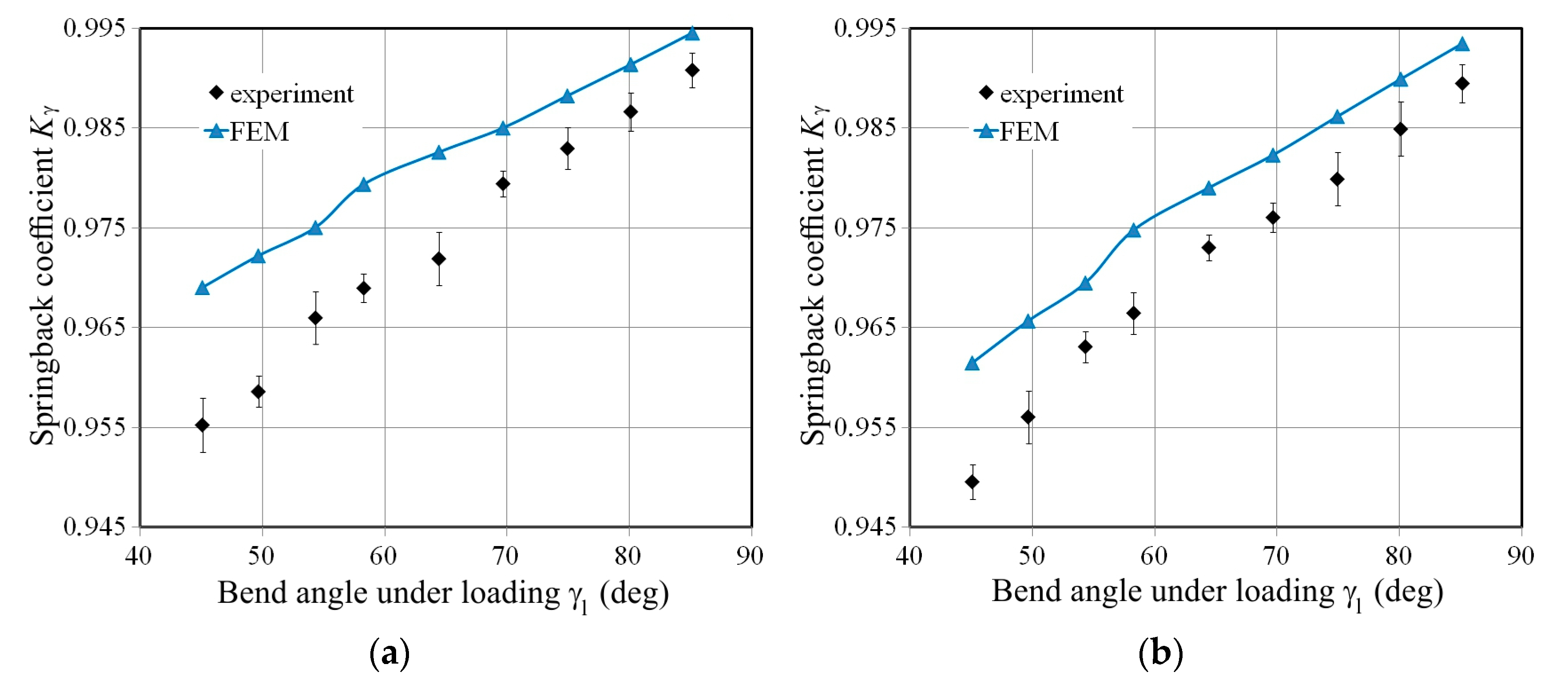
Figure 8.
The bending characteristics of material.

Figure 9.
Stress and strain state during V-bending of a sheet strip.

Figure 10.
Deviation of the sample profile in width direction.
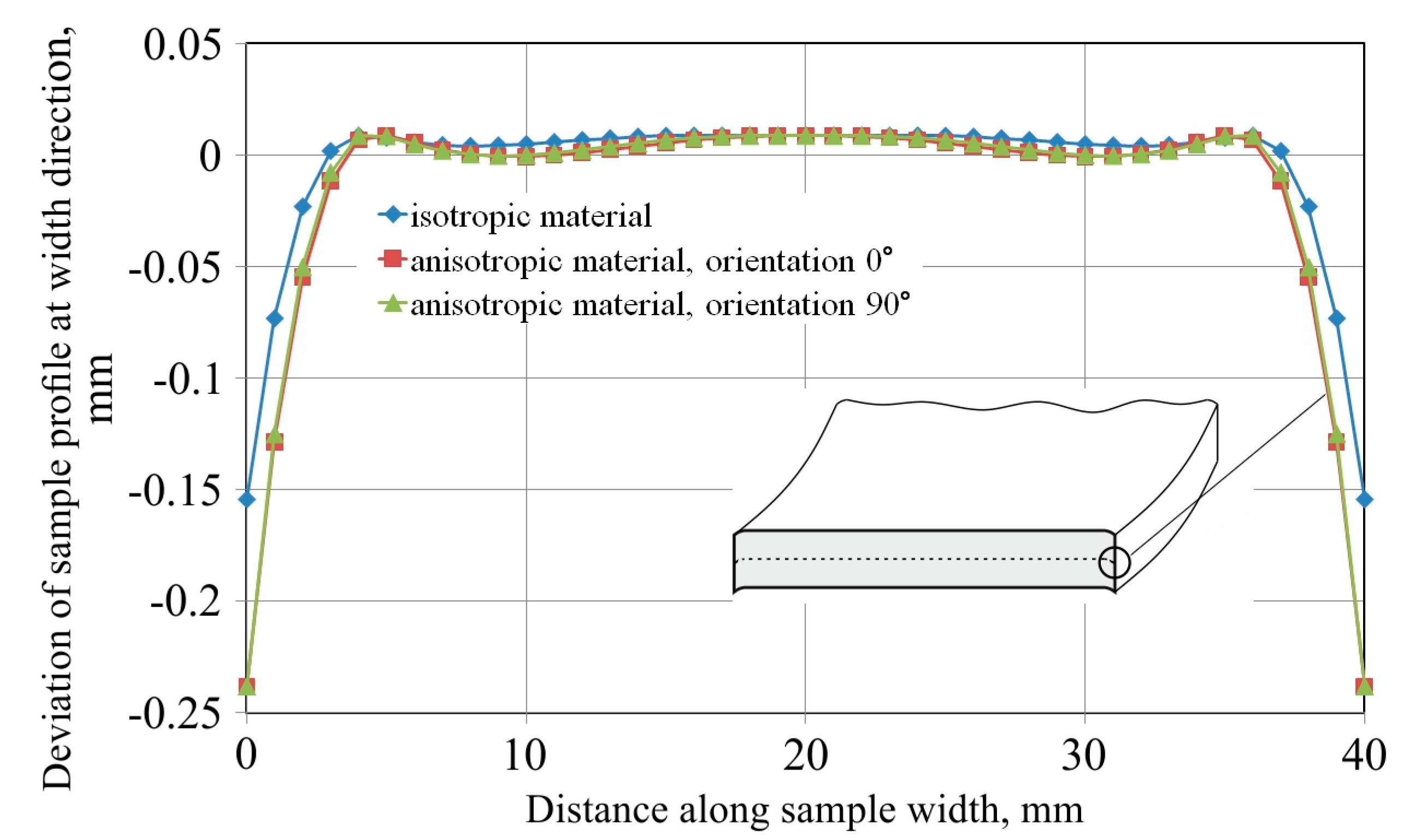
Figure 11.
The HMH stress distribution (left) under loading and (right) after unloading, for (a) samples with isotropic material and (b) anisotropic material oriented at 0° and (c) 90°, for a punch depth under loading of 18 mm.
Figure 11.
The HMH stress distribution (left) under loading and (right) after unloading, for (a) samples with isotropic material and (b) anisotropic material oriented at 0° and (c) 90°, for a punch depth under loading of 18 mm.
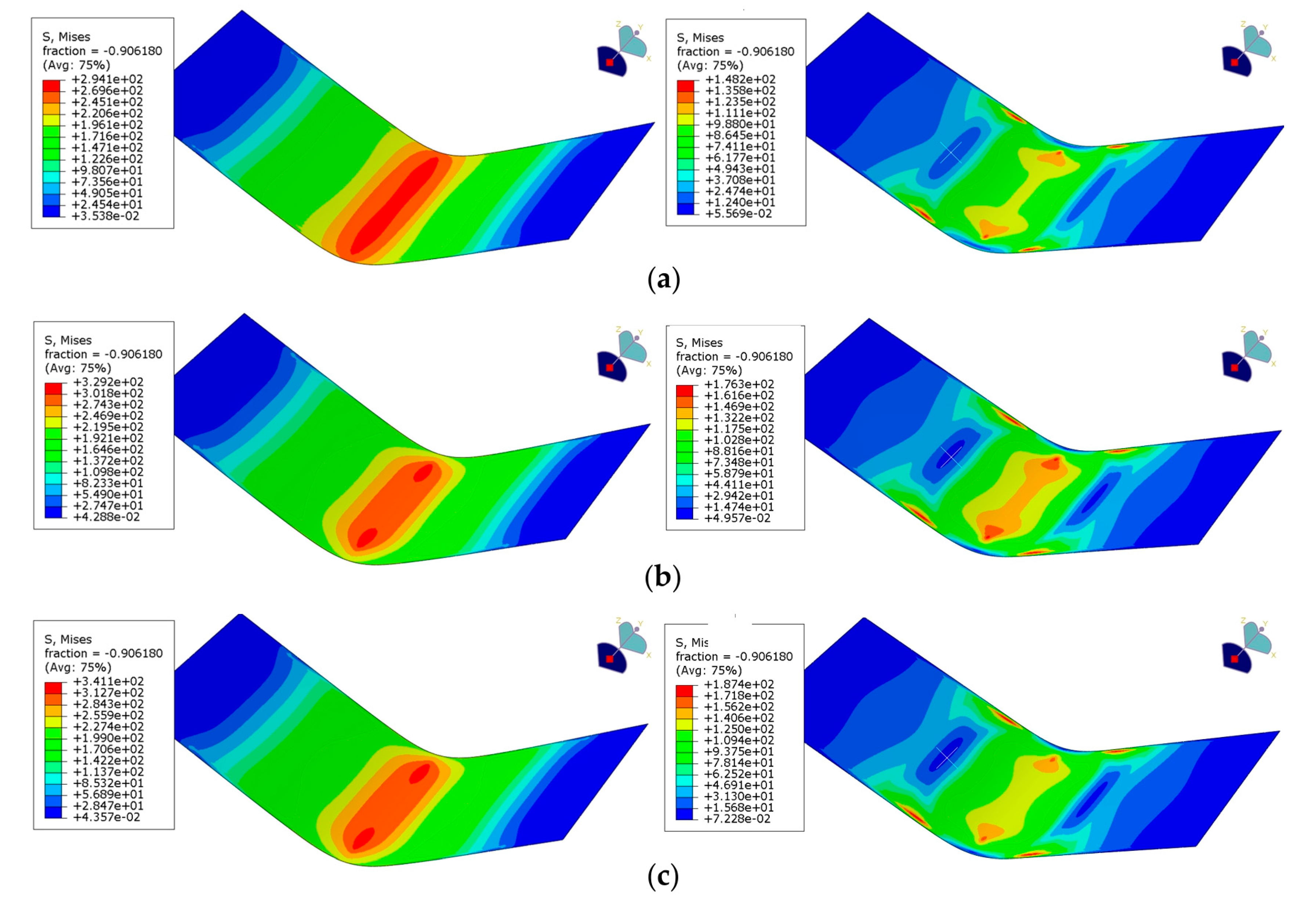
Figure 12.
Effect of bend angle under loading on the springback coefficient Kγ determined for sample orientation 0.
Figure 12.
Effect of bend angle under loading on the springback coefficient Kγ determined for sample orientation 0.
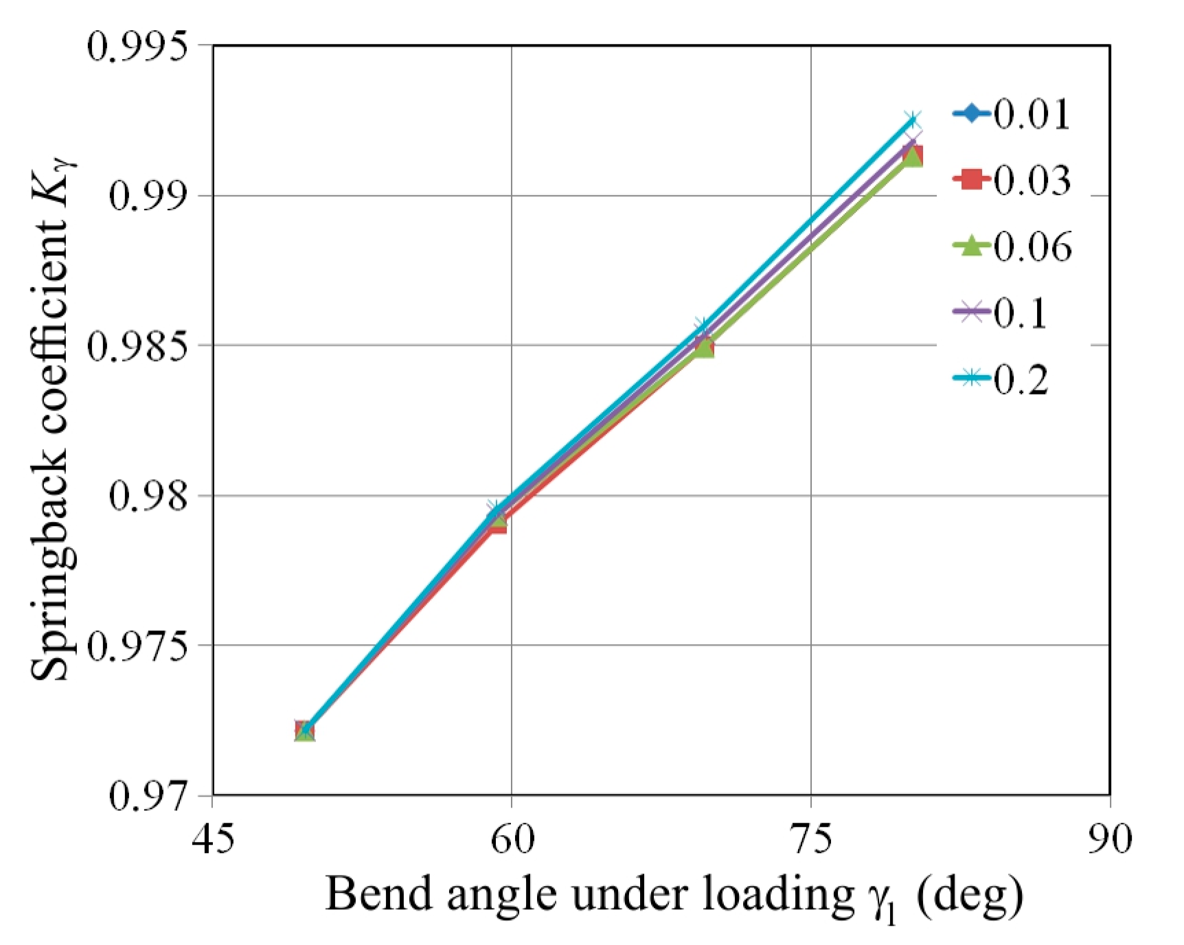
Figure 13.
Effect of the bend depth under loading fl on the punch contact angle γp.


Table 1.
Mechanical properties of the tested sheets.
| Orientation | Yield Stress σy (MPa) | Ultimate Tensile Strength σm (MPa) | Strain Hardening Coefficient C (MPa) | Strain Hardening Exponent n | Lankford’s Coefficient r |
|---|---|---|---|---|---|
| 0° | 182.1 | 322.5 | 549.3 | 0.214 | 1.751 |
| 45° | 196 | 336.2 | 564.9 | 0.205 | 1.124 |
| 90° | 190 | 320.9 | 555.2 | 0.209 | 1.846 |
| Average value | 191.02 | 328.9 | 558.57 | 0.208 | 1.461 |
© 2017 by the authors. Licensee MDPI, Basel, Switzerland. This article is an open access article distributed under the terms and conditions of the Creative Commons Attribution (CC BY) license (http://creativecommons.org/licenses/by/4.0/).
Share and Cite
MDPI and ACS Style
Trzepiecinski, T.; Lemu, H.G. Effect of Computational Parameters on Springback Prediction by Numerical Simulation. Metals 2017, 7, 380. https://doi.org/10.3390/met7090380
AMA Style
Trzepiecinski T, Lemu HG. Effect of Computational Parameters on Springback Prediction by Numerical Simulation. Metals. 2017; 7(9):380. https://doi.org/10.3390/met7090380
Chicago/Turabian StyleTrzepiecinski, Tomasz, and Hirpa G. Lemu. 2017. "Effect of Computational Parameters on Springback Prediction by Numerical Simulation" Metals 7, no. 9: 380. https://doi.org/10.3390/met7090380
Note that from the first issue of 2016, this journal uses article numbers instead of page numbers. See further details here.