Article

Synthesis of Pure NiTiSn by Mechanical Alloying: An Investigation of the Optimal Experimental Conditions Supported by First Principles Calculations

ICGM, CNRS, Université de Montpellier, ENSCM, 34095 Montpellier, France
*
Author to whom correspondence should be addressed.
Metals 2018, 8(10), 835; https://doi.org/10.3390/met8100835
Submission received: 14 September 2018 / Revised: 13 October 2018 / Accepted: 15 October 2018 / Published: 17 October 2018
(This article belongs to the Special Issue Heusler Compounds)

Abstract

:
Synthesis of NiTiSn by a mechanical alloying process followed by a high temperature thermal annealing was studied. Experiments were conducted varying parameters like the provided energy, the mechanical alloying reaction time, as well as the annealing temperature and duration. Based on the careful investigation of the phases present in the samples by systematic X-ray diffraction (after mechanical alloying and after annealing) and selected microscopy analyses, a reaction mechanism is proposed supported by theoretical calculations at the DFT (Density Functional Theory) level. An energy window to prepare directly NiTiSn has been evidenced. Highly pure NiTiSn has also been obtained by conversion from a multicomponent precursor obtained by low energy mechanical alloying.

Graphical Abstract

1. Introduction

As the worldwide energy demand continuously increases, finding new efficient materials to respond to always higher requirements, but also to improve properties of already known materials, remains challenging. Numerous and interesting researches have been reported up to now in the field of energy storage and conversion, aiming to limit the dependence on fossil fuels and the global warming effects. Thermoelectric (TE) materials, able to reversibly convert thermal energy into electricity, have acquired recently new popularity and renewed and increasing interest. The thermoelectric efficiency of a material depends on its ZT value expressed as α2T/ρκ where α is the Seebeck coefficient (or thermopower), ρ the electrical resistivity, κ the thermal conductivity, and T the absolute temperature. The higher the figure of merit (ZT) value, the better the performances of the TE module. Among TE materials, the class of Heusler compounds is remarkable for its multifunctional character [1], and therein, NiTiSn is probably the most widely studied half-Heusler compound. High abundance of its elements and potentialities for its use in intermediate (450–500 °C) temperature ranges make this compound attractive and have motivated scientists to understand its behavior and to interpret and improve its properties [2,3,4,5,6,7,8,9,10,11]. Available literature data, considered at the beginning of this study, was mainly dedicated to NiTiSn prepared by arc-melting and submitted to additional treatments. In a recent paper, a team of scientists has compiled the various treatments commonly used after the synthesis by arc-melting half-Heusler alloys [12]. High temperature annealing and mostly hot-pressing spark plasma sintering (SPS) consolidation, which not only densifies, but homogenizes the material and reduces the amount of side phases, have been used [13]. It is usually admitted that materials prepared in this way mainly contain NiTiSn, but also side phases as Ni2TiSn, Ti6Sn5, and Sn which are hard to eliminate even through annealing. The difficulty to obtain a single-phase NiTiSn material was well underlined in a recent paper reporting a significant spread of the results due to residual phases that affect the transport properties. It is clearly specified that little attention has been paid to the influence of minority phases on the TE performances, a major drawback in the design of improved and stable TE modules [14]. Influence on microstructure and TE properties of the initial preparation method and the pressing conditions, is also evidenced in a recent work reporting on the microwave synthesis of NiTiSn [13].
Alternate routes remain very scarce in the literature and some recent reports present thin films obtained by DC (direct current) magnetron sputtering [15] or materials prepared with a levitation furnace or microwave heating [13,16,17]. Interestingly, these latter samples are close in composition with the arc-melted samples, which is rather consistent since they are both obtained by solidification of a melt. The presence of Ni3Sn4 has been found in a few percent in the consolidated materials [8]. An earlier work focused on mechanical alloying (MA) followed by SPS densification, stated that NiTiSn cannot be obtained by MA, even after long reaction times [5].
Mechanical alloying is a simple method whose usage started to increase considerably several decades ago to synthesize a broad range of materials [18]. Its greatest advantage is the ability to mix reactive components at the nanoscale and to induce chemical reactions in powder mixtures at room temperature (or at temperatures much lower than normally required). Since kinetics predominate over thermodynamic constrains, the limitations imposed by the phase diagram do not hold for such a solid-state processing technique. This renders accessible non-equilibrium or even equilibrium compounds that are difficult or impossible to obtain by conventional melting techniques [19]. Nevertheless, MA is a complex process that involves many parameters as the type of mill, milling containers and balls, milling atmosphere, milling speed and time, etc., that are not always independent. During MA, energy is transferred to particles due to frequent collisions that cause plastic deformation, breakage and particle size reduction increasing the reactive surface, enabling the existence of composite materials and enhancing diffusion. The energy provided to the sample depends on various parameters such as the rotation speed, the hardness of the grinding bowls, the nature and number of balls, the ball-to-powder ratio, etc. All the parameters being preserved, the energy directly depends on the rotation speed. Even if a direct relation is not easy to formulate, rotation speed and energy are highly correlated and vary in the same direction. Trials to model this complex relation remain scarce and limited to a single ball problem [20,21]. A recent work describes a stochastic model to investigate the kinetics of gradual mechanical reactions in simple conditions (shaker mill and single-ball), which is suitable to obtain helpful and valuable microscopic parameters [22].
Resulting materials are most of the time metastable and expected to transform in thermodynamically stable products. Then subsequent annealing may be needed to achieve the alloying process [23]. It should be stressed that in some cases the material is hold in a metastable state (otherwise named activated material) prior to further reaction [24]. Detailed information on this method is available in comprehensive reviews in which the role of the various parameters is well discussed and where many examples are provided [25,26,27]. It is also interesting to report the numerous uses of MA for the manufacture of advanced engineering materials [26], for example, steels with high boron content for nuclear technology materials [28].
The present work reports the preparation of NiTiSn by mechanical alloying followed by high temperature thermal annealing. Parameters like energy and reaction time as well as annealing temperature and duration have been varied in this study. A reaction mechanism is proposed, based on the analysis of experimental results, and supported by theoretical calculations.

2. Experimental Techniques and Calculation Methods

Commercial powders (~150 microns) have been used in stoichiometric proportion for this study: Ni (Sigma-Aldrich, 99.99%), Ti (Acros-Organics, 99.7%), and Sn (Alfa-Aesar, 99.85%). To remain critical on this work, powders used in this study have a relatively high, but not the highest purity level. It should be checked in future works that this weak impurity level does not modify the behavior of the main elements during the reaction and does not have important consequences on the results.

2.1. Classical Routes (Arc Melting, Diffusion…)

NiTiSn has been prepared by arc-melting [29] in a home-made apparatus (the stainless steel chamber is connected to secondary vacuum and argon supply systems, the copper holders of the tungsten electrode and of the sample are water-cooled). The fused ingot was submitted to two additional fusion steps for homogenization.
Trial to obtain NiTiSn by “solid state” diffusion at 850 °C, better described as a solid-liquid reacting method since Sn is liquid at this temperature, was realized by thermal treatment for 30 days of a pellet placed in an evacuated (10−2 mbar) and sealed silica tube.
Self-propagating high-temperature synthesis (SHS) [30] was conducted (Ar atmosphere, 8 bars) by varying the tension applied to a tungsten wire placed very close to the sample; the produced heat is transferred to the sample and initiates the exothermic reaction of elements.

2.2. Mechanical Alloying (MA)

Experiments were performed with a total powder amount of 2 g placed together with 18 silicon nitride (Si3N4) balls of 10 mm in diameter into an airtight silicon nitride bowl of 80 mL. The grinding bowls equipped with the SelfLOCK technology and silicon seal ring were filled with pure argon and tightly closed avoiding any leak. The ball-to-powder ratio of 14:8 was kept constant (see in Reference [25,26,27] for details on this parameter) in all the experiments conducted using a high-performance Fritsch GmbH planetary Micro Mill Pulverisette 7 premium line. MA takes place through high-energy impacts (and friction) mainly between the grinding balls, but also between the balls and the walls of the bowl. For that, the grinding bowl rotates around its own axis on a main disk rotating in the opposite direction (transmission ratio 1:−2). The rotation speed of the main disk was taken from 300 to 800 rpm, thus rotation speed of the grinding bowls went from 600 to 1600 rpm. The bowl temperature, evaluated in preliminary experiments after 30 min of rotation, was found to remain almost constant even at the highest speeds (energies). Consequently, experiments were carried out using sequences of 30 min rotation followed by 10 min standby to prevent any heating of the bowls. The actual reaction time was varied from 1.5 to 43 h. In our experiments, all the parameters being fixed, except the rotation speed, the provided energy depends only on the rotation speed. These two quantities vary in the same way but it is difficult to find a clear relationship between them even if a cubic dependence of the energy on the speed has been proposed in Reference [31]. Nevertheless it is worth mentioning that this model remains limited to the dynamics of a single ball in a vial.

2.3. X-ray Diffraction

All the samples prepared in this work were analyzed by powder X-ray diffraction (XRD) shortly after synthesis. Powders (calibrated at 20–30 μm) were analyzed using the Bragg–Brentano technique within, at least, the 2θ angular range 20–70°. It is worth mentioning that no visible change in the pattern was noted after aging the final material (checked for a few samples) at an ambient atmosphere up to several months. Powders were subsequently pressed into pellets (13 mm in diameter, 10 tons) and inserted into silica tubes sealed under vacuum for annealing. Three temperatures, 750, 850, and 950 °C, have been regularly used for thermal treatments during 5–15 days in a tubular furnace (temperature was measured near the sample). After annealing, the product was ground in an agate mortar before its XRD pattern was recorded again. An analytical X’Pert diffractometer (Philips, Panalytical, France), equipped with a hybrid monochromator (parabolic multilayer mirror and two-crystal monochromator, Cu-Kα radiation) and the Xcelerator detector (Philips, Panalytical, France), was used. Profile refinements and Rietveld analyses were performed using program Jana 2006 [32].

2.4. Electron Microscopy

Energy-dispersive X-ray spectroscopy (EDX) and scanning electron microscopy (SEM) were performed using an Oxford Instrument Environmental Scanning Electron Microscope, equipped with an X-Max large area SDD sensor that allows excellent sensitivity, precision, and resolution. Powdered samples were pressed into pellets and polished prior to analysis. Typically, two specimens and at least three chemical analyses focused on each component were performed.

2.5. Calculation Methods

Our studies have been performed at the Density Functional Theory (DFT) level, which is a computational quantum mechanical modeling method used in materials science to investigate the electronic structure (principally the ground state) of many-body systems, in particular the condensed phases. Using this theory, the properties of a many-electron system can be determined by using functionals, which in this case is the spatially dependent electron density [33]. Calculations were carried out simultaneously with the codes CASTEP (CAmbridge Sequential Total Energy Package) and VASP (Vienna Ab-initio Simulation Package) within the Generalized Gradient Approximation (GGA) and the Perdew-Burke-Ernzerhof (PBE) parameterization was applied [34,35]. The first Brillouin zone was integrated using Monkhorst-Pack k-point meshes [36].
For each compound, starting from the experimental structure data (Table 1), the geometry was optimized by relaxing both the lattice parameters and the atomic positions. The converged total energies have been used to calculate the formation enthalpy of the different compounds.
CASTEP uses plane-wave basis sets to treat the valence electrons and pseudo potentials to approximate the potential field of ion cores [55,56]. For each element, USPP (Ultra-Soft Pseudo Potentials) were taken as generated according to the Vanderbilt scheme [57]. The electronic states 3d84s2 for Ni, 3d24s2 for Ti and 5s25p2 for Sn are treated as valence states in the chosen pseudopotentials. The k-point separation was set to 0.04 Å−1 in each of the lattice directions. Kinetic cutoff energies for the plane wave expansion of the wave functions were set at 550 eV. Geometry optimizations were carried out at ultrafine quality using the BFGS (Broydon-Fletcher-Goldfarb-Shanno) algorithm. Tolerances were 5 × 10⁻⁶ eV/atom for energy, 0.01 eV/Å for forces and 5 × 10⁻⁴ Å for maximal atom displacements.
Alternately, VASP [55,56] uses the PAW (projector augmented waves) technique [58,59]. Standard versions, Ni, Ti_sv, and Sn_pv, of the PAW potentials have been used. Ten electronic states are included in the valence shell for Ni (3d84s2), twelve for Ti (3s23p63d24s2) and four for Sn (5s25p2). The “accurate” precision setting was used to avoid wrap-around errors (energy convergence for the cell: 10−5 eV; force convergence: 10−4 eV/Å). The reciprocal space mesh was set so as to obtain a number of k-points multiplied by the number of atoms higher than 500. The cutoff energy was systematically set to 450 eV. For the Ni-containing phases, the GGA+U method of Dudarev et al. has been also used [60]. The need to use a GGA+U description for the Ni-containing phases, described in Reference [61], is motivated by a better description of the experimental ternary phase diagram compared to the standard GGA description. The parameter Ueff for the Ni atoms was set to 3.5 eV as detailed in Reference [61].

3. Results and Discussion

In our work, NiTiSn was primarily prepared by mechanical alloying but for comparison, samples were also prepared by classical fusion methods (arc-melting, induction furnace, or self-propagating) and by solid-liquid reaction from the elements. It is useful to recall here that, in agreement with the phase diagram, direct preparation of NiTiSn from the melt is impossible because the first phase to crystallize is the full Heusler Ni2TiSn compound [62]. A neutron diffraction study even concludes that arc-melted NiTiSn naturally incorporates a ~6% Ni-excess leading to a very weak increase of the lattice parameter [63]. Furthermore, in agreement with the sudden decrease by ~20% of the total energy per atom (shown by our DFT calculations) when the composition comes close to NiTiSn, the transformation from Ni2TiSn (Fm 3 ¯ m) to ordered NiTiSn (F 4 ¯ 3m) does not proceed through a continuous process as a consequence of the symmetry change [9].

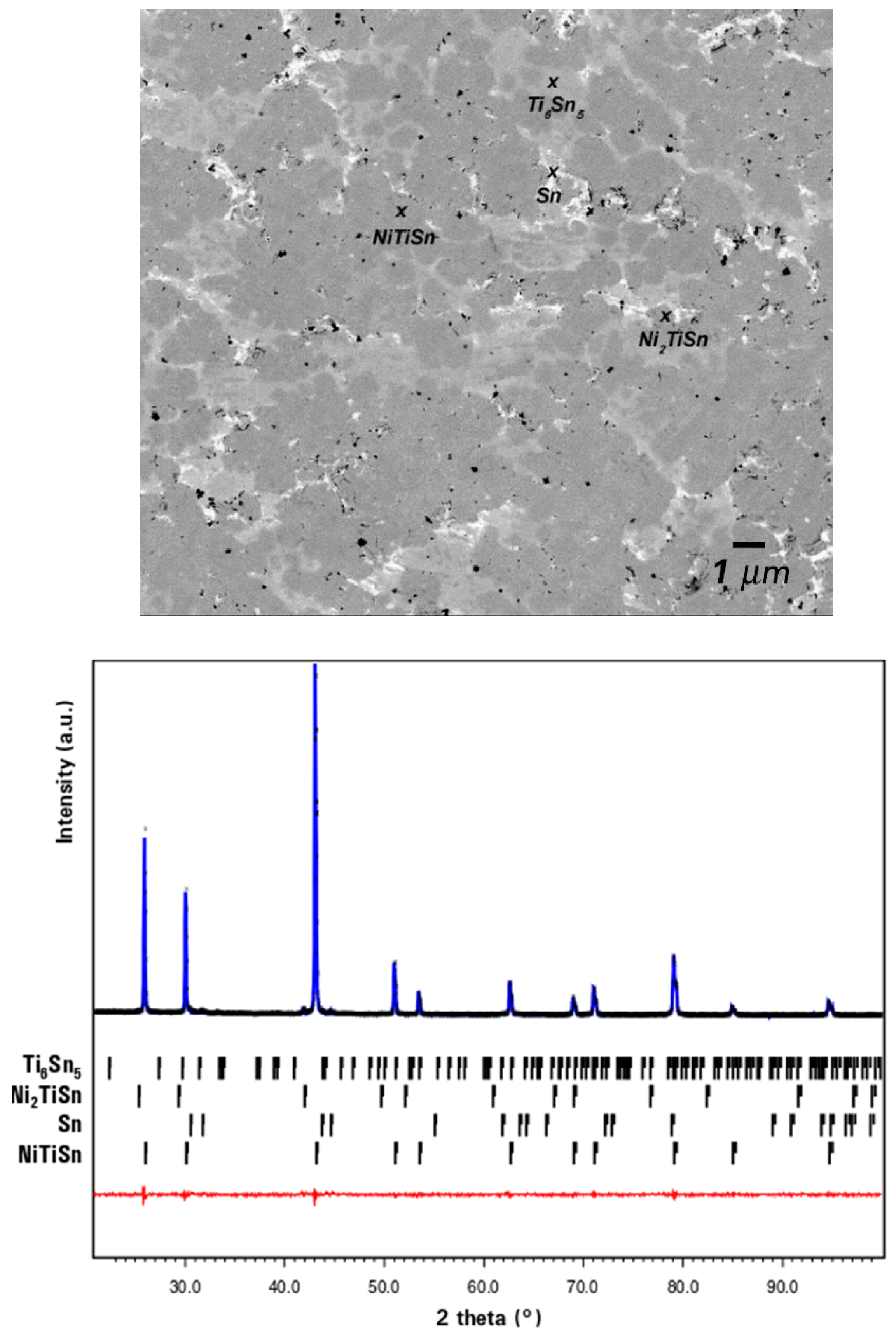
3.1. Preparation by Classical Fusion Methods

Analyses of the arc-melted material prepared in this work confirm the presence of NiTiSn and of the secondary phases Ni2TiSn, Ti6Sn5, and Sn, easily visible as grey and white domains in typical SEM images (Figure 1), while black regions account for the porosity of the sample before annealing.
The Rietveld fit of the XRD pattern leads to an approximate ratio NiTiSn:Ni2TiSn:Ti6Sn5:Sn of 62:24:10:4. After annealing for 10 days either at 750 or 850 °C, these minority phases remain in lower quantities with proportions converging to 97.2:1.6:0.2:1.0. Interestingly, trials to synthesize NiTiSn by self-propagating high-temperature (SHS) or induction furnace led to similar results with a final material displaying equivalent or even poorer quality.
As commonly reported [13,14,62], NiTiSn is always supplemented by small quantities of secondary phases when obtained by fusion. In such a method, and especially in arc-melting, the sample necessarily passes by the liquid state (all the elements are liquid above 1670 °C). According to the calculated and experimental ternary diagrams [64,65], cooling this liquid mixture leads to the formation of solid NiTiSn but also Ni2TiSn, Ti6Sn5 and Sn. On this matter, a certain emphasis has to be put on the peritectic decomposition of NiTiSn at 1182 °C and the congruent melting of Ni2TiSn at about 1450 °C. Subsequent thermal treatments, even long-time annealing, fail in homogenizing the material, complete elimination of metallic tin being most likely limited by its poor diffusion ability. NiTiSn prepared by fusion methods is characterized by a good crystallinity, and after the necessary suitable thermal treatments, by a rather good purity, but always containing a more or less great quantity of impurities that may affect its properties.

3.2. Preparation by Solid–Liquid Reacting Methods

A pellet made of a stoichiometric NiTiSn mixture homogenized by ball milling at low energy, was sealed under vacuum in a silica tube, heated to 850 °C and maintained at this temperature for 30 days to realize the “solid state” synthesis of NiTiSn. Actually, the reaction does not truly take place in the solid state, but between liquid tin and solid Ni and Ti components. This clearly shows that the reaction may occur at a temperature remaining far below the Ni and Ti melting temperatures of 1455 and 1668 °C and is rather limited by diffusion processes. Even if NiTiSn was the major component in the sample (a little less than 80 wt % according to the XRD pattern refinement), amounts of secondary phases (confirmed by EDX) remain very important, with ~6% of Ni2TiSn and ~15% of unreacted tin (Figure S1, Supplementary Material). This synthesis route is comparable with the reactive sintering at 1000 °C [9] between Sn and a NiTi powder (previously obtained by arc-melting) followed by an additional hot pressing treatment to prepare NiTiSn, still containing Ni2TiSn nano-domains.

3.3. Preparation by Mechanical Alloying (MA)

The alternative path through MA deserves greater attention. Since it involves processes in which kinetics predominate, the nature of the intermetallic phases in the material should be different from that resulting from the solidification of a melt by classical fusion methods [19]. This also applies to the secondary phases likely to form during the synthesis.
In order to better understand the reactions that occur in the MA processes, a series of samples have been prepared in this work. Apart from the reaction time and the rotation speed, experimental conditions such as chemical composition (1:1:1 stoichiometry), total weight of reactants, grinding balls, ball-to-powder ratio, and argon atmosphere were kept strictly identical for all the experiments.
As MA can provide contamination, we checked by an attentive examination of the SEM images and by EDX chemical analysis that no Si trace coming from the Si3N4 coating was present in the samples. On the other hand, it is likely that titanium grains used for our experiments are covered with a very thin oxide film, although the powders were submitted to primary vacuum (desorption) before handling under argon atmosphere prior to MA experiments. Yet, no titanium oxide was detected in our MA samples by careful examination of the SEM images contrarily to what was observed in the aforementioned experiments [5]. It can reasonably be assumed that the special locking system enables a very effective and hermetic closing of the Si3N4 bowls, thus avoiding any further oxidation of titanium. Even if EDX is not a fully suitable method to precisely quantify the content of light elements, the relative oxygen proportion in MA samples remains within classical limits, as low as in arc-melted samples. Moreover, no contaminated domains can be detected by contrast differences in the SEM images. SEM/EDX microscopy techniques were additionally used to characterize our samples, since small fractions of a phase cannot not be resolved with XRD analyses. Products were systematically analyzed using powder XRD shortly after MA reaction and later after annealing. Their composition at the end of milling was found strongly dependent on the experimental conditions, which is not too surprising since materials can reach different alloying degrees depending on the reaction time. This has been useful to interpret the phase formation along the MA process and the obtention of the “fully alloyed” state after annealing.

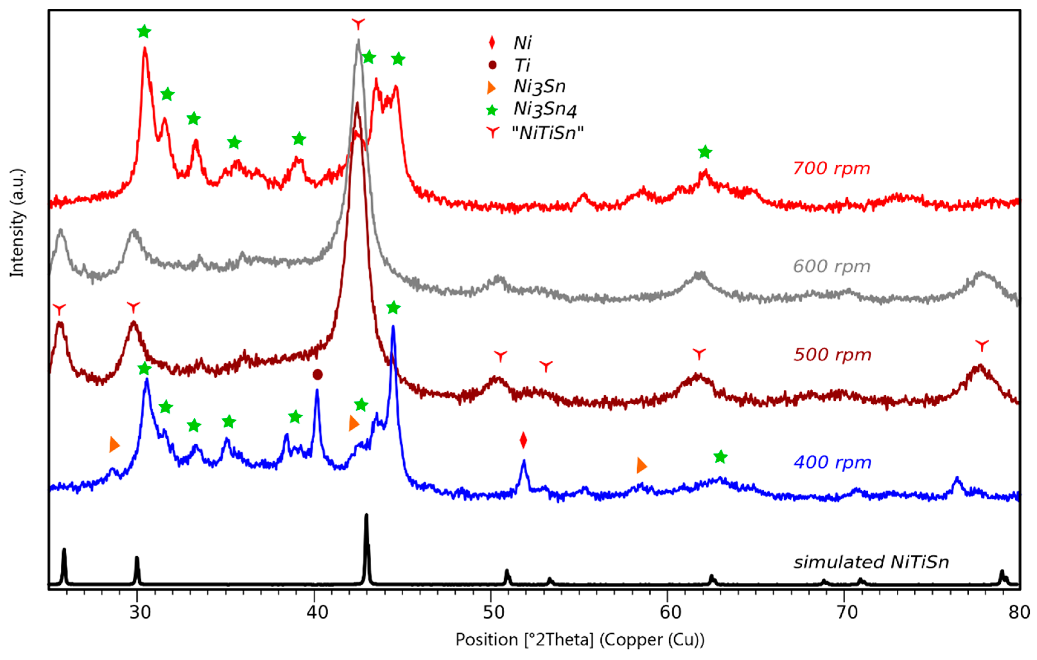
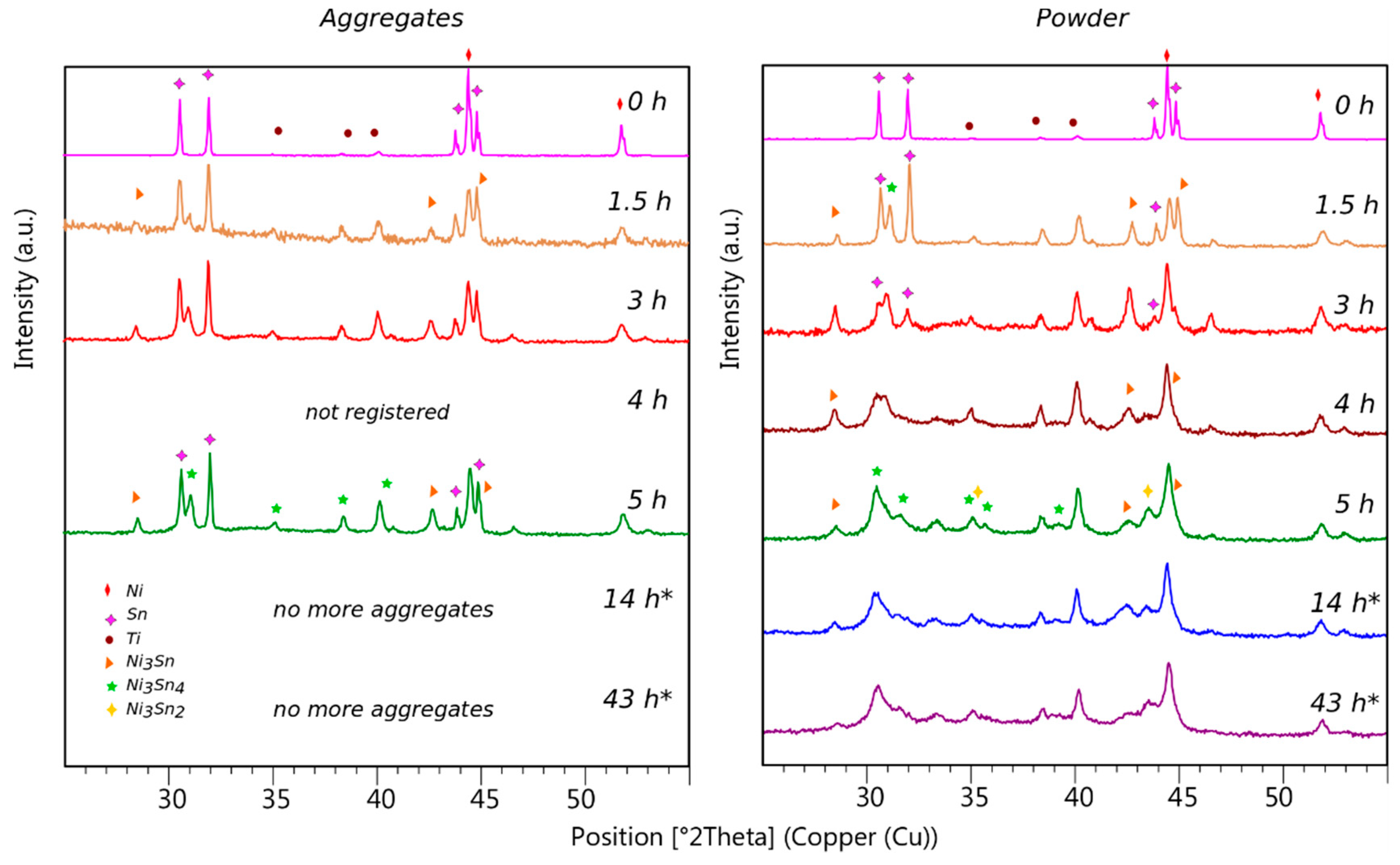
3.3.1. Influence of the Provided Energy

To investigate the influence of the provided energy on the compounds formation, MA experiments were performed at various rotation speeds in the range 300–800 rpm. Preliminary tests indicated that no significant reaction occurs below 300 rpm and rotation speeds above 800 rpm were avoided to protect the bowls and balls from damage.
The XRD patterns of samples milled for 5 h are represented in Figure 2, comparatively, with the pattern recorded for a stoichiometric mixture of elemental powders that would correspond to a treatment at null rotational speed. Note the weakness of the Ti diffraction lines compared to the ones of Ni and Sn, probably due to a poorer crystallinity. At first glance, a difference clearly appears between samples obtained at the highest and lowest energies. The transformation is easily noticeable in the low 2θ angular domain with the apparition of a diffraction peak centered at nearly 26° and assigned to the NiTiSn (111) plane.
At low rotation speeds, typically below 500 rpm, patterns display relatively sharp diffraction lines and no characteristic peak of NiTiSn is observed. These patterns are characteristic of a multicomponent material in which we identified the phase Ni3Sn4 and in smaller quantities Ni3Sn and Ni2Sn3. Note that the full indexation of the pattern is not possible since the main diffraction lines of several compounds may occur in the same angular domain. Moreover the mechanically alloyed powders are highly divided and poorly crystallized leading to weak and large peaks.
For samples obtained with the highest rotation speeds, the patterns display large peaks centered onto the angular positions expected for cubic NiTiSn. Line broadening is characteristic of a highly disordered and divided powder as is the case for this mechanically alloyed intermetallic compound. The lattice parameter refined by profile fitting of the patterns converges to ~6.00 Å, a value which is rather close to the lattice parameter of NiTiSn, generally given at 5.93 Å [38]. Nevertheless, it is not possible to unambiguously identify NiTiSn in the final product on the basis of only XRD, because peak broadening could mask the presence of other phases such as cubic Ni2TiSn (a = 6.10 Å). Actually, the two compounds display structural similarities and very close lattice parameters so that Ni2TiSn diffraction lines would appear close to those of NiTiSn (Table S1, Supplementary Material).
Subsequent EDX analyses have later proven these samples to be mainly formed of NiTiSn (Figure S2, Supplementary Material) and no occurrence of Ni2TiSn was detected. Diffraction patterns recorded for samples alloyed for 14 h (Figure S3, Supplementary Material) are comparable to those shown in Figure 2, and NiTiSn was not obtained for speeds lower than 500 rpm.
On the contrary, samples reacted for 43 h at 400–700 rpm are of greater interest because of the changes in their XRD patterns (Figure 3) when alloying is operated at the highest energies. The important feature is that, when the rotation speed is increased up to 700 rpm and beyond, NiTiSn is no longer the major component of the final material, which also contains large amounts of binary compounds, like for example, Ni3Sn4, but also elemental Sn.
Thus, it can be stressed that the total energy provided to the sample during the reaction is the driving force that determines which phases will form. The main result is the existence of a threshold at 500 rpm in the rotation speed, which must be crossed to form NiTiSn.
It can be asserted that, below this speed limit, the minimal impact energy needed to initiate a chemical change into the ternary alloy is not reached [22] and that the energy which is provided to the sample only leads to the formation of binary compounds. On the other hand, a too high energy is not favorable to form NiTiSn during the longest reactions. This leads to the fact that an optimal energy window exists for the direct formation of NiTiSn by mechanical alloying.

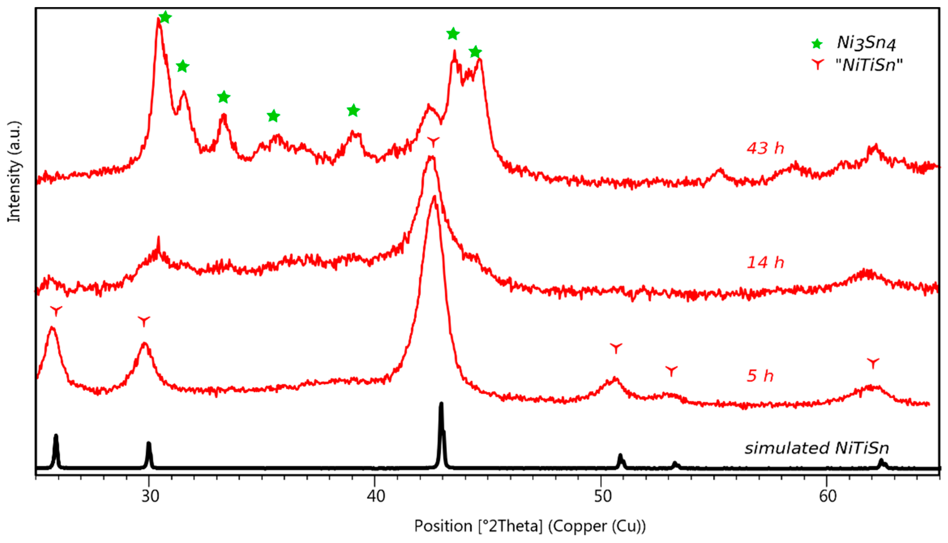
3.3.2. Influence of the Reaction Time

To investigate changes in the final material with reaction length, we have selected samples alloyed with the same energy but for increasing durations. Our choice is to discuss here the results obtained for samples reacted at 700 rpm (rather than 500 rpm) during 5, 14, and 43 h (Figure 4) because the higher intensity of the phenomena better illustrates our findings.
Keeping in mind that NiTiSn only forms at the beginning of the reaction as the almost unique component when the rotation speed is greater than 500 rpm, it is obvious that the pattern after 5 h of alloying is that of NiTiSn. Continuing the reaction up to 14 h does not considerably modify the nature of the final material, as shown by the diffraction lines at the same positions. Nevertheless, the diffracted intensity is lowered, the signal-to-noise ratio degraded and small bumps emerge in the 30–40° domain, which are signs of a loss of quality of the material. A longer reaction up to 43 h leads to the disappearance of NiTiSn, with no more characteristic peak in the 20–30° 2θ range, for the benefit of a compound that could be identified as Ni3Sn4 from pattern treatments. Moreover, the presence of peaks at the characteristic angular positions of Sn proves that some metallic tin has been released in the material.
Analogously, a considerably slower degradation phenomenon was observed for products prepared with a lower energy at 500 rpm (Figure S4, Supplementary Material). Small diffraction peaks associated to degradation phases and metallic tin are visible, even if in this case NiTiSn still remains the main component after 43 h of reaction. Below 500 rpm, NiTiSn does not form during the reaction and a multiphasic material mostly composed of binary Ni-Sn compounds is obtained. This is in agreement with a minimal impact energy needed to initiate the chemical changes evidenced in kinetic measurements [22] also showing that the number of collisions can be used, instead of the reaction time, as a kinetic parameter. An increase of the reaction time has no visible impact on the nature of the formed phases, and in no case, NiTiSn was observed even after long reactions extended up to 43 h.
Duration of the MA reaction affects the quality and the nature of the material. Binary Ni-Sn phases seem to be the easiest to form in MA processes with low energy contributions. Above the energy threshold corresponding to 500 rpm, it is NiTiSn that forms in the first stages and then gradually disappears when the reaction is continued (it is worth noting that the higher the energy, the faster this disappearance).

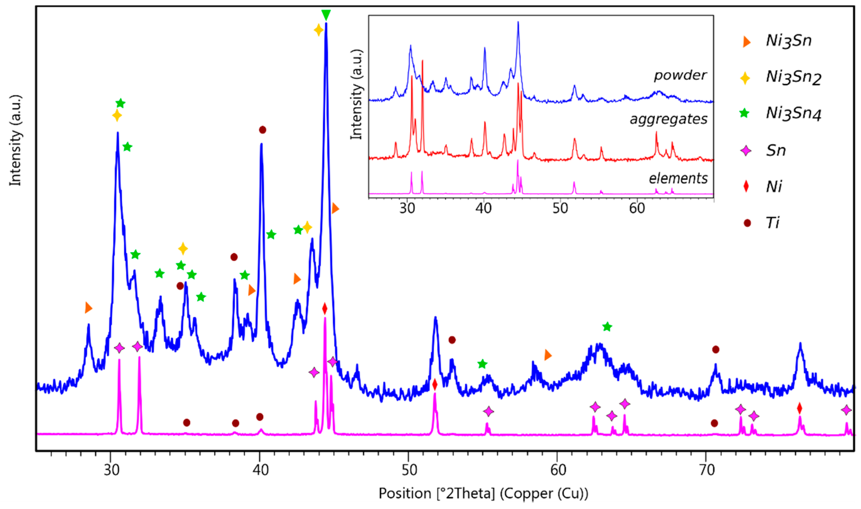
3.3.3. The Special Case of MA Experiments at 400 rpm

The results of experiments carried out at 400 rpm, which were briefly mentioned above, deserve an additional discussion. Quite similar materials were obtained whatever the milling time. Nevertheless, products from long experiments are only obtained as powders while those from short experiments (5 h) also contain aggregates with curious shapes (Figure S5). Initially, these aggregates were ground with the rest of the product for further analyses and because of their relative hardness, it can be stated that they are not made of pure tin.
From there, new experiments were carried out to check the reproducibility of this phenomenon and in each case, aggregates were found in the final product. Patterns collected respectively from the powder part and the aggregate part are very informative. They all display similar profiles and contain the diffraction lines of Ni-Sn binary phases formed in the MA reaction. However, in the patterns of the aggregates, intense lines at Sn positions reflect the presence of free tin in high content, which causes an overall pattern flattening. An in-depth analysis allowed the identification in the recovered products of three Ni-Sn binary phases in addition to rather large amounts of unreacted elements (Figure 5).
Thereafter, extra experiments were conducted at 400 rpm for shorter durations of 1.5, 3, and 4 h to understand the phenomenon and to propose a mechanism for the alloying reaction. Aggregates were always found in the final products and treated separately from the powder. After 1.5 h of reaction, the analogy between the patterns of the aggregates and the powder (Figure 6) is remarkable, clearly showing that Ni3Sn is formed in the first stages of the reaction, as indicated by the presence of its characteristic diffraction line at about 29°. After alloying for 3 h, products still contain Ni3Sn, but the difference between the aggregates (in which remains a high-content of Sn) and the powder (which contains both Ni3Sn2 and Ni3Sn4) is more important. Up to 5 h of alloying, rather similar features are observable. On the contrary, longer reactions of 14 and 43 h led to the disappearance of the aggregates, therefore the whole product was recovered as a powder whose pattern is comparable to that of a powder alloyed for 5 h.
According to the results of the short experiments, the main information is that Ni3Sn is detected in the reactionary medium as soon as the reaction starts, and then the phases Ni3Sn2 and Ni3Sn4 appear. The particular feature is that these phases, which are formed in the powder state at the beginning of the reaction, agglomerate themselves, sticking around the very malleable tin grains which could locally reach 232 °C (the melting temperature of Sn) due to the impacts with the grinding balls. Tin grains are then trapped inside the aggregates, acting as binding agents in such structures. The long reactions are likely to provoke the fracture and the division of these large aggregates in smaller grains, better suited to react, and to allow the reaction to continue. Finally, the product is typically characterized as a multicomponent material mainly composed of binary Ni-Sn phases, but which always contains substantial amounts of elemental powders.

3.3.4. Comment on Previous Results

To finish this section, let us tackle the MA experiments carried out by Zou et al. [5,66] only differing from our work by the SPS post-processing step (not done in our work). They concluded that direct synthesis of NiTiSn is not possible even for long milling times due to the easy formation of Ni3Sn4. Nevertheless, they stated that starting with a consequent Ti-excess (NiTi1.4Sn) and a subsequent SPS step (800/850 °C), they had obtained NiTiSn (90% pure) displaying n-type semiconducting behavior.
First of all, it is important to note that the comparison with previous works is fairly difficult since the experimental conditions and more precisely the provided energy does not only depend on the rotation speed, but also on the planetary mill, the hardness of the balls, the coating of the bowls, etc.
Regardless of this, it is easy to understand that Zou et al.’s experiments at 300 rpm with a “pulverisette 6” involved lower energies than our experiments at 400 rpm, and this is true even with a “pulverisette 7 premium line” qualified by the manufacturer as an equipment “more powerful” than the older generations. This is why at that time (2009), Zou et al. could affirm that it is impossible to form directly NiTiSn by ball milling even after long milling times [5]. Anyhow, our experiments at the weakest energies (300 and 400 rpm) partially confirm their results, validating the formation of Ni3Sn4 as the major component in materials prepared from a stoichiometric mixture of elements.

3.4. Formation Enthalpies from DFT Calculations

The formation enthalpies have been calculated for the compounds in the Ni-Ti-Sn system, their relative values can be helpful to understand the phenomena occurring during the alloying process. Actually, the standard formation enthalpy ΔfH298K at room temperature (T = 298 K) permits a good evaluation of the stability of a compound. The thermodynamic stability refers to the reverse of a formation reaction, depending on the energy required to dissociate a compound into elements. The more negative the formation enthalpy, the more stable the compound. Entropic effects can be neglected at low temperatures and ΔfH298K can be approximated by ΔfH0K calculated from the minimized total energies computed via DFT geometry optimizations. Indeed, a classic thermodynamic cycle calculation can transpose all the results to a common 298 K reference temperature by knowing the heat capacity at 298 K of the elements and of the phase. These values are well-known for the elements from thermodynamic tables and the heat capacity has been determined for NiTiSn by ab initio calculations [10] and compares well with experimental data. Such a thermodynamic cycle calculation leads to a difference of about 0.8 kJ/mol between ΔfH298K and ΔfH0K, which represents 1.5%.
The formation enthalpy ΔfH0K is then defined as the total energy of the compound minus the total energies of the elements, calculated in their solid-state reference structures. The formation enthalpy for a compound NixTiySnz is thus obtained using the following equation:
Δ f H N i x T i y S n z =   E N i x T i y S n z x × E N i y × E T i z × E S n .
The reference structures of the compounds in the Ni-Ti-Sn system and of the elements are given in Table 1 and the calculated formation enthalpies are reported in the ternary diagram in Figure 7.
For a given compound, the small variations in the enthalpies between the values calculated with CASTEP and VASP may be due to differences in the parameterization (k-point grid size, pseudo-potentials and wave-functions). However, the trend in the relative stability of the compounds remains the same between the two series of results. VASP calculated enthalpies considering an additional Hubbard term for the Ni-containing compounds are given in the figure; those omitting the U term are given in Table S2, Supplementary Material with the available experimental values [65,67,68,69,70,71,72,73,74,75]. Note that all the results are in good agreement even if the GGA+U values are found elsewhere significantly to be more negative for NiTiSn and Ni2TiSn [62]. This can be due to a different choice of U (+5 eV) and to the fact that this U has also been applied to the titanium atoms in [60].
Whatever the method, the Ni-Sn binary compounds are characterized with the highest formation enthalpies (less negative values) of about −20 to −30 kJ/mol of atom. They are the less stable compounds in the Ni-Ti-Sn ternary system and consequently those which require the weakest energy to be formed. The binary phases Ti-Sn and Ni-Ti, with enthalpies ranging respectively from −29 to −38 and −22 to −50 kJ/mol of atom, exhibit medium stabilities whereas ternary phases display the most stable character with highly negative enthalpies ranging between −37 and −54 kJ/mol of atom. Noteworthy is the formation enthalpy of NiTiSn, the most stable compound of the system. Similar formation enthalpies of −52.76 and −45.60 kJ/mol of atom for NiTiSn and Ni2TiSn, respectively, have been obtained by other DFT based calculations [65].
In fact, it is easy to conceive that the energy provided to the elemental powders at the lowest rotation speeds remains smaller than the energy of formation of the compounds. As soon as the energy reaches 20 kJ/mol of atom, Ni3Sn4 can form, explaining its presence at the beginning of the reactions. With weak energy needs, Ni3Sn and Ni3Sn2 also occur in materials prepared at low speeds. On the contrary, NiTiSn is much more difficult to form as indicated by its highly negative experimental formation enthalpy of −52.6 kJ/mol of atom [74] as well as the calculated values ranging from −50 to −70 kJ/mol of atom. The energy provided to a sample in the most energetic MA reactions (500 to 800 rpm) reaches values close to 54 kJ/mol of atom, which allows the formation of NiTiSn. This was confirmed by our experiments, which proved that NiTiSn is not accessible at rotation speeds lower than 500 rpm. It is also in agreement with previously reported results [5].
Given that only two parameters are varied in our study, the rotation speed and the duration, the comparison of our MA experiments is possible and meaningful. Operating at higher energy undoubtedly leads to the formation of NiTiSn, which was proven both by diffraction and microscopy analyses. We were indeed able to identify NiTiSn as the main component in experiments carried out between 500 and 800 rpm.

3.5. Influence of Thermal Treatments

Whatever the synthesis method of NiTiSn, later heat treatments have always been used to improve its purity. Only thermal annealing was used in this work as SPS is not commonly available in laboratories. The necessary densification to produce materials usable in TE modules can be accomplished later using SPS on a national platform. Looking at the literature, thermal treatments are carried out in very different conditions: Annealed at 400 °C for 30 days [76], at 800 °C for 30 days [11], at 900 °C for 10 days [62], treated by SPS at 1000 °C [8,13]. Sometimes, the two treatments are consecutively applied as for example SPS at 927 °C followed by annealing at 800–900 °C for several days [7,77] or inversely at 3 days annealing at 800 °C before SPS treatment at 1050 °C [14]. One can remark that these temperatures are far from the decomposition temperature of NiTiSn, known to melt incongruently at 1180 °C to finally give Ni2TiSn, Sn, and Ti2Sn [7] or elsewhere Ni2TiSn, Sn, and Ti6Sn5 [62] after solidification. It is unlikely that such a temperature is reached in MA processes, but the alloys that are formed can be far from their equilibrium state and able to decompose readily. The presence of Ni3Sn4 in some instances in the final material supports a decomposition process, which could rather differ from the incongruent melting.
In contrast to arc-melted products, MA materials are expected to be highly divided and poorly crystallized, due to the repeated and localized impacts to which are submitted the powder grains during the experiments. This is why MA is sometimes used as a mechanical activation step to prepare precursors characterized by nano-distributions of reactants [23,78,79,80,81]. In some cases, an extra energy supply (provided by ball milling or temperature) may initiate self-propagated reactions which converts the activated reactant powders into intermetallic phases [24,82]. For the present study, there is no reason to believe that such an exothermic reaction may occur during alloying since the process was conducted with rotation/pause sequences to “control” the temperature and because no increase in the temperature was detected. Therefore, powders collected after a MA process are likely to be in a non-equilibrium state with high internal disorder, substantial strains, and inhomogeneous distribution of defects. Relaxation of physical strains, homogenization by atomic diffusion within the solid and eradication of the defects should be achieved through subsequent high temperature thermal treatments, like annealing, that contribute to bringing the material towards its equilibrium state while improving its crystallinity and purity.

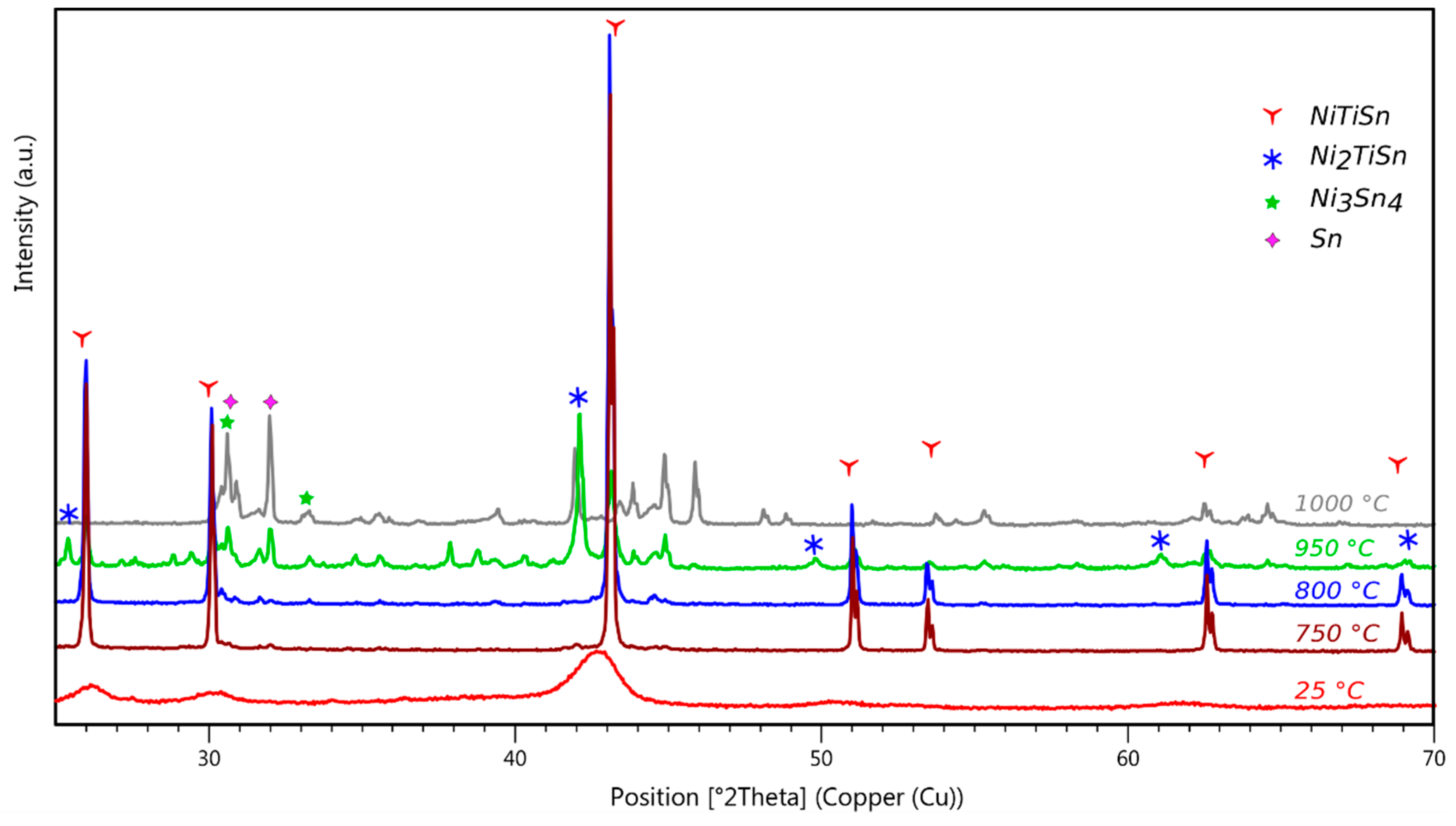
3.5.1. Annealing Temperature

Let us analyze several fractions of a same sample separately annealed at various temperatures to evaluate the influence of the temperature level on the final material. A sample from MA at 600 rpm for 5 h was chosen to illustrate this effect and characterized, prior to annealing, as mainly composed of NiTiSn. Sample fractions were annealed for 10 days at temperatures from 750 to 1000 °C, lower than the peritectic decomposition of NiTiSn [7,62]. The XRD patterns of the annealed samples (Figure 8) are characterized by sharp and intense diffraction lines pointing out the good crystallinity of the material.
At first glance, the material annealed at 750 °C displays the highest quality. Actually, Rietveld analyses bring the confirmation that it is composed of NiTiSn at 97%, but also contains traces of Ni2TiSn and Sn (in equivalent quantities). The samples annealed at higher temperatures are characterized by weaker amounts of NiTiSn.
As the annealing temperature level increases, the material becomes more and more multiphasic, decomposing progressively into binary phases, and releasing free Sn. Some oxygen incorporation, most probably from the silica container (a very local reaction could have been initiated at the contact point between the sample and the silica tube during the heat treatment), has even been observed for samples annealed at 1000 °C in which some diffraction lines have been assigned to the ternary oxide Ni3Ti3O [83,84]. This result is partially consistent with a previous theoretical work predicting the decomposition of NiTiSn in the presence of oxygen to give oxides and nickel stannides [61]. However, titanium oxides like Ti2O3 are expected rather than Ni3Ti3O (not considered in the study and which may be formed at high temperature).
For all the samples prepared by high energy MA (500 rpm and beyond) and later annealed, results are very similar. For a given energy, 750 °C is the temperature of annealing which leads to the highest purity of the final material. The best quality is obtained for samples prepared with the shortest reaction time of 5 h.
Likewise, the best annealing temperature is 750 °C for samples prepared at 400 rpm. Reminding that these samples are multiphasic and mainly composed of Ni3Sn4, it is quite surprising that the annealed material is fairly pure NiTiSn with only traces of free Sn (composition was evidenced from XRD and confirmed by EDX measurements). As described above, the Sn amount also increases in samples annealed at 850 °C where the degradation is even more important, with the occurrence again of binary phases in samples annealed at 950 °C and oxides (diffraction lines of Ni3Ti3O) in samples annealed at 1000 °C. In this case, the annealing treatment proceeds through conversion of a multiphasic solid into a nearly single-phase material. Interestingly, such a conversion occurs for all the samples alloyed at 400 rpm regardless of the MA time (Figure 9) and the annealed materials still mainly contain NiTiSn with a purity of ~85% for the longest alloying reaction of 43 h.

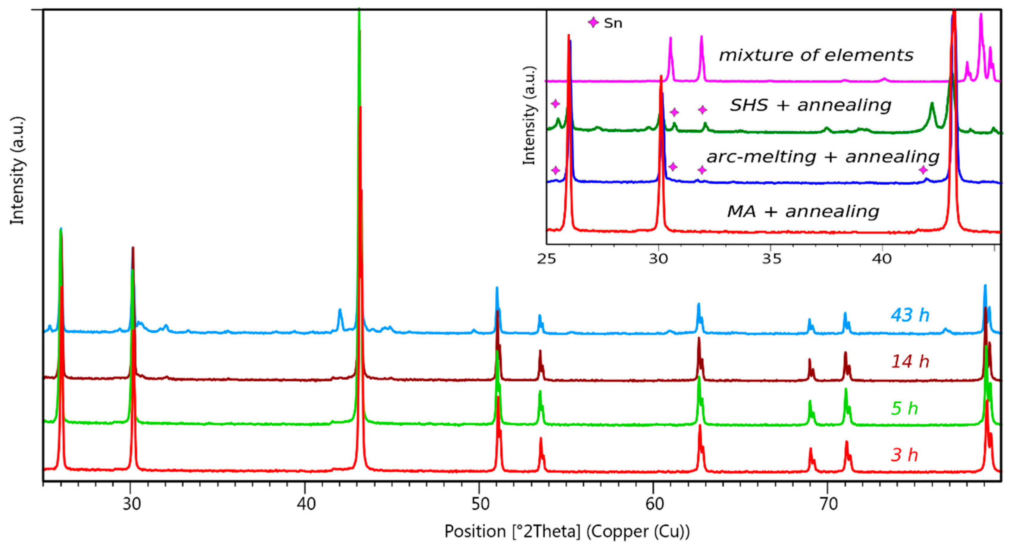
3.5.2. Annealing Duration

Parallel annealing of sample fractions have proved that a thermal treatment for only 5 days is not long enough to obtain a high quality material. As indicated by the XRD patterns of the annealed samples, a quality improvement is obvious after 10 days, whereas no main quality modification could be detected for longer annealing periods (up to 15 days).
The influence of the annealing time is illustrated by the XRD patterns of fractions annealed at 800 °C for 5, 10, and 15 days starting from a sample alloyed at 700 rpm for 5 h (Figure S6, Supplementary Material).
The analysis of annealed materials from samples shortly alloyed at 400 rpm (parted into aggregates and powder) is of interest to improve our comprehension of the reaction mechanism. Thermal treatment of the aggregates led to fairly pure NiTiSn in which, however, remains residual Sn both observed by XRD and EDX. Instead, the annealing of the powder provided a highly pure NiTiSn material (Figure 10) in which no tin could be detected in spite of a thorough analysis of the SEM images because it has been trapped inside the aggregates (powder around tin seeds) at the beginning of the reaction.

4. Concluding Remarks

To conclude this study, let us summarize the major results.
The main finding is the existence of an energy window to directly obtain the half-Heusler NiTiSn compound by mechanical alloying. This energy window corresponds to rotation speeds of the ball mill between 500 and 700 rpm. After a subsequent annealing, the material reaches similar purity levels as materials prepared by arc-melting methods, still containing traces of tin. This means that direct preparation of NiTiSn through MA is not necessarily the best way to obtain a high purity material.
Outside of this window, materials do not contain NiTiSn anymore but a mixture of binary compounds, which can be subsequently converted into NiTiSn by thermal treatment. The best path towards pure NiTiSn consists in such a conversion process from a multiphasic precursor into a single-phase material. After removal of the aggregates, highly pure NiTiSn without residual tin, was obtained this way.
From the post processing of samples mechanically alloyed in various conditions, the optimal annealing treatment to obtain pure NiTiSn was found to be 750 °C for 10 days.
The short peculiar experiments conducted at 400 rpm have been very useful to interpret the phenomena during the early stages of alloying and enabled us to propose a mechanism of formation of the multicomponent precursor which is supported by the calculated (DFT) formation enthalpies.

Supplementary Materials

The following are available online at https://www.mdpi.com/2075-4701/8/10/835/s1, Figure S1: XRD for a mixture of Ni, Ti, Sn powders after thermal treatment at 850 °C for 30 days; Figure S2: SEM image of a sample alloyed at 800 rpm for 5 h; Figure S3: XRD for samples prepared by MA for 14 h; Figure S4: XRD for samples alloyed at 500 rpm; Figure S5: SEM image of the aggregates recovered in samples alloyed at 400 rpm; Figure S6: XRD for samples prepared by MA at 700 rpm for 5 h and subsequently annealed at 800 °C; Table S1: Indexation of the diffraction lines for NiTiSn and Ni2TiSn Table S2. Formation enthalpies calculated for the compounds in the NiTiSn system.

Author Contributions

Study conceptualization, M.T. and P.J.; experiments, M.T.; Calculations, M.T. and A.B. The manuscript was written through contributions of all authors. All authors have given approval to the final version of the manuscript.

Funding

This research received no external funding.

Acknowledgments

We would like to thank V. Monino for his contribution to this work during a student internship in the frame of his Master’s degree and F. Rouessac for the self-propagating high-temperature synthesis.

Conflicts of Interest

The authors declare no conflict of interest.

References

  1. Graf, T.; Felser, C.; Parkin, S.S.P. Simple rules for the understanding of Heusler compounds. Prog. Solid State Chem. 2011, 39, 1–50. [Google Scholar] [CrossRef]
  2. Aliev, F.G.; Brandt, N.B.; Moshchalkov, V.V.; Kozyrkov, V.V.; Skolozdra, R.V.; Belogorokhov, A.I. Gap at the Fermi level in the intermetallic vacancy system RNiSn (R = Ti, Zr, Hf). Z. Phys. B Condens. Matter 1989, 75, 167–171. [Google Scholar] [CrossRef]
  3. Aliev, F.G.; Kozyrkov, V.V.; Moshchalkov, V.V.; Scolozdra, R.V.; Durczewski, K. Narrow band in the intermetallic compounds MNiSn (M = Ti, Zr, Hf). Z. Phys. B Condens. Matter 1990, 80, 353–357. [Google Scholar] [CrossRef]
  4. Katayama, T.; Kim, S.W.; Kimura, Y.; Mishismai, Y. The effects of quaternary additions on thermoelectric properties of TiNiSn-based half-Heusler alloys. J. Electron. Mater. 2003, 32, 1160–1165. [Google Scholar] [CrossRef]
  5. Zou, M.; Li, J.-F.; Dua, B.; Liu, D.; Kita, T. Fabrication and thermoelectric properties of fine-grained TiNiSn compounds. J. Solid State Chem. 2009, 182, 3138–3142. [Google Scholar] [CrossRef]
  6. Joshi, G.; Yan, X.; Wang, H.; Liu, W.; Chen, G.; Ren, Z. Enhancement in thermoelectric figure-of-merit of an n-type half-Heusler compound by the nanocomposite approach. Adv. Energy Mater. 2011, 1, 643–647. [Google Scholar] [CrossRef]
  7. Jung, D.-Y.; Kurosaki, K.; Kim, C.-E.; Muta, H.; Yamanaka, S. Thermal expansion and melting temperature of the half-Heusler compounds: MNiSn (M = Ti, Zr, Hf). J. Alloys Compd. 2010, 489, 328–331. [Google Scholar] [CrossRef]
  8. Birkel, C.S.; Douglas, J.E.; Lettiere, B.R.; Seward, G.; Zhang, Y.; Pollock, T.M.; Seshadri, R.; Stucky, G.D. Influence of Ni nanoparticle addition and spark plasma sintering on the TiNiSn-Ni system: Structure, microstructure, and thermoelectric properties. Solid State Sci. 2013, 26, 16–22. [Google Scholar] [CrossRef]
  9. Chai, Y.W.; Kimura, Y. Microstructure evolution of nanoprecipitates in half-Heusler TiNiSn alloys. Acta Mater. 2013, 61, 6684–6697. [Google Scholar] [CrossRef]
  10. Hermet, P.; Niedziolka, K.; Jund, P. A first-principles investigation of the thermodynamic and mechanical properties of Ni–Ti–Sn Heusler and half-Heusler materials. RSC Adv. 2013, 3, 22176–22184. [Google Scholar] [CrossRef]
  11. Romaka, V.V.; Rogl, P.; Romaka, L.P.; Stadnyk, Y.V.; Melnychenko, N.O.; Grytsiv, A.V.; Falmbigl, M.; Skryabina, N.E. Phase equilibria, formation, crystal and electronic structure of ternary compounds in Ti-Ni-Sn and Ti-Ni-Sb ternary systems. J. Solid State Chem. 2013, 197, 103–112. [Google Scholar] [CrossRef]
  12. Rogl, G.; Grytsiv, A.; Gürth, M.; Tavassoli, A.; Ebner, C.; Wünschek, A.; Puchegger, S.; Soprunyuk, V.; Schranz, W.; Bauer, E.; et al. Mechanical properties of half-Heusler alloys. Acta Mater. 2016, 107, 178–195. [Google Scholar] [CrossRef]
  13. Birkel, C.S.; Douglas, J.E.; Lettiere, B.R.; Seward, G.; Verma, N.; Zhang, Y.; Pollock, T.M.; Seshadri, R.; Stucky, G.D. Improving the thermoelectric properties of half-Heusler TiNiSn through inclusion of a second full-Heusler phase: Microwave preparation and spark plasma sintering of TiNi1+xSn. Phys. Chem. Chem. Phys. 2013, 15, 6990–6997. [Google Scholar] [CrossRef] [PubMed]
  14. Gelbstein, Y.; Tal, N.; Yarmek, A.; Rosenberg, Y.; Dariel, M.P.; Ouardi, S.; Balke, B.; Felser, C.; Köhne, M. Thermoelectric properties of spark plasma sintered composites based on TiNiSn half-Heusler alloys. J. Mater. Res. 2011, 26, 1919–1924. [Google Scholar] [CrossRef]
  15. Jager, T. Thermoelectric Properties of TiNiSn and Zr0.5Hf0.5NiSn Thin Films and Superlattices with Reduced Thermal Conductivities. Ph.D. Thesis, Johannes Gutenberg-Universität Mainz, Mainz, Germany, 2013. [Google Scholar]
  16. Birkel, C.S.; Zeier, W.G.; Douglas, J.E.; Lettiere, B.R.; Mills, C.E.; Seward, G.; Birkel, A.; Snedaker, M.L.; Zhang, Y.; Snyder, G.J.; et al. Rapid microwave preparation of thermoelectric TiNiSn and TiCoSb half-Heusler compounds. Chem. Mater. 2012, 24, 2558–2565. [Google Scholar] [CrossRef]
  17. Lei, Y.; Li, Y.; Xu, L.; Yang, J.; Wan, R.; Long, H. Microwave synthesis and sintering of TiNiSn thermoelectric bulk. J. Alloys Compd. 2016, 660, 166–170. [Google Scholar] [CrossRef]
  18. Suryanarayana, C.; Ivanov, E.; Boldyrev, V.V. The science and technology of mechanical alloying. Mater. Sci. Eng. A 2001, 304–306, 151–158. [Google Scholar] [CrossRef]
  19. Suryanarayana, C. Phase formation under non-equilibrium processing conditions: Rapid solidification processing and mechanical alloying. J. Mater. Sci. 2018, 53, 13364–13379. [Google Scholar] [CrossRef]
  20. Le Brun, P.; Froyen, L.; Delaey, L. The modelling of the mechanical alloying process in a planetary ball mill: Comparison between theory and in-situ observations. Mater. Sci. Eng. A Struct. 1993, 161, 75–82. [Google Scholar] [CrossRef]
  21. Soban, B.; Gaffet, E. Mechanosynthesis: An Improved Mathematical Contribution to the Planetary Ball Mill Kinematics. Available online: https://www.researchgate.net/publication/256228753_Mechanosynthesis_An_improved_mathematical_contribution_to_the_planetary_ball_mill_kinematics (accessed on 1 September 2018).
  22. Delogu, F.; Takacs, L. Information on the mechanism of mechanochemical reaction from detailed studies of the reaction kinetics. J. Mater. Sci. 2017, 53, 13331–13342. [Google Scholar] [CrossRef]
  23. Skakov, Y.A. Metastable phase state during mechanical alloying. Sci. Sinter. 2005, 37, 131–138. [Google Scholar] [CrossRef]
  24. Dreizin, E.L.; Schoenitz, M. Mechanochemically prepared reactive and energetic materials: A review. J. Mater. Sci. 2017, 52, 11789–11809. [Google Scholar] [CrossRef]
  25. Suryanarayana, C. Mechanical alloying and milling. Prog. Mater Sci. 2001, 46, 1–184. [Google Scholar] [CrossRef]
  26. El-Eskandarany, M.S. Mechanical Alloying for Fabrication of Advanced Engineering Materials; Noyes Publications/William Andrew Publishing: Norwich, NY, USA, 2001. [Google Scholar]
  27. Takacs, L. The historical development of mechanochemistry. Chem. Soc. Rev. 2013, 42, 7649–7659. [Google Scholar] [CrossRef] [PubMed]
  28. Abenojar, J.; Velasco, F.; Mota, J.M.; Martínez, M.A. Preparation of Fe/B powders by mechanical alloying. J. Solid State Chem. 2004, 177, 382–388. [Google Scholar] [CrossRef]
  29. Abu, M.J.; Mohamed, J.J.; Ahmad, Z.A. Synthesis of high purity titanium silicon carbide from elemental powders using arc melting method. Int. J. Refract. Met. Hard Mater. 2014, 47, 86–92. [Google Scholar] [CrossRef]
  30. Padyukov, K.L.; Levashov, E.A. Self-propagating high-temperature synthesis: A new method for the production of diamond-containing materials. Diamond Relat. Mater. 1993, 2, 207–210. [Google Scholar] [CrossRef]
  31. Ipus, J.J.; Blázquez, J.S.; Franco, V.; Millán, M.; Conde, A.; Oleszak, D.; Kulik, T. An equivalent time approach for scaling the mechanical alloying processes. Intermetallics 2008, 16, 470–478. [Google Scholar] [CrossRef]
  32. Petricek, V.; Dusek, M.; Palatinus, L. Crystallographic computing system JANA2006: General features. Z. Kristallogr. Cryst. Mater. 2014, 229, 345–352. [Google Scholar] [CrossRef]
  33. Density Functional Theory. Available online: https://en.wikipedia.org/wiki/Density_functional_theory (accessed on 28 September 2018).
  34. Perdew, J.P.; Burke, K.; Ernzerhof, M. Generalized Gradient Approximation Made Simple. Phys. Rev. Lett. 1996, 77, 3865–3868. [Google Scholar] [CrossRef] [PubMed]
  35. Perdew, J.P.; Burke, K.; Ernzerhof, M. Erratum: Generalized Gradient Approximation Made Simple. Phys. Rev. Lett. 1996, 78, 1396. [Google Scholar] [CrossRef]
  36. Monkhorst, H.J.; Pack, J.D. Special points for Brillouin-zone integrations. Phys. Rev. B 1976, 13, 5188–5192. [Google Scholar] [CrossRef]
  37. Gladyshevskii, E.I.; Markiv, V.Y.; Kuz’ma, Y.B.; Cherkashyn, E.E. Crystal structure of some ternary intermetallic titanium compounds. Titanium Its Alloys Engl. Transl. 1966, 10, 73–75. [Google Scholar]
  38. Romaka, V.A.; Stadnyk, Y.V.; Fruchart, D.; Romaka, V.V.; Rogl, P.; Davydov, V.M.; Gorelenko, Y.K.; Goryn’, A.M. Investigation of the mechanisms of local amorphization in a heavily doped crystalline semiconductor n-TiNiSn. Ukrayins’ kij Fyizichnij Zhurnal (Kyiv) 2008, 53, 42–49. [Google Scholar]
  39. Nowotny, H.; Schubert, K. Die kristallstruktur von Ni3Sn4. Naturwissenschaften 1944, 32, 76b. [Google Scholar] [CrossRef]
  40. Bhargava, M.K.; Schubert, K. Kristallstruktur von NiSn. J. Less-Common Met. 1973, 33, 181–189. [Google Scholar] [CrossRef]
  41. Fjellvag, H.; Kjekshus, A. Structural properties of Co3Sn2, Ni3Sn2 and some ternary derivatives. Acta Chem. Scand. A 1986, 40, 23–30. [Google Scholar] [CrossRef]
  42. Rahlfs, P. Die kristallstruktur des Ni3Sn (Mg3Cd-Typ: Überstruktur der hexagonal dichtesten kugelpackung). Metallwirtsch. Metallwiss. Metalltech. 1937, 16, 343–345. [Google Scholar]
  43. Kleinke, H.; Waldeck, M.; Gütlich, P. Ti2Sn3: A novel binary intermetallic phase, prepared by chemical transport at intermediate temperature. Chem. Mater. 2000, 12, 2219–2224. [Google Scholar] [CrossRef]
  44. Schubert, K.; Frank, K.; Gohle, R.; Maldonado, A.; Meissner, H.G.; Raman, A.; Rossteutscher, W. Einige strukturdaten metallischer phasen. Naturwissenschaften 1963, 50, 41. [Google Scholar] [CrossRef]
  45. Pietrokowsky, P.; Duwez, P.E. Crystal structure of Ti5Si3, Ti5Ge3, and Ti5Sn3. Trans. Am. Inst. Min. Metall. Pet. Eng. 1951, 191, 772–773. [Google Scholar] [CrossRef]
  46. Banumathy, S.; Singh, A.K. Rietveld refinement of the A3B (D019) and A2B (B82) phases in Ti-Sn and Ti-Ga alloys. Intermetallics 2011, 19, 1594–1598. [Google Scholar] [CrossRef]
  47. Pietrokowsky, P. Crystal Structure of Ti3Sn. Trans. Am. Inst. Min. Metall. Pet. Eng. 1952, 194, 211–212. [Google Scholar] [CrossRef]
  48. Yurko, G.A.; Barton, J.W.; Parr, J.G. The crystal structure of Ti2Ni. Acta Crystallogr. 1959, 12, 909–911. [Google Scholar] [CrossRef]
  49. Bührer, W.; Gotthardt, R.; Kulik, A.V.; Mercier, O.; Staub, F. Powder neutron diffraction study of nickel-titanium martensite. J. Phys. F Met. Phys. 1983, 13, L77–L81. [Google Scholar] [CrossRef]
  50. Michal, G.M.; Sinclair, R. The structure of TiNi martensite. Acta Crystallogr. B 1981, 37, 1803–1807. [Google Scholar] [CrossRef] [Green Version]
  51. Saburi, T.; Nenno, S.; Fukuda, T. Crystal structure and morphology of the metastable X phase in shape memory Ti-Ni alloys. J. Less-Common Met. 1986, 125, 157–166. [Google Scholar] [CrossRef]
  52. Laves, F.; Wallbaum, H.J. Die Kristallstruktur von Ni3Ti und Si2Ti (zwei neue Typen). Z. Kristallogr. Cryst. Mater. 1939, 101, 78–93. [Google Scholar] [CrossRef]
  53. Hull, A.W. X-ray crystal analysis of thirteen common metals. Phys. Rev. B 1921, 17, 571–588. [Google Scholar] [CrossRef]
  54. Mark, H.; Polanyl, M. Die Gitterstruktur, Gleitrichtungen und Gleitebenen des weissen Zinns. Z. Phys. 1923, 18, 75–96. [Google Scholar] [CrossRef]
  55. Kresse, G.; Forthmüller, J. Efficiency of ab-initio total energy calculations for metals and semiconductors using a plane-wave basis set. Comput. Mater. Sci. 1996, 6, 15–50. [Google Scholar] [CrossRef]
  56. Kresse, G.; Forthmüller, J. Efficient iterative schemes for ab initio total-energy calculations using a plane-wave basis set. Phys. Rev. B 1996, 54, 11169–11186. [Google Scholar] [CrossRef]
  57. Vanderbilt, D. Soft self-consistent pseudopotentials in a generalized eigenvalue formalism. Phys. Rev. B 1990, 41, 7892–7895. [Google Scholar] [CrossRef]
  58. Kresse, G.; Joubert, D. From ultrasoft pseudopotentials to the projector augmented-wave method. Phys. Rev. B 1999, 59, 1758–1775. [Google Scholar] [CrossRef]
  59. Blöchl, P.E. Projector augmented-wave method. Phys. Rev. B. 1994, 50, 17953–17979. [Google Scholar] [CrossRef] [Green Version]
  60. Dudarev, S.L.; Botton, G.A.; Savrasov, S.Y.; Humphreys, C.J.; Sutton, A.P. Electron-energy-loss spectra and the structural stability of nickel oxide: An LSDA+U study. Phys. Rev. B. 1988, 57, 1505–1509. [Google Scholar] [CrossRef]
  61. Berche, A.; Jund, P. Oxidation of half-Heusler NiTiSn materials: Implications for thermoelectric applications. Intermetallics 2018, 92, 62–71. [Google Scholar] [CrossRef]
  62. Douglas, J.E.; Birkel, C.S.; Verma, N.; Miller, V.M.; Miao, M.-S.; Stucky, G.D.; Pollock, T.M.; Seshadri, R. Phase stability and property evolution of biphasic Ti–Ni–Sn alloys for use in thermoelectric applications. J. Appl. Phys. 2014, 115, 043720. [Google Scholar] [CrossRef] [Green Version]
  63. Downie, R.A.; MacLaren, D.A.; Smith, R.I.; Bos, J.W.G. Enhanced thermoelectric performance in TiNiSn-based half-Heuslers. Chem. Commun. 2013, 49, 4184–4186. [Google Scholar] [CrossRef] [PubMed]
  64. Berche, A.; Tédenac, J.C.; Fartushna, J.; Jund, P. Calphad assessment of the Ni–Sn–Ti system. Calphad 2016, 54, 67–75. [Google Scholar] [CrossRef]
  65. Gürth, M.; Grytsiv, A.; Vrestal, J.; Romaka, V.V.; Giester, G.; Bauer, E.; Rogl, P. On the constitution and thermodynamic modelling of the system Ti–Ni–Sn. RSC Adv. 2015, 5, 92270–92291. [Google Scholar] [CrossRef]
  66. Zou, M.; Li, J. Fabrication of TiNiSn-Based Half-Heusler Thermoelectric Compound by Mechanical Alloying and Spark Plasma Sintering. Rare Met. Mater. Eng. 2009, 38, 1079–1082. [Google Scholar]
  67. Flandorfer, H.; Saeed, U.; Luef, C.; Sabbar, A.; Ipser, H. Interfaces in lead-free solder alloys: Enthalpy of formation of binary Ag–Sn, Cu–Sn and Ni–Sn intermetallic compounds. Thermochim. Acta 2007, 459, 34–39. [Google Scholar] [CrossRef]
  68. Guo, Q.; Kleppa, O.J. Standard enthalpies of formation of some alloys formed between group IV elements and group VIII elements, determined by high-temperature direct synthesis calorimetry: II. Alloys of (Ti, Zr, Hf) with (Co, Ni). J. Alloys Compd. 1998, 269, 181–186. [Google Scholar] [CrossRef]
  69. Meschel, S.V.; Kleppa, O.J. Standard enthalpies of formation of some 3d, 4d and 5d transition-metal stannides by direct synthesis calorimetry. Thermochim. Acta 1998, 314, 205–212. [Google Scholar] [CrossRef]
  70. Moser, Z.; Gasior, W.; Rzyman, K.; Debski, A. Calorimetric Studies of the Enthalpies of Formation of NiTi2, NiTi and Ni3Ti. Arch. Metall. Mater. 2006, 51, 605–608. [Google Scholar]
  71. Predel, B.; Ruge, H. Bildungsenthalpien und bindungsverhältnisse in einigen intermetallischen verbindungen vom NiAs-Typ. Thermochim. Acta 1972, 3, 411–419. [Google Scholar] [CrossRef]
  72. Predel, B.; Vogelbein, W. Bildungsenthalpien fester legierungen der binären systeme des eisens, kobalts und nickels mit germanium und zinn. Thermochim. Acta 1979, 30, 201–215. [Google Scholar] [CrossRef]
  73. Vassiliev, G.P.; Liloa, K.I.; Gachon, J.C. Enthalpies of formation of Ni–Sn compounds. Thermochim. Acta 2006, 447, 106–108. [Google Scholar] [CrossRef]
  74. Yin, M.; Nash, P. Standard enthalpies of formation of selected XYZ half-Heusler compounds. J. Chem. Thermodyn. 2015, 91, 1–7. [Google Scholar] [CrossRef]
  75. Yin, M.; Nash, P. Standard enthalpies of formation of selected Ni2YZ Heusler compounds. J. Alloys Compd. 2016, 660, 258–265. [Google Scholar] [CrossRef]
  76. Offernes, L.; Ravindran, P.; Seim, C.W.; Kjekshus, A. Prediction of composition for stable half-Heusler phases from electronic-band-structure analyses. J. Alloys Compd. 2008, 458, 47–60. [Google Scholar] [CrossRef]
  77. Muta, H.; Kanemitsu, T.; Kurosaki, K.; Yamanaka, S. High-temperature thermoelectric properties of Nb-doped MNiSn (M = Ti, Zr) half-Heusler compound. J. Alloys Compd. 2009, 469, 50–55. [Google Scholar] [CrossRef]
  78. Ke, S.; Pan, Z.; Wang, Y.; Ning, C.; Zheng, S.; Huang, J. Effect of mechanical activation on solid-state synthesis process of neodymium disilicate ceramic pigment. Dyes Pigments 2017, 145, 160–167. [Google Scholar] [CrossRef]
  79. Mostaan, H.; Mehrizi, M.Z.; Rafiei, M.; Beygi, R.; Abbasian, A.R. Contribution of mechanical activation and annealing in the formation of nanopowders of Al(Cu)/TiC-Al2O3 hybrid nanocomposite. Ceram. Int. 2017, 43, 2680–2685. [Google Scholar] [CrossRef]
  80. Bernard, F.; Paris, S.; Gaffet, E. Mechanical Activation as a New method for SHS. Adv. Sci. Technol. 2006, 45, 979–988. [Google Scholar] [CrossRef]
  81. Streletskii, A.N.; Sivak, M.V.; Dolgoborodov, A.Y. Nature of high reactivity of metal/solid oxidizer nanocomposites prepared by mechanoactivation: A review. J. Mater. Sci. 2017, 52, 11810–11825. [Google Scholar] [CrossRef]
  82. Takacs, L. Self-sustaining reactions induced by ball milling. Prog. Mater. Sci. 2002, 47, 355–414. [Google Scholar] [CrossRef]
  83. Posnjak, E.; Barth, T.F.W. Notes on some structures of the ilmenite type. Z. Kristallogr. Cryst. Mater. 1934, 88, 271. [Google Scholar] [CrossRef]
  84. Karlsson, N. Metallic Oxides with the Structure of High-speed Steel Carbide. Nature 1951, 168, 558. [Google Scholar] [CrossRef]
Figure 1. SEM micrograph of an arc-melted sample and profile fitting of its XRD pattern (CuKα, 4-components Ti6Sn5, Ni2TiSn, Sn, and NiTiSn, from top to bottom, Rp = 3.4, wRp = 4.7, GoF = 1.9) after 10 days of annealing at 750 °C.
Metals 08 00835 g001
Figure 2. XRD patterns for samples prepared by MA during 5 h. Energy provided to samples varies with rotation speed taken from 300 to 800 rpm. The pattern for the stoichiometric Ni:Ti:Sn mixture before MA is drawn at the bottom, and the simulated pattern for the cubic NiTiSn half-Heusler compound at the top.
Metals 08 00835 g002
Figure 3. XRD patterns for samples prepared by MA during 43 h. Provided energy varies with rotation speed taken from 400 to 700 rpm.
Metals 08 00835 g003
Figure 4. XRD patterns for samples mechanically alloyed at 700 rpm during 5, 14, or 43 h.
Metals 08 00835 g004
Figure 5. Phase identification in a typical XRD pattern for a sample alloyed at 400 rpm for 5 h. The pattern of a stoichiometric Ni:Ti:Sn non-alloyed mixture is given at the bottom and the patterns of the powder and the aggregates are given in the inset.
Metals 08 00835 g005
Figure 6. XRD patterns for the powder and the aggregates collected in samples alloyed at 400 rpm. It is important to note that no aggregates are found after long reaction times (14–43 h*).
Metals 08 00835 g006
Figure 7. Calculated formation enthalpies (in kJ/mol of atom) for binary and ternary compounds in the Ni-Ti-Sn ternary diagram.
Metals 08 00835 g007
Figure 8. XRD patterns for samples prepared by MA at 600 rpm for 5 h and annealed for 10 days at temperatures from 750 to 1000 °C (25 °C corresponds to the non-annealed sample).
Metals 08 00835 g008
Figure 9. XRD patterns of samples prepared by MA at 400 rpm and annealed for 10 days at 750 °C. A comparison with other synthesis methods is given in the inset.
Metals 08 00835 g009
Figure 10. Experimental XRD pattern (λ = 1.5418 Å) of the powder from a sample prepared by MA at 400 rpm and annealed for 10 days at 750 °C. Full Rietveld refinement (lattice and atom positions) to Rp = 4.5, wRp = 6.2, GoF = 2.0, and RBragg = 0.4 confirms NiTiSn as the unique component (black marks: Bragg positions, black dots: Measured intensities, blue and red lines: Calculated and difference intensity plots).
Metals 08 00835 g010
Table 1. Crystallographic data for elements and compounds in the Ni-Ti-Sn system.
Compound System Space GroupLattice Parameters (Å,°)Ref.
Ni2TiSnCubicFm 3 ¯ ma = 6.10[37]
NiTiSnCubicF 4 ¯ 3ma = 5.93[38]
Ni2Ti2SnTetragonalP42/mnma = 6.81, c = 6.43[11]
NiTi5Sn3HexagonalP63/mcma = 8.18, c = 5.56[11]
Ni3Sn4MonoclinicC2/ma = 12.20, b = 4.05, c = 5.21, β = 105.03[39]
NiSnOrthorhombicPbama = 5.20, b = 24.45, c = 4.09[40]
Ni3Sn2OrthorhombicPnmaa = 7.12, b = 5.20 c = 8.16[41]
Ni3SnHexagonalP63/mmca = 5.27, c = 4.23[42]
Ti2Sn3OrthorhombicCmcea = 5.95, b = 19.96, c = 7.03[43]
Ti6Sn5HexagonalP63/mmca = 9.25, c = 5.69[44]
Ti5Sn3HexagonalP63/mcma = 8.05, c = 5.45[45]
Ti2SnHexagonalP63/mmca = 4.63, c = 5.67[46]
Ti3SnHexagonalP63/mmca = 5.92, c = 4.76[47]
NiTi2CubicFd 3 ¯ ma = 11.28[48]
NiTiMonoclinicP21/ma = 2.89, b = 4.11, c = 4.66, β = 98.10[49,50]
Ni4Ti3 (m)RhombohedralR 3 ¯ a = 11.24, c = 5.08[51]
Ni3TiHexagonalP63/mmca = 5.11, c = 8.30[52]
NiCubicFmm a = 3.54[53]
TiHexagonalP63/mmca = 2.94, c = 4.72[53]
SnTetragonalI41/amda = 5.84, c = 3.15[54]

