Novel Opposite Stirring Mode in Bloom Continuous Casting Mould by Combining Swirling Flow Nozzle with EMS


Abstract
:1. Introduction
2. Model Description
2.1. Assumptions
- (1)
- The molten steel flow in the mold cavity is a steady-state, incompressible flow process. The density, the viscosity, and the specific heat were assumed to be constant over temperature.
- (2)
- The influence of mold oscillation and mold curvature on the melt flow was not considered.
- (3)
- Flux or slag layer was considered on top of the molten metal free surface only for insulation.
- (4)
- The latent heat of the peritectic transformation and the joule heating generated by the induced current compared to the latent heat of fusion were considered to be negligible [12]. The mushy zone was treated as a porous medium, wherein the melt flow obeyed Darcy’s law.
- (5)
- The effect of melt flow on the electromagnetic field was ignored due to the small magnetic Reynolds number (about 0.01 [13]) in the stirring region.
- (6)
- The iron core of the stirrer was assumed to be magnetically linear with a constant permeability [13]. The cooling water jacket of the CC mold, the stainless steel protective jacket of the EMS, and the other insulation material in the EMS device were all simplified as a paramagnet in this model.
2.2. Macroscopic Transport Model
2.3. Solidification Model
2.4. VOF Model
2.5. Boundary Conditions and Computational Procedure
2.5.1. Boundary Conditions
2.5.2. Computational Procedure
3. Results and Discussions
3.1. Electromagnetic Field
3.2. Fluid Flow and Heat Transfer
3.3. Level Fluctuation and Flow Condition below the Meniscus
4. Conclusions
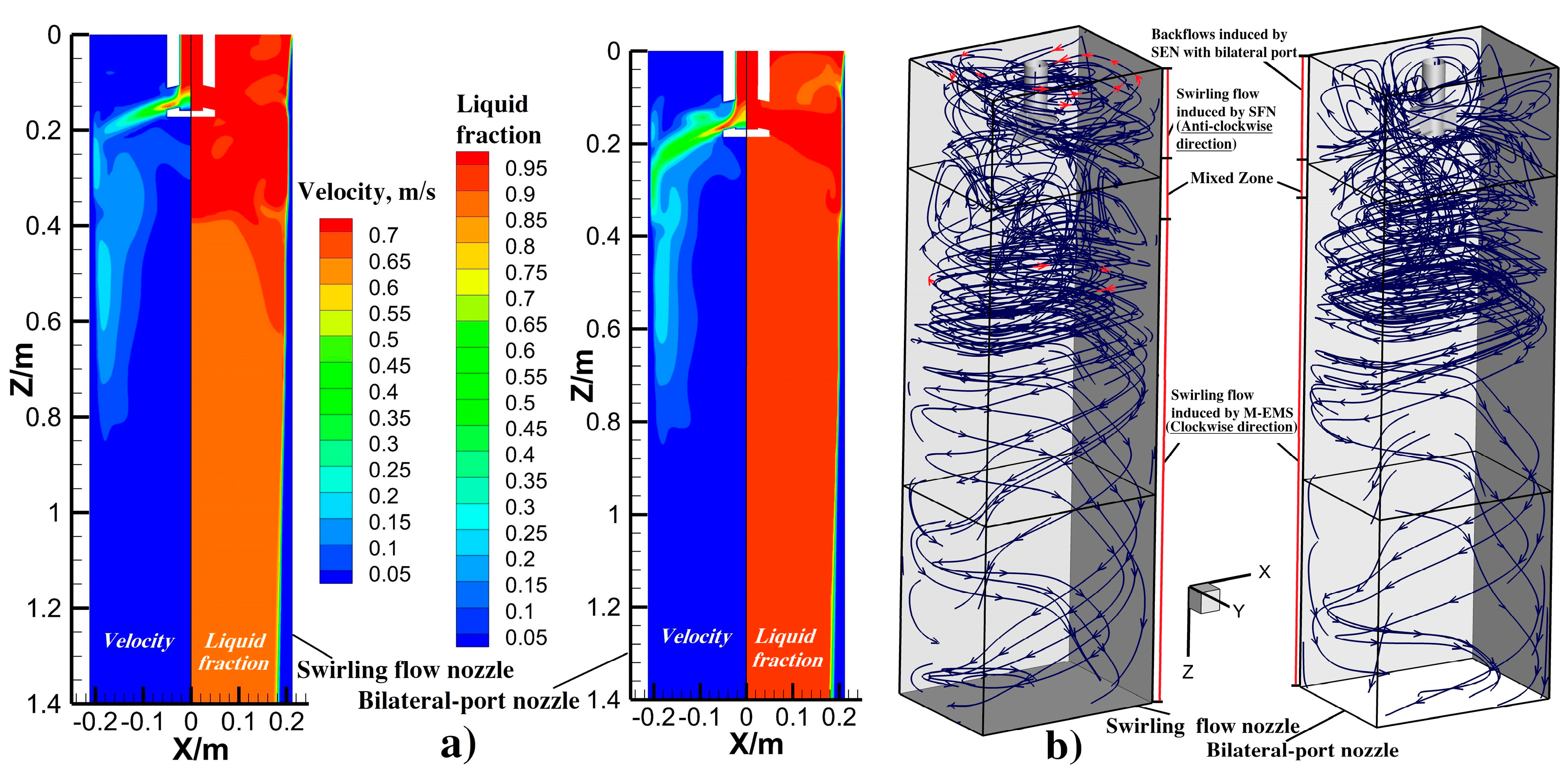
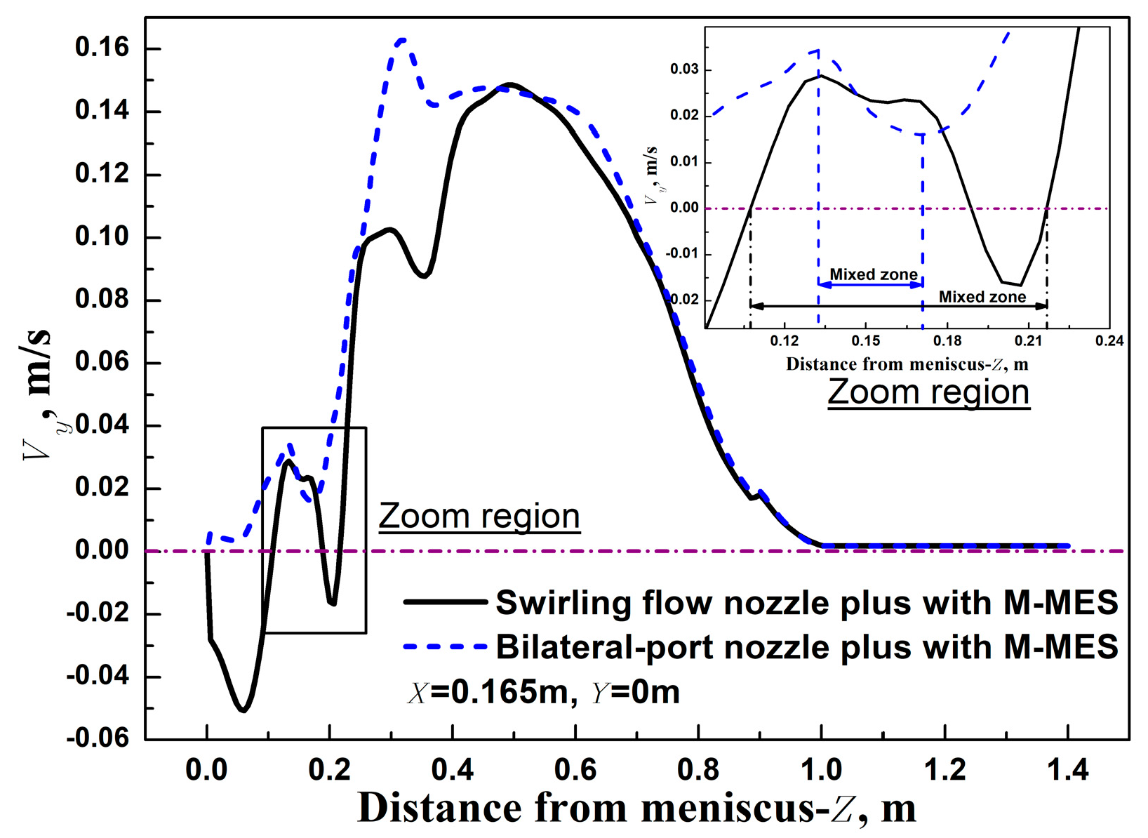
- The opposite stirring mode in the mold cavity can be formed by adopting SFN plus with M-EMS. Here, a swirling flow in the anti-clockwise direction generated by SFN, and the other swirling flow in the clockwise direction induced by M-EMS are observed at the areas with a distance ranging from 0 m to 0.11 m and 0.218 m to 1.4 m from the meniscus, respectively.
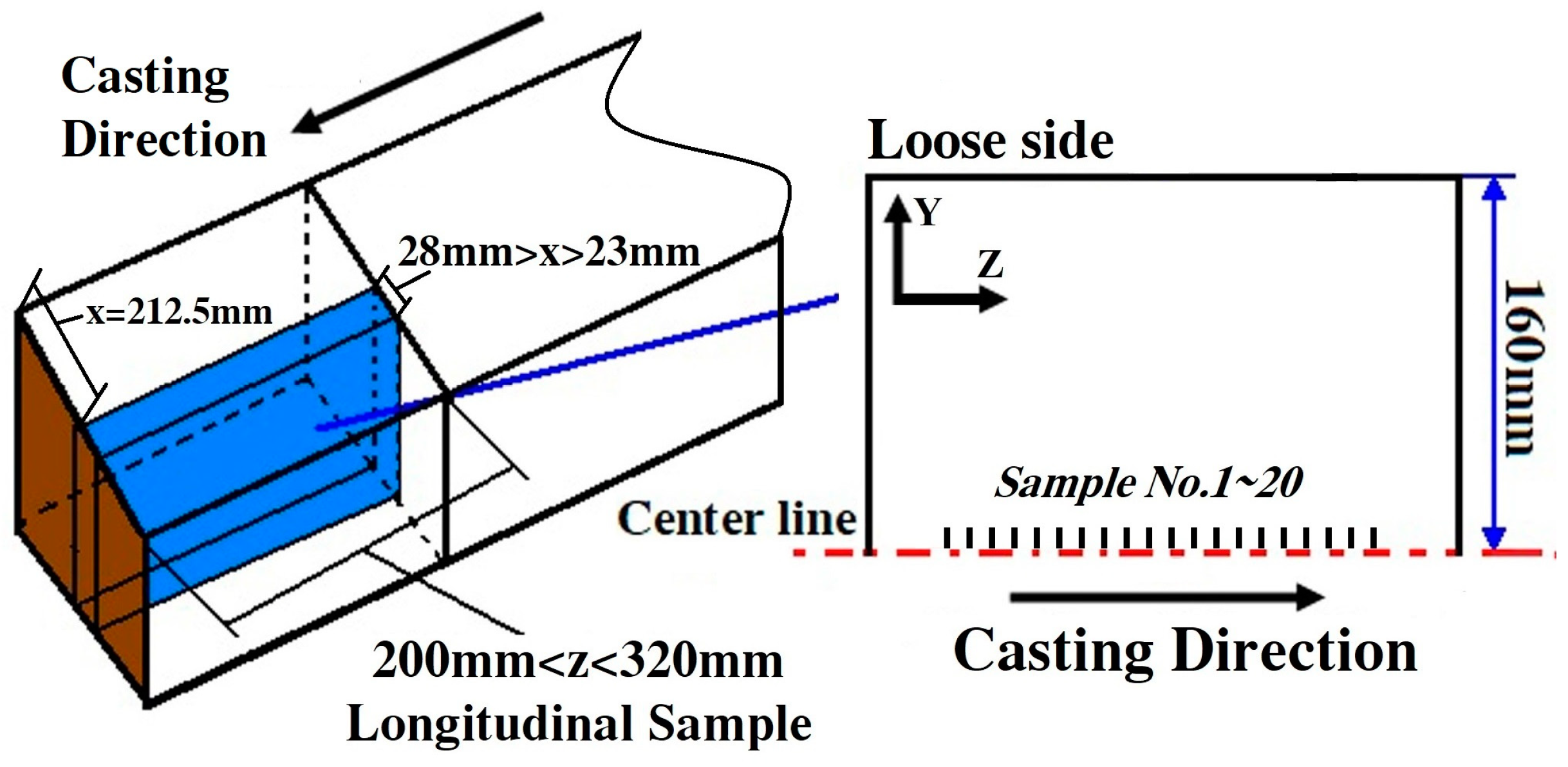
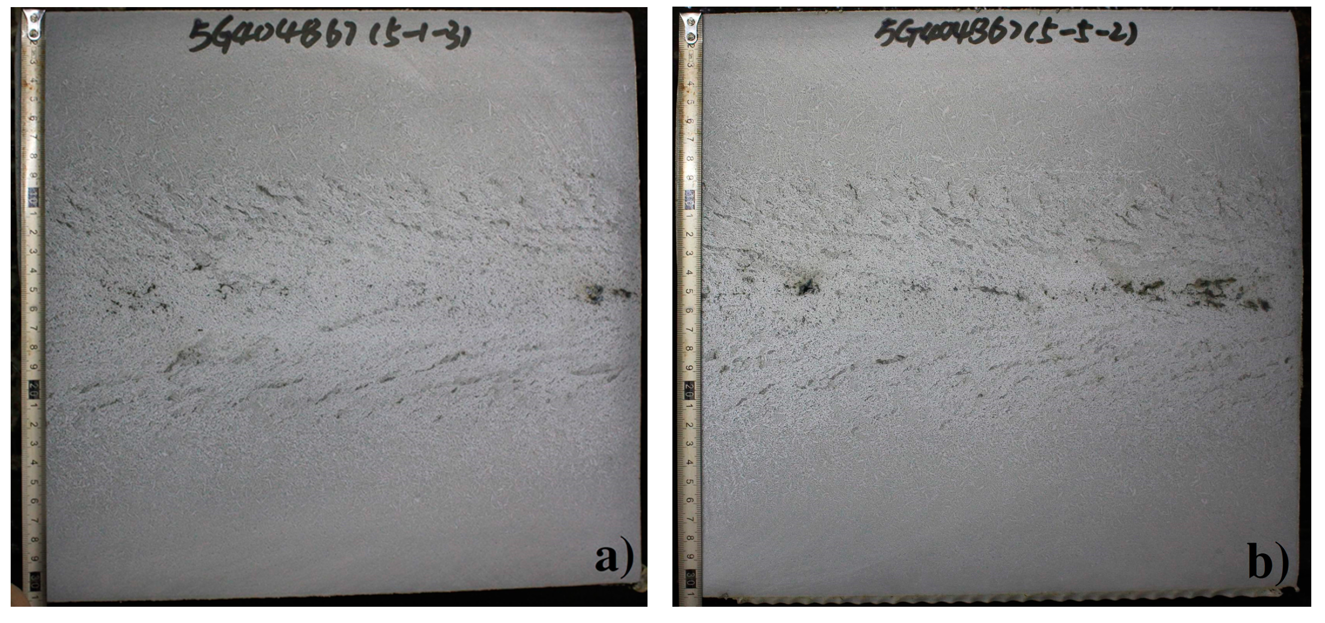
- As compared to the case of a bilateral-port nozzle plus with M-EMS, the soundness and centerline segregation of the as-cast bloom can be improved remarkably, and the fluctuation range of carbon segregation at the strand axis reduces from 0.16 to 0.06 because of the better superheat dissipation effect in the mold cavity by adopting the SFN plus with M-EMS.
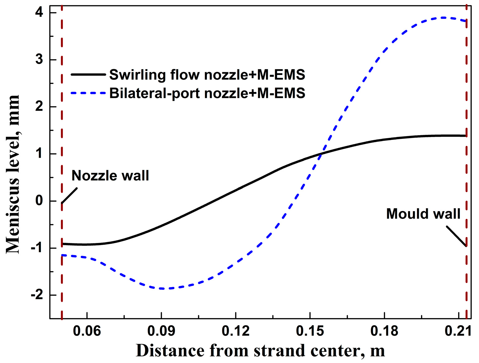
- The opposite stirring mode generated by the SFN plus with M-EMS can build a steady bulk flow below the meniscus in the mold cavity. The magnitude of mold level reduces from 5.6 mm to 2.3 mm, as compared to the case of the bilateral-port nozzle plus with M-EMS.
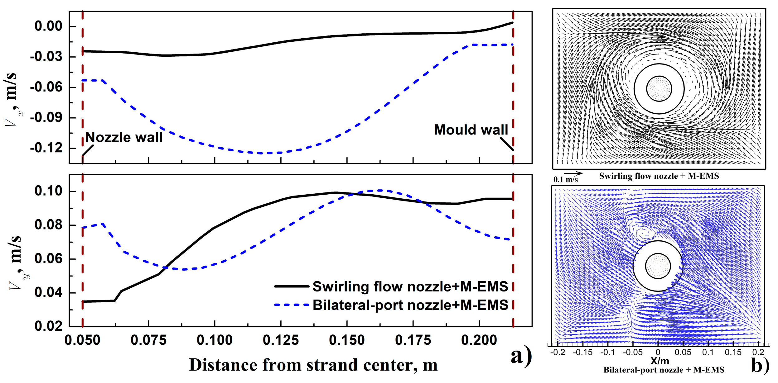
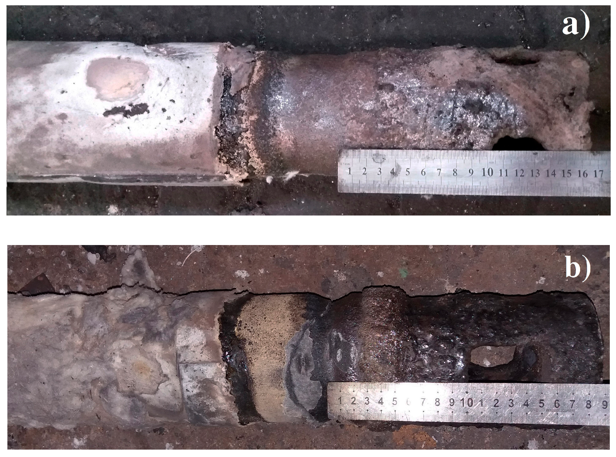
- The formation reason for the deep erosive slag line on the external wall of the bilateral-port nozzle can contribute to the higher meniscus level, the impact flow with a larger melt radial velocity, and the vortex flow near the nozzle wall when compared to the case of SFN plus with M-EMS.
Author Contributions
Funding
Acknowledgments
Conflicts of Interest
References
- Fang, Q.; Ni, H.; Zhang, H.; Zhang, H.; Ye, F. Effects of EMS induced flow on solidification and solute transport in bloom mold. Metals 2017, 7, 72. [Google Scholar] [CrossRef]
- Sun, H.; Zhang, J. Study on the macrosegregation behavior for the bloom continuous casting: Model development and validation. Metall. Mater. Trans. B 2014, 45, 1133–1149. [Google Scholar] [CrossRef]
- Kholmatov, S.; Takagi, S.; Jonsson, L.; Jonsson, P.; Yokoya, S. Development of flow field and temperature distribution during changing divergent angle of the nozzle when using swirl flow in a square continuous casting billet mould. ISIJ Int. 2007, 47, 80–87. [Google Scholar] [CrossRef]
- Tsukaguchi, Y.; Nakamura, O.; Jönsson, P.; Yokoya, S.; Tanaka, T.; Hara, S. Design of Swirling Flow Submerged Entry Nozzles for Optimal Head Consumption between Tundish and Mold. ISIJ Int. 2007, 47, 1436–1443. [Google Scholar] [CrossRef] [Green Version]
- Li, D.; Su, Z.; Chen, J.; Wang, Q.; Yang, Y.; Nakajiama, K.; Marukawa, K.; He, J. Effects of Electromagnetic Swirling Flow in Submerged Entry Nozzle on Square Billet Continuous Casting of Steel Process. ISIJ Int. 2013, 53, 1187–1194. [Google Scholar] [CrossRef] [Green Version]
- Li, D.; Su, Z.; Marukawa, K.; He, J. Simulation on effect of divergent angle of submerged entry nozzle on flow and temperature fields in round billet mold in electromagnetic swirling continuous casting process. J. Iron Steel Res. Int. 2014, 21, 159–165. [Google Scholar] [CrossRef]
- Svensson, J.K.S.; Memarpour, A.; Ekerot, S.; Brabie, V.; Jonsson, G. Studies of new coating materials to prevent clogging of submerged entry nozzle (SEN) during continuous casting of Al killed low carbon steels. Ironmak. Steelmak. 2017, 44, 117–127. [Google Scholar] [CrossRef]
- Mohammadi-Ghaleni, M.; Zaeem, M.A.; Smith, J.D.; O’Malley, R. Comparison of CFD simulations with experimental measurements of nozzle clogging in continuous casting of steels. Metall. Mater. Trans. B 2016, 47, 3384–3393. [Google Scholar] [CrossRef]
- Sun, H.; Zhang, J. Effect of feeding modes of molten steel on the mould metallurgical behavior for round bloom casting. ISIJ Int. 2011, 51, 1657–1663. [Google Scholar] [CrossRef]
- Sun, H.; Li, L. Application of swirling flow nozzle and investigation of superheat dissipation casting for bloom continuous casing. Ironmak. Steelmak. 2016, 43, 228–233. [Google Scholar] [CrossRef]
- Ludlow, V.; Normanton, A.; Anderson, A.; Thiele, M.; Ciriza, J.; Laraudogoitia, J.; Knoop, W.V. Strategy to minimise central segregation in high carbon steel grades during billet casting. Ironmak. Steelmak. 2005, 32, 68–74. [Google Scholar] [CrossRef]
- Fang, Q.; Ni, H.; Zhang, H.; Wang, B.; Lv, Z. The effects of a submerged entry nozzle on flow and initial solidification in a continuous casting bloom mold with electromagnetic stirring. Metals 2017, 7, 146. [Google Scholar] [CrossRef]
- Trindade, L.B.; Nadalon, J.E.A.; Contini, A.C.; Barroso, R.C. Modeling of Solidification in Continuous Casting Round Billet with Mold Electromagnetic Stirring (M-EMS). Steel Res. Int. 2017, 88, 1600319. [Google Scholar] [CrossRef]
- Liu, H.; Xu, M.; Qiu, S.; Zhang, H. Numerical simulation of fluid flow in a round bloom mold with in-mold rotary electromagnetic stirring. Metall. Mater. Trans. B 2012, 43, 1657–1675. [Google Scholar] [CrossRef]
- Zhang, H.; Ni, H.; Li, Y.; Zhao, Z. Numerical simulation on level fluctuation in bloom casting mold with electromagnetic stirring. In Proceedings of the Conference of the South African Advanced Materials Initiative, Vanderbijlpark, South Africa, 23–26 October 2018. [Google Scholar]
- Willers, B.; Barna, M.; Reiter, J.; Eckert, S. Experimental Investigations of Rotary Electromagnetic Mould Stirring in Continuous Casting Using a Cold Liquid Metal Model. ISIJ Int. 2017, 57, 468–477. [Google Scholar] [CrossRef] [Green Version]
- Hirayama, R.; Fujisaki, K. Combined system of AC and DC electromagnetic field for stabilized flow in continuous casting. IEEE Trans. Magn. 2005, 41, 4042–4044. [Google Scholar] [CrossRef]
- Hirayama, R.; Fujisaki, K.; Yamada, T. Dual in-mold electromagnetic stirring in continuous casting. IEEE Trans. Magn. 2004, 40, 2095–2097. [Google Scholar] [CrossRef]
- Cho, M.J.; Park, E.B.; Kim, S.W. Shield for improving wavy meniscus in the billet continuous casting mold with electromagnetic stirring. ISIJ Int. 2010, 50, 1180–1184. [Google Scholar] [CrossRef]
- Geng, X.; Li, X.F.; Liu, F.B.; Li, H.; Jiang, Z. Optimisation of electromagnetic field and flow field in round billet continuous casting mould with electromagnetic stirring. Ironmak. Steelmak. 2015, 42, 675–682. [Google Scholar] [CrossRef]
- Sun, H.; Li, L.; Wu, X.; Liu, C. Effect of subsurface negative segregation induced by M-EMS on componential homogeneity for bloom continuous casting. Metall. Res. Technol. 2018, 115. [Google Scholar] [CrossRef]
- Hirt, C.W.; Nichols, B.D. Volume of fluid (VOF) method for the dynamics of free boundaries. J. Comput. Phys. 1981, 39, 201–225. [Google Scholar] [CrossRef]
- Brackbill, J.U.; Kothe, D.B.; Zemach, C. A continuum method for modeling surface tension. J. Comput. Phys. 1992, 100, 335–354. [Google Scholar] [CrossRef]
- Ebisu, Y. A numerical method of macrosegregation using a dendritic solidification model, and its applications to directional solidification via the use of magnetic fields. Metall. Mater. Trans. B 2011, 42, 341–369. [Google Scholar] [CrossRef]
- Trindade, L.B.; Vilela, A.C.F.; Filho, A.F.F.; Vihena, M.T.M.B. Numerical model of electromagnetic stirring for continuous casting billets. IEEE Trans. Magn. 2002, 38, 3658–3660. [Google Scholar] [CrossRef]
- Savage, J.; Pritchard, W.H. The problem of rupture of the billet in the continuous casting of steel. J. Iron Steel Inst. 1954, 178, 269–277. [Google Scholar]
- Meng, Y.; Thomas, B.G. Heat-transfer and solidification model of continuous slab casting: CON1D. Metall. Mater. Trans. B 2003, 34, 685–705. [Google Scholar] [CrossRef]


| Models | Equations | Variables * | ||
|---|---|---|---|---|
| Fluid flow model | Continuous | 1 | 0 | 0 |
| Momentum | ||||
| Turbulent kinetic energy | ||||
| Turbulent energy dissipation rate | ||||
| Heat-transfer model | Enthalpy | 0 | ||
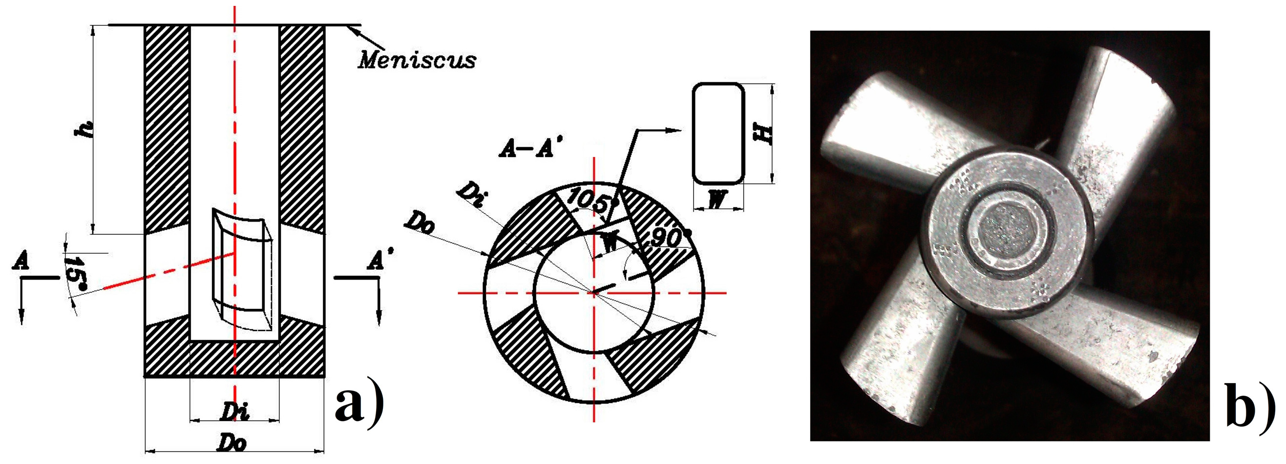
| Parameters | Inner Diameter (Di), m | External Diameter (Do), m | Outlet Height (H), m | Outlet Width (W), m | Outlet Angle, deg | Immersion Depth, m | |
|---|---|---|---|---|---|---|---|
| Nozzle Types | |||||||
| Swirling flow nozzle | 0.050 | 0.1 | 0.045 | 0.022 | 15 | 0.10 | |
| Bilateral-port nozzle | 0.050 | 0.1 | 0.050 | 0.040 | 15 | 0.10 | |
| Parameters | Value | Parameters | Value |
|---|---|---|---|
| Density of molten steel | 7200 kg·m−3 | Mold effective length | 0.7 m |
| Thermal conductivity of steel (solid phase) [24] | 26 W·m−1·K−1 | Model length | 1.4 m |
| Thermal conductivity of steel (liquid phase) [24] | 39 W·m−1·K−1 | Viscosity of molten steel | 0.0062 kg·m−1·s−1 |
| Liquidus temperature of molten steel | 1748 K | Latent heat of molten steel | 272 kJ·kg−1 |
| Solidus temperature of molten steel | 1658 K | Specific heat of molten steel | 725 J·kg−1·K−1 |
| Density of air | 1.225 kg·m−3 | Viscosity of air | 1.789 × 10⁻⁵ kg·m−1·s−1 |
| Thermal conductivity of air | 0.0242 W·m−1·K−1 | Specific heat of air | 1006 J·kg−1·K−1 |
| Relative permeability of steel, air, and copper mold [13] | 1 | Iron core relative permeability [13] | 1000 |
| Molten steel conductivity [13] | 7.14 × 10⁵ S·m−1 | Copper mold conductivities (T = 298 K [25] and 423 K [25]) | 4.7 × 10⁷ and 3.18 × 10⁷ S·m−1 |
| Inlet velocity | 0.716 m/s | Inlet temperature | 1781 K |
| Outlet velocity | 0.01033 m/s (0.62 m/min) | Heat flux density of mold wall [26] |
| Parameters | Value | Parameters | Value |
|---|---|---|---|
| Sectional dimension | 320 × 425 mm2 | Strand adopted swirling flow nozzle | I |
| Casting speed | 0.62 m/min | Strand adopted bilateral-port nozzle | II/III/IV/V |
| Steel grade | 65 Mn | Running current and frequency of F-EMS | 600/5 Hz |
| Running current and frequency of M-EMS | 500 A/2.5 Hz | Centre location of M-EMS | 0.465 m (below the meniscus) |
| Height of M-EMS | 0.40 m | Inner and external diameter of M-EMS | 0.836 m/1.236 m |
© 2018 by the authors. Licensee MDPI, Basel, Switzerland. This article is an open access article distributed under the terms and conditions of the Creative Commons Attribution (CC BY) license (http://creativecommons.org/licenses/by/4.0/).
Share and Cite
Sun, H.; Li, L.; Liu, C. Novel Opposite Stirring Mode in Bloom Continuous Casting Mould by Combining Swirling Flow Nozzle with EMS. Metals 2018, 8, 842. https://doi.org/10.3390/met8100842
Sun H, Li L, Liu C. Novel Opposite Stirring Mode in Bloom Continuous Casting Mould by Combining Swirling Flow Nozzle with EMS. Metals. 2018; 8(10):842. https://doi.org/10.3390/met8100842
Chicago/Turabian StyleSun, Haibo, Liejun Li, and Chengbin Liu. 2018. "Novel Opposite Stirring Mode in Bloom Continuous Casting Mould by Combining Swirling Flow Nozzle with EMS" Metals 8, no. 10: 842. https://doi.org/10.3390/met8100842