Finishing Turning of Ni Superalloy Haynes 282


Department of Mechanical Engineering, University Carlos III of Madrid, Avda. de la Universidad 30, Leganés, 28911 Madrid, Spain
*
Author to whom correspondence should be addressed.
Metals 2018, 8(10), 843; https://doi.org/10.3390/met8100843
Submission received: 8 October 2018
/
Revised: 14 October 2018
/
Accepted: 15 October 2018
/
Published: 18 October 2018
(This article belongs to the Special Issue Machining and Finishing of Nickel and Titanium Alloys)
Abstract
:Nickel-based superalloys are widely used in the aeronautical industry, especially in components requiring excellent corrosion resistance, enhanced thermal fatigue properties, and thermal stability. Haynes 282 is a nickel-based superalloy that was developed to improve the low weldability, formability, and creep strength of other γ’-strengthened Ni superalloys. Despite the industrial interest in Haynes 282, there is a lack of research that is focused on this alloy. Moreover, it is difficult to find studies dealing with the machinability of Haynes 282. Although Haynes 282 is considered an alloy with improved formability when compared with other nickel alloys, its machining performance should be analyzed. High pressure and temperature localized in the cutting zone, the abrasion generated by the hard carbides included in the material, and the tendency toward adhesion during machining are phenomena that generate extreme thermomechanical loading on the tool during the cutting process. Excessive wear results in reduced tool life, leading to frequent tool change, low productivity, and a high consumption of energy; consequentially, there are increased costs. With regard to tool materials, cemented carbide tools are widely used in different applications, and carbide is a recommended cutting material for turning Haynes 282, for both finishing and roughing operations. This work focuses on the finishing turning of Haynes 282 using coated carbide tools with conventional coolant. Machining forces, surface roughness, tool wear, and tool life were quantified for different cutting speeds and feeds.
1. Introduction
The continuous evolution of aviation engines requires the development of advanced materials and the improvement of manufacturing processes [1,2]. Nickel-based superalloys are widely used in aeroengine components, making up to about 50 wt % of the materials that are used for this application [3,4] due to their excellent mechanical properties at high temperatures and their resistance to corrosion [5]. Other applications are pressure valves, ocean and pollution control, food processing equipment, and nuclear reactors [6,7]. The Ni superalloy Haynes 282 has been recently developed with the aim of improving the weldability and fabricability of other wrought alloys with similar creep strengths [8]. Haynes 282 is a ’-strengthened Ni-based superalloy exhibiting excellent creep behavior, thermal stability, formability, and strain-age cracking improvement [9]. In comparison to other nickel-based superalloys, Haynes 282 has a unique combination of creep strength (a stress of 221 MPa is needed to produce 1% creep over 100 h at 816 °C) and thermal stability (Ultimate Tensile Strength of 975 MPa after 1000 h at 871 °C) [10], with a significantly lower cost than materials used in similar applications, such as Waspaloy.
Despite the industrial interest in Haynes 282, there is a lack of research focused on the machining processes of this alloy. In general, Haynes 282 is considered an alloy that presents with improved formability compared with other nickel alloys; however, machinability is not directly related to the performance of this parameter, and should be analyzed [11].
Machining of the most commonly used nickel-based superalloys (mainly Inconel 718 and Waspaloy) has been widely analyzed in the literature. Both alloys present challenges during machining due to their low thermal conductivity, hardness, strong work hardening, chemical affinity toward the tool material, and the presence of abrasive carbide particles. These phenomena induce extreme thermomechanical loads at the chip–tool interface, resulting in rapid tool wear [12,13]. Tool wear strongly influences the surface integrity of the workpiece [14,15], leading to the generation of residual stresses [16] and increments in roughness [17,18]. Tool wear mechanisms are generally related to friction at the contact interface between the tool, the chip, and the machined surface. The abrasive particles contained in nickel alloys, together with the low thermal conductivity and work hardening, cause elevated temperatures of up to 1200 °C [19,20], promoting wear by oxidation, diffusion, and abrasion. Furthermore, during the machining of nickel-based superalloys, welding and adhesion of the material to the tool occurs, causing damage on the tool rake face [1,15]. Flank wear, chipping, and catastrophic failures are induced by adhesion and abrasion at the clearance surface [21,22].
Tool selection is an important decision when machining nickel-based alloys. Good wear resistance, high strength and toughness, elevated hardness and toughness, and chemical stability at elevated temperatures are required for the machining of these difficult-to-cut materials [23]. Ceramic and carbide tools are mainly recommended for the turning operations of Ni alloys [3,13] (ceramic tools for roughing and semi-finishing turning, and coated carbide tools for finishing turning).
Ceramic tools have low mechanical and thermal shock resistance [24,25], low thermal conductivity, a high thermal expansion coefficient, and low toughness [26]. Moreover, with the addition of whisker reinforcement, they can be used at higher speeds than coated carbide tools [27].
Recently, polycrystalline cubic boron nitride (PCBN) tools with low CBN content were developed and implemented for finishing turning to overcome the stability problems that arise with diamond tools when cutting Nickel alloys. CBN is the second hardest material after diamond and, compared to ceramics, it has better hardness and resistance to fracture, but poorer chemical resistance [13]. These tools are suitable for a higher cutting speed than that which is reached with coated carbide tools; however, the increased cost and lower tenacity when compared to carbides are the main drawbacks of PCBN [28,29].
Carbide tools coated with PVD (Physical Vapor Deposition)-TiAlN, AlTiN, or AlCrTiN seem to be competitive with ceramic and CBN tools for the machining of the most widely used nickel-based superalloys (Inconel 718 and Waspaloy) due to their lower costs [1,30]. TiAlN coating reduces the cutting forces and improves the flank wear resistance in comparison with tools coated with TiN [31]. Chemical inertness, resistance to adhesive welding, a hardness of about 1500 HV at operating temperatures above 1000 °C, high oxidation resistance, and good wear resistance and strength are characteristics of TiAlNi leading to proper performance during the machining of Ni alloys [32,33].
Coated carbide tools are recommended for both finishing and roughing operations [11]. However, they cannot be used at high cutting speeds during the machining of nickel-based superalloys due to their thermochemical instability [13], and their recommended cutting speeds range between 30–70 m/min [11,34]. There is a lack of research focused on the turning of Haynes 282 compared to that focused on the turning of other nickel-based superalloys.
The aim of this work is to develop a parametric study focused on the finishing turning of Haynes 282 using coated carbide tools (multilayer coating of TiAl/TiAlN, which is recommended for machining Ni alloys) to analyze the tool performance under different cutting parameters.
2. Experimental Setup
2.1. Workpiece Material and Cutting Tools
The workpiece was a round bar (90 mm diameter) of Haynes 282 alloy manufactured following the AMS5951 specification, annealed at 1135 °C (the typical range is 1121–1149 °C), and age-hardened (1283 °C/2 h/Air cool + 1061 °C/8 h/Air cool). The material hardness was measured at several points, obtaining values ranging from 42.2 HRc to 43.5 HRc. The chemical composition of the Haynes 282 specimen used in this study is detailed in Table 1.
Coated micrograin carbide tools (CW) provided by SECO were used; these are especially recommended for the finishing turning of nickel-based superalloys. The carbide substrate was covered with a multilayer coating (TiAl/TiAlN). The insert presented a tip angle equal to 80°, a tip radius equal to 0.4 mm, a rake angle of 16°, a relief angle of 7°, and a honing radius of 25 µm. The tool holder allowed for the inner disposal of coolant (type SCLCR 2525M09JET from SECO).
2.2. Instrumentation and Setup
Turning tests were carried out in a lathe (Pinacho Smart turn 6/165) equipped with a dynamometer Kistler 9257B (Figure 1) for the cutting force measurements.
At the end of each pass, a rounded zone is generated due to the effect of the tool tip radius. This zone causes a sudden increment of the undeformed chip cross-section at the end of subsequent passes [35]. Since the cutting depth is small in the finishing operation, significant increments in cutting forces occur at the end of the pass, affecting tool wear. Therefore, to avoid this chip cross-section increment, a second tool was put into place in order to remove this transition zone once the force measurement is completed with the tested tool (see Figure 1).
Tool wear progression and workpiece roughness were periodically evaluated during test execution and repeated for each tested condition in order to check test repeatability. The tool wear level was measured through optical images obtained with a stereo microscope (Optika SZR) and using scanning electron microscopy (SEM) (Philips XL-30 with an EDSDX4i system). Otherwise, surface quality was quantified in terms of roughness measurement using a rugosimeter (Mitutoyo Series 178, model SJ-201). Representative roughness values were obtained as the mean of nine measurements of this parameter.
Cutting tests were carried out with coolant based on the water-soluble emulsion Rhenus FU50T with a mixing ratio of 6% at 7.5 bar.
Tool manufacturers do not include specific recommendations for selecting the cutting parameters for the machining of Haynes 282 because of the lack of industrial know-how in the machining of this alloy. General recommendations are available in the bibliography [11] and established ranges of the cutting speed (30–35 m/min) and feed rate (0.1–0.18 mm), and the maximum depth of cut (1 mm). However, based on the specific recommendations for the selected tool for finishing operations when used with other nickel-based alloys, such as Inconel 718, and based on preliminary test results, it was decided to increase the cutting speed and reduce the depth of cut. The cutting conditions used for the tests are presented in Table 2.
3. Results and Discussion
3.1. Cutting Forces
The evolution of the three components of the force was recorded during each test: cutting force (Fc), feed force (Ff), and back force (Fp). Two tests were carried out for each condition and variations lower than 5% were obtained; hence, the mean values were chosen to perform further analyses. The specific force components (kc, kf, and kp) were obtained as the ratio between each component and the cross-section of the chip. The value of a specific cutting force is related to wear mechanisms, such as brittle breaks at the cutting edge or adhesion.
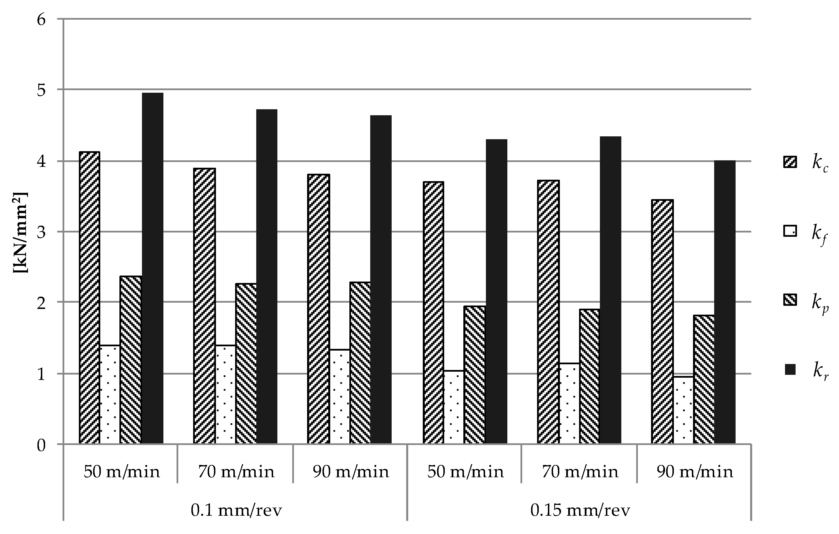
3.1.1. Specific Cutting Force Obtained with Fresh Tools
The values of the specific cutting forces that were measured at the beginning of the tests with fresh tools are summarized in Figure 2. For the cases that were analyzed, the values of the specific cutting force (kc) ranged from 3400 N/mm2 (case: Vc = 90 m/min and feed = 0.15 mm/rev) to 4120 N/mm2 (case: Vc = 50 m/min and feed = 0.1 mm/rev).
Effect of the cutting speed on the specific cutting forces:
- All of the components of the specific cutting force decreased with the cutting speed due to the thermal softening of the workpiece material. For feeds of 0.1 mm/rev and 0.15 mm/rev, decrements of 8% and 7% were found for the specific cutting force (kc), respectively, when the cutting speed increased from 50 m/min to 90 m/min. This effect was diminished in the rest of the specific cutting force components.
The effect of the feed on the specific cutting forces:
- A higher impact of the feed on the specific cutting force components was found, with recorded decrements of up to 10% for the specific cutting force (kc), up to 28% for the specific feed force (kf), and up to 20% for the specific back force (kp) when the feed was incremented from 0.1 mm/rev to 0.15 mm/rev. Large deformations and stresses were located at the cutting edge of the tool; hence, the larger the feed, the smaller the zone at the undeformed cross-section of the chip subjected to large levels of stress and deformation. Hence, the values of the specific cutting force components were lower at higher values of feed.
3.1.2. Evolution of the Specific Cutting Forces During the Tests
Figure 3 presents the evolution of the specific force components with cutting time. In all of the tested conditions, kc showed linear growth during the tool life. The kf and kp components presented different trends depending on the cutting speed, although in all of the cases, they increased more significantly than the kc component.
Effect of the cutting speed on the specific cutting forces:
- Cutting speed of 50 m/min: Two regions were identified. In the first region, moderate linear growth in the forces was registered. In the second region, a drastic increment in the kp component, which was not so evident in the case of the kf component, was recorded. These two regions could be related to the main wear mechanisms that were identified during the tests. The first region of the curve could be associated with the progressive erosion of the flank of the tool, combined with moderate chipping, while the second region could be associated with more aggressive chipping at the cutting edge, affecting the cutting edge integrity, and hence, the specific force components kf and kp. As the cutting speed increased, the tool wear resulting in enhanced specific forces increased.
- Cutting speed of 70 m/min: The behavior of the specific cutting force evolution was similar to the case with the lowest velocity. Two regions were observed in the evolution of kp and, to a lesser extent, in kf. In the first region, the three components of the cutting speed grew moderately, corresponding with the progression of flank wear (with chipping being moderate). In the second region, the kf and kp components grew significantly faster than in the previous region: this behavior is explained by the rapid deterioration of the cutting edge of the tool due to chipping.
- Cutting speed of 90 m/min: It is not possible to distinguish different growth trends. Throughout the test, the growth of the specific cutting force components was approximately linear. This tendency can be explained by the early onset of chipping wear, which was very severe since the first stages of the test.
Effect of the feed on the specific cutting forces:
- In general, the effect of the feed on the evolution of specific cutting force components during the tests was not significant.
The specific back force at the end of tool life reached values of up to 10 times the value obtained with a fresh tool, while the specific cutting and feed forces reached values of up to 2.5 and seven times those using a fresh tool, respectively. So, the evolution of the component kp could be used as a good indicator of the wear level of the tool, especially for low values of cutting speed.
3.2. Tool Wear and Tool Life
The tool wear level was monitored periodically during each test. The main wear modes identified during the experiments were: flank, chipping, built-up edge (BUE), and notch wear. At the beginning of all of the tested cutting parameters, the onset of all of the wear modes was observed. The criteria that was defined to declare the end of tool life were cutting edge breakage, or flank or notch wear larger than 0.4 mm.
Regardless of the cutting conditions, material adhesion was observed on all of the surfaces of the tool, along with the formation of BUE. However, this phenomenon was not dominant in terms of the cutting-edge life (see Figure 4 with the relief and rake surface views for different cutting conditions).
During the first instants of the performed tests, a greater deterioration of the cutting edge was observed at the depth of the cutline, affecting the rake and relief surfaces (notch wear). For longer cutting times, cutting edge breakages were generally along the whole cutting edge in contact with the chip, and were not noticeable as localized notch wear.
In all of the cases, the end of tool life was reached due to the catastrophic failure of the cutting edge, which was mainly due to fragile breakage coalescence leading to chipping. Both the increase in cutting speed and, with a reduced influence, the increase in feed accelerated the evolution of this wear mode, resulting in diminished tool life (see Table 3). Increased feed induces more elevated forces and unstable cutting, favoring the appearance of brittle breakages at the cutting edge. The increment of cutting speed results in enhanced temperature at the cutting zone [20], promoting the adhesion of the workpiece material to the tool and instabilities during cutting, leading to chipping.
Moreover, the high resistance to high temperature of Haynes 282 superalloy explains why the increase in the cutting speed reduced the strength of the tool material more than it did the workpiece material, causing a greater propensity to the fragile breakages of the cutting edge.
Flank wear linearly increased with cutting time. The increase of the flank was more pronounced for higher cutting speeds and, with reduced influence, also with feed enhancement. Flank wear extension at the end of tool life was diminished with the cutting speed and the feed (see Figure 4), because the tests were stopped at lower cutting times, since a dominant wear mechanism (chipping) induces tool failure.
Tool life was quantified in terms of the cutting time, the machined surface per time (Smach.t), and the machined surface per cutting edge (Sedge); see Equations (1) and (2), respectively, and Table 3, which summarizes the values obtained for all of the cases.
where Smach.t: machined surface per unit time (mm2/s); Sedge: machined surface per edge (mm2); Vc: cutting speed (m/min); f: feed (mm/rev); T: tool life (min).
Smach.t = Vc·f·1000/60
Sedge = Smach.t·T·60
For the maximum cutting speed (90 m/min), the chipping wear appeared at the first stages of the tests, with rapid evolution until the end of tool life (See Figure 4e–h). This evolution of the wear was faster for higher feeds, obtaining tool lives of 4.4 min for a feed of 0.15 mm/rev, and nine min for a feed of 0.1 m/rev.
For a cutting speed of 70 m/min, chipping wear appeared later (cutting times of 6.8 min for a feed of 0.1 mm/rev and 6.5 min for a feed of 0.15 mm/rev). Chipping accelerated later, leading to the end of tool life due to catastrophic breakage of the cutting edge (tool lives of 17 min and 14.6 min were obtained for the feeds 0.1 mm/rev and 0.15 mm/rev, respectively).
In the tests with a cutting speed of 50 m/min, the best tool duration was obtained (33.4 min and 29.2 min for 0.1 mm/rev and 0.15 mm/rev feeds, respectively), reaching the highest level of flank extension of 0.35 mm, which is close to the established end of tool life criterion (see Figure 4a–d). Even in this case, chipping inducing cutting-edge breakage was dominant, and caused the end of tool life.
The tool life for the range of cutting parameters considered in this work ranged from 3.9 min to 33.4 min. The maximum tool life in terms of the cutting time was found for the lowest cutting speed and feed rate. As discussed previously, the increase in cutting speed led to a rapid evolution of chipping wear on the cutting edge, resulting in diminished tool life.
Increasing the cutting speed from 50 m/min to 70 m/min and 90 m/min led to a tool life reduction of about 73% and 83%, respectively.
On the other hand, the machined surface per cutting edge is a good indicator of the industrial performance of a tool. For the lowest cutting speed (50 m/min) and with a feed of 0.15 mm/rev, the machined surface per cutting edge increased by up to 5% with respect to the lowest feed. Increasing the cutting speed to 70 m/min or 90 m/min did not lead to a larger machined surface per cutting edge due to the strongly reduced tool life. However, a good balance between tool life, maximum machined surface per cutting edge, and machined surface per unit time may lead to moderate production costs, and this can be achieved for a cutting speed equal to 70 m/min and a feed of 0.15 mm/rev.
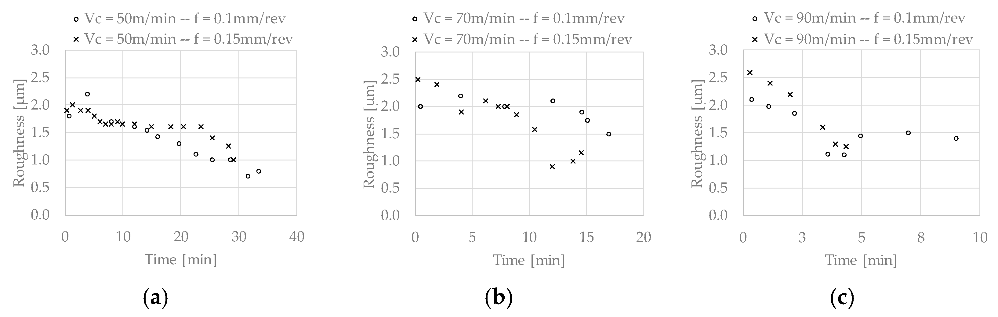
3.3. Surface Quality
Surface quality was checked in terms of the arithmetic average roughness (Ra) obtained at different stages of the tests. Three measurements at three different zones were recorded, obtaining moderate variations lower than 5%. The highest Ra value of the three measurements that were obtained for each condition was considered as the more conservative value of the roughness. It is represented in Figure 5.
At the beginning of the tests (fresh tool without significant wear), values of Ra between 1.8–2.6 µm were obtained. In general, as the tool wear evolved, lower values of Ra (between 0.7–1.5 µm) were obtained. The progression of tool wear resulted in an increased effective tool tip radius that was related to the decrease in Ra values. Similarly, the authors have observed this phenomenon in processes of finishing turning of Inconel 718 [36].
The best surface finishes were obtained in the tests with the lowest cutting speed (50 m/min). In these cutting conditions, chipping was not severe at the beginning, and thus, the evolution of the roughness was more linear.
In cases in which chipping severely affected the tool geometry from the first instants (cutting speeds of 70 m/min and 90 m/min), the evolution of the roughness was more erratic.
The feed did not significantly affect the surface roughness obtained.
4. Conclusions
This paper focuses on the finishing turning of Haynes 282, and is one of the first works dealing with the machinability of this alloy. Coated carbide tools (multilayer coating TiAl/TiAlN, which is recommended for machining Ni alloys) with conventional coolant were analyzed within certain ranges of cutting parameters recommended for Ni alloy machining.
The main conclusions of this work are summarized below:
- The specific back force at the end of tool life reached values that were up to 10 times greater than the values that were obtained when the tool was fresh. The specific cutting and feed force reached values of up to 2.5 and seven times those of the fresh tool, respectively. Thus, the evolution of the component kp could be used as a good indicator of the wear state of the tool in this machining process, especially for low values of cutting speed because, in these conditions, there is a drastic increase in kp in the last stages, prior to the cutting-edge failure.
- The main wear modes identified during the experiments were: flank, chipping, built-up edge (BUE), and notch wear. In all of the cutting conditions, the end of tool life was reached due to the catastrophic failure of the cutting edge, which was mainly due to the coalescence of fragile breakages of the tool (chipping).
- The tool life was very sensitive to cutting speed. In the tests with cutting speeds of 50 m/min and 70 m/min and feeds of 0.1 mm/rev and 0.15 mm/rev, cutting edge durations between 15–33 min were obtained, demonstrating the industrial application of these machining conditions.
- The increase in the feed moderately reduced the duration of the tool while increasing the machined surface per cutting edge and machined surface per unit of time, which is a good option for obtaining greater productivities in industrial applications.
- For all of the tested conditions, when the tools were without significant wear, values of Ra between 1.8–2.6 µm were obtained. Wear progression led to lower values of Ra (between 0.7–1.5 µm) because of the increased effective tool tip radius, which is related to the decrease of Ra values. The best surface quality in terms of the obtained roughness was obtained with the lowest value of cutting speed (50 m/min), while the feed had a negligible effect on this variable.
Author Contributions
Conceptualization, J.D.-Á. and J.L.C.; Data curation, J.D.-Á. and A.D.-Á.; Formal analysis, J.D.-Á., A.D.-Á. and J.L.C.; Funding acquisition, H.M. and J.L.C.; Investigation, J.D.-Á. and A.D.-Á.; Project administration, H.M. and J.L.C.; Resources, J.L.C.; Supervision, H.M. and J.L.C.; J.D.-Á, A.D.-Á., H.M. and J.L.C.; Visualization, A.D.-Á.; Writing—original draft, J.D.-Á and A.D.-Á.; Writing—review & editing, J.D.-Á., H.M. and J.L.C.
Funding
This research was funded by the Ministry of Economy, Industry and Competitiveness and the FEDER program, grant number DPI2014-56137-C2-2-R.
Conflicts of Interest
The authors declare no conflict of interest.
Abbreviations
| ae = radial depth |
| ap = axial depth |
| CBN: cubic boron nitride |
| d: depth of pass |
| f: feed rate |
| Fc: Cutting force |
| Ff: Feed force |
| Fp: Back force |
| Fr: Resultant force |
| kc: Specific cutting force |
| kf: Specific feed force |
| kp: Specific back force |
| kr: Specific resultant force |
| PCBN: Polycrystalline cubic boron nitride |
| SEM: Scanning electron microscopy |
| Smach.t: Machined surface per unit time |
| Sedge: Machined surface per cutting edge |
| T: Tool life |
| Vc: Cutting speed |
| Ra: Arithmetic Average Roughness |
References
- Zhu, D.; Zhang, X.; Ding, H. Tool wear characteristics in machining of nickel-based superalloys. Int. J. Mach. Tools Manuf. 2013, 64, 60–77. [Google Scholar] [CrossRef]
- Calleja, A.; Fernández, A.; Campa, F.J.; Lamikiz, A.; López De Lacalle, L.N. Reliable manufacturing process in turbine blisks and compressors. Procedia Eng. 2013, 63, 60–66. [Google Scholar] [CrossRef]
- Ezugwu, E.O.; Bonney, J.; Yamane, Y. An overview of the machinability of aeroengine alloys. J. Mater. Process. Technol. 2003, 134, 233–253. [Google Scholar] [CrossRef]
- González, H.; Calleja, A.; Pereira, O.; Ortega, N.; López de Lacalle, L.; Barton, M. Super Abrasive Machining of Integral Rotary Components Using Grinding Flank Tools. Metals 2018, 8, 24. [Google Scholar] [CrossRef]
- Cantero, J.L.; Díaz-Álvarez, J.; Miguélez, M.H.; Marín, N.C. Analysis of tool wear patterns in finishing turning of Inconel 718. Wear 2013, 297, 885–894. [Google Scholar] [CrossRef] [Green Version]
- Wang, F.; Cheng, X.; Liu, Y.; Yang, X.; Meng, F. Micromilling Simulation for the Hard-to-cut Material. Procedia Eng. 2017, 174, 693–699. [Google Scholar] [CrossRef]
- Thakur, A.; Gangopadhyay, S. State-of-the-art in surface integrity in machining of nickel-based super alloys. Int. J. Mach. Tools Manuf. 2016, 100, 25–54. [Google Scholar] [CrossRef]
- Kruger, K.L. HAYNES 282 alloy. In Materials for Ultra-Supercritical and Advanced Ultra-Supercritical Power Plants; Elsevier Ltd.: Amsterdam, The Netherlands, 2016; pp. 511–545. ISBN 9780081005583. [Google Scholar]
- Rodríguez-Millán, M.; Díaz-Álvarez, J.; Bernier, R.; Cantero, J.; Rusinek, A.; Miguelez, M. Thermo-Viscoplastic Behavior of Ni-Based Superalloy Haynes 282 and Its Application to Machining Simulation. Metals 2017, 7, 561. [Google Scholar] [CrossRef]
- Hood, R.; Soo, S.L.; Aspinwall, D.K.; Andrews, P.; Sage, C. Radius end milling of Haynes 282 nickel based superalloy. Proc. Inst. Mech. Eng. Part B J. Eng. Manuf. 2012, 226, 1745–1753. [Google Scholar] [CrossRef]
- Haynes International. Available online: https://haynesintl.com/alloys/alloy-portfolio_/High-temperature-Alloys/HAYNES282alloy.aspx (accessed on 17 october 2018).
- Ezugwu, E.O. Key improvements in the machining of difficult-to-cut aerospace superalloys. Int. J. Mach. Tools Manuf. 2005, 45, 1353–1367. [Google Scholar] [CrossRef]
- Choudhury, I.A.; El-Baradie, M.A. Machinability of nickel-base super alloys: A general review. J. Mater. Process. Technol. 1998, 77, 278–284. [Google Scholar] [CrossRef]
- Muñoz-Sánchez, A.; Canteli, J.A.; Cantero, J.L.; Miguelez, M.H. Numerical analysis of the tool wear effect in the machining induced residual stresses. Simul. Model. Pract. Theory 2011, 19, 872–886. [Google Scholar] [CrossRef] [Green Version]
- Xue, C.; Chen, W. Adhering layer formation and its effect on the wear of coated carbide tools during turning of a nickel-based alloy. Wear 2011, 270, 895–902. [Google Scholar] [CrossRef]
- Kartheek, G.; Srinivas, K.; Devaraj, C. Optimization of Residual Stresses in Hard Turning of Super Alloy Inconel 718. Mater. Today Proc. 2018, 5, 4592–4600. [Google Scholar] [CrossRef]
- Fernández-Valdivielso, A.; López de Lacalle, L.N.; Urbikain, G.; Rodriguez, A. Detecting the key geometrical features and grades of carbide inserts for the turning of nickel-based alloys concerning surface integrity. Proc. Inst. Mech. Eng. Part C J. Mech. Eng. Sci. 2016, 230, 3725–3742. [Google Scholar] [CrossRef]
- Urbikain, G.; de Lacalle, L.N.L. Modelling of surface roughness in inclined milling operations with circle-segment end mills. Simul. Model. Pract. Theory 2018, 84, 161–176. [Google Scholar] [CrossRef]
- Kitagawa, T.; Kubo, A.; Maekawa, K. Temperature and wear of cutting tools in high-speed machining of Inconel 718 and Ti 6Al 6V 2Sn. Wear 1997, 202, 142–148. [Google Scholar] [CrossRef]
- Díaz-Álvarez, J.; Tapetado, A.; Vázquez, C.; Miguélez, H. Temperature measurement and numerical prediction in machining inconel 718. Sensors 2017, 17, 1531. [Google Scholar] [CrossRef] [PubMed]
- Devillez, A.; Schneider, F.; Dominiak, S.; Dudzinski, D.; Larrouquere, D. Cutting forces and wear in dry machining of Inconel 718 with coated carbide tools. Wear 2007, 262, 931–942. [Google Scholar] [CrossRef]
- Hoier, P.; Malakizadi, A.; Stuppa, P.; Cedergren, S.; Klement, U. Microstructural characteristics of Alloy 718 and Waspaloy and their influence on flank wear during turning. Wear 2018, 400–401, 184–193. [Google Scholar] [CrossRef]
- Thellaputta, G.R.; Chandra, P.S.; Rao, C.S.P. Machinability of Nickel Based Superalloys: A Review. Mater. Today Proc. 2017, 4, 3712–3721. [Google Scholar] [CrossRef]
- Hu, H.J.; Huang, W.J. Tool life models of nano ceramic tool for turning hard steel based on FEM simulation and experiments. Ceram. Int. 2014, 40, 8987–8996. [Google Scholar] [CrossRef]
- Kumar, A.S.; Durai, A.R.; Sornakumar, T. Wear behaviour of alumina based ceramic cutting tools on machining steels. Tribol. Int. 2006, 39, 191–197. [Google Scholar] [CrossRef]
- Lima, F.F.; Sales, W.F.; Costa, E.S.; da Silva, F.J.; Machado, Á.R. Wear of ceramic tools when machining Inconel 751 using argon and oxygen as lubri-cooling atmospheres. Ceram. Int. 2017, 43, 677–685. [Google Scholar] [CrossRef]
- Altin, A.; Nalbant, M.; Taskesen, A. The effects of cutting speed on tool wear and tool life when machining Inconel 718 with ceramic tools. Mater. Des. 2007, 28, 2518–2522. [Google Scholar] [CrossRef]
- Calleja-Ochoa, A.; Gonzalez-Barrio, H.; Polvorosa-Teijeiro, R.; Ortega-Rodriguez, N.; Lopez-de-Lacalle-Marcaide, L.N. Multitasking machines: Evolution, resources, processes and scheduling. DYNA 2017, 92, 637–642. [Google Scholar]
- Lin, Z.C.; Chen, D.Y. A study of cutting with a CBN tool. J. Mater. Process. Technol. 1995, 49, 149–164. [Google Scholar] [CrossRef]
- Grzesik, W.; Niesłony, P.; Habrat, W.; Sieniawski, J.; Laskowski, P. Investigation of tool wear in the turning of Inconel 718 superalloy in terms of process performance and productivity enhancement. Tribol. Int. 2018, 118, 337–346. [Google Scholar] [CrossRef]
- Li, H.Y.; He, H.B.; Han, W.Q.; Yang, J.; Gu, T.; Li, Y.M.; Lyu, S.K. A study on cutting and tribology performances of TiN and TiAlN coated tools. Int. J. Precis. Eng. Manuf. 2015, 16, 781–786. [Google Scholar] [CrossRef]
- Thakur, D.G.; Ramamoorthy, B.; Vijayaraghavan, L. Study on the machinability characteristics of superalloy Inconel 718 during high speed turning. Mater. Des. 2009, 30, 1718–1725. [Google Scholar] [CrossRef]
- Bouzakis, K.D.; Michailidis, N.; Skordaris, G.; Bouzakis, E.; Biermann, D.; M’Saoubi, R. Cutting with coated tools: Coating technologies, characterization methods and performance optimization. CIRP Ann. Manuf. Technol. 2012, 61, 703–723. [Google Scholar] [CrossRef]
- Olovsjö, S.; Nyborg, L. Influence of microstructure on wear behaviour of uncoated WC tools in turning of Alloy 718 and Waspaloy. Wear 2012, 282–283, 12–21. [Google Scholar] [CrossRef]
- Cantero, J.; Díaz-Álvarez, J.; Infante-García, D.; Rodríguez, M.; Criado, V. High Speed Finish Turning of Inconel 718 Using PCBN Tools under Dry Conditions. Metals 2018, 8, 192. [Google Scholar] [CrossRef]
- Díaz-Álvarez, J.; Criado, V.; Miguélez, H.; Cantero, J. PCBN Performance in High Speed Finishing Turning of Inconel 718. Metals 2018, 8, 582. [Google Scholar] [CrossRef]
Figure 1.
Experimental setup.

Figure 2.
Initial specific cutting forces for the carbide tools.

Figure 3.
Evolution of the cutting forces for the carbide tool.
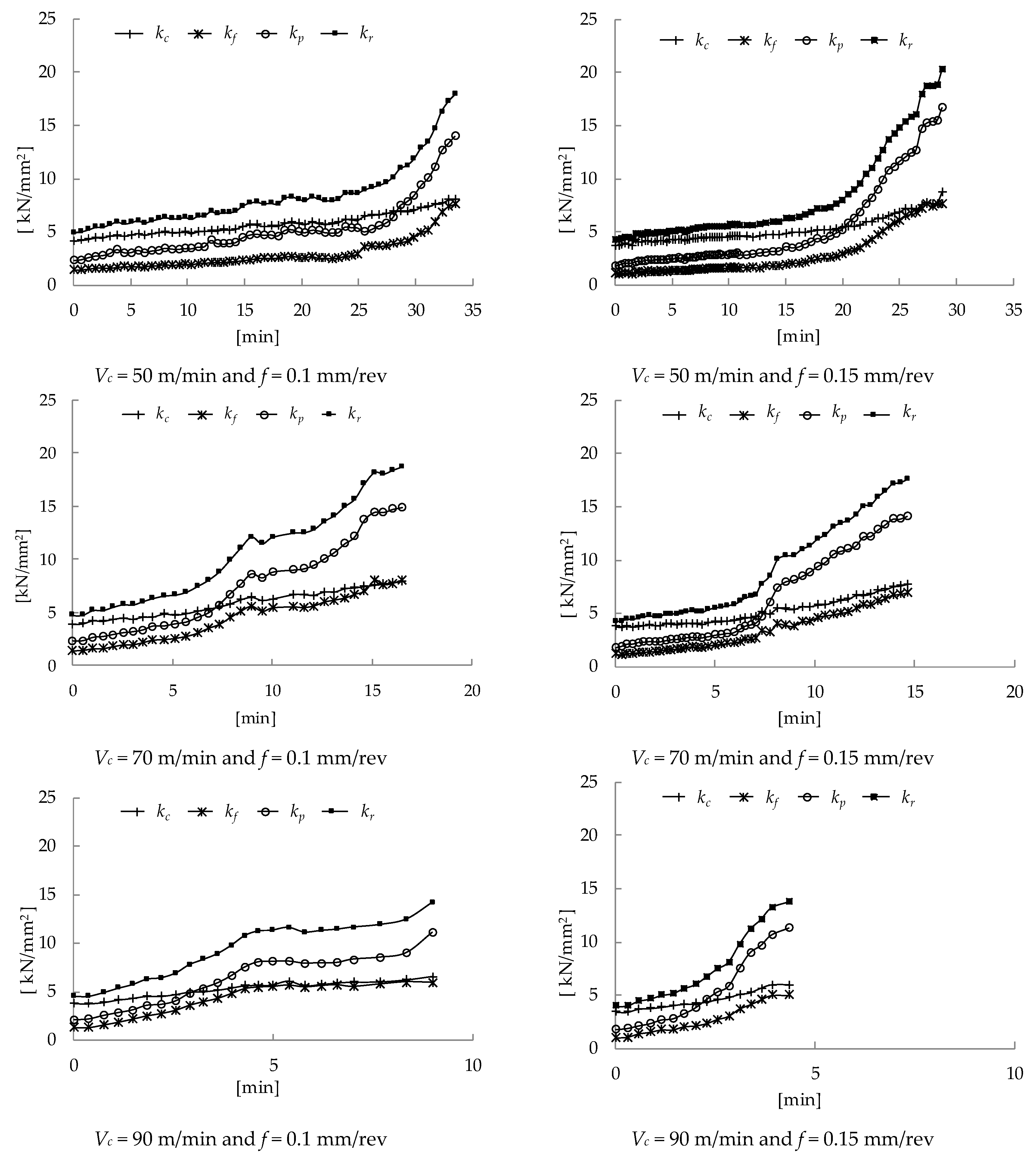
Figure 4.
SEM images of the tool, for different cutting parameters, at the end of the tool life. Cutting speed of 50 m/min and feed of 0.1 mm/rev: (a) relief surface view; (b) rake surface view. Cutting speed of 50 m/min and feed of 0.15 mm/rev: (c) relief surface view; (d) rake surface view. Cutting speed of 90 m/min and feed of 0.1 mm/rev: (e) relief surface view; (f) rake surface view. Cutting speed of 90 m/min and feed of 0.15 mm/rev: (g) relief surface view; (h) rake surface view.


Figure 5.
Machined surface roughness for all of the tested cutting parameters: (a) cutting speed = 50 m/min; (b) cutting speed = 70 m/min; (c) cutting speed = 90 m/min.
Figure 5.
Machined surface roughness for all of the tested cutting parameters: (a) cutting speed = 50 m/min; (b) cutting speed = 70 m/min; (c) cutting speed = 90 m/min.

Table 1.
Chemical composition of Haynes 282 alloy.
| Element (%) | Ni | Cr | Fe | Nb | Mo | Ti | Al | Co | Si | Cu | Mn | C |
|---|---|---|---|---|---|---|---|---|---|---|---|---|
| Haynes 282 | 57 | 19.42 | 0.87 | ˂0.01 | 8.52 | 2.22 | 1.41 | 10.2 | ˂0.05 | ˂0.01 | 0.06 | 0.062 |
Table 2.
Cutting conditions for tool wear tests.
| Cutting Speed (m/min) | Feed (mm/rev) | Pass Depth (mm) |
|---|---|---|
| 50 | 0.1 | 0.25 |
| 0.15 | ||
| 70 | 0.1 | |
| 0.15 | ||
| 90 | 0.1 | |
| 0.15 |
Table 3.
Tool life in terms of cutting time (min), Smach.t (machined surface per unit time (mm2/s)), and Sedge (machined surface per edge (mm2)).
Table 3.
Tool life in terms of cutting time (min), Smach.t (machined surface per unit time (mm2/s)), and Sedge (machined surface per edge (mm2)).
| Tool | Cutting Speed (m/min) | Feed (mm/rev) | Depth (mm) | Life (min) | Machined Surface per Unit Time (mm2/s) | Machined Surface per Cutting Edge (mm2) |
|---|---|---|---|---|---|---|
| Carbide (TS2000, Seco) | 50 | 0.1 | 0.25 | 33.4 | 83.3 | 167,139 |
| 0.15 | 29.2 | 125.0 | 218,916 | |||
| 70 | 0.1 | 0.25 | 17.0 | 117.0 | 118,681 | |
| 0.15 | 14.6 | 175.0 | 153,215 | |||
| 90 | 0.1 | 0.25 | 9.0 | 150.0 | 80,961 | |
| 0.15 | 4.4 | 225.0 | 58,826 |
© 2018 by the authors. Licensee MDPI, Basel, Switzerland. This article is an open access article distributed under the terms and conditions of the Creative Commons Attribution (CC BY) license (http://creativecommons.org/licenses/by/4.0/).
Share and Cite
MDPI and ACS Style
Díaz-Álvarez, J.; Díaz-Álvarez, A.; Miguélez, H.; Cantero, J.L. Finishing Turning of Ni Superalloy Haynes 282. Metals 2018, 8, 843. https://doi.org/10.3390/met8100843
AMA Style
Díaz-Álvarez J, Díaz-Álvarez A, Miguélez H, Cantero JL. Finishing Turning of Ni Superalloy Haynes 282. Metals. 2018; 8(10):843. https://doi.org/10.3390/met8100843
Chicago/Turabian StyleDíaz-Álvarez, José, Antonio Díaz-Álvarez, Henar Miguélez, and José Luis Cantero. 2018. "Finishing Turning of Ni Superalloy Haynes 282" Metals 8, no. 10: 843. https://doi.org/10.3390/met8100843
Note that from the first issue of 2016, this journal uses article numbers instead of page numbers. See further details here.