Hot Deformation Behavior and Constitutive Modeling of H13-Mod Steel

College of Materials and Metallurgy, Guizhou University, Gui Yang 550000, China
*
Author to whom correspondence should be addressed.
Metals 2018, 8(10), 846; https://doi.org/10.3390/met8100846
Submission received: 2 October 2018
/
Revised: 12 October 2018
/
Accepted: 15 October 2018
/
Published: 18 October 2018
Abstract
:The H13-mod steel optimized by composition and heat treatment has reached the performance index of the shield machine hob. The hot deformation behavior of the H13-mod steel was investigated by compression tests in the temperature range from 900 to 1150 °C and the strain rate range from 0.01 to 10 s−1. The true stress-strain curve showed that the rising stress at the beginning of deformation was mainly caused by work hardening. After the peak stress was attained, the curve drop and the flow softening phenomenon became more obvious at low strain rates. The flow behavior of the H13-mod steel was predicted by a strain-compensated Arrhenius-type constitutive equation. The relationship between the material constant in the Arrhenius-type constitutive equation and the true strain was established by a sixth-order polynomial. The correlation coefficient between the experimental value and the predicted value reached 0.987, which indicated that the constitutive equation can accurately estimate the flow stress during the deformation process. A good linear correlation was achieved between the peak stress (strain), critical stress (strain) and the Zener‒Hollomon parameters. The processing maps of the H13-mod steel under different strains were established. The instability region was mainly concentrated in the high-strain-rate region; however, the microstructure did not show any evidence of instability at high temperatures and high strain rates. Combined with the microstructure and electron backscattered diffraction (EBSD) test results under different deformations, the optimum hot working parameters were concluded to be 998–1026 °C and 0.01–0.02 s−1 and 1140–1150 °C and 0.01–0.057 s−1.
1. Introduction
Shield machines are widely used in major projects such as urban subways, railway and highway transportation, energy transportation, underground passages, etc. They have the advantages of high excavation speed, high construction quality, low labor intensity, high cost effectiveness, and environmental protection [1]. The harsh working environment of shield machines necessitates that the tool have high hardness, high wear resistance, good impact toughness, certain anti-tempering performance, and good processing performance. At present, the international hob materials are mainly based on American AISI 4340 steel and German X50CrMoV51 steel [2]. The former exhibits higher toughness [3], whereas the latter exhibits higher hardness [1]. Because the domestic R&D of hobs started relatively late, most hob materials remain in the development stage; these materials include 9Cr2Mo [4], 5Cr5MoSiV1 [5], and 5Cr5MoV [6], which generally have shortcomings such as a poor combination of strength and toughness and short service life. Many international hob materials have been developed from AISI H13, including the aforementioned X50CrMoV51 steel. However, H13 steel itself has a high content of alloying elements, which tend to segregate during solidification, adversely affecting product performance. Numerous scholars have improved the mechanical properties of H13 steel by optimizing the composition and heat-treatment conditions and applying surface treatments [7,8,9,10,11,12,13]. However, the H13 steel prepared by these processes does not demonstrate a good match between strength and toughness and cannot be used under complex geological conditions. Therefore, the development of a hob material with both strength and toughness is important.
An increase in the carbon content of steel is well known to increase its strength and decrease its plastic toughness. However, an excessively high carbon content causes an increase in the brittleness of the steel. Therefore, we strictly controlled the carbon content in the range from 0.48% to 0.52%, optimized the content of other major alloying elements, reduced the impurity content and controlled the shape and size of inclusions to improve the performance of steel. The modified H13 steel, hereafter referred to as H13-mod, was developed by optimizing the heat-treatment conditions. Its hardness reaches 57 HRC and its impact toughness is 15 J/cm2, which fully satisfies the performance requirements of the shield hob.
H13-mod exhibits excellent mechanical properties. However, whether it can be processed into a qualified part product is not only determined by the material’s characteristics but also by the processing technology. At the same time, the higher carbon content of H13-mod increases the difficulty of processing and its higher alloying element content makes the hot-working process difficult to control. These effects are also a key issue for the successful application of H13-mod to shield hobs. Microstructural changes such as dislocation generation, rearrangement, dynamic recovery (DRV), and dynamic recrystallization (DRX) during thermal processing are closely related to tool performance. The microstructure depends mainly on deformation parameters such as the strain rate, strain, and the deformation temperature. The material may exhibit poor workability under certain combinations of strain, temperature, and strain rate while demonstrating good workability under other conditions [14]. Some processing regions are not favorable for hot deformation because of the occurrence of instabilities such as localized deformation, adiabatic shear bands, hot brittleness, or wedge cracking, which leads to deterioration of the mechanical properties of the final product However, DRX or DRV can substantially improve the processing performance, which tends to enhance the mechanical properties of the deformed parts [15,16]. DRX also plays an important role in optimization of the microstructure. DRX can refine the microstructure of austenite [17,18,19] and prevent deformation defects prior to the transformation to martensite [20]. Generally speaking, the occurrence of DRX is also related to Stacking Fault Energy (SFE) in materials. It has been pointed out that metal with high SFE is prone to dynamic recovery during thermal deformation, resulting in the increase of energy required for DRX [21].
The flow stress curves obtained by thermal compression simulations can provide a theoretical basis for the thermal processing of the material. Constitutive equations associated with the deformation parameters can better describe the rheological properties of materials such as Al–Zn–Mg–Er–Zr alloy [22], fine-grained Inconel 718 superalloy [23], Cr–Ni–Mo alloyed steel [24], GCr15 steel [25] and X20Cr13 martensitic stainless steel [26]. The stress values calculated by the appropriate constitutive equations strongly agree with experimental results. As an effective method to optimize thermal processing and control the microstructure, processing maps have been developed for many materials, including austenitic stainless steel [27], martensitic steel [20], a fine-grained Inconel 718 superalloy [23], a magnesium alloy [28], and a titanium alloy [29]. The reasonable processing range of the material is determined by the safety region and the instability region in the processing diagram to avoid the aforementioned occurrence of instabilities. Establishing accurate constitutive equations and processing maps will help optimize the thermal processing and achieve a uniform microstructure by controlling the DRX.
In the present study, to investigate the hot deformation behavior of modified H13 steel, a hot compression experiment was carried out with a Gleeble 3800 thermomechanical simulator over the temperature range from 900 to 1150 °C and a strain-rate range from 0.01 to 10 s−1. The flow behavior of the H13-mod steel was predicted by a strain-compensated Arrhenius-type constitutive equation and the processing maps for hot working at different strains were constructed to optimize its processing parameters, providing theoretical guidance for the engineering application of H13-mod steel.
2. Experimental
The chemical composition of the H13-mod steel is shown in Table 1. Cylindrical compression specimens 12 mm × ø8 mm were machined from the bars. Hot compression testing was performed on a Gleeble 3800 (DSI, Troy, NY, USA) thermomechanical simulator. The sample was heated to 1150 °C at a heating rate of 10 °C/s for 300 s to obtain a uniform microstructure. The sample was then cooled to 900, 950, 1000, 1050, 1100, 1150 °C at a cooling rate of 5 °C/s. The sample was compressed at a strain rate of 0.01, 0.1, 10 s−1 to a true strain of 0.9. A graphite lubricant was coated on the top and bottom surfaces of the specimen and a tantalum foil with a thickness of 0.1 mm was placed between the cylindrical specimen and the tool to reduce friction and avoid adhesion. It was then rapidly quenched to room temperature to maintain its deformed microstructure. The hot compressed sample was cut along the compression axis. After mechanical polishing, the sample was etched using 4% nitric acid alcohol. The center area was observed by SOPTOP ICX41M optical microscopy (Ningbo Sunny Instruments Co., Ltd., Ningbo, Zhejiang, China). The sample for analysis by electron-backscatter diffraction (EBSD) was ground, mechanically polished, and then electropolished at a voltage of 20 V for 30 s in an electropolishing solution composed of 200 mL of ethanol and 10 mL of perchloric acid. EBSD observation was conducted on a Hitachi S-3400 N SEM equipped with an HKL-EBSD system (Oxford Instruments, Oxford, UK) The step size of the EBSD orientation mapping was 0.2 μm.
3. Results and Discussion
3.1. True Stress-Strain Curves
Figure 1 shows the true stress-true strain curve of the H13-mod steel at different strain rates. In the early stage of deformation, due to the work-hardening effect, the dislocation density increases continuously and the flow stress increases sharply with increasing strain. As the strain increases, the dislocation density and the dislocation rearrangement offset part of the increase in dislocation density due to work hardening and the flow stress slowly reaches a peak value. The peak stress gradually decreases as the strain rate decreases and the deformation temperature increases. The typical single peak of the curve illustrates that DRX is the primary softening mechanism [30]. During the subsequent deformation process, the flow stress gradually decreases and a substantial softening phenomenon occurs until the flow stress reaches a steady state. The steady-state stress reflects the strain hardening and strain softening caused by the formation of new grains and related grain-boundary migration [24]. Notably, the flow softening phenomenon is quite different in different deformation conditions. The occurrence of this phenomenon is related to deformation heating and microstructure changes such as DRV or DRX. To evaluate the flow softening behavior more intuitively, we use the extent of flow softening () according to the previous practice, where is the peak stress and is the flow stress at a strain of 0.6 [23]. The extent of flow softening under different deformation conditions is shown in Figure 2, which shows that at low strain rates, the extent of softening of the flow is greater because the low strain rate gives a sufficient incubation period for recrystallization; recrystallization promotes the softening process, and this phenomenon is more pronounced at high temperatures. As the strain rate increases, the extent of flow softening decreases. This phenomenon is attributed to higher work hardening speeds at high strain rates slowing the softening caused by DRX, thereby causing the curve to be stable [20]. This effect is also evident in the stress-strain curve. The curve in Figure 1a shows a dramatic drop after reaching the peak. In Figure 1d, especially at 1100 and 1150 °C, the stress shows only a slight decrease after the strain of 0.4 and the difference between the peak stress and the steady-state stress is small after the true strain of 0.8. At the same time, we observe that the flow stress tends to reach a steady state at high temperatures and low strain rates, which may be a consequence of higher temperatures and lower strain rates promoting the volume fraction of DRX [31]. These results are consistent with the results of flow softening.
Although the true stress-strain curve reflects the intrinsic relationship between flow stress and thermodynamics, we cannot elucidate the deformation mechanism of the material solely by the true stress-strain curve. For example, flow softening is often associated with microstructure mechanisms such as DRX, flow instability and cracking [16]. Therefore, we investigated the kinetics, processing maps and microstructures in detail, as discussed in the following subsections.
3.2. Kinetic Analysis
DRX begins when the strain reaches a critical value; thus, the critical strain strongly affects DRX. In recent years, numerous methods for determining the critical strain have been reported [21,32]. The most widely used method is to fit the true stress-strain curve and then derive the stress to obtain the work-hardening rate curve. The critical stress is obtained from the inflection point of the curve. Figure 3 is a graph showing the work-hardening rate of the material at 900 °C and at a strain rate of 0.01 s−1. From Figure 3, we can obtain the critical stress , saturation stress , stable stress , peak stress under this deformation condition. The values of the various parameters under different deformation conditions are shown in Table 2.
The relationship between the mechanical and thermodynamic parameters of the metal involved in different deformation processes can be expressed using the flow stress equation. The most important data in the high-temperature deformation process are the flow stress; the maximum influence on the flow stress is the strain rate and the deformation temperature T. The relationship between and T can be expressed by the Garofalo formula. Based on the Garofalo formula, Sellars and Tgart [33] proposed a new constitutive equation that includes the thermal activation energy Q and the deformation temperature T, which is the Arrhenius equation:
According to the stress level, this equation can be divided into the following three forms.
(1) When the stress is low (ασ < 0.8), it can be simplified into an exponential form:
(2) When the stress is high (ασ < 1.2), it can be simplified into a power exponential form:
(3) It can be simplified into a hyperbolic sinusoidal form over the entire stress range:
In these formulas, is the strain rate, A is the structural factor of the material, α is the stress-level parameter (α = β/n), n is the stress index, σ is the flow stress, and Q is the thermal deformation activation energy. Whether the metal material is easily deformed can be estimated from the magnitude of the Q value. R is the molar gas constant, i.e., R = 8.31441 J·mol−1·K−1, and T is the absolute temperature.
When Zener and Hollomon [34] studied the stress-strain relationship of steel, they found that the effect of deformation rate and temperature on flow stress can be expressed by the Z parameter:
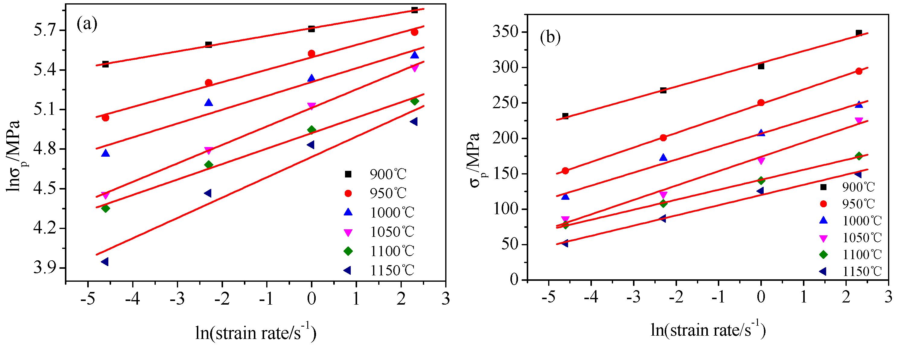
We linearly fitted the logarithm of Equations (2) and (3), where takes the peak stress as the calculation value. The relationship between − and − is shown in Figure 4a,b, respectively. Taking the average of the reciprocal of the slope as the values of n1 and β, we found that n1 = 9.894, β = 0.0594 and α = 0.0059 by calculation.
Furthermore, by taking the logarithm of the natural number for Equation (4), we find that has a linear relationship with and T−1, as shown in Figure 4c,d. By linear regression analysis, we obtain n = 7.06 and Q = 563.62 kJ·mol−1. At the same time, the relationship between lnZ and is fitted and the intercept is the value of lnA, where A = . The values of A, α, n and Q are calculated from the experimental data; thus, the flow stress equation of the material is
The relationship between peak stress and Z parameter is as follows:
Strain is generally assumed to have little effect on the thermal deformation behavior of metallic materials. However, a large number of studies have shown that the thermal deformation activation energy and the material constant are strongly affected by strain during the whole deformation process [23,35,36,37]; we observe this effect from the true stress-strain curve. Therefore, strain should be introduced into the Arrhenius equation to improve the accuracy of the flow stress prediction. For this reason, based on the experimental data, we calculated the values of Q, n, α and lnA of H13-mod steel at a strain of 0.05 to 0.9 with an interval of 0.05. Table 3 shows the values of Q, n, α and lnA for H13-mod steel at different strains. These results show that the effect of strain on Q, n, α and lnA is substantial. These deformation constants and strains were subjected to the polynomial fitting shown in Equation (8), and the order was 1 to 9 [38,39]. Based on the correlation analysis, a six-step fitting was performed. The fitting coefficients are listed in Table 4. From Figure 5, the experimental data and the polynomial fitting results show a good correlation.
After calculating the relationship between the material constant and strain, we can more accurately predict the stress value under a specific strain. According to Equation (3), the constitutive equation of the H13-mod steel under a specific strain can be written as
A comparison between the experimental flow stress and flow stress predicted by the Arrhenius-type constitutive equation is shown in Figure 6. Through Figure 6, we observe that the experimental value has a high degree of coincidence with the predicted value, indicating that the proposed constitutive equation has higher prediction accuracy. To further illustrate the accuracy of the constitutive equation, we used the standard statistical parameters to calculate the correlation coefficient (R) and the mean absolute relative error (∆) [40,41] according to the equations:
where is the experimental flow stress, is the predicted flow stress, and are the mean values of and , respectively. In addition, N is the total number of data employed in this work. The correlation coefficient (R) is commonly used to reflect the capability of the linear relationship between the experimental and predicted data. Figure 7 shows that a good correlation (R = 0.99) is obtained between the experimental and the predicted data. This correlation indicates that the proposed constitutive equations exhibit an excellent fit with the measured values. In the present work, the ∆ value is calculated to be approximately 6.3% for H13-mod steel deformed in the temperature range from 900 to 1150 °C and strain rate range from 0.01 to10 s−1, which reflects the good prediction capabilities of the proposed constitutive equation.
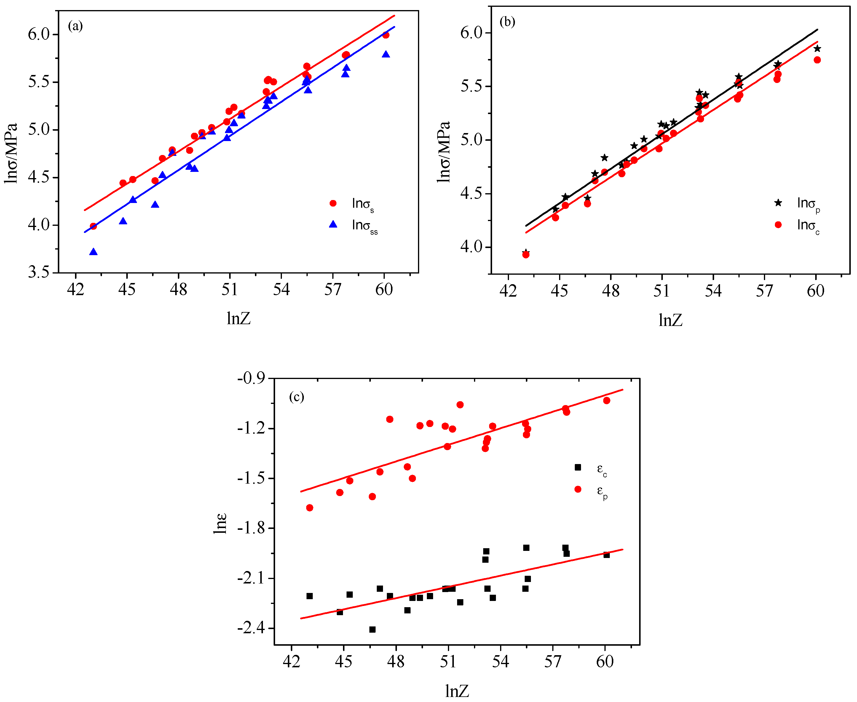
Jorge and Balancin [42] suggested that the mechanical parameters can be described by simple Zener parameters. Moreover, this method is being cited in an increasing number of literature works. The Z parameters and these mechanical performance parameters can be described by the following power exponential equation:
The Z parameters and the changes in these parameters are shown in Figure 8a,b. This figure shows that the mechanical performance parameters have a good linear relationship with the Z parameters. By linear regression, we obtain the slopes of the different curves:
At the same time, some studies have shown that there is a linear relationship between the critical strain and the peak strain , so we also plotted the relationship between and and Z parameters, as shown in Figure 8c. From the figure we can see that the two have a good linear relationship with the Z parameters:
3.3. Processing Map
Thus far, the most widely used model for metals in a thermal compression process is the dynamic material model (DMM) proposed by Prasad et al. [16,43,44]. The DMM links the large plastic deformation and the dissipation of the structure, possibly clarifying how the energy of the external action is dissipated through the plastic deformation of the workpiece. According to the principles of thermodynamics, the deformation process is regarded as a closed thermodynamic system. The entire deformation process is related to the dissipation of energy. According to the model, the total power of the input system is P, and the energy consumed by the thermal deformation and the energy consumed by the evolution of the internal organizational structure are the dissipation amount G and the dissipation coordination J, respectively. The relationship is
The strain-rate sensitivity coefficient m can be used to distribute the relationship between the dissipation amount G and the dissipation coefficient J during thermal deformation:
According to irreversible thermodynamics, the relationship between and can be approximately illustrated as
Combining Equations (14) and (15), we can rewrite m as
When the temperature and strain are constant, the stress and the strain rate of the specimen are constitutively related: or (K and K1 are constants). Therefore, the dissipation J can be defined as
For steady-state rheology of viscoplastic solids, m ranges from 0 to 1. Equation (14) shows that the larger the value of m, the larger G of the metal material, and that the smaller the value of m, the larger P of the metal material. When m = 1, the metal material is in a particularly ideal dissipative condition. At this time, the dissipation coefficient J reaches the maximum value .
Equation (18) shows that η and m, which is a function of the strain ε, the strain rate and the deformation temperature T, are closely related. The variation of η with T and constitutes a power dissipation diagram and different regions in the map correspond to different microstructures. The value of η can reflect the thermal processing properties of the metal material to a certain extent. However, the power dissipation efficiency value of the instability region is sometimes also particularly high; thus, when the η value is large, the hot workability of the material is not necessarily good. Therefore, it is necessary for us to find the processing instability region.
According to the principle of entropy proposed by Ziegler [45], Prasad et al. applied the extreme principle of irreversible thermodynamics to continuum mechanics of large plastic flow and obtained the inequality criterion of plastic rheological instability:
where is the strain rate and is a dimensionless instability parameter. The variation of with temperature and strain rate constitutes an instability map and the flow instabilities are predicted to occur when becomes negative. We obtain the processing map of the material by superimposing the power dissipation map on the instability map. From the processing map, we obtain the strain rate and temperature range suitable for processing the material or some flow instability regions such as adiabatic shear bands or flow localization [23].
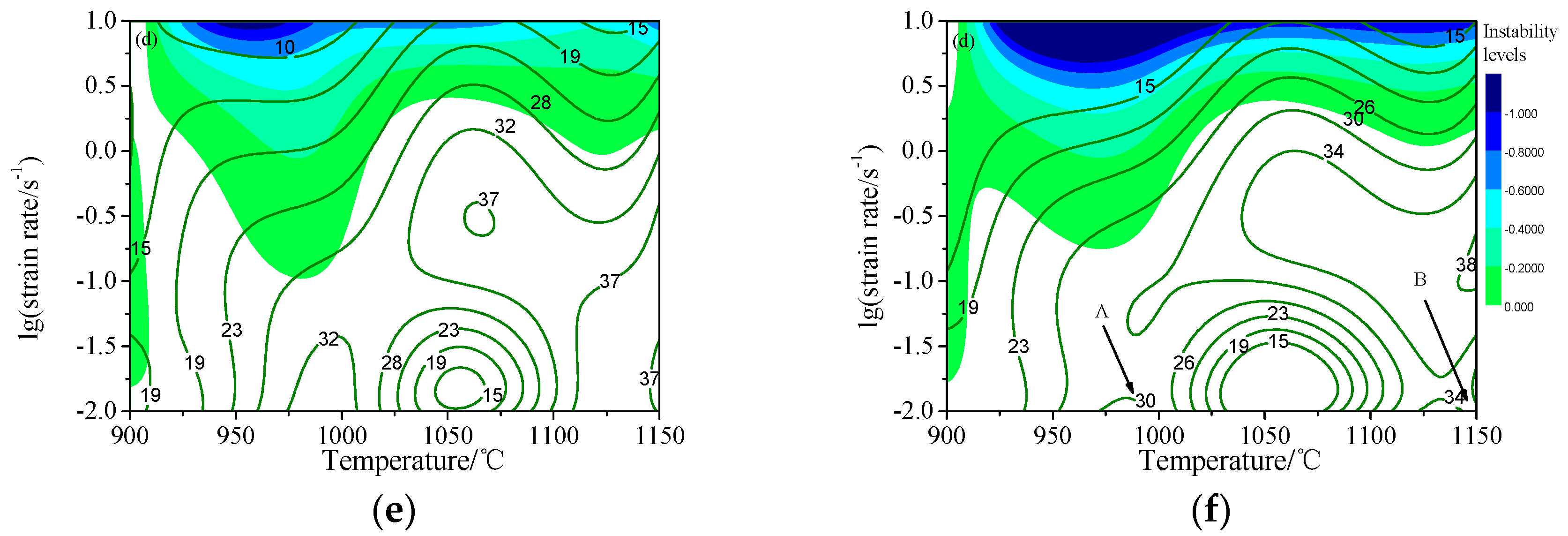
Based on the above theory, we have established processing maps with true strains of 0.4, 0.5, 0.6, 0.7, 0.8, and 0.9, as shown in Figure 9. In the processing maps, the efficiency is represented by a contour line, the instability region is represented by colored shading and the instability level of the instability region is represented by a different color. Processing maps have a guiding role in the design of thermal processing. For example, processing in unstable areas should be avoided during processing [46]. It can be seen from the processing map that η and the unstable region of the flow vary with the strain. When the true strain is 0.4, the processing map exhibits two instability regions that occur at temperature ranges from 910 to 1020 °C and from 1030 °C to 1150 °C and strain-rate ranges from 0.03 to 10 s−1 and from 0.41 to 10 s−1, respectively. In the processing stability region, two peaks of efficiency occur in this region: one is in the temperature range 998–1026 °C with a relatively high strain rate from 0.01 to 0.02 s−1 and the other is in the temperature range 1140–1150 °C with a strain rate from 0.01 to 0.057 s−1 (marked A and B in Figure 9a).
In general, a higher value of η indicates that the microstructure involved in the deformation process consumes more energy, as is the case for DRV, DRX or a phase transition, and high η contributes to thermal processing [47]. DRX has been reported occur when the value of η is between 0.3 and 0.5 [48,49]. However, the values of the A and B regions in the present study are just within this range, indicating that DRX occurred under the deformation conditions; we also observe this phenomenon from the stress-strain curve. With increasing strain, the instability region gradually moves to the high strain rate; however, the positions of the A and B regions remain basically unchanged. At the same time, the unstable area gradually merges from two to one. Observation of its instability levels reveals that a very low level of instability (>−0.2) in most areas of the instability region. This region has been reported to be a metastable region, and instability may not exist here [50]. This low-instability region (>−0.2) is more pronounced under low strain conditions. This material may have a larger processing range at low strains, which will be discussed in greater detail later in connection with the microstructure.
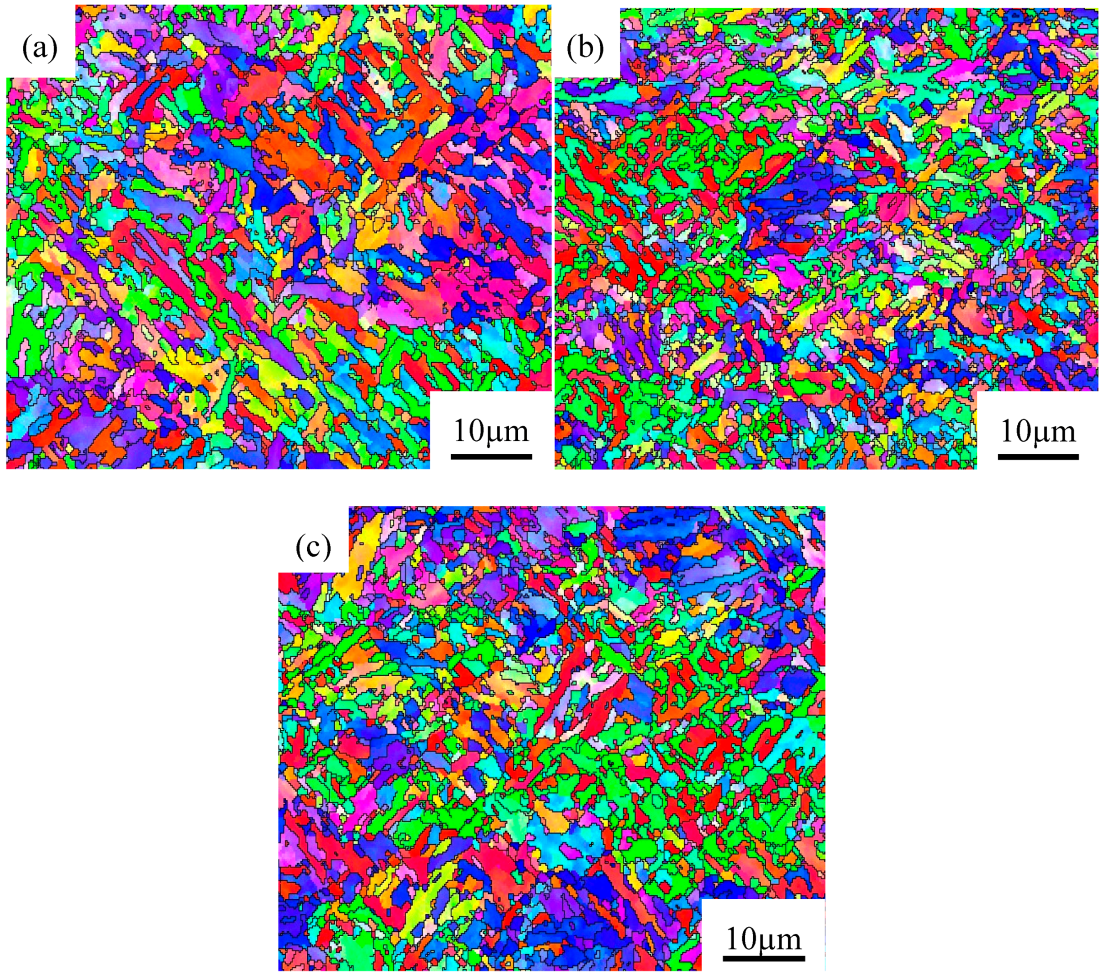
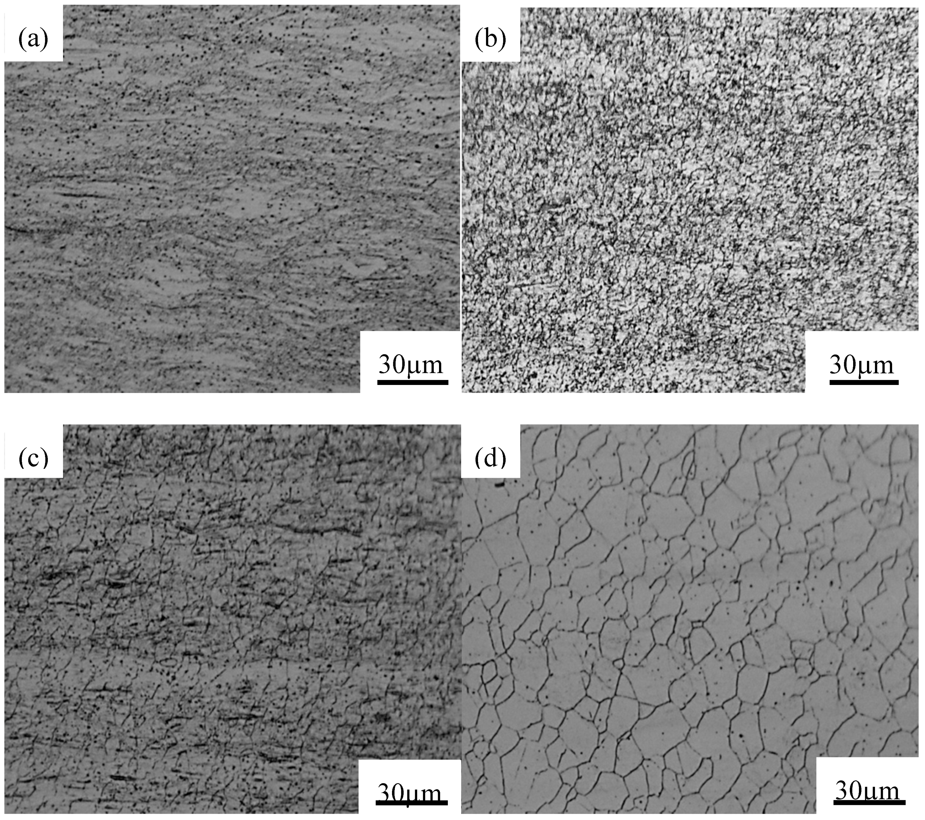
Notably, the power dissipation efficiency values change substantially as A and B increase with increasing strain. We therefore calculated the variation in the efficiency of power dissipation with true strain at deformation temperatures of 1000 and 1150 °C and a strain rate of 0.01 s−1. As shown in Figure 10, as the true strain increases, the peak efficiency of power dissipation increases gradually because the DRX volume fraction increases and consumes a large amount of energy. With further increases of the true strain, the peak efficiency of power dissipation decreases at a true strain of 0.6 at 1000 °C and a true strain of 0.5 at 1150 °C. This behavior has been previously attributed to the coarsening of recrystallized grains [51]. To verify this result, we conducted thermal compression simulation experiments at 1000 °C and true strains of 0.3 and 0.6 and analyzed the microstructure, size and grain boundaries and the average grain size by EBSD. Figure 11 shows the microstructure of three different true strains. Figure 11a shows that at a true strain of 0.3, a significant shear band is caused by flow instability, which affects the mechanical properties of the product after forming. As the true strain increases, this phenomenon disappears and the microstructure tends to be uniform.
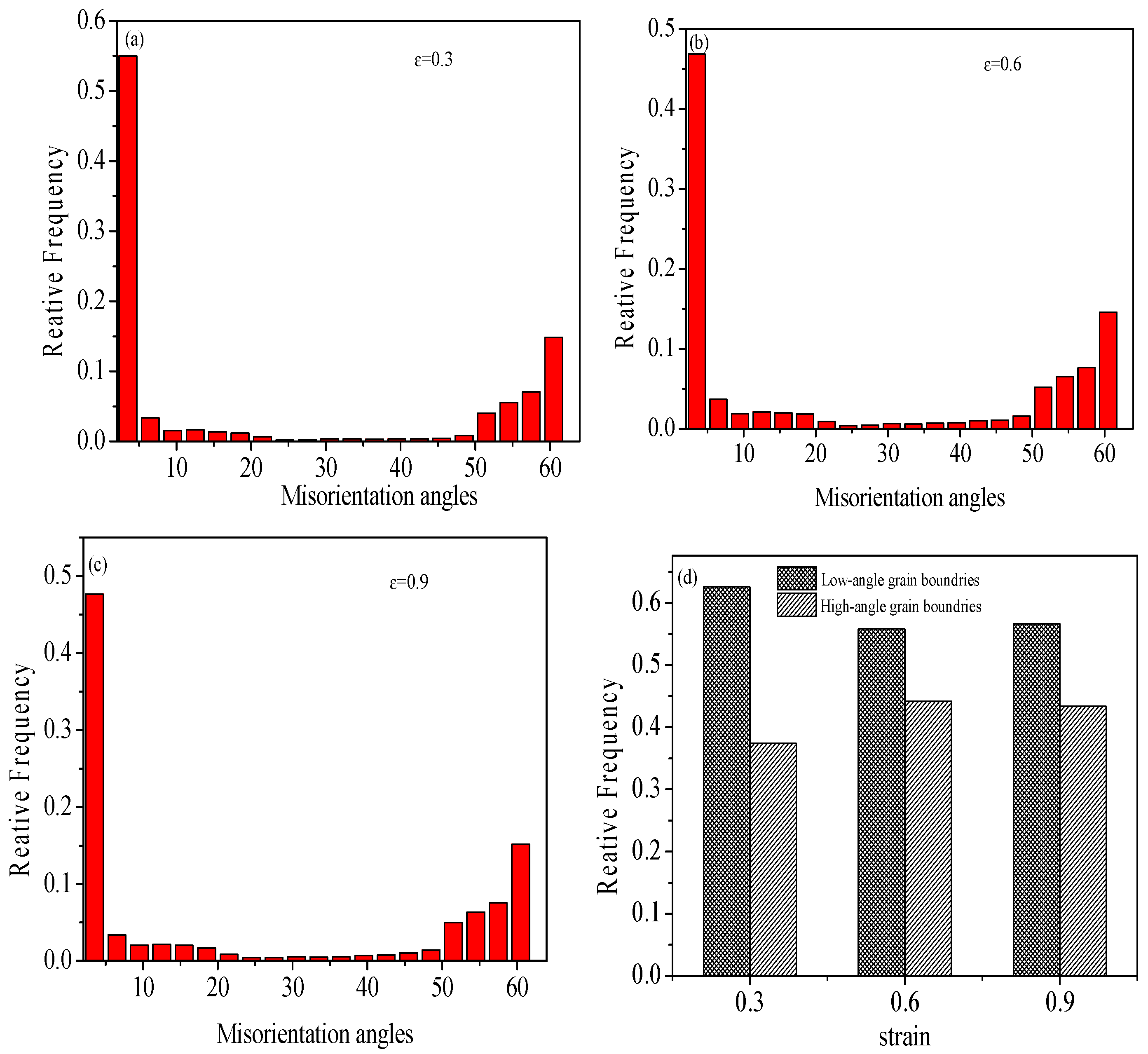
Figure 12a–c shows the type of grain boundary under these three deformation conditions. We calculated the grain boundary distribution under different deformations, as shown in Figure 12d. From Figure 12d, when the true strain is 0.3, the proportion of low-angle grain boundaries (LAGBs) is larger and the proportion of high-angle grain boundaries (HAGBs) is smaller. This result indicates that the recrystallization volume fraction is small at a true strain of 0.3. When the true strain is 0.6, the proportion of LAGBs is substantially reduced and the proportion of HAGBs is significantly increased. Moreover, the number of LAGBs decreases and is approximately the same as the number of HAGBs. This phenomenon can be interpreted on the basis of the mechanism of strain-induced boundary migration, in which LAGBs migrate to random HAGBs and are counteracted or swallowed by HAGBs during the process of DRX [52]. Figure 12 shows that with increasing true strain, the recrystallization volume fraction increases obviously; however, the size and grain-boundary distribution of true strain at 0.9 are not substantially different from those at 0.6. At the same time, the average grain size under the strains of 0.3, 0.6, and 0.9 was 2.044 μm, 1.73 μm, and 1.84 μm, respectively; thus, the grain size appears to first decrease and then increase. This behavior shows that the DRX is almost complete when the true strain is 0.6 and that the recrystallized grains grow when the true strain is 0.9. Through the aforementioned analysis, we can further explain that the growth of the grain at the true strain of 0.9 leads to a decrease in the peak power dissipation efficiency. Because grain-coarsening reduces the mechanical properties of the material, the true strain should not exceed 0.6 at 1000 and 1150 °C and a strain rate of 0.01 s−1.
3.4. Microstructure
The DRX of steel depends on the strain, temperature and strain rate [53,54]. To study the deformation mechanism under different deformation conditions, we observed the microstructure of the material in the flow stability region and the flow instability region. Figure 13 shows the microstructure of the material in the flow stability region. Figure 13a shows that complete DRX occurred at 1050 °C and a strain rate of 0.01 s−1 and that the η in this region is high. The results obtained from the processing map are consistent with the microstructure results. DRX is prone to occur at lower strain rates due to the lower critical strain (i.e., critical dislocation density) required. The nucleation conditions of DRX expressed by dislocation density () and strain rate () can be expressed by the formula [55]:
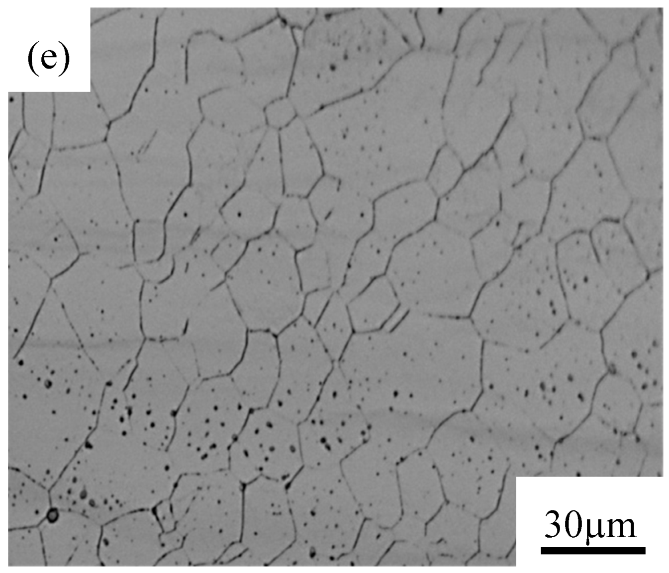
where is the boundary energy, M is the boundary mobility, L is the average slip distance of the dislocations, G is the shear modulus, b is the Burgers vector and K is a constant. According to Equation (20), at a given temperature, DRX nucleation requires a lower (i.e., critical strain) at lower strain-rate conditions. The critical strain of DRX has been reported to increase with increasing strain rate for various materials [56,57]. We observed a similar phenomenon in this work by comparing the critical strain at different strain rates in Table 2. The lower critical strain promotes nucleation of recrystallization, whereas the lower strain rate provides sufficient time for grain-boundary migration, which causes DRX grains to grow further, resulting in accelerated DRX kinetics. As the temperature increases, the recrystallized grains grow, as shown in Figure 13b,c. For the strain rate of 0.1 s−1, the relatively fast deformation speed reduces the time of grain-boundary migration. At the same time, the energy storage during deformation is substantially lower than that at a high strain rate. The recrystallization process becomes slower, and the structure shown in Figure 13d appears. However, a uniform equiaxed grain appears at a strain rate of 1 s−1, as shown in Figure 13e,f. We further analyzed this situation using a strain rate of 10 s−1, as discussed later in this work.
Figure 14 shows the microstructure of the flow instability region under different deformation conditions. As evident from Figure 14a, the lower temperature allows the deformed grains to coexist with the recrystallized grains and the value of η is low (17%) under this condition. Other authors have suggested that this microstrip structure is an unstable phenomenon at high strain rates [58].
This phenomenon is improved at 1000 °C. Figure 14c–e shows that the equiaxed crystal is uniform at a strain rate of 10 s−1 and that the recrystallized grain size increases with increasing deformation temperature. However, this region is marked as an instability region in the processing map. Under this deformation condition, the η value is 28%. This phenomenon has been previously attributed to a high density of dislocations promoting the nucleation of DRX grains [59]. At the same time, the increase of dislocation density and stored energy in a deforming material with increasing strain rate has been reported to be due to a strong dislocation–dislocation interaction and weak recovery [60]. Therefore, more energy is stored in the deformed sample at high strain rates. At the same time, the adiabatic heating effect produced at high strain rates is more pronounced. Moreover, at high strain rates, the time for grain-boundary migration is very short. These reasons together promote the nucleation of DRX. This situation, which occurs at high strain rates, has also appeared in several other reports [15,24,52,61]. At the same time, some scholars have questioned the instability parameters. They have speculated that if a large number of DRX grains are produced at high strain rates, the instability parameters will be difficult to predict under the deformation conditions [61]. Chiba et al. speculated that the value ranges from −1 to 0, that the processing region may be a metastable processing region, and that some instability phenomena may not occur in this region [50]. Meanwhile, we also marked the range of different values from the processing map. At high strain rates, most of the values correspond to metastable processing regions. We consider it a “safe haven” for processing because it helps to maximize production efficiency in industrial production.
4. Conclusions
The hot deformation behavior of H13-mod steel was analyzed by the flow curve, kinetics, processing map and microstructure under the deformation temperature range from 900 °C to 1150 °C and the strain rate range from 0.01 s−1–10 s−1.
The main conclusions are as follows:
- (1)
- In the initial stage of deformation, as the strain increases, the flow stress rapidly increases to a peak. After reaching the peak stress, the flow curve exhibits significant flow softening at low strain rates, mainly related to deformation heating and dynamic changes such as DRV and DRX. At high strain rates, flow softening is reduced by the higher work-hardening rate.
- (2)
- The relationship between peak stress, strain rate, and deformation temperature can be expressed by .
- (3)
- A good linear correlation exists between peak stress (strain), critical stress (strain) stable stress, peak stress and Z parameters.
- (4)
- The relationship between material constants (α, Q, n, and lnA) and true strain in the Arrhenius-type constitutive equation is established by a sixth-order polynomial. The predicted flow stress values of the constitutive equations are in good agreement with the experimental values, indicating that the constitutive equation can accurately estimate the flow stress of H13-mod steel.
- (5)
- The processing maps under different strains were established. The instability region mostly corresponded to high-strain-rate conditions; however, the microstructure did not show any signs of instability at high temperatures and high strain rates. By studying the thermal compression test under different deformation amounts, we determined that the processing temperature is 998–1026 °C and 1140–1150 °C and the strain rate is 0.01–0.02 s−1 and 0.01–0.057 s−1. Moreover, the true strain does not exceed 0.6.
Author Contributions
C.L. and Y.L. conceived and designed the experiments; C.L. performed the experiments and collected the data; C.L., Y.T. and F.Z. analyzed the data; All the authors cooperated in writing this paper.
Funding
This work was supported by National Natural Science Foundation of China with Grant Nos. 51571066 and 51461008, Guizhou science and technology project with Grant Nos. 20165654, 20162326.
Conflicts of Interest
The authors declare no conflict of interest.
References
- Zhang, Z.J.; Zhang, L.; He, J. The status and prospect of shield cutters industry. Cem. Carbide 2015, 32, 340–346. [Google Scholar]
- Rainer, B.; Kurt, K.; Karl-Heinz, O.; Axel, N. Meisselwerkzeug EP0586337A2. 9 March 1994. [Google Scholar]
- Khan, P.L.; Bhivsane, S.V. Experimental Analysis and Investigation of Machining Parameters in Finish Hard Turning of AISI 4340 Steel. Proced. Manuf. 2018, 20, 265–270. [Google Scholar] [CrossRef]
- Jia, X.M.; Chai, J.R. Study on Tribology Performance and Wear Controlling of 9Cr2Mo Steel. Adv. Mater. Res. 2010, 139–141, 414–417. [Google Scholar] [CrossRef]
- Yan, H.; Chen, L.; Ruan, X.M. Tempering process of 5Cr5MoSiV1 steel for shield tools. Trans. Mater. Heat Treat. 2013, 34, 50–55. [Google Scholar]
- Li, S.S.; Liu, Y.H.; Song, Y.L.; Kong, L.; Zhang, R.H.; Li, T.J. Microstructure, mechanical properties and strengthening mechanisms of 5Cr5MoV modified by aluminum. Mater. Des. 2015, 83, 483–492. [Google Scholar] [CrossRef]
- Elias, C.N.; Viana, C.S.D.C. Effect of ausforming on microstructure and hardness of AISI H-13 tool steel modified with niobium. Met. Sci. J. 1992, 8, 785–790. [Google Scholar] [CrossRef]
- Lachenicht, V.; Scharf, G.; Zebrowski, D.; Shalimov, A. Spray forming—A promising process for making high-quality steels and alloys. Metallurgist 2011, 54, 656–668. [Google Scholar] [CrossRef]
- Sahu, S.N.; Harikishore, S.; Koria, S.C. Solidification behaviour of droplets in spray deposition. Powder Metall. 2013, 48, 270–276. [Google Scholar] [CrossRef]
- Grant, P.S. Solidification in Spray Forming. Metall. Mater. Trans. A 2007, 38, 1520–1529. [Google Scholar] [CrossRef]
- Lin, Y.; Mchugh, K.M.; Zhou, Y.; Lavernia, E.J. Microstructure and hardness of spray-formed chromium-containing steel tooling. Scr. Mater. 2006, 55, 581–584. [Google Scholar] [CrossRef]
- Kheirandish, S.; Noorian, A. Effect of Niobium on Microstructure of Cast AISI H13 Hot Work Tool Steel. J. Iron Steel Res. (Int.) 2008, 15, 61–66. [Google Scholar] [CrossRef]
- Molinari, A.; Pellizzari, M.; Gialanella, S.; Straffelini, G.; Stiasny, K.H. Effect of deep cryogenic treatment on the mechanical properties of tool steels. J. Mater. Process. Tech. 2001, 118, 350–355. [Google Scholar] [CrossRef]
- Samantaray, D.; Mandal, S.; Bhaduri, A.K. Optimization of hot working parameters for thermo-mechanical processing of modified 9Cr–1Mo (P91) steel employing dynamic materials model. Mater. Sci. Eng. A 2011, 528, 5204–5211. [Google Scholar] [CrossRef]
- Samantaray, D.; Mandal, S.; Jayalakshmi, M.; Athreya, C.N.; Bhaduri, A.K.; Sarma, V.S. New insights into the relationship between dynamic softening phenomena and efficiency of hot working domains of a nitrogen enhanced 316L(N) stainless steel. Mater. Sci. Eng. A 2014, 598, 368–375. [Google Scholar] [CrossRef]
- Prasad, Y.V.R.K.; Seshacharyulu, T. Modelling of hot deformation for microstructural control. Metall. Rev. 1998, 43, 243–258. [Google Scholar] [CrossRef]
- Venugopal, S.; Mannan, S.L.; Rodriguez, P. Strategy for the design of thermomechanical processes for AISI type 304L stainless steel using dynamic materials model (DMM) stability criteria and model for the evolution of microstructure. J. Mater. Sci. 2004, 39, 5557–5560. [Google Scholar] [CrossRef]
- Dehghan-Manshadi, A.; Hodgson, P.D. Effect of δ-ferrite co-existence on hot deformation and recrystallization of austenite. J. Mater. Sci. 2008, 43, 6272. [Google Scholar] [CrossRef]
- Gavard, L.; Montheillet, F.; Coze, J.L. The Effect of Purity on Dynamic Recrystallization in Austenitic Stainless Steels. Mater. Trans. JIM 2007, 41, 113–115. [Google Scholar] [CrossRef]
- Momeni, A.; Dehghani, K. Characterization of hot deformation behavior of 410 martensitic stainless steel using constitutive equations and processing maps. Mater. Sci. Eng. A 2010, 527, 5467–5473. [Google Scholar] [CrossRef]
- Saboori, A.; Pavese, M.; Biamino, S.; Fino, P.; Lombardi, M. Determination of critical condition for initiation of dynamic recrystallization in Zr-1%Nb alloy. J. Alloy. Compd. 2018, 757, 1–7. [Google Scholar] [CrossRef]
- Wu, H.; Wen, S.P.; Huang, H.; Wu, X.L.; Gao, K.Y.; Wang, W.; Nie, Z.R. Hot deformation behavior and constitutive equation of a new type Al–Zn–Mg–Er–Zr alloy during isothermal compression. Mater. Sci. Eng. A 2016, 651, 415–424. [Google Scholar] [CrossRef]
- Tan, Y.B.; Ma, Y.H.; Zhao, F. Hot deformation behavior and constitutive modeling of fine grained Inconel 718 superalloy. J. Alloy. Compd. 2018, 741, 85–96. [Google Scholar] [CrossRef]
- Zhang, C.; Zhang, L.; Shen, W.; Liu, C.; Xia, Y.; Li, R. Study on constitutive modeling and processing maps for hot deformation of medium carbon Cr–Ni–Mo alloyed steel. Mater. Des. 2016, 90, 804–814. [Google Scholar] [CrossRef]
- Yin, F.; Hua, L.; Mao, H.; Han, X. Constitutive modeling for flow behavior of GCr15 steel under hot compression experiments. Mater. Des. 2013, 43, 393–401. [Google Scholar] [CrossRef]
- Ren, F.C.; Chen, J.; Chen, F. Constitutive modeling of hot deformation behavior of X20Cr13 martensitic stainless steel with strain effect. Trans. Nonferrous Met. Soc. China 2014, 24, 1407–1413. [Google Scholar] [CrossRef]
- Sivaprasad, P.V.; Venugopal, S.; Venugopal, S.; Maduraimuthu, V.; Vasudevan, M.; Mannan, S.L.; Prasad, Y.V.R.K.; Chaturvedi, R.C. Validation of processing maps for a 15Cr–15Ni–2.2Mo–0.3Ti austenitic stainless steel using hot forging and rolling tests. J. Mater. Process. Tech. 2003, 132, 262–268. [Google Scholar] [CrossRef]
- Rao, K.P.; Prasad, Y.V.R.K.; Suresh, K.; Dharmendra, C.; Hort, N.; Kainer, K.U. Compressive Strength and Hot Deformation Behavior of TX32 Magnesium Alloy with 0.4% Al and 0.4% Si Additions; Springer International Publishing: Berlin, Germany, 2011; pp. 6964–6970. [Google Scholar]
- Sen, I.; Kottada, R.S.; Ramamurty, U. High temperature deformation processing maps for boron modified Ti–6Al–4V alloys. Mater. Sci. Eng. A 2010, 527, 6157–6165. [Google Scholar] [CrossRef]
- Han, Y.; Yan, S. Effects of temperature and strain rate on the dynamic recrystallization of a medium-high-carbon high-silicon bainitic steel during hot deformation. Vacuum 2018, 148, 78–87. [Google Scholar] [CrossRef]
- Xu, L.; Chen, L.; Chen, G.; Wang, M. Hot deformation behavior and microstructure analysis of 25Cr3Mo3NiNb steel during hot compression tests. Vacuum 2018, 147, 8–17. [Google Scholar] [CrossRef]
- Chen, X.M.; Lin, Y.C.; Wen, D.X.; Zhang, J.L.; He, M. Dynamic recrystallization behavior of a typical nickel-based superalloy during hot deformation. Mater. Des. 2014, 57, 568–577. [Google Scholar] [CrossRef]
- Sellars, C.M.; Tegart, W.J.M.G. Relationship between strength and structure in deformation at elevated temperatures. Mem. Sci. Rev. Met. 1966, 63. [Google Scholar]
- Zener, C.; Hollomon, J.H. Effect of Strain Rate Upon Plastic Flow of Steel. J. Appl. Phy. 1944, 15, 22–32. [Google Scholar] [CrossRef]
- Lin, Y.C.; Xia, Y.C.; Chen, X.M.; Chen, M.S. Constitutive descriptions for hot compressed 2124-T851 aluminum alloy over a wide range of temperature and strain rate. Comput. Mater. Sci. 2010, 50, 227–233. [Google Scholar] [CrossRef]
- Cai, J.; Li, F.; Liu, T.; Chen, B.; He, M. Constitutive equations for elevated temperature flow stress of Ti–6Al–4V alloy considering the effect of strain. Mater. Des. 2011, 32, 1144–1151. [Google Scholar] [CrossRef]
- Samantaray, D.; Phaniraj, C.; Mandal, S.; Bhaduri, A.K. Strain dependent rate equation to predict elevated temperature flow behavior of modified 9Cr-1Mo (P91) steel. Mater. Sci. Eng. A 2011, 528, 1071–1077. [Google Scholar] [CrossRef]
- Ashtiani, H.R.R.; Parsa, M.H.; Bisadi, H. Constitutive equations for elevated temperature flow behavior of commercial purity aluminum. Mater. Sci. Eng. A 2012, 545, 61–67. [Google Scholar] [CrossRef]
- Mandal, S.; Rakesh, V.; Sivaprasad, P.V.; Venugopal, S.; Kasiviswanathan, K.V. Constitutive equations to predict high temperature flow stress in a Ti-modified austenitic stainless steel. Mater. Sci. Eng. A 2009, 500, 114–121. [Google Scholar] [CrossRef]
- Abbasi-Bani, A.; Zarei-Hanzaki, A.; Pishbin, M.H.; Haghdadi, N. A comparative study on the capability of Johnson–Cook and Arrhenius-type constitutive equations to describe the flow behavior of Mg–6Al–1Zn alloy. Mech. Mater. 2014, 71, 52–61. [Google Scholar] [CrossRef]
- Liao, C.; Wu, H.; Wu, C.; Zhu, F.; Lee, S. Hot deformation behavior and flow stress modeling of annealed AZ61 Mg alloys. Prog. Nat. Sci. Mater. Int. 2014, 24, 253–265. [Google Scholar] [CrossRef]
- Junior, J.; Moreira, A.; Balancin, O. Prediction of steel flow stresses under hot working conditions. Mater. Res. 2005, 8, 309–315. [Google Scholar] [CrossRef]
- Prasad, Y.V.R.K.; Gegel, H.L.; Doraivelu, S.M.; Malas, J.C.; Morgan, J.T.; Lark, K.A.; Barker, D.R. Modeling of dynamic material behavior in hot deformation: Forging of Ti-6242. Metall. Trans. A 1984, 15, 1883–1892. [Google Scholar] [CrossRef]
- Prasad, Y.V.R.K. Author’s reply: Dynamic materials model: Basis and principles. Metall. Mater. Trans. A 1996, 27, 235–236. [Google Scholar] [CrossRef]
- Murty, S.V.S.N.; Rao, B.N. Ziegler’s Criterion on the Instability Regions in Processing Maps. J. Mater. Sci. Lett. 1998, 17, 1203–1205. [Google Scholar] [CrossRef]
- Wang, Y.; Pan, Q.; Song, Y.; Li, C.; Li, Z. Hot deformation and processing maps of X-750 nickel-based superalloy. Mater. Des. 2013, 51, 154–160. [Google Scholar] [CrossRef]
- Yang, Z.; Zhang, F.; Zheng, C.; Zhang, M.; Lv, B.; Qu, L. Study on hot deformation behaviour and processing maps of low carbon bainitic steel. Mater. Des. 2015, 66, 258–266. [Google Scholar] [CrossRef]
- Quan, G.Z.; Zhao, L.; Chen, T.; Wang, Y.; Mao, Y.P.; Lv, W.Q.; Zhou, J. Identification for the optimal working parameters of as-extruded 42CrMo high-strength steel from a large range of strain, strain rate and temperature. Mater. Sci. Eng. A 2012, 538, 364–373. [Google Scholar] [CrossRef]
- Peng, X.; Guo, H.; Shi, Z.; Qin, C.; Zhao, Z.; Yao, Z. Study on the hot deformation behavior of TC4-DT alloy with equiaxed α + β starting structure based on processing map. Mater. Sci. Eng. A 2014, 605, 80–88. [Google Scholar] [CrossRef]
- Chiba, A.; Lee, S.H.; Matsumoto, H.; Nakamura, M. Construction of processing map for biomedical Co–28Cr–6Mo–0.16N alloy by studying its hot deformation behavior using compression tests. Mater. Sci. Eng. A 2009, 513, 286–293. [Google Scholar] [CrossRef]
- Balasubrahmanyam, V.V.; Prasad, Y.V.R.K. Deformation behaviour of beta titanium alloy Ti–10V–4.5Fe–1.5Al in hot upset forging. Mater. Sci. Eng. A 2002, 336, 150–158. [Google Scholar] [CrossRef]
- Sun, H.; Sun, Y.; Zhang, R.; Wang, M.; Tang, R.; Zhou, Z. Hot deformation behavior and microstructural evolution of a modified 310 austenitic steel. Mater. Des. 2014, 64, 374–380. [Google Scholar] [CrossRef]
- Mandal, S.; Sivaprasad, P.V.; Dube, R.K. Kinetics, mechanism and modelling of microstructural evolution during thermomechanical processing of a 15Cr–15Ni–2.2Mo–Ti modified austenitic stainless steel. J. Mater. Sci. 2007, 42, 2724–2734. [Google Scholar] [CrossRef]
- Doherty, R.D.; Hughes, D.A.; Humphreys, F.J.; Jonas, J.J.; Jensen, D.J.; Kassner, M.E.; King, W.E.; Mcnelley, T.R.; Mcqueen, H.J.; Rollett, A.D. Current issues in recrystallization: a review. Mater. Sci. Eng. A 1997, 238, 219–274. [Google Scholar] [CrossRef] [Green Version]
- Sample, V.M.; Fitzsimons, G.L.; Deardo, A.J. Dynamic softening of copper during deformation at high temperatures and strain rates. Acta Metall. 1987, 35, 367–379. [Google Scholar] [CrossRef]
- Mejía, I.; Bedolla-Jacuinde, A.; Maldonado, C.; Cabrera, J.M. Determination of the critical conditions for the initiation of dynamic recrystallization in boron microalloyed steels. Mater. Sci. Eng. A 2011, 528, 4133–4140. [Google Scholar] [CrossRef]
- Shaban, M.; Eghbali, B. Determination of critical conditions for dynamic recrystallization of a microalloyed steel. Mater. Sci. Eng. A 2010, 527, 4320–4325. [Google Scholar] [CrossRef]
- Babu, K.A.; Mandal, S.; Athreya, C.N.; Shakthipriya, B.; Sarma, V.S. Hot deformation characteristics and processing map of a phosphorous modified super austenitic stainless steel. Mater. Des. 2017, 115, 262–275. [Google Scholar] [CrossRef]
- Dehghan-Manshadi, A.; Barnett, M.R.; Hodgson, P.D. Recrystallization in AISI 304 austenitic stainless steel during and after hot deformation. Mater. Sci. Eng. A 2008, 485, 664–672. [Google Scholar] [CrossRef]
- Mandal, S.; Jayalakshmi, M.; Bhaduri, A.K.; Sarma, V.S. Effect of Strain Rate on the Dynamic Recrystallization Behavior in a Nitrogen-Enhanced 316L(N). Metall. Mater. Trans. A 2014, 45, 5645–5656. [Google Scholar] [CrossRef]
- Favre, J.; Koizumi, Y.; Chiba, A.; Fabregue, D.; Maire, E. Deformation Behavior and Dynamic Recrystallization of Biomedical Co-Cr-W-Ni (L-605) Alloy. Metall. Mater. Trans. A Phys. Metall. Mater. Sci. 2013, 44, 2819–2830. [Google Scholar] [CrossRef]
Figure 1.
Stress-strain curves for the H13-mod steel deformed at strain rates of (a) 0.01 s−1; (b) 0.1 s−1; (c) 1 s−1 and (d) 10 s−1.
Figure 1.
Stress-strain curves for the H13-mod steel deformed at strain rates of (a) 0.01 s−1; (b) 0.1 s−1; (c) 1 s−1 and (d) 10 s−1.

Figure 2.
The extent of the flow softening () as a function of deformation temperature at various strain rates.
Figure 2.
The extent of the flow softening () as a function of deformation temperature at various strain rates.

Figure 3.
Work hardening rate curve.

Figure 4.
Relationships between (a) and (b) and (c) and (d) and lnZ (e) lnZ and .


Figure 5.
Variation of (a) α, (b) lnA, (c) n and (d) Q with true strain for the H13-mod steel.

Figure 6.
Predicted flow curves and its comparison with those experimentally obtained at strain rates of (a) 0.01 s−1, (b) 0.1 s−1, (c) 1 s−1 and (d) 10 s−1 in the deformation temperature range of 900–1150 °C.
Figure 6.
Predicted flow curves and its comparison with those experimentally obtained at strain rates of (a) 0.01 s−1, (b) 0.1 s−1, (c) 1 s−1 and (d) 10 s−1 in the deformation temperature range of 900–1150 °C.

Figure 7.
Correlation between the predicted and experimental flow stresses for the strain range of 0.05–0.9 (at intervals of 0.05) over the entire strain rate (0.01–10 s−1) and deformation temperature range (900–1150 °C).
Figure 7.
Correlation between the predicted and experimental flow stresses for the strain range of 0.05–0.9 (at intervals of 0.05) over the entire strain rate (0.01–10 s−1) and deformation temperature range (900–1150 °C).

Figure 8.
Dependence of mechanical parameters on Zener–Hollomon parameter.

Figure 9.
Processing maps for the H13-mod steel at true strains of (a) 0.4, (b) 0.5, (c) 0.6, (d) 0.7, (e) 0.8, and (f) 0.9.
Figure 9.
Processing maps for the H13-mod steel at true strains of (a) 0.4, (b) 0.5, (c) 0.6, (d) 0.7, (e) 0.8, and (f) 0.9.


Figure 10.
Variation in the efficiency of power dissipation with true strain at the deformation temperature of 1100 °C and 1150 °C and the strain rate of 0.1 s−1.
Figure 10.
Variation in the efficiency of power dissipation with true strain at the deformation temperature of 1100 °C and 1150 °C and the strain rate of 0.1 s−1.

Figure 11.
EBSD maps of the hot compressed specimens of H13-mod steel at the deformation temperature of 1100 °C, strain rate of 0.01 s−1 and true strain of (a) 0.3; (b) 0.6; (c) 0.9.
Figure 11.
EBSD maps of the hot compressed specimens of H13-mod steel at the deformation temperature of 1100 °C, strain rate of 0.01 s−1 and true strain of (a) 0.3; (b) 0.6; (c) 0.9.

Figure 12.
Grain orientation image of H13-mod steel at the deformation temperature of 1100 °C, strain rate of 0.01 s−1 and true strain of (a) 0.3; (b) 0.6; (c) 0.9; and (d) grain boundary distribution under different deformations.
Figure 12.
Grain orientation image of H13-mod steel at the deformation temperature of 1100 °C, strain rate of 0.01 s−1 and true strain of (a) 0.3; (b) 0.6; (c) 0.9; and (d) grain boundary distribution under different deformations.

Figure 13.
Optical microstructures of H13-mod steel in the flow stability region at deformation conditions of (a) 1050 °C, 0.01 s−1, (b) 1100 °C, 0.01 s−1 (c) 1150 °C, 0.01 s−1, (d) 1150 °C, 0.1 s−1, (e) 1100 °C, 1 s−1 (f) 1150 °C, 1 s−1.
Figure 13.
Optical microstructures of H13-mod steel in the flow stability region at deformation conditions of (a) 1050 °C, 0.01 s−1, (b) 1100 °C, 0.01 s−1 (c) 1150 °C, 0.01 s−1, (d) 1150 °C, 0.1 s−1, (e) 1100 °C, 1 s−1 (f) 1150 °C, 1 s−1.

Figure 14.
Optical microstructures of H13-mod steel in the flow instability region at deformation conditions of (a) 950 °C, 1 s−1, (b) 1000 °C, 1 s−1, (c) 1050 °C, 10 s−1, (d) 1100 °C, 10 s−1, (e) 1150 °C, 10 s−1.
Figure 14.
Optical microstructures of H13-mod steel in the flow instability region at deformation conditions of (a) 950 °C, 1 s−1, (b) 1000 °C, 1 s−1, (c) 1050 °C, 10 s−1, (d) 1100 °C, 10 s−1, (e) 1150 °C, 10 s−1.


Table 1.
Chemical composition of the H13-mod steel (wt %).
| C | Si | Mn | Cr | Mo | V | P | S | Fe |
|---|---|---|---|---|---|---|---|---|
| 0.49 | 0.86 | 0.41 | 5.15 | 1.26 | 0.84 | 0.045 | 0.0084 | Bal |
Table 2.
The values of the various parameters.
| Temperature/°C | |||||||
|---|---|---|---|---|---|---|---|
| 900 °C | 0.01 | 218.65 | 231.19 | 248.64 | 201.63 | 0.144 | 0.277 |
| 0.1 | 253.87 | 267.61 | 289.02 | 250.49 | 0.147 | 0.29 | |
| 1 | 274.58 | 301.85 | 325.99 | 282.31 | 0.142 | 0.332 | |
| 10 | 313.66 | 348.43 | 400.52 | 324.84 | 0.141 | 0.356 | |
| 950 °C | 0.01 | 136.74 | 154.19 | 161.31 | 135.45 | 0.115 | 0.305 |
| 0.1 | 192.91 | 200.68 | 221.23 | 189.31 | 0.137 | 0.267 | |
| 1 | 217.64 | 250.42 | 265.02 | 243.15 | 0.115 | 0.31 | |
| 10 | 261.58 | 294.75 | 323.79 | 264.32 | 0.147 | 0.339 | |
| 1000 °C | 0.01 | 108.58 | 117.18 | 119.64 | 100.35 | 0.101 | 0.239 |
| 0.1 | 157.74 | 172.09 | 180.23 | 147.73 | 0.115 | 0.27 | |
| 1 | 180.89 | 206.75 | 251.23 | 200.81 | 0.115 | 0.283 | |
| 10 | 225.78 | 246.52 | 258.2 | 223.48 | 0.122 | 0.3 | |
| 1050 °C | 0.01 | 81.874 | 86.164 | 86.96 | 67.33 | 0.09 | 0.2 |
| 0.1 | 118.22 | 121.04 | 138.89 | 97.99 | 0.109 | 0.223 | |
| 1 | 150.52 | 169.4 | 187.83 | 158.54 | 0.115 | 0.3 | |
| 10 | 204.98 | 225.84 | 245.16 | 210.35 | 0.109 | 0.305 | |
| 1100 °C | 0.01 | 71.91 | 77.691 | 84.84 | 56.62 | 0.1 | 0.205 |
| 0.1 | 101.52 | 102.24 | 109.72 | 91.91 | 0.115 | 0.232 | |
| 1 | 123.01 | 140.56 | 144.02 | 138.02 | 0.109 | 0.306 | |
| 10 | 158.06 | 175.08 | 176.12 | 172.02 | 0.106 | 0.347 | |
| 1150 °C | 0.01 | 50.88 | 51.81 | 54.23 | 41.12 | 0.11 | 0.187 |
| 0.1 | 80.59 | 84.71 | 88.12 | 70.84 | 0.111 | 0.22 | |
| 1 | 110.02 | 115.35 | 152.1 | 145.05 | 0.11 | 0.318 | |
| 10 | 137.04 | 149.54 | 248.64 | 201.63 | 0.11 | 0.31 |
Table 3.
Activation energy of deformation Q (kJ/mol), stress exponent n, materials constants A and a during hot deformation of the H13-mod steel.
Table 3.
Activation energy of deformation Q (kJ/mol), stress exponent n, materials constants A and a during hot deformation of the H13-mod steel.
| Parameters | Strain | ||||||||
|---|---|---|---|---|---|---|---|---|---|
| 0.05 | 0.1 | 0.15 | 0.2 | 0.25 | 0.3 | 0.35 | 0.4 | 0.45 | |
| α | 0.0073 | 0.0065 | 0.0063 | 0.0061 | 0.0060 | 0.0060 | 0.0060 | 0.0060 | 0.0061 |
| n | 9.65 | 8.15 | 7.68 | 7.40 | 7.13 | 6.96 | 6.77 | 6.60 | 6.48 |
| Q | 651.38 | 601.604 | 589.4 | 578.06 | 569.434 | 562.07 | 556.13 | 548.7 | 544.8 |
| lnA | 58.73 | 53.82 | 52.53 | 51.44 | 50.65 | 50.03 | 49.54 | 48.91 | 48.59 |
| 0.5 | 0.55 | 0.6 | 0.65 | 0.7 | 0.75 | 0.8 | 0.85 | 0.9 | |
| α | 0.00613 | 0.0062 | 0.00627 | 0.00633 | 0.00639 | 0.00641 | 0.00643 | 0.00642 | 0.00643 |
| n | 6.36 | 6.29 | 6.23 | 6.12 | 6.10 | 6.08 | 6.08 | 6.08 | 6.19 |
| Q | 540.18 | 538.4 | 534.84 | 527.809 | 520.96 | 515.71 | 508.94 | 499.95 | 497.838 |
| lnA | 48.20 | 48.07 | 47.75 | 47.08 | 46.45 | 45.96 | 45.32 | 44.46 | 44.23 |
Table 4.
Polynomial fitting results of a, n, Q and lnA for the H13-mod steel.
| Coefficient | α | n | Q | lnA |
|---|---|---|---|---|
| k0 | 0.009 | 12.115 | 730.780 | 66.618 |
| k1 | −0.033 | −66.698 | −2172.206 | −214.485 |
| k2 | 0.176 | 382.054 | 12,774.327 | 1242.688 |
| k3 | −0.506 | −1159.418 | −40,380.106 | −3853.728 |
| k4 | 0.806 | 1864.244 | 67,955.171 | 6394.677 |
| k5 | −0.659 | −1505.628 | −57,533.393 | −5363.214 |
| k6 | 0.214 | 481.334 | 19,193.203 | 1777.945 |
© 2018 by the authors. Licensee MDPI, Basel, Switzerland. This article is an open access article distributed under the terms and conditions of the Creative Commons Attribution (CC BY) license (http://creativecommons.org/licenses/by/4.0/).
Share and Cite
MDPI and ACS Style
Li, C.; Liu, Y.; Tan, Y.; Zhao, F. Hot Deformation Behavior and Constitutive Modeling of H13-Mod Steel. Metals 2018, 8, 846. https://doi.org/10.3390/met8100846
AMA Style
Li C, Liu Y, Tan Y, Zhao F. Hot Deformation Behavior and Constitutive Modeling of H13-Mod Steel. Metals. 2018; 8(10):846. https://doi.org/10.3390/met8100846
Chicago/Turabian StyleLi, Changmin, Yuan Liu, Yuanbiao Tan, and Fei Zhao. 2018. "Hot Deformation Behavior and Constitutive Modeling of H13-Mod Steel" Metals 8, no. 10: 846. https://doi.org/10.3390/met8100846
Note that from the first issue of 2016, this journal uses article numbers instead of page numbers. See further details here.