Grain Refinement by Extension Twin in Mg Alloy during Asymmetrical Rolling

Plasticity Control & Mechanical Modeling Lab., School of Materials Science & Engineering, Yeungnam University, Gyeongsan 38541, Korea
*
Author to whom correspondence should be addressed.
†
These authors contributed equally to this work.
Metals 2018, 8(11), 891; https://doi.org/10.3390/met8110891
Submission received: 17 October 2018
/
Revised: 28 October 2018
/
Accepted: 30 October 2018
/
Published: 1 November 2018
(This article belongs to the Special Issue Non-Ferrous Metallic Materials)
Abstract
:The work looked into the grain refinement process of Mg alloy during asymmetrical rolling with a focus on the role of twin. The present sample was deformed at ambient temperature by single operation with the height reduction of 50% at the roll speed ratio of 1:4 for the upper and lower rolls having the same dimension. From the electron backscatter diffraction analysis in the surface region where intense shear strain was imparted, a number of {} extension twins with a width of ~1 µm were detected clearly in most of the deformed grains. Moreover, the average misorientation angle of the deformed grains in the top region was found to be ~32°, which was two times higher than that in the center area where the extension twin was detected rarely. As a result, the microstructure in the top region was refined significantly down to be ~1.1 µm with an aid of twin activities that would be discussed in this study.
1. Introduction
Mg and its alloys have received great interest nowadays due to their light weight and high specific strength; hence, they are very attractive in applications such as automotive, railway, and aerospace industries [1,2]. Microstructure with fine grains as well as high angle boundaries would be favored mechanically because high strength was originated from grain refinement while good formability was due to the role of grain boundary as a sink of lattice dislocations [3,4,5]. As such, the deformation-induced grain subdivision was suggested to be major mechanism, which would be achieved by severe plastic deformation (SPD) methods [6,7,8,9]. In case of Mg-3%Al-1%Zn (AZ31) alloys, a range of grain sizes (1–5 μm) have been reported with respect to the processing temperature. Despite the fact that the twin offered not only grain segmentation but also facilitated an increase in misorientation angle between any two grains during deformation, less attention was paid to the twinning process that affected grain refinement in hexagonal close-packed (hcp) metals where most slips took place rarely except basal slip at room temperature [10,11]. This fact was mainly attributed to a difficulty in forming deformation twins, in particular, at grains with strong basal orientation in Mg alloys.
As one of the SPD methods, asymmetrical rolling (AR), in which the speeds of two working rolls varied, was known to be desirable for, more or less, overcoming the dimensional shortcoming of the sample consisting of fine grains. More interestingly, this method was allowed (i) to facilitate the formation of grains with various orientations and (ii) to trigger the formation of extension twins even in the inside of grain with strong basal orientation due to intense shear strain, which was in contrast to the conventional rolling [12,13,14].
Therefore, the present work investigates the grain refinement of AZ31 Mg alloy with an aid of twin activity that might be activated by ‘single’ AR with the height reduction of 50% at the roll speed ratio of 1:4 for the upper and lower rolls, respectively. It is likely that fine grains with high angle grain boundaries will be achieved by the existence of extension twins {} in the deformed grains. This phenomenon is discussed in relation to the microstructural characterizations utilizing electron backscatter diffraction (EBSD).
2. Experimental Procedures
The material used in the study was an AZ31 Mg alloy sample with a chemical composition of 2.89 Al, 0.96 Zn, 0.31 Mn, 0.15 Fe, 0.12 Si, and balance Mg (in wt.%). The samples were machined into plate-type samples with dimensions of 70 30 4 mm. The present sample was heated to 673 K for 24 h to obtain a fully annealed microstructure with globular grains. AR was performed using two working rolls with the same diameter of 220 mm, which rotated at a roll speed ratio of 1:4 for the lower and upper rolls, respectively, under the condition that the velocity of the lower roll was fixed to ~5 m/min. AR was stopped before the sheet was rolled completely, so that three different areas in the deformed sample were obtained as shown in Figure 1a,b. The microstructure was observed in the field-emission scanning electron microscope (FE-SEM) (Hitachi S-4800, Hitachi, Tokyo, Japan) with an accelerating voltage of 15 kV. The EBSD observations were conducted at a step size of 0.02 µm. The orientation information taken from EBSD (EDAX Inc., Mahwah, NJ, USA) was analyzed using the orientation imaging microscopy (OIM) analyzer (TexSem Lab., Provo, UT, USA).
3. Results and Discussion
3.1. AR Deformation
Figure 1 shows the schematic illustration of AZ31 Mg alloy deformed by AR where the process was paused on a sudden before the entire sample was deformed completely. Three different areas were the un-deformed, under-deformed, and as-deformed regions as shown in Figure 1a. The un-deformed and as-deformed areas implied the conditions before and after AR. The under-deformed area was a main focus for EBSD observation of interest. In normal, AR strain (ε) would be calculated according to the equation reported by the present authors [15]:
where r and φ are the thickness reduction and characteristics shear angle by AR. The distribution of AR strain in the under-deformed area was calculated based on a finite element method as presented in Figure 1b [16]. The specific area for microstructural observation was selected by several reasons. First, the estimated amounts of strain in the center and bottom areas remained unchanged significantly. This implied that the contribution of shear strain to the total strain would be negligible except the top area. Second, a significant difference in equivalent strain was found between the center and top area due to the contribution of shear deformation by AR. Thus, the microstructure in the top area experienced relatively higher amount of strain than that in the others.
3.2. Deformation Twin
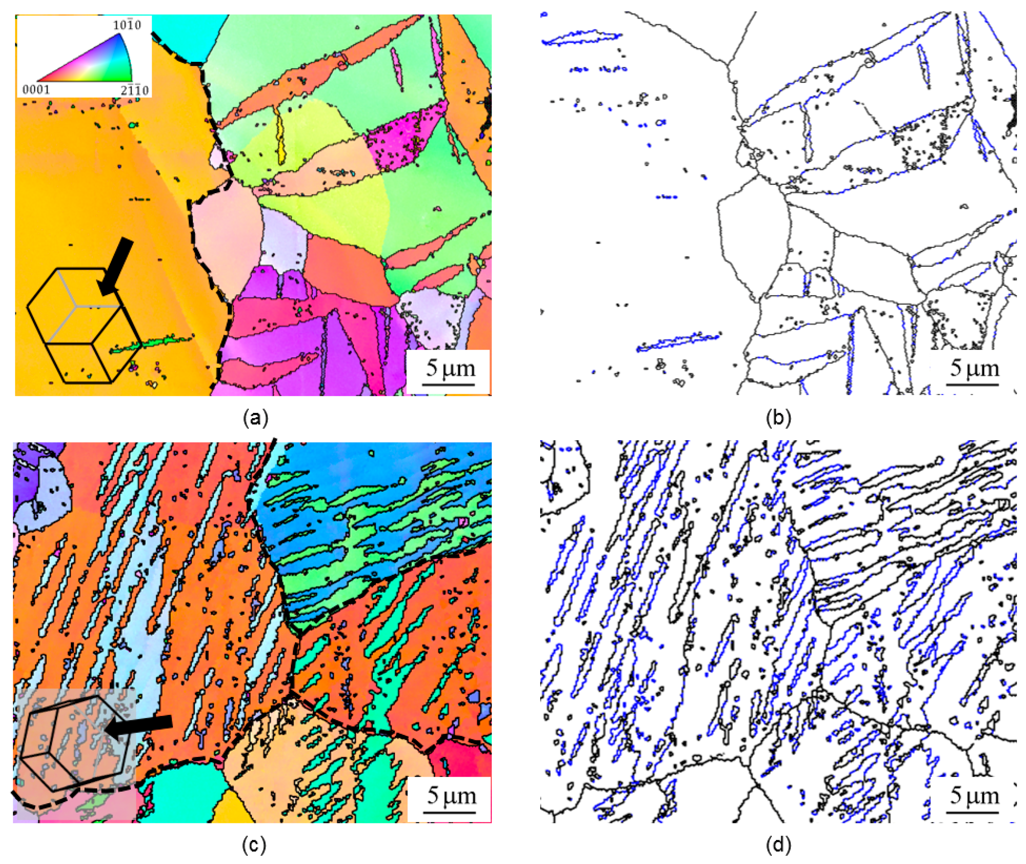
Figure 2 displays the microstructure of the deformed sample in the center and top areas at the early stage of deformation where a number of deformation twins were nucleated [17,18]. Figure 2a shows the inverse pole figure (IPF) image in the center area consisting of a coarse grain with strong basal orientation and some neighbouring grains with weak basal orientation. The yellow grain with strong basal was characterized with its direction of c-axis being nearly parallel to the normal direction (ND), whereas several grains with weak basal were determined with their c-axis being perpendicular to ND. In Mg alloys, the twin boundaries would be discriminated by means of grain boundary (GB) map. Figure 2b shows the GB map revealing the boundaries of the regular grains and twins that were represented as black and blue lines, respectively. It was shown from morphologies that the grains with strong basal contained no twin inside. This differed clearly from the neighbouring grains with weak basal orientation. These twin boundaries detected would be {} extension-typed of twin. Thus, extension twin would be absent in grains with strong basal orientation. Irrespective of basal orientation, a number of extension twins were detected inside most of the deformed grains in the top region, which was affected by local shear deformation imparted during AR. The similar result was reported earlier when extension twin occurred in response to local anomalous stress states [19]. Extension twin {} corresponding to specific misorientation of ~86° was used to tailor mechanical properties since such twin would store the granular dislocation and work also as a dislocation barrier, affecting the hardening response in hcp metals during deformation [20,21,22].
3.3. Deformed Microstructure
The fraction of twin formed inside grain would depend on the initial orientation of the parent grain. In case of extension twin, if the parent grain was positioned with the c-axis perpendicular to the compression direction, the extension twin would appear with ease [23]. Thus, the fraction of the twin would be activated depending on the parent grain whose orientation varied based on the angle between c-axis and ND as shown in Figure 3a. In the top region, the extension twin formed with intensity higher than 20 in both strong and weak basal orientations. This was in contrast to the case in the center region where the twin was absent wholly in grains with an angle between c-axis and ND ranging from 0 to 40°. This would result in a significant difference in the fraction of deformation twin between the center and top regions. The distributions of boundary misorientation in the center and top regions are presented in Figure 3b. The average misorientations in the center and top areas was observed to be ~33° and ~51°. It was inferred that the high average misorientation was attributed to the broad range of grain orientation as well as to the inherent misorientation of extension twin itself.
Figure 4 presents the microstructure at the late stage where the sample was located at the distance away from 8 mm as seen in Figure 1b. From Figure 4a, a coarse basal grain with diameter of ~10 µm was found in the center area. Figure 5b shows the GB map with two types of boundaries. The boundaries with black color belonged to the boundaries with misorientation smaller than ~70° while the boundaries with blue color belonged to the boundaries with misorientation of ~70° or higher. Figure 4c,d shows the EBSD maps of the sample in the top area. It could be seen that most grains were refined and, moreover, the fraction of high angle misorientation was relatively higher than in the center area. Figure 5 shows the misorientation and the grain size distributions in the center and top areas. The average misorientations in the center and top areas were observed to be ~15° and ~32° (Figure 5a). In addition, the average grain sizes in the center and top regions were found to be ~3.1 and ~1.1 µm (Figure 5b). Therefore, these microstructural differences were originated from the different formation of extension twins in AZ 31 Mg alloys deformed via AR.
4. Conclusions
The present study investigated the grain refinement of AZ31 Mg alloy during AR by taking an extension twin of {} into account. After being deformed by a single AR with the height reduction of 50% at the roll speed ratio of 1:4 for the upper and lower rolls, the deformed grains found in the region close to the surface would exhibit extension twins corresponding to certain misorientation angles of ~86.3° in EBSD maps. At the late stage of deformation, the average misorientation angle of the deformed grains increased up to ~32° in the top region, which was two times higher than that in the center area. In addition, the local microstructure in the top region was refined down to ~1.1 µm in diameter by the initial activation of extension twins.
Author Contributions
I.P.W. and H.W.Y. equally contributed to this work as a first author. Conceptualization: I.P.W., H.W.Y., and Y.G.K.; Validation: I.P.W., H.W.Y., and Y.G.K.; Formal Analysis: I.P.W., H.W.Y., and Y.G.K.; Investigation: I.P.W, H.W.Y., D.K.Y., and M.P.K.; Writing—Review and Editing: I.P.W., M.P.K., and Y.G.K.; Supervision: Y.G.K.
Funding
This research was supported mainly by the Basic Science Research Program through the National Research Foundation of Korea (NRF) funded by the Ministry of Education (MOE), Republic of Korea (NRF-2017R1D1A1A09000921).
Conflicts of Interest
The authors declare no conflict of interest.
References
- Ko, Y.G.; Hamad, K. Structural Features and mechanical properties of AZ31 Mg Alloy warm-deformed by differential speed rolling. J. Alloy. Compd. 2018, 744, 96–103. [Google Scholar] [CrossRef]
- Hamad, K.; Ko, Y.G. A cross-shear deformation for optimizing the strength and ductility of AZ31 magnesium alloys. Sci. Rep. 2016, 6, 29954. [Google Scholar] [CrossRef] [PubMed] [Green Version]
- Ko, Y.G.; Hamad, K. Microstructure stability and mechanical properties of ultrafine grained 5052 Al alloy fabricated by differential speed rolling. Mater. Sci. Eng. A 2018, 733, 24–27. [Google Scholar] [CrossRef]
- Yang, H.W.; Widiantara, I.P.; Ko, Y.G. Effect of deformation path on texture and tension properties of submicrocrystalline Al-Mg-Si alloy fabricated by differential speed rolling. Mater. Lett. 2018, 213, 54–57. [Google Scholar] [CrossRef]
- Tian, L.; Li, L. A review on the strengthening of nanostructured materials. Int. J. Curr. Eng. Technol. 2018, 88, 236–249. [Google Scholar] [CrossRef]
- Ko, Y.G.; Shin, D.H.; Park, K.T.; Lee, C.S. An analysis of the strain hardening behavior of ultra-fine grain pure titanium. Scr. Mater. 2006, 54, 1785–1789. [Google Scholar] [CrossRef]
- Ko, Y.G.; Hamad, K. On the microstructure homogeneity of AA6061 alloy after cross-shear deformations. Adv. Eng. Mater. 2017, 19, 1700152. [Google Scholar] [CrossRef]
- Ko, Y.G.; Widiantara, I.P.; Hamad, K. On the considerability of DSR (differential speed rolling) as a severe plastic deformation method. Adv. Eng. Mater. 2017, 19, 1–5. [Google Scholar] [CrossRef]
- Ko, Y.G.; Hamad, K. Annealing behavior of 6061 Al alloy subjected to differential speed rolling deformation. Metals 2017, 7, 494. [Google Scholar] [CrossRef]
- Hilšer, O.; Rusz, S.; Szkandera, P.; Čížek, L.; Kraus, M.; Džugan, J.; Maziarz, W. Study of the microstructure, tensile properties and hardness of AZ61 magnesium alloy subjected to severe plastic deformation. Metals 2018, 8, 776. [Google Scholar] [CrossRef]
- Gong, X.; Kang, S.B.; Li, S.; Cho, J.H. Enhanced plasticity of twin-roll cast ZK60 magnesium alloy through differential speed rolling. Mater. Des. 2009, 30, 3345–3350. [Google Scholar] [CrossRef]
- Kim, H.K.; Cho, J.H.; Kim, H.W.; Lee, J.C. 6xxx series al alloy sheets with high formability produced by twin-roll strip casting and asymmetric rolling. J. Korean Inst. Met. Mater. 2012, 50, 503–509. [Google Scholar]
- Wu, H.C.; Kumar, A.; Wang, J.; Bi, X.F.; Tomé, C.N.; Zhang, Z.; Mao, S.X. Rolling-induced face centered cubic titanium in hexagonal close packed titanium at room temperature. Sci. Rep. 2016, 6, 1–8. [Google Scholar] [CrossRef] [PubMed]
- Cui, Q.; Ohori, K. Grain refinement of high purity aluminium by asymmetric rolling. Mater. Sci. Technol. 2000, 16, 1095–1101. [Google Scholar] [CrossRef]
- Park, J.H.; Hamad, K.; Widiantara, I.P.; Ko, Y.G. Strain and crystallographic texture evaluation of interstitial free steel cold deformed by differential speed rolling. Mater. Lett. 2015, 147, 38–41. [Google Scholar] [CrossRef]
- Hamad, K.; Park, J.H.; Ko, Y.G. Finite Element Analysis of Deformation Behavior in Al-2.2 wt.%Mg Alloy Subjected to Differential Speed Rolling. J. Mater. Eng. Perform. 2015, 24, 2990–3001. [Google Scholar] [CrossRef]
- Barnett, M.R.; Nave, M.D.; Ghaderi, A. Yield point elongation due to twinning in a magnesium alloy. Acta Mater. 2012, 60, 1433–1443. [Google Scholar] [CrossRef]
- Barnett, M.R.; Keshavarz, Z.; Nave, M.D. Microstructural features of rolled Mg-3Al-Zn. Met. Mater. Trans. A 2005, 36, 1697–1704. [Google Scholar] [CrossRef]
- Nave, M.D.; Barnett, M.R. Microstructures and textures of pure magnesium deformed in plane-strain compression. Scr. Mater. 2004, 51, 881–885. [Google Scholar] [CrossRef]
- Cui, Y.; Li, Y.; Sun, S.; Bian, H.; Huang, H.; Wang, Z.; Koizumi, Y.; Chiba, A. Enhanced damping capacity of magnesium alloys by tensile twin boundaries. Scr. Mater. 2015, 101, 8–11. [Google Scholar] [CrossRef]
- Ma, E.; Wang, Y.M.; Lu, Q.H.; Sui, M.L.; Lu, L.; Lu, K. Strain hardening and large tensile elongation in ultrahigh-strength nano-twinned copper. Appl. Phys. Lett. 2004, 85, 4932–4934. [Google Scholar] [CrossRef]
- Fan, H.; Aubry, S.; Arsenlis, A.; El-Awady, J.A. The role of twinning deformation on the hardening response of polycrystalline magnesium from discrete dislocation dynamics simulations. Acta Mater. 2015, 92, 126–139. [Google Scholar] [CrossRef] [Green Version]
- Jonas, J.J.; Mu, S.; Al-Samman, T.; Gottstein, G.; Jiang, L.; Martin, E. The role of strain accommodation during the variant selection of primary twins in magnesium. Acta Mater. 2011, 59, 2046–2056. [Google Scholar] [CrossRef]
Figure 1.
(a) Schematic illustrations of the asymmetrical rolling (AR) deformation of AZ31 Mg alloy from the left to the right and the cross section of the deformed sample that was stopped in the middle of AR and (b) a variation of calculated effective strain calculated by finite element analysis taken from [16]. The shaded area means the early stage of AR deformation by stopping.
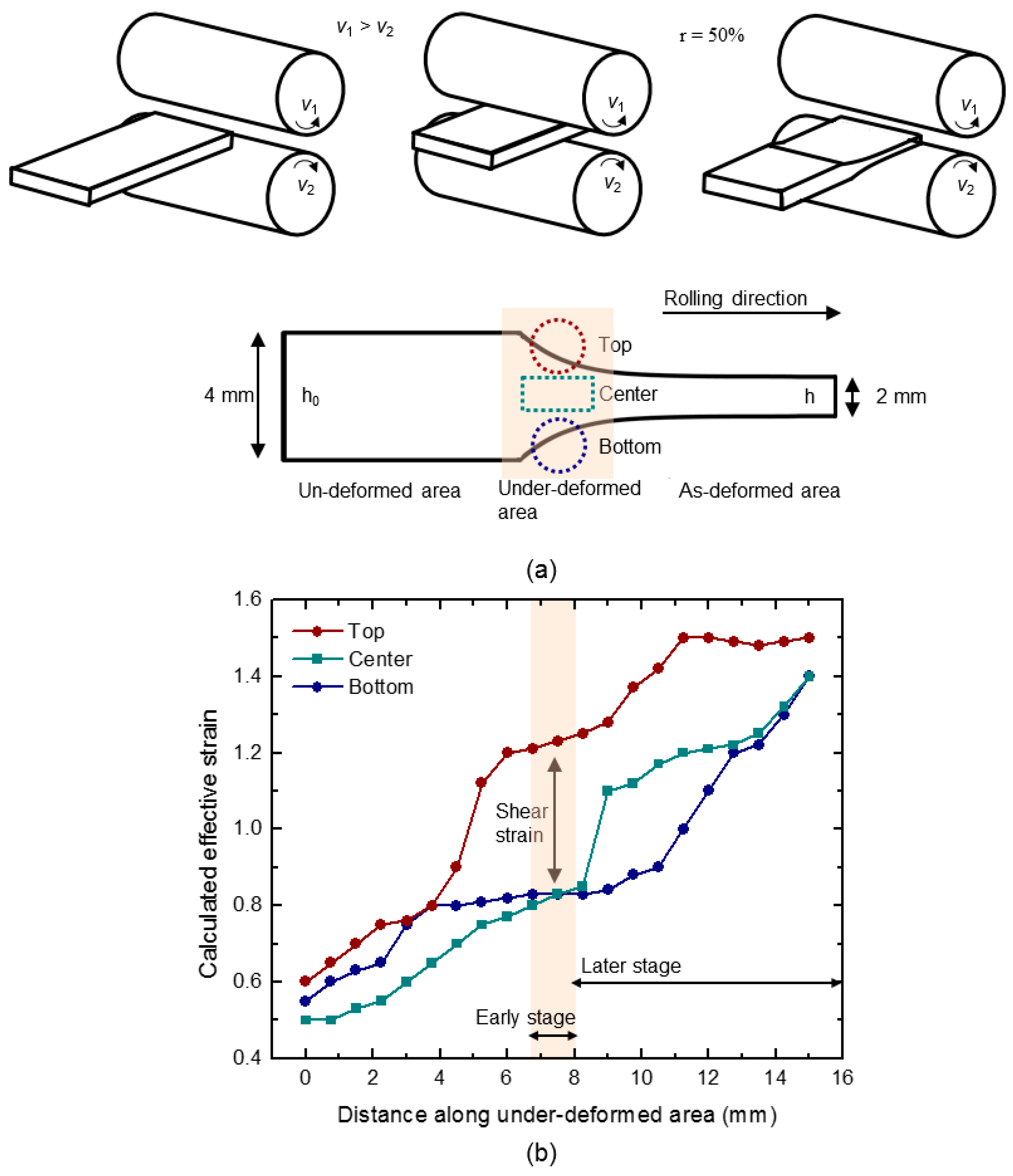
Figure 2.
Inversed pole figure (IPF) maps of the deformed sample in the (a) center and (c) top regions. Grain boundary (GB) maps of the deformed sample in the (b) center and (d) top regions at the early stage of AR deformation. The interfaces with black and blue colors represent grain and twin boundaries, respectively.

Figure 3.
(a) Intensity distribution of twinned grains with respect to various positions of c-axis from normal direction (ND) of the deformed sample and (b) boundaries’ misorientation distributions in the center and surface regions of the deformed sample.
Figure 3.
(a) Intensity distribution of twinned grains with respect to various positions of c-axis from normal direction (ND) of the deformed sample and (b) boundaries’ misorientation distributions in the center and surface regions of the deformed sample.
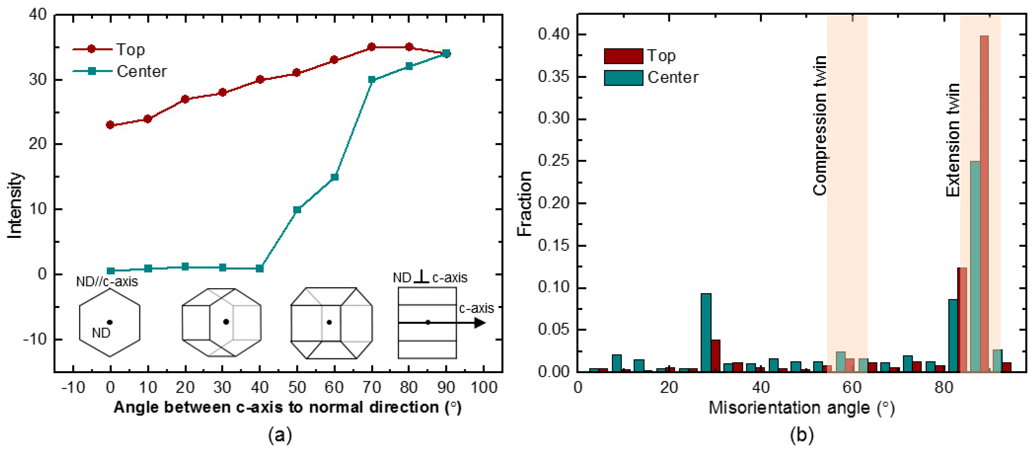
Figure 4.
EBSD-IPF maps of the deformed sample in the (a) center and (c) top regions. EBSD-GB maps of the deformed sample in the (b) center and (d) top regions at the late stage of AR deformation. The interfaces with black and blue colors represent grain and twin boundaries, respectively.
Figure 4.
EBSD-IPF maps of the deformed sample in the (a) center and (c) top regions. EBSD-GB maps of the deformed sample in the (b) center and (d) top regions at the late stage of AR deformation. The interfaces with black and blue colors represent grain and twin boundaries, respectively.
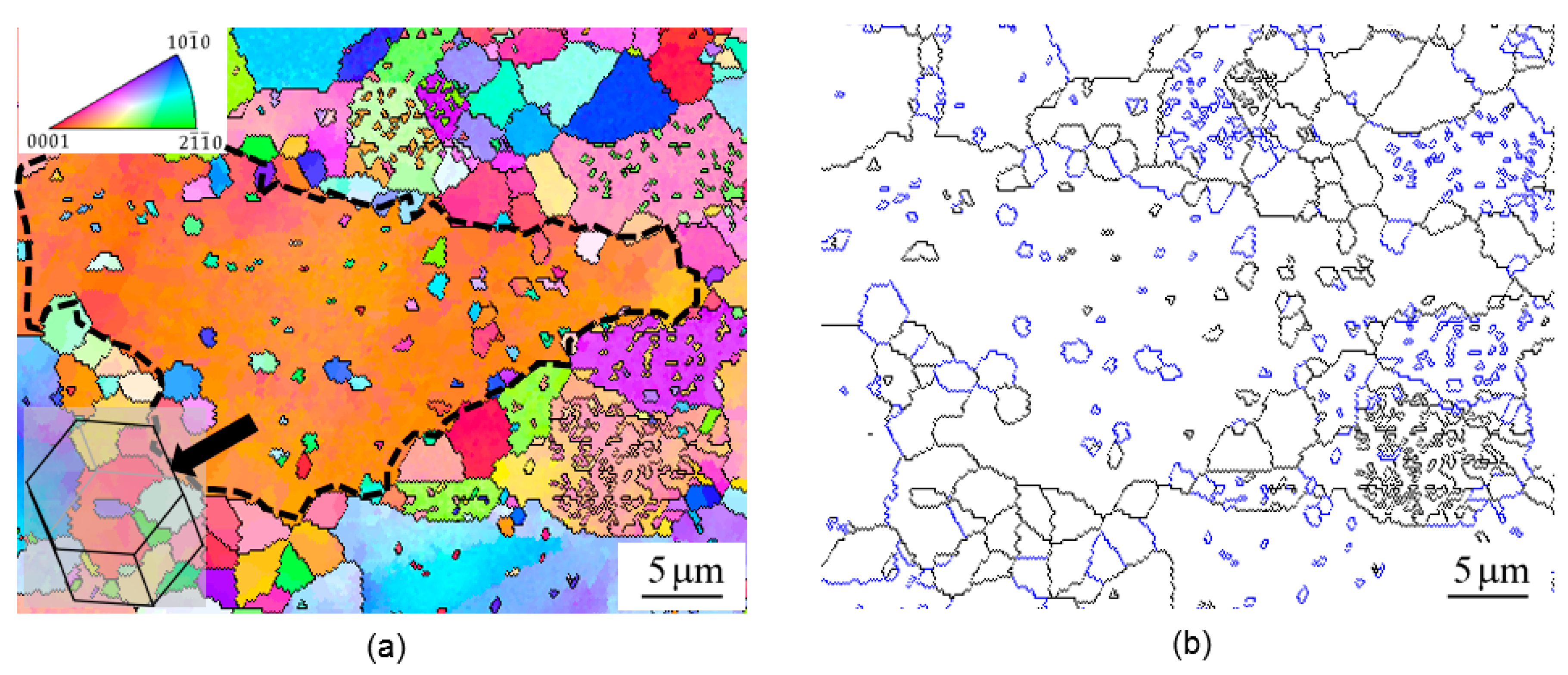

Figure 5.
(a) Misorientation distribution of boundaries and (b) size distribution of grains in the center and top regions at the late stage of AR deformation.
Figure 5.
(a) Misorientation distribution of boundaries and (b) size distribution of grains in the center and top regions at the late stage of AR deformation.

© 2018 by the authors. Licensee MDPI, Basel, Switzerland. This article is an open access article distributed under the terms and conditions of the Creative Commons Attribution (CC BY) license (http://creativecommons.org/licenses/by/4.0/).
Share and Cite
MDPI and ACS Style
Widiantara, I.P.; Yang, H.W.; Kamil, M.P.; Yoon, D.K.; Ko, Y.G. Grain Refinement by Extension Twin in Mg Alloy during Asymmetrical Rolling. Metals 2018, 8, 891. https://doi.org/10.3390/met8110891
AMA Style
Widiantara IP, Yang HW, Kamil MP, Yoon DK, Ko YG. Grain Refinement by Extension Twin in Mg Alloy during Asymmetrical Rolling. Metals. 2018; 8(11):891. https://doi.org/10.3390/met8110891
Chicago/Turabian StyleWidiantara, I Putu, Hae Woong Yang, Muhammad Prisla Kamil, Dong Keun Yoon, and Young Gun Ko. 2018. "Grain Refinement by Extension Twin in Mg Alloy during Asymmetrical Rolling" Metals 8, no. 11: 891. https://doi.org/10.3390/met8110891
Note that from the first issue of 2016, this journal uses article numbers instead of page numbers. See further details here.