Article

A Study on the Machining Characteristics of Curved Workpiece Using Laser-Assisted Milling with Different Tool Paths in Inconel 718

Department of Mechanical Design and Manufacturing Engineering, School of Mechanical Engineering, Changwon National University, 20 Changwondaehak-ro, Uichang-gu, Changwon-si, Gyeongsangnam-do 51140, Korea
*
Author to whom correspondence should be addressed.
Metals 2018, 8(11), 968; https://doi.org/10.3390/met8110968
Submission received: 29 October 2018 / Revised: 14 November 2018 / Accepted: 17 November 2018 / Published: 20 November 2018
(This article belongs to the Special Issue Machining and Finishing of Nickel and Titanium Alloys)

Abstract

:
Difficult-to-cut materials are being increasingly used in many industries because of their superior properties, including high corrosion resistance, heat resistance and specific strength. However, these same properties make the materials difficult to machine using conventional machining techniques. Laser-assisted milling (LAM) is one of the effective method for machining difficult-to-cut materials. In laser-assisted milling, the machining occur after the workpiece is locally preheated using a laser heat source. Laser-assisted milling has been studied by many researchers on flat workpiece or micro end-milling. However, there is no research on the curved shape using laser assisted milling. This study investigated the use of laser-assisted milling to machine a three-dimensional curved shape workpiece based on NURBS (Non-uniform rational b-spline). A machining experiment was performed on Inconel 718 using different tool paths (ramping, contouring) under various machining conditions. Finite elements analysis was conducted to determine the depth of cut. Cutting force, specific cutting energy and surface roughness characteristics were measured, analyzed and compared for conventional and LAM machining. LAM significantly improved these machining characteristics, compared to conventional machining. There results can be applied to the laser-assisted milling of various three-dimensional shapes.

Graphical Abstract

1. Introduction

Nickel-based alloys and titanium alloy has high properties, so using increased many industrial fields such as precision machine, aerospace, engine, turbine blade, semiconductor. Difficult-to-cut materials are difficult to conventional machining, because they have high-temperature strength, high abrasion resistance, and corrosion resistance [1,2].
Inconel 718 is one of the nickel-based superalloy used mainly in the engine, blade of the aerospace industries [3]. For machining of the Inconel 718, minimum quantity lubrication method, cryogenic machining and thermally-assisted machining have been studied. Thermally-assisted machining is developed for machining of difficult-to-cut materials. Especially, laser-assisted machining (LAM) is one of most effective method in the thermally assisted machining. The machining surface is softened using laser heat source [4,5,6].
Ahn et al. [7] studied energy efficiency of specific cutting energy in laser-assisted machining. The specific cutting energy was represented by tangential force and material removal rate. Machining experiments conducted, compared to conventional process with laser assisted machining process. Kizaki et al. [8] studied laser-assisted machining of zirconia ceramics using a diamond bur. Grinding experiments were conducted to assess the effectiveness of the laser assisted machining. The results, revealed that the force and tool damage was reduced in the laser assisted machining. Bermingham et al. [9] studied the tool life and wear mechanisms with Ti-6Al-4V using laser assisted milling. Laser assisted milling process is compared against conventional machining (MQL, coolants) and LAM-MQL process. The results, LAM process are increased of adhesion, diffusion, attrition and notching wear. Woo and the present author [10] studied the machining characteristics of AISI 1045 and Inconel 718 with cylindrical shape workpiece in LAM. Analysis were up-cut and down-cut milling. As a result, down-cut milling performed better than up-cut milling in the case of Inconel 718 in LAM. Bucciarelli et al. [11] studied micro-milling experiments in dry, wet, and laser-assisted conditions. As a result, they analyzed surface morphology, burr, part feature depth, cutting forces and tool wear. Hedberg et al. [12] studied laser assisted milling of Ti-6Al-4V with the consideration of surface integrity. Kong et al. [13] studied K24 nickel based super alloy for cutting performance and coated tool wear mechanisms using laser-assisted milling. Bermingham et al. [14] proposed different tool path strategies for laser-assisted milling. Xi et al. [15] studied numerical modeling used SPH method with beta titanium alloy in laser assisted machining. Kang and the present author [16] studied constitutive equation of ceramic in laser-assisted milling process. Ravindra et al. [17] studied high-pressure phase transformation and ductile material removal with silicon nitride using micro-laser assisted machining. Kim and the present author [18] studied machining characteristics of spherical shape using laser-assisted contouring and ramping machining. Ding et al. [19] studied thermal and mechanical modeling analysis of laser-assisted micro-milling of difficult-to-machine alloys. Lehtinen et al. [20] studied the effect of applying local heating by laser irradiation from bottom side of the metal sheet is investigated with a single point incremental forming approach. Kim and the present author [21] studied machining characteristics of AISI 1045 and Inconel 718 for an ellipsoidal shaped using laser assisted machining. Laser-assisted machining has been studied by many researchers on flat workpiece or micro end-milling. However, there is no research on the curved shape using laser assisted milling.
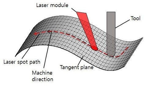
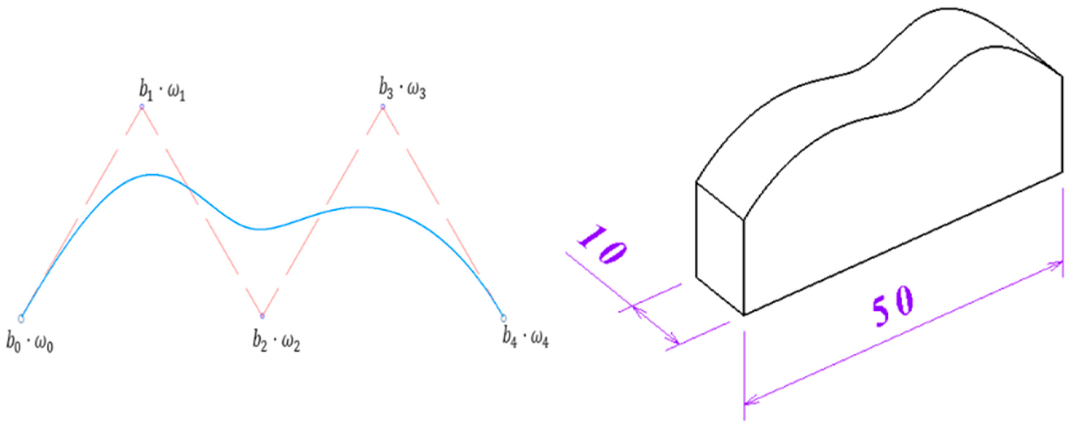
The aim of this study is evaluation of machinability with NURBS (Non-uniform rational b-spline) based of curved workpiece for three dimension machining in laser-assisted milling.
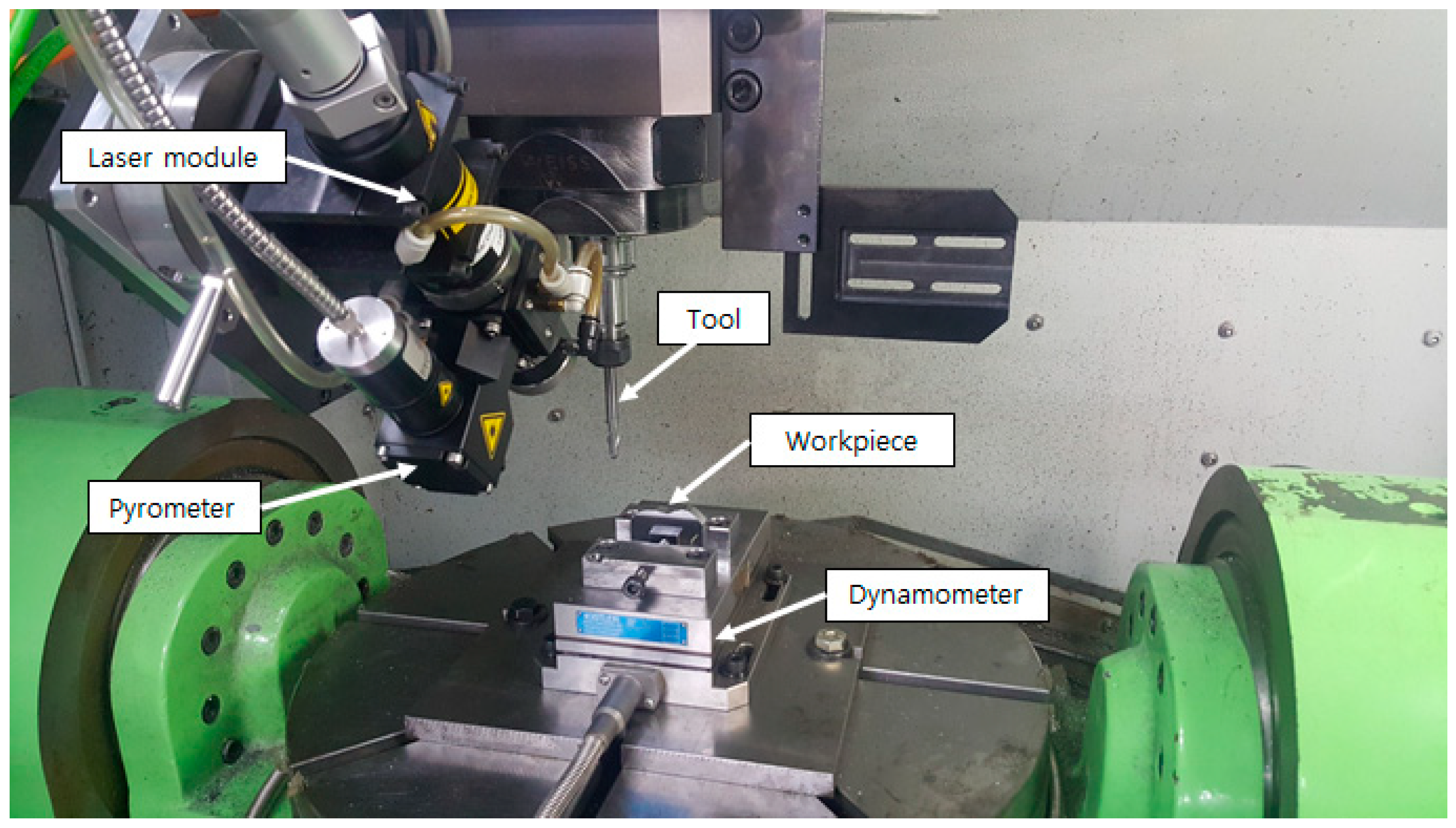
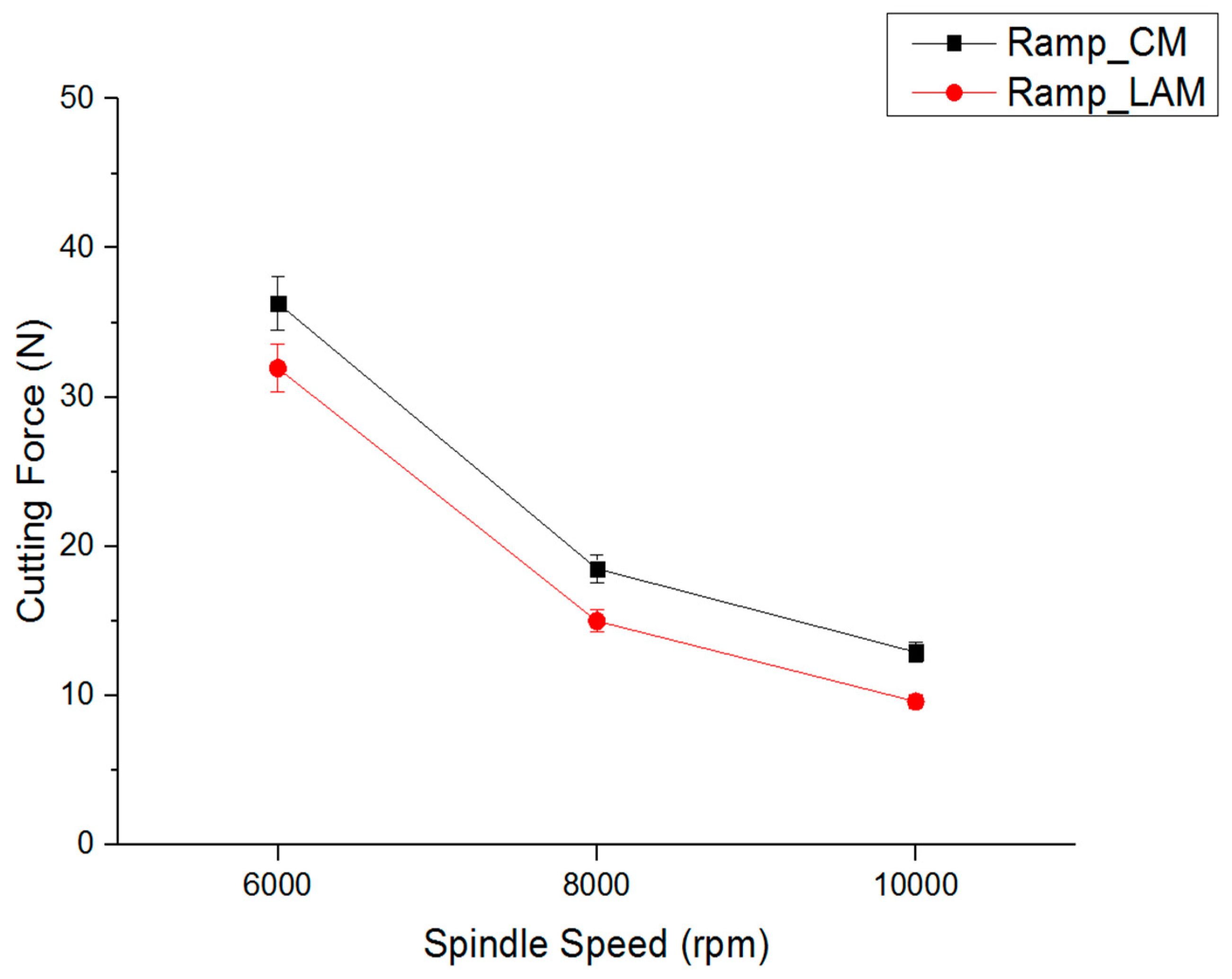
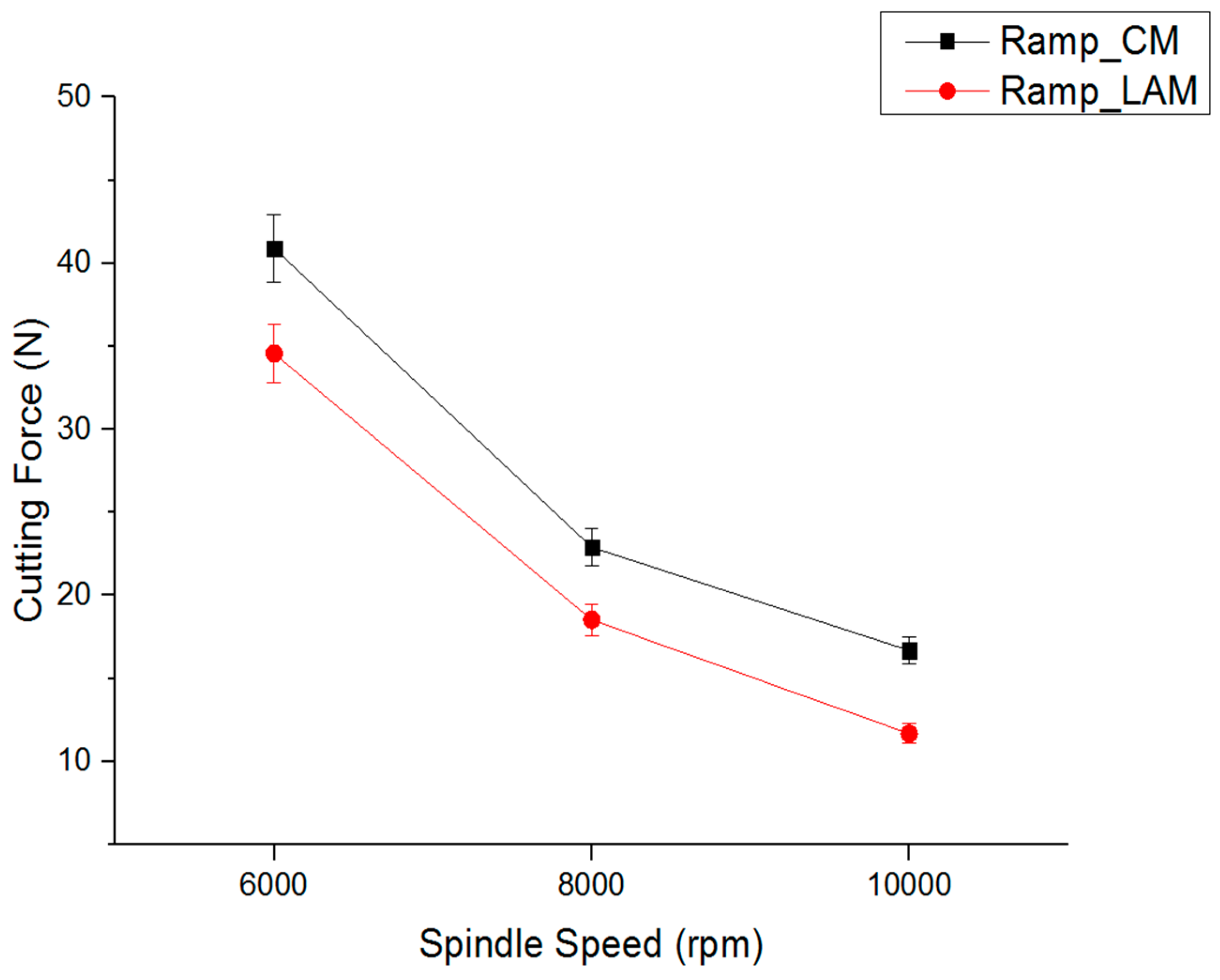
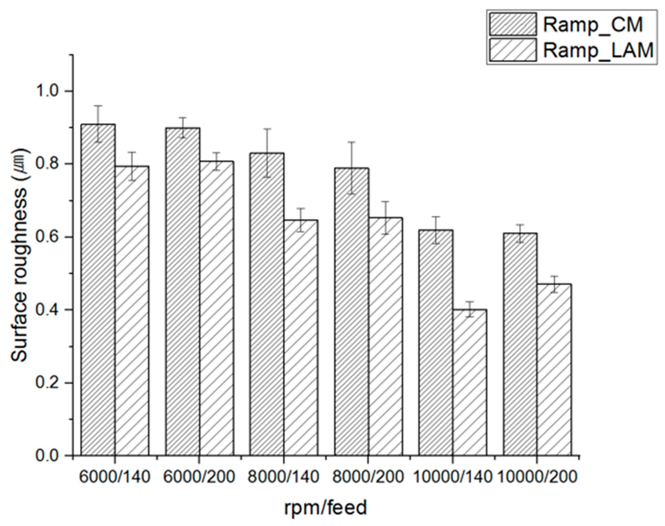
Thermal analysis was carried out to determine the preheating temperature and effective depth of cut. Thermal analysis was resorted to FEM simulation. Machining experiments of Inconel 718 with laser-assisted machining is used in different tool path, different spindle speed, and feed combinations. Contour milling was analyzed during up and down milling of the tool path on both the concave and convex surfaces. Ramp milling was analyzed during upward and downward milling of tool on both the concave and convex surfaces. Experiment results of conventional machining were compared with laser-assisted machining, such as cutting force, specific cutting energy, and surface roughness. Figure 1 shows a schematic diagram of curved shape machining using laser assisted machining.

2. Machining Methods

2.1. Contour Milling

During contour milling, the machining direction has to change in each region in order to maintain contact and continue milling. In the contour milling method, two types of milling operation are performed based on the orientation of the surface. These are designated up and down milling. These operations determine the relationship between the tool rotation direction and machining direction. In up milling, the tool rotates clockwise while the workpiece is moved from right to left. Down milling is the opposite of up milling. In the up milling process, the cutter rotates against the machining direction and the cutting chips are carried upward by the cutter. In the down milling process, the machining direction is the opposite, and the cutting chips are carried downward by the cutter. When machining a surface down milling is commonly used because down milling produces a better workpiece. Figure 2 shows a schematic diagram of contour milling method.

2.2. Ramp Milling

In the ramp milling method, milling is performed upward and downward based on the orientation of the surface. The important parameter that most affects the quality of the machining process during ramping down is the skidding of the tool on the surface. During the upward milling, only the front sides of the ball end mill are cutting the workpiece. And with down milling, only the back sides of the ball end mill contact the workpiece.
Figure 3 shows a schematic diagram of ramp milling method. Also, in ramp milling with LAM, it is necessary to control the laser heat source because changing the machining direction from the +X direction to the −X direction requires that the laser heat source also be changed in the same direction. To resolve this issue, an additional axis module was equipped on the spindle. The additional axis is the U axis corresponding to the X axis and V axis corresponding to the Y axis. It can be controlled by NC code in conjunction with NC code. In this study, when the direction of the X axis was changed, the U axis was moved in advance to control the laser heat source. Figure 4 shows additional axes of on the laser module. Figure 5 shows laser heat source moving method in ramp milling method.

2.3. Mechanical Model

The Figure 6 shows the NURBS curve and mechanical model. The basic form of the NURBS curve is the same as the basic form of a B-spline, with weights added to the B-spline. In general, an n-th NURBS curve with m unit sections is determined by control points ( b i ), weight ( ω i ), and knot vectors ( δ i ). The n-th NURBS curve is determined by Equation (1).
r ( u ) = i = 0 n B i ( u ) ω i b i i = 0 n B i ( u ) ω i
The third NURBS curve with m unit sections has (m + 3) adjustment points, (m + 3) weight, and (m + 4) knot vectors. The B i is the basis function of the B-spline. Where the role of the weight is to pull the curve toward the adjustment point and change the curve. In this study, the shape of the third NURBS curve is weight 2 in ω 1 and ω 2 and the other weight is 1. The length and thickness of the mechanical model are 50 mm and 10 mm, respectively [22].

3. Finite Element Analysis

3.1. Thermal Analysis

In generally, use of material data in models for finite element analysis typically requires that the results be presented in terms of effective true stress and strain. Several models are used for the finite element code. The Johnson–Cook constitutive model is the standard for analyzing high-rate deformation of materials. A Johnson–Cook constitutive model is described by Equation (2) as
σ y = ( A + B ε p n ) ( 1 + C ln ε ˙ p ) ( 1 T ^ m ) , T ^ = T 298 T m e l t 298
where σ y ,   ε p ,   ε ˙ p ,   T ^ ,   T and T m e l t represent yield strength, effective plastic strain, plastic strain rate (normalized by a rate 1.0 s−1), homologous temperature, room temperature and melting temperature, respectively. The first term of this constitutive model is strain hardening, the second term is the increase in strength with increased strain rate and the third term is softening due to heating. Table 1 shows Johnson–Cook parameter for Inconel 718 [23].
A thermal analysis was conducted to determine the preheating temperature and effective depth of cut prior to the experiments with laser-assisted machining.
A thermal analysis using temperature-dependent inputs is described by Equation (3) as
ρ c p δ T δ t = δ δ x ( k δ T δ x ) + δ δ y ( k δ T δ y ) + δ δ z ( k δ T δ z ) + Q ˙
where ρ ,   c p ,   k and Q ˙ represent density, specific heat, thermal conductivity and power generation per unit volume, respectively.
The initial condition at time t = 0 are given by Equation (4) as
T ( x , y , z , 0 ) = T 0
The boundary condition can be defined by Equation (5) as
k δ T δ z = q ( x , y ) h ( T T 0 )
where q, h, T and T 0 represent heat flux, heat transfer coefficient, surface temperature and ambient temperature, respectively. A thermal analysis was carried out to determine the workpiece surface temperature. The thermal conductivity and specific heat of Inconel 718 based on the temperature are shown in Figure 7.
The transient thermal analysis was performed by the finite element analysis software ANSYS Workbench (v18). A hexagonal-dominant mesh and tetrahedron mesh were applied in the FEM model. The tetrahedron mesh has a large degree of freedom and allows the creation of mesh in complex shapes. But tetra mesh has a risk of shape distortion. The shape distortion problem can be solved by using hexagonal mesh and creating a very dense mesh. So, the mesh size selected was 0.5 mm on the laser heat source for the contour milling and ramp milling, respectively. The analysis model of contour milling for Inconel 718 included 99,941 nodes and 31,984 elements. The analysis model of ramp milling for Inconel 718 included 178,748 nodes and 56,789 elements. Time increment was selected 32 s in the ramp milling and 65 s in the contour milling. Figure 8 shows the finite element analysis models. Table 2 and Table 3 shows the chemical compositions and mechanical properties in Inconel 718.

3.2. Thermal Analysis Results

Using the FEM analysis, the results for preheating temperature and depth of cut of Inconel 718 were obtained. Figure 9 shows the tensile strength of Inconel 718 according to temperature [24]. According to the results of FEM analysis, the preheating temperature was 938.87 °C in contour milling and 928.7 °C in ramp milling. The preheating temperature and the laser power was determined to be 940 °C and 100 W. This is because a temperature of about 940 °C suitable for reducing the residual stress caused by the heating of Inconel 718 as shown in Figure 10. Consequently, in the contour and ramp milling, the preheating temperature was determined to be 940 °C and the effective depth of cut was determined to be 0.25 mm.
Table 4 shows the maximum temperature of Inconel 718 for each laser power level both contour milling and ramp milling.

4. Experimental Set-Up

Experiments were performed on a 5-axis machining center (Hyundai-WIA Inc., Changwon, Korea, Hi-V560M). The laser equipment was installed in a 5-axis machine. A high power diode laser with a 1 kW power, wavelength of 920~980 nm (Laserline GmbH., Mulheim-Karlich, Germany, LDM 1000–100), was used for the laser heat source. A pyrometer was used to measure preheating temperature of the surface in real time (Dr. Mergenthaler GmbH., Neu-Ulm, Germany, LPC 03). The cutting force was measured by using dynamometer and amplifier (KISTLER Co., Ltd., Winterthur, Switzerland, 9257B, 5019). The surface roughness was measured by using surface measurement system (OPTACOM GmbH & Co., Grettstadt, Germany, KG., VC-10). For the experiments, a 2-flute carbide ball end-mill with a diameter 8 mm (WIDIN Co., Ltd., Changwon, Korea, type DB512080) was used. For the experiment, different tool path techniques for ramp, and contour milling were conducted on a curved shape workpiece. Table 5 and Figure 11 show the experimental set-up.
In the curved shape, the laser heat source changes from an elliptical shape to a circular shape according to the curved surface. The shape of the laser heat source is changed to an elliptical shape the energy density is decreased, and the decreased energy density is used as input energy of the analysis.
There are two methods of controlling the temperature in laser assisted machining. One of them is the power control method, and the other one is the temperature control method. Both methods are control temperature using pyrometer. The power control method is a method of maintain the laser power constant from any place, the temperature control method is a method of maintain the temperature of the surface constant from any place. In this study, the power control method was used.
And, all experiments were repeated three times and the mean values of cutting force, specific cutting energy and surface roughness were measured. The machining conditions were recommended by cutting tool manufacturer (WIDIN Co., Ltd., Changwon, Korea), and various spindle speeds and feed rates are applied to analyze the effect of spindle speed and feed rate in the conventional machining (CM) and LAM. Figure 12 shows change of laser heat source according to curved shape. Table 6 shows experimental condition for LAM.

5. Results

5.1. Cutting Force

5.1.1. Contour Milling Method

The machining experiment was carried out by applying two methods, conventional machining and LAM. The contour milling method of experiment results are shown in Figure 13 and Figure 14. The spindle speed was 6000 rpm, 8000 rpm, and 10,000 rpm at feed rate 140 mm/min, the cutting force was reduced by 25.1%, 32.8%, and 39.6%, respectively, compare to CM. The spindle speed was 6000 rpm, 8000 rpm and 10,000 rpm at feed rate 200 mm/min, the cutting force was reduced by 15.5%, 27.1%, and 32.2%. At spindle speed of 10,000 rpm, the cutting force was decreased by the greatest extent. In totally, the cutting force was decreased as the spindle speed increased. For LAM, the preheating effect is highest when the feed rate 140 mm/min.

5.1.2. Ramp Milling Method

The ramp milling machining experiment was carried out by applying conventional machining and LAM under various machining conditions. The ramp milling method of experiment results shown in Figure 15 and Figure 16. The spindle speed was 6000 rpm, 8000 rpm, and 10,000 rpm at feed rate 140 mm/min, the cutting force was reduced by 12.1%, 19.18%, and 25.6%, respectively, compare to CM. The spindle speed was 6000 rpm, 8000 rpm and 10,000 rpm at feed rate 200 mm/min, the cutting force was reduced by 15.5%, 19.8% and 33.7%, respectively, compared to CM. At spindle speed of 10,000 rpm, the cutting force was decreased by the greatest extent. In totally, the cutting force was decreased as the spindle speed increased.

5.2. Specific Cutting Energy

The specific cutting energy (SCE) is an important parameter to evaluate the efficiency of a machining process. And it is the energy consumed in material removal rate per volume. In this study, was used to verify LAM efficiency with contour milling and ramp milling. The SCE was expressed in terms of material removal rate (MRR), cutting force (F) and cutting speed (V). The equations used in the calculation is as follows, Equation (6):
Specific   cutting   energy = F × V M R R   [ N / mm 2 ]
Figure 17 shows the specific cutting energy of contour milling and ramp milling during various the spindle speed in the LAM. When compared were contour milling and ramp milling in the machining of Inconel 718, the spindle speed and feed rate was increased the SCE decreased rate was dropped. Totally, the SCE of contour milling was lower than ramp milling. The decrease rate of SCE was highest by 49.91% at the spindle speed 6000 rpm and at the feed rate 140 mm/min.

5.3. Surface Roughness

Surface roughness is measured by a shape measuring machine. For the two machining methods, it was found that lower the feed rates resulted in better surface roughness. When the conventional machining results were compared and LAM. The spindle speed was 6000 rpm, 8000 rpm and 10,000 rpm at feed rate 140 mm/min, the surface roughness was reduced by 20.8%, 15.71%, and 29.33%, respectively, in the contour milling. At feed rate 200 mm/min, the surface roughness was reduced by 25%, 38.59%, and 31.14%, respectively, in the contour milling. In the ramp milling, at feed rate 140 mm/min, the surface roughness was reduced by 11.11%, 13.18%, and 17.34%, respectively. At feed rate 200 mm/min, the surface roughness was reduced by 22.89%, 22.95%, and 35.4%, respectively. Figure 18 shows the measured surface roughness results in contour milling method. Surface roughness was also better with a lower feed rate and a higher spindle speed for the contour milling method. Figure 19 shows measured surface roughness results in ramp milling method. At the feed rate 200 mm/min and at the spindle speed 8000 rpm, the decrease rate of surface roughness was highest by 38.59%.

6. Conclusions

In this study, laser assisted machining was carried out on a curved workpiece using two surface machining methods, contour and ramp milling. The findings of this study, the following conclusion are:
(1) Before the machining experiment, a thermal analysis was performed to determine the effective depth of cut. The preheating temperature was determined to be 940 °C and depth of cut was 0.25 mm at the laser power 100 W in the LAM. Machining experiment was performed the preheating temperature 940 °C and by attaching additional axes to the 5-axis machining center for efficient curved surface preheating.
(2) The machining experiments results were showed that improved the cutting force, specific cutting energy and surface roughness in the LAM. The reason for improvement of machinability in the LAM, due to the materials was softened by laser heat source, the decreased in vibration of cutting tool in the machining.
(3) The cutting force during contour milling was decreased by up to 39.6% using LAM, and during ramp milling was decreased by up to 33.7%. And better surface roughness was achieved with contour milling than with ramp milling. In both methods, when the feed rate is lower and the spindle speed is higher, surface roughness is improved. It is considered that the effect of decreasing the cutting force and surface roughness was decreased due to the bending of the tool in the ramp milling. And machining area of contour milling is smaller than ramp milling; the machinability is more improve in the contour milling.
(4) When the spindle speed was increased, the SCE was decreased in the ramp milling. At a feed rate 140 mm/min with ramp milling, decrease rate of SCE was biggest under the all machining conditions in LAM. There was no significant difference in SCE under all machining conditions by the contour milling. The SCE of the contour milling was lower than the ramp milling with all machining. This can be explanation by the preheating effect of contour milling was more effective than ramp milling in the LAM. Therefore, contour milling is recommended for curved workpiece machining with LAM.
(5) LAM was demonstrated to be superior in efficiency for machining Inconel 718 compared to CM. The analyses in this study can be used to develop guidelines for three-dimensional laser assisted machining. In conclusion, LAM was demonstrated to be one of the most effective TAM methods.

Author Contributions

E.J.K. designed and performed the experiments, analyzed the experiment results, writing the paper. C.M.L. supervised all of the work carried out this research.

Funding

This research was funded by the National Research Foundation of Korea (NRF), grant No. 2016R1A2A1A05005492 and The APC was funded by Brain Korea 21 plus project.

Acknowledgments

This research was supported by Basic Science Research Program through the National Research Foundation of Korea (NRF) funded by the Ministry of Science, ICT & Future Planning (No. 2016R1A2A1A05005492).

Conflicts of Interest

The authors declare no conflict of interest. The founding sponsors had no role in the design of the study; in the collection analyses, or interpretation of data; in the writing of the manuscript; and in the decision to publish the results.

References

  1. Kim, D.H.; Lee, C.M. A study of cutting force and preheating-temperature prediction for laser-assisted milling of Inconel 718 and AISI 1045 steel. Int. J. Heat Mass Transf. 2014, 71, 264–274. [Google Scholar] [CrossRef]
  2. Artetxe, E.; González, H.; Calleja, A.; Valdivielso, A.F.; Polvorosa, R.; Lamikiz, A.; Lacalle, L.N.L. Optimised methodology for aircraft engine IBRs five-axis machining process. Int. J. Mechatron. Manuf. Syst. 2016, 9, 385–401. [Google Scholar] [CrossRef]
  3. Valdivielso, A.F.; Lacalle, L.N.L.; Urbikain, G.; Rodriguez, A. Detecting the key geometrical features and grades of carbide inserts for the turning of nickel-based alloys concerning surface integrity. J. Mech. Eng. Sci. 2015, 230, 3725–3742. [Google Scholar] [CrossRef]
  4. Cha, N.H.; Lee, C.M. A Study on Machining Characteristics of Silicon Nitride with Spline Members in Laser-Assisted Turn-Mill. Int. J. Precis. Eng. Manuf. 2015, 16, 2691–2697. [Google Scholar] [CrossRef]
  5. Lee, C.M.; Kim, D.H.; Back, J.T.; Kim, E.J. Laser assisted milling device: A review. Int. J. Precis. Eng. Manuf. Green Technol. 2016, 3, 199–208. [Google Scholar] [CrossRef]
  6. Jang, D.Y.; Jung, J.H.; Seok, J.W. Modeling and parameter optimization for cutting energy reduction in MQL milling process. Int. J. Precis. Eng. Manuf. Green Technol. 2016, 3, 5–12. [Google Scholar] [CrossRef]
  7. Ahn, J.W.; Woo, W.S.; Lee, C.M. A study on the energy efficiency of specific cutting energy in laser-assisted machining. Appl. Therm. Eng. 2016, 94, 748–753. [Google Scholar] [CrossRef]
  8. Kizaki, T.; Ito, Y.; Tanabe, S.; Kim, Y.J.; Sugita, N.; Misuishi, M. Laser-Assisted Machining of Zirconia Ceramics using a Diamond Bur. Procedia CIRP 2016, 42, 497–502. [Google Scholar] [CrossRef]
  9. Bermingham, M.J.; Sim, W.M.; Kent, D.; Gardiner, S.; Dargusch, M.S. Tool life and wear mechanisms in laser assisted milling Ti-6Al-4V. Wear 2015, 322, 151–163. [Google Scholar] [CrossRef]
  10. Woo, W.S.; Lee, C.M. A study of the machining characteristics of AISI 1045 steel and Inconel 718 with a cylindrical shape in laser-assisted milling. Appl. Therm. Eng. 2015, 91, 33–42. [Google Scholar] [CrossRef]
  11. Bucciarelli, A.; Kulia, P.D.; Melkote, S.M.; Fortunato, A. Micro-machinability of A-286 Steel with and without Laser Assist. Procedia CIRP 2016, 46, 432–435. [Google Scholar] [CrossRef]
  12. Hedberg, G.K.; Shin, Y.C. Laser-assisted milling of Ti-6Al-4V with the consideration of surface integrity. Int. J. Adv. Manuf. Technol. 2015, 79, 1645–1658. [Google Scholar] [CrossRef]
  13. Kong, X.J.; Yang, L.J.; Zhang, H.Z.; Zhou, K.; Wang, Y. Cutting performance and coated tool wear mechanisms in laser-assisted milling K24 nickel-based superalloy. Int. J. Adv. Manuf. Technol. 2015, 77, 2151–2163. [Google Scholar] [CrossRef]
  14. Bermingham, M.J.; Schaffarzyk, P.; Palanisamy, S.; Dargusch, M.S. Laser-assisted milling strategies with different cutting tool paths. Int. J. Adv. Manuf. Technol. 2014, 74, 1487–1494. [Google Scholar] [CrossRef]
  15. Xi, Y.; Zhan, H.Y.; Rashid, R.A.R.; Wang, G.; Sun, S.J.; Dragusch, M. Numerical modeling of laser assisted machining of a beta titanium alloy. Comput. Mater. Sci. 2014, 92, 149–156. [Google Scholar] [CrossRef]
  16. Kang, D.W.; Lee, C.M. A study on the development of the laser-assisted milling process and a related constitutive equation for silicon nitride. CIRP Ann. Manuf. Technol. 2014, 63, 109–112. [Google Scholar] [CrossRef]
  17. Ravindra, D.; Ghantassla, M.K.; Patten, J. Ductile mode material removal and high-pressure phase transformation in silicon during micro-laser assisted machining. Precis. Eng. 2014, 36, 364–367. [Google Scholar] [CrossRef]
  18. Kim, I.W.; Lee, C.M. A study of the machining characteristics of specimens with spherical shape using laser-assisted milling. Appl. Therm. Eng. 2016, 100, 636–645. [Google Scholar] [CrossRef]
  19. Ding, H.T.; Shen, N.G.; Shin, Y.C. Thermal and mechanical modeling analysis of laser-assisted micro-milling of difficult-to-machine alloys. J. Mat. Proc. Technol. 2012, 212, 601–613. [Google Scholar] [CrossRef]
  20. Lehtinen, P.; Vaisanen, T.; Salmi, M. The effect of local heating by laser irradiation for aluminum, deep drawing steel and copper sheets in incremental sheet forming. Phys. Procedia 2015, 78, 312–319. [Google Scholar] [CrossRef]
  21. Kim, I.W.; Lee, C.M. Investigarion into the machining characteristics of AISI 1045 steel and Inconel 718 for an ellipsoidal shape using laser-assisted contouring and ramping machining. Int. J. Precis. Eng. Manuf. 2017, 18, 1231–1238. [Google Scholar] [CrossRef]
  22. Kim, E.J.; Lee, C.M. A Study on the preheating Method of NURBS Shaped Workpiece by Laser Assisted Machining. J. Korean Soc. Precis. Eng. 2016, 33, 101–107. [Google Scholar] [CrossRef]
  23. Kobayashi, T.; Simons, J.W.; Brown, C.S.; Schokey, D.A. Plastic flow behavior of Inconel 718 under dynamic shear loads. Int. J. Impact Eng. 2008, 35, 389–396. [Google Scholar] [CrossRef]
  24. Sun, S.; Brandt, M.; Dargusch, M.S. Thermally enhanced machining of hard-to-machine materials—A review. Int. J. Mach. Tools Manuf. 2010, 50, 663–680. [Google Scholar] [CrossRef]
Figure 1. Schematic diagram of the curved shape machining using laser assisted milling.
Metals 08 00968 g001
Figure 2. Schematic diagram of contour milling. (The sequence of tool paths are 1, 2, 3 and 4).
Metals 08 00968 g002
Figure 3. Schematic diagram of ramp milling. (The sequence of tool paths are 1, 2, 3 and 4).
Metals 08 00968 g003
Figure 4. Additional axes of laser module.
Metals 08 00968 g004
Figure 5. Laser heat source moving method in ramp milling. (1. During machining, the laser heat source is located in front of the tool, 2. After machining, the laser heat source is located behind of the tool, 3. During the machining direction is change, the laser heat source is moved using the additional axis of the laser module (U-axis moving), 4. During machining, the laser heat source is located in front of tool).
Metals 08 00968 g005
Figure 6. The NURBS (Non-uniform rational b-spline) curved and mechanical model.
Metals 08 00968 g006
Figure 7. Thermal conductivity and specific heat of Inconel 718 according to temperature.
Metals 08 00968 g007
Figure 8. Finite element analysis models of contour milling (a) and ramp milling (b).
Metals 08 00968 g008
Figure 9. Tensile strength of Inconel 718 according to temperature (reproduced from [24], with permission from ELSEVIER, 2010).
Metals 08 00968 g009
Figure 10. Analysis results of ramp milling (a) and contour milling (b) in the Inconel 718.
Metals 08 00968 g010
Figure 11. Experimental set-up.
Metals 08 00968 g011
Figure 12. Changes of laser heat source shape according to curved surface.
Metals 08 00968 g012
Figure 13. Experiment results by the feed rate 140 mm/min in contour milling.
Metals 08 00968 g013
Figure 14. Experiment results by the feed rate 200 mm/min in contour milling.
Metals 08 00968 g014
Figure 15. Experiment results by the feed rate 140 mm/min in ramp milling.
Metals 08 00968 g015
Figure 16. Experiment results by the feed rate 200 mm/min in ramp milling.
Metals 08 00968 g016
Figure 17. Specific cutting energy of feed rate at 140 mm/min (a) and feed rate at 200 mm/min (b) with LAM.
Metals 08 00968 g017
Figure 18. Surface roughness in the contour milling.
Metals 08 00968 g018
Figure 19. Surface roughness in the ramp milling.
Metals 08 00968 g019
Table 1. Johnson–Cook constitutive model parameters of the Inconel 718.
A (GPa)B (GPa)nmCTmelt (°C) ρ (kg m−3)Cv (kg °C−1)
0.981.370.1641.030.0213008190435
Table 2. Chemical compositions of the Inconel 718 (wt.%).
ElementCrNiAlNbTiCoMo
Content (%)0.790.450.550.250.0160.080.018
Table 3. Mechanical properties of the Inconel 718.
Yield Strength (MPa)Tensile Strength (MPa)Elongation (%)Hardness (HC)
98012801242
Table 4. Maximum temperature of Inconel 718 each laser power.
Laser Power (W)Contour (°C)Ramp (°C)
80814.35803.93
90877.06869.43
100938.87928.70
110997.60986.98
1201054.601044.00
Table 5. Specifications of the experimental set-up.
InstrumentCompanySpecification
MachineHyundai-WIAHi-V560M
Laser opticLaserlineLDM 1000-100
PyrometerDr. MergenthalerLPC03
DynamometerKistler9257B
AmplifierKistler5019
Table 6. Experimental conditions for laser-assisted milling (LAM).
ConditionInconel 718
Tool pathramp, contour
Spindle speed (rpm)6000, 8000, 10,000
Feed rate (mm/min)140, 200
Depth of cut (mm)0.25
ToolØ 8 Ball end mill, 2F, 100 L
Preheating temperature (°C)940
Laser heat source size (mm)3
Laser wavelength (nm)920–980
Laser power (W)100

