Thermodynamic of Liquid Iron Ore Reduction by Hydrogen Thermal Plasma

Department of Metallurgy, Montanuniversitaet Leoben, 8700 Leoben, Austria
*
Author to whom correspondence should be addressed.
Metals 2018, 8(12), 1051; https://doi.org/10.3390/met8121051
Submission received: 9 November 2018
/
Revised: 3 December 2018
/
Accepted: 4 December 2018
/
Published: 11 December 2018
(This article belongs to the Special Issue Ironmaking and Steelmaking)
Abstract
:The production of iron using hydrogen as a reducing agent is an alternative to conventional iron- and steel-making processes, with an associated decrease in CO2 emissions. Hydrogen plasma smelting reduction (HPSR) of iron ore is the process of using hydrogen in a plasma state to reduce iron oxides. A hydrogen plasma arc is generated between a hollow graphite electrode and liquid iron oxide. In the present study, the thermodynamics of hydrogen thermal plasma and the reduction of iron oxide using hydrogen at plasma temperatures were studied. Thermodynamics calculations show that hydrogen at high temperatures is atomized, ionized, or excited. The Gibbs free energy changes of iron oxide reductions indicate that activated hydrogen particles are stronger reducing agents than molecular hydrogen. Temperature is the main influencing parameter on the atomization and ionization degree of hydrogen particles. Therefore, to increase the hydrogen ionization degree and, consequently, increase of the reduction rate of iron ore particles, the reduction reactions should take place in the plasma arc zone due to the high temperature of the plasma arc in HPSR. Moreover, the solubility of hydrogen in slag and molten metal are studied and the sequence of hematite reduction reactions is presented.
1. Introduction
The average CO2 emissions from iron and steel industry is 1900 kg/ton liquid steel (tLS) [1]. The integrated blast furnace–basic oxygen furnace steelmaking route produces approximately 2120 kg CO2/tLS, whereas the integrated HYL3—Electric arc furnace rout produces 1125 kg CO2/tLS which is the minimum amount among the different steelmaking integrated routes [2]. The reduction of iron ores with hydrogen has been considered a future alternative process for CO2-free steelmaking [3,4,5,6,7,8]. However, existing studies have focused mainly on the reduction of iron ore in a solid state, and there are not many studies in the field of liquid iron ore reduction using hydrogen [9,10,11,12].
Laboratory facilities of hydrogen plasma smelting reduction (HPSR) are available at the laboratory of the Chair of Ferrous Metallurgy of Montanuniversitaet Leoben. Figure 1 shows the basic process flow sheet of the HPSR laboratory set up and the reactor layout. During this process, a mixture of iron ore with additives, mainly lime, is fed to the reactor through a hollow graphite electrode by a screw feeder. The gas used in this process can be pure hydrogen or a mixture of hydrogen and argon or hydrogen and nitrogen. Therefore, a mixture of hydrogen, argon or nitrogen, and iron ore are injected into the reactor. Hydrogen as a reducing agent plays the main role in the reduction process. Therefore, the hydrogen utilization degree defines process efficiency. According to the results of the previous studies [13,14,15] at the Chair of Ferrous metallurgy of Montanuniversitaet Leoben, the concentration of hydrogen in the gas mixture should be lowered to increase the hydrogen utilization. Hence, the flow rate of the gas mixture and the ratio of hydrogen to argon or nitrogen are the main influencing parameters on the process efficiency. In fact, there are two possible methods of iron ore reduction using hydrogen. The first is inflight reduction, which occurs from the tip of the electrode and the slag surface where iron ore and gas particles are at high temperatures. The second is the reduction of liquid iron oxide on the slag surface. Despite the iron oxide reduction by hydrogen, a small amount of iron oxide is reduced by carbon. Carbon can be entered into the melt from the graphite electrode and reduce iron oxide due to the high temperature of the electrode. The graphite electrode is eroded and the eroded particles are introduced into the melt.
The off gas contains Ar or N2, H2O, H2, CO, and CO2, which leaves the reactor from the off gas duct. In order to analyze the chemical composition of the off gas and, accordingly, calculate the hydrogen utilization degree, reduction rate, and reduction degree of iron oxide, a mass spectrometer was installed in the laboratory. Electricity power was supplied by a DC power supply with a power maximum of 8 kW. All sections of the plasma reactor were cooled by a water-cooling system. To monitor the arc, an optical spectrometer with a fiber was used to monitor the arc.
2. Thermodynamic Properties of Thermal Plasma
In HPSR, the gas particles are ionized by the generation of the plasma arc at the tip of the graphite electrode inside the HPSR plasma reactor [3,13,16]. The plasma arc can activate molecular hydrogen. Therefore, molecular ; atomic ; ionic hydrogen ; and excited state H* are present in the plasma arc zone [17]. Hence, the reduction reaction of hematite is represented by
Metal oxide and H2O–H2, H2O–H, and H2O–H+ lines over the temperature are presented by the Ellingham diagram, which provides an estimation of the possibility of metal oxide reduction by hydrogen in terms of thermodynamic characteristics. In this diagram, the H2O–H+ line lies below the other lines. Consequently, hydrogen in the ionized state can reduce not only the iron oxides but also all other metal oxides [18,19,20].
If the temperature of the particles in plasma (molecules, atoms, ions and electrons) are the same and each process is balanced with its revers process, the plasma is in complete thermodynamic equilibrium (CTE). Plasma can be divided into two different categories: thermal or equilibrium plasmas and cold or nonequilibrium plasmas. In thermal plasmas, the temperature of electrons and ions are equal. However, not only laboratory scale plasmas but also some of the natural plasmas cannot meet all conditions of CTE. In the center of an electric arc, the deviations from equilibrium occur, and then it is more probable to be in a local thermodynamic equilibrium (LTE) state. In HPSR, the particles that diffuse into the plasma arc zone have enough time to equilibrate or to be at the same temperature. Therefore, hydrogen arc plasma is a thermal plasma and it is under LTE conditions [21,22,23].
Robino et al. [16] represented the standard Gibbs free energy changes for different mole fractions of monoatomic hydrogen in a mixture of H and H2. The results show that by increasing the mole fraction of monoatomic hydrogen, the standard free energy markedly declines. Despite the low mole fraction of ionic hydrogen, its reduction ability is significantly high. In other words, monoatomic hydrogen (H) is able to reduce metal oxides more readily.
Zhang et al. [24] compared the Gibbs free energies changes for forming water by different hydrogen species as a function of temperature. Based on this, the reduction potentials are ordered as follows
Figure 2 shows the Gibbs free energy changes for reduction of Fe2O3, Fe3O4, and FeO by various hydrogen species over temperature, which were calculated using FactSage™ 7.1 (Database: FactPS 2017). It confirms the order of the reduction ability of hydrogen plasma species, which is in a good agreement with the Zhang et al. [24] diagram. This diagram also shows that when using hydrogen as a reducing agent, FeO is more stable than the other forms of iron oxides.
Consequently, to have a high reduction rate, the reduction reaction of iron oxides should occur with hydrogen-activated particles (i.e., atomized, ionized, and excited state of hydrogen particles). HPSR has been investigated extensively at Montanuniversitaet Leoben [3,4,13,14,15]. Badr [13] studied the characteristics of the HPSR process in terms of thermodynamics, kinetics, and the possibility of industrialization. His results have confirmed the observations of previous researchers [20,25,26].
According to the Saha equation, hydrogen molecules begin to dissociate when the temperature rises above 3000 K. The dissociation and ionization of 0.5 mol of hydrogen and 0.5 mol of argon at equilibrium were calculated by FactSage™ (Toronto, ON, Canada) 7.1 thermochemical software, and the results are shown in Figure 3. The results are in good agreement with Kahne et al. [27] and Lisal et al. [28] works. This figure indicates that dissociation and ionization are two separate processes. Above 5000 °C, hydrogen is completely dissociated and, above 15,000 °C, the ionization process is the dominant process.
In the HPSR process, hydrogen in the plasma zone at high temperatures is partially ionized which leads to create two different gases, light electrons, and heavy ions. and are the electron and heavy ion individual densities, respectively. Those densities can be used to define the ionization degree. The ionization degree is defined by the rates of ionization and recombination. Charge carriers in plasma are lost through the different processes. In HPSR, the main recombination processes are drift to the anode (liquid iron oxide), diffusion to the reactor refractories, and volume recombination. Some volume ionization and recombination processes of hydrogen are shown in Table 1 [29,30,31].
HPSR involves an equilibrium or thermal plasma (hot plasma) for which and a chemical equilibrium exists. Due to the collision frequency at high temperatures, the energy distribution is uniform among all particles. The mean kinetic energy of the ions can define the temperature of the ion particles. The kinetic energy or velocity of the individual particles is defined by the collisional processes. Therefore, the total mean kinetic energy is obtained by the summation of the energies of all particles [32].
Several species are present in the plasma zone of the HPSR process, namely photons, free electrons, hydrogen atoms, hydrogen ions, and molecules [17,33,34]. In the plasma arc, not only iron and iron oxide can be released from the iron ore and liquid bath but also carbon is released from graphite electrode. The amount of iron, iron oxide and carbon vapor depends on the process parameters [35]. Bohr’s model is used to describe the structure of hydrogen energy levels [32]. The collisional process, which is the dominant ionization process in the HPSR, gives rise to the atomization and ionization of the hydrogen and argon molecules [36]. Excitation occurs when a ground state electron of an atom or a molecule absorbs sufficient energy to transition to a higher energy level. Atoms or molecules in these states are known as excited state X*. The excited state lifetimes of hydrogen particles are between 10−8 and 10−6 s. Ionization is the process by which an atom or a molecule acquires sufficient energy to gain or lose an electron to form ions. The hydrogen ionization energy of an already excited particle (electron in the second orbit) is less than 13.6 eV, as given by Bohr’s theory,
where is the refinement of the ionization energy, is the ionization energy of the already excited particles, and n* is the quantum number in the excited state [32,37]. The collision cross-section is the effective area in which two particles must meet to scatter from each other. Since atoms do not have a well-defined size, Bohr derived a radius for atoms to calculate the cross-section, defined as
where n is the principal quantum number, r1 is the radius of the first Bohr orbit, and z is the atomic number. Therefore, the cross-section for atomic hydrogen is [32].
There are two types of collisions: elastic and inelastic. In an elastic collision, the atom absorbs a fraction of the electron initial momentum without any changes in its energy state. The probability of elastic collision depends on the equivalent cross-section, σ. For an inelastic collision, the degree of ionization is defined by the cross-section area, σ. According to the Maxwell–Boltzmann distribution function, the mean velocity of the particles depends on the square root of the temperature [23,38].
where m is the mass of the particles, K is the Boltzmann constant (), and T is the temperature of the particles. The density of the active particles, , in an electrically insulated surface and in the absence of an externally applied electric field is given by
where ni is the density of particles i. Combining Equations (5) and (6) gives the following formula, which is used for the calculation of the activated particles.
Therefore, with the increase of the temperature and the number density, the density of the activated particles will be increased.
3. Effect of Charge Polarity on the Iron Ore Reduction Reactions
A plasma-confining surface can be positively charged, negatively charged, or neutral. The density of the ions and electrons change while reaching a plasma-confining surface. In a typical thermal plasma, the thermal boundary layer is located near the surface. At the bottom of this layer, the plasma sheath is located. It was found that the plasma sheath is a narrow layer in which particles of opposite polarity are attracted and those with the same polarity are repelled [3,18,38].
The density gradients in the vicinity of the surface depend on the order of the Debye length. The layer near the surface with the charge imbalances is called the Debye sheath [23]. Plasma sheaths in the HPSR reactor are on refractory surfaces, on the liquid iron oxide surface, and on the graphite electrode surface. The thickness of the plasma sheath is defined by
where is the Debye length in m, is dielectric constant and equals 8.86 , e is electron charge and equals , and k is Boltzmann constant. The Debye length in thermal plasma is between to m [23]. The temperature of 25,000 K is the average temperature of the electrons in close vicinity to the liquid slag surface, and the electron density is . Thus, the Debye length on the slag surface in the plasma reactor is m. The thickness of the plasma sheath is approximately equal to the Debye length. However, the sheath edge, which is a collision-less transition layer between plasma and sheath, is between 1 and 10 Debye length [23,39]. The thickness of thermal boundary layer is several orders of magnitude larger than that of the plasma sheath. In the thermal boundary layer, recombination occurs, and the concentration of the excited particles decreases.
In HPSR, the reduction reactions of iron ore can take place during two different times: (1) inflight reduction of iron ore fines within the distance of the arc length and (2) the reduction on the surface of the liquid slag. Solid fine particles do not have any applied electrical field. However, a positive polarity is applied to the liquid slag. Therefore, the polarity of the slag surface is one of the main influencing parameters on the efficiency of the reduction process. Dembovsky [38] has described the effect of surface polarity on the thermodynamic variables in metallurgical reactions.
A surface where there is no applied electrical field (i.e., no net current flow) repels the electrons and absorbs positive ions. Because the electrons can first touch the surface due to their higher velocity, the surface is charged negatively. Consequently, positive ions are attracted to the surface, and the electrons are repelled by the negative surface in the plasma sheath. Therefore, the density of positive ions increases.
Figure 4 and Figure 5 show a schematic of active particles in a plasma state reaching positively and negatively charged reaction surfaces, respectively. When the surface is positively charged, the density of the electrons is higher than the density of the ions in the plasma sheath, and vice versa.
Considering the direct current straight polarity of the HPSR arc, ionized hydrogen atoms are repelled by the positive molten slag, leading to a decrease in the reduction rate of iron oxides. The effect of surface polarity on the Gibbs free energy changes for the reduction reaction of iron oxide using hydrogen at 10,000 K was represented by Dembovsky [38]. The pertinent reaction is given by
where x, y, and z are the molar fractions of molecular, atomic, and ionized hydrogen. Hydrogen is atomized and ionized at high temperatures. Therefore, the atomization and ionization degree of hydrogen and the polarity define the molar fractions of the particles reaching the reaction surface. Consequently, the reduction reaction rate depends on the molar fraction of particles reaching the surface [3,18,38]. Dembovsky [38] compared changes in the Gibbs free energy for the reduction of iron oxide at various polarities over temperature. He showed that when the surface polarity was negative, Gibbs free energy was more negative than the other cases. Therefore, the reduction reaction proceeds at a higher rate.
To assess the effect of the polarity on the reduction reaction of iron oxide, the Gibbs free energy changes of three reduction reactions were calculated by FactSage™ 7.1 (Database: FactPS 2017), and the results are shown in Figure 6.
If the positive polarity is used in the process, all ionized hydrogen particles cannot reach the reaction surface. Therefore, the Gibbs free energy is derived to increase and be more positive. In the case of the negative polarity, hydrogen positive ions can reach the reaction surface more readily. Therefore, the Gibbs free energy changes are more negative.
4. Ionization Degree of Hydrogen
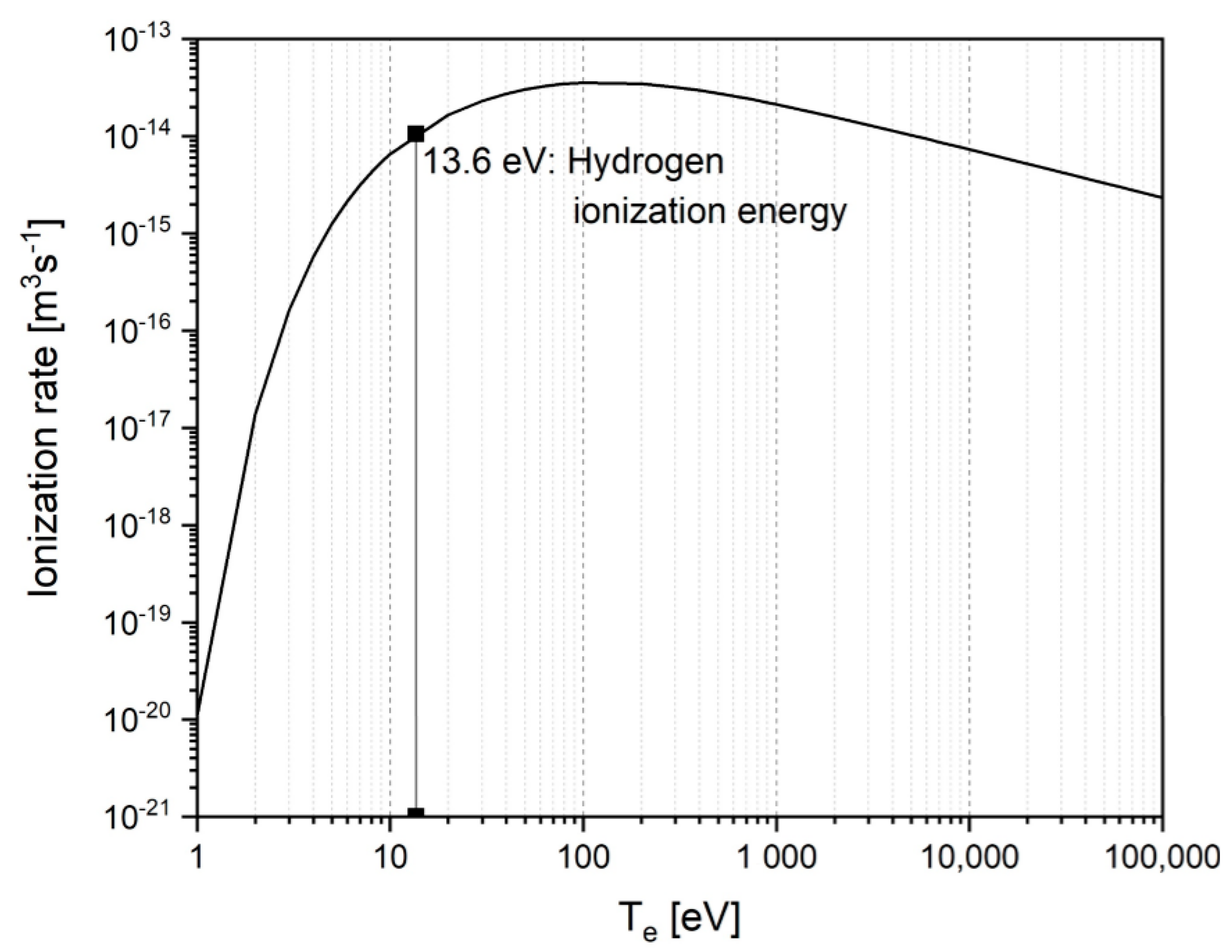
The collision of electrons with atoms leads to their ionization or excitation. To calculate the rate of production of the new electrons, the ionization collision frequency was multiplied by the electron density (ne) obtaining the so-called source rate (Se).
where and are the electron and neutral atom densities, respectively. σion is the cross-section for the electron-impact ionization and is the electron velocity [40,41]. The ionization rate 〈σionνe〉 of hydrogen atoms for the Maxwell distribution of electron temperature, , is shown in Figure 7. The maximum ionization rate is reached with energies above hydrogen ionization energy, which is 13.6 eV.
5. Solubility of Hydrogen
In the HPSR process, iron ore in the plasma reactor is melted and then continuously reduced by hydrogen. The density of slag is lower than the density of liquid iron. Therefore, there is expected to be a slag layer on the surface of the liquid metal during the reduction process. However, in the interface of arc and molten metal, where the reduction reactions take place, hydrogen species can reach the liquid iron surface and be absorbed. Hence, the study of the solubility of hydrogen in liquid iron is important.
Several researchers [40,42,43,44,45] have studied hydrogen solubility and the mechanism of hydrogen absorption in liquid iron. This study is important for steel makers as it explores the negative effects of hydrogen on the mechanical properties of steel. However, in HPSR, it is more important due to the existence of an enormous amount of hydrogen reaching liquid phases. In HPSR, hydrogen exists in molecular, atomic, and ionized forms. To be dissolved, hydrogen in a liquid iron should first be dissociated. The solubility of atomized hydrogen in liquid iron is defined by [46]
where is the equilibrium constant and is the hydrogen partial pressure. This equation is valid when hydrogen exists only in a molecular state. The solubility of hydrogen in a plasma state in liquid iron was presented by Dembovsky [42]. Badr [13] then revised the equation and represented by
where , , and are the partial pressures of atomized hydrogen, ionized hydrogen, and the electrons, respectively. and are the equilibrium constants for the dissolution of atomized and ionized hydrogen particles, respectively. Dembovsky [42] experimentally and theoretically showed that the solubility of gases in the plasma state in liquid iron are higher than the solubility of gases in the molecular state due to the lower activation energy for the dissolution of ionized and atomized particles.
During the operation of HPSR, a layer of slag covers the molten metal. Therefore, the slag can pick up hydrogen and water vapor, then transfer it to the liquid metal. Many studies [47,48,49,50] have been done to investigate the solubility of hydrogen in slags. Walsh et al. [43] studied the solubility of hydrogen in steelmaking slags. They reported that hydrogen is not dissolved in slag significantly when hydrogen gas is applied. Slags can dissolve small amount of hydrogen via the reaction between slag components and water vapor. They showed that water vapor in the molecular state is not dissolved in slags. Russell [51] studied the dissolution of the water vapor molecularly in molten glasses. He showed that water vapor is dissolved in molten glasses, however, he could not define the form of the dissolved hydrogen. Walsh et al. [29] reported that hydrogen solubility in acidic open hearth slags is less than that of basic slags, which agrees with Wahlster’s [52] work.
In HPSR, partial pressure of molecular hydrogen, atomic hydrogen, and ionized hydrogen define the solubility of hydrogen in liquid metal. Therefore, dissociation and ionization degree of hydrogen particles are important to take into account.
6. Mechanism of the Hematite Reduction Reaction in HPSR
To study the reduction of hematite using hydrogen at high temperatures, the equilibrium of Fe2O3 and H2 has been assessed by FactSage™ 7.1. For the assessment of the equilibrium, the range of the equilibrium temperature should first be determined. In HPSR, hematite is reduced by hydrogen. Hydrogen in the plasma arc zone is partially atomized and ionized. As what has already been discussed, the activated hydrogen species are stronger reducing agents than molecular hydrogen in reducing iron ore. The temperatures at the center of arc, at the vicinity of the arc, and on the liquid metal surface mainly depend on the amperage, voltage, arc length, and the gas composition. Murphy et al. [53] simulated the temperatures, velocities, and the vaporization of iron ore in the arc zone for a 150 A tungsten inert gas (TIG) welding arc. They showed that, with the use of helium, Fe is vaporized and the concentration of Fe can reach 7 mol % due to the high temperature of the weld pool, which is approximately 2773 °C. With the use of argon as a plasma gas, the temperature of the liquid metal at the interface and the Fe concentration are 2273 °C and 0.2%, respectively. The reason for this is that helium conducts heat better than argon. The temperature of the gas–liquid metal interface of HPSR is not yet defined. However, it seems to be much higher than the helium welding arc plasma not only because of the higher power of the electric supply but also the use of a high percentage of hydrogen in the gas mixture. Therefore, for the calculations of equilibrium, the temperature range between 1550 and 3000 °C was considered. The lower part of the range (i.e., 1550 °C) was considered in order to be above the melting temperature of pure iron, which is 1537 °C.
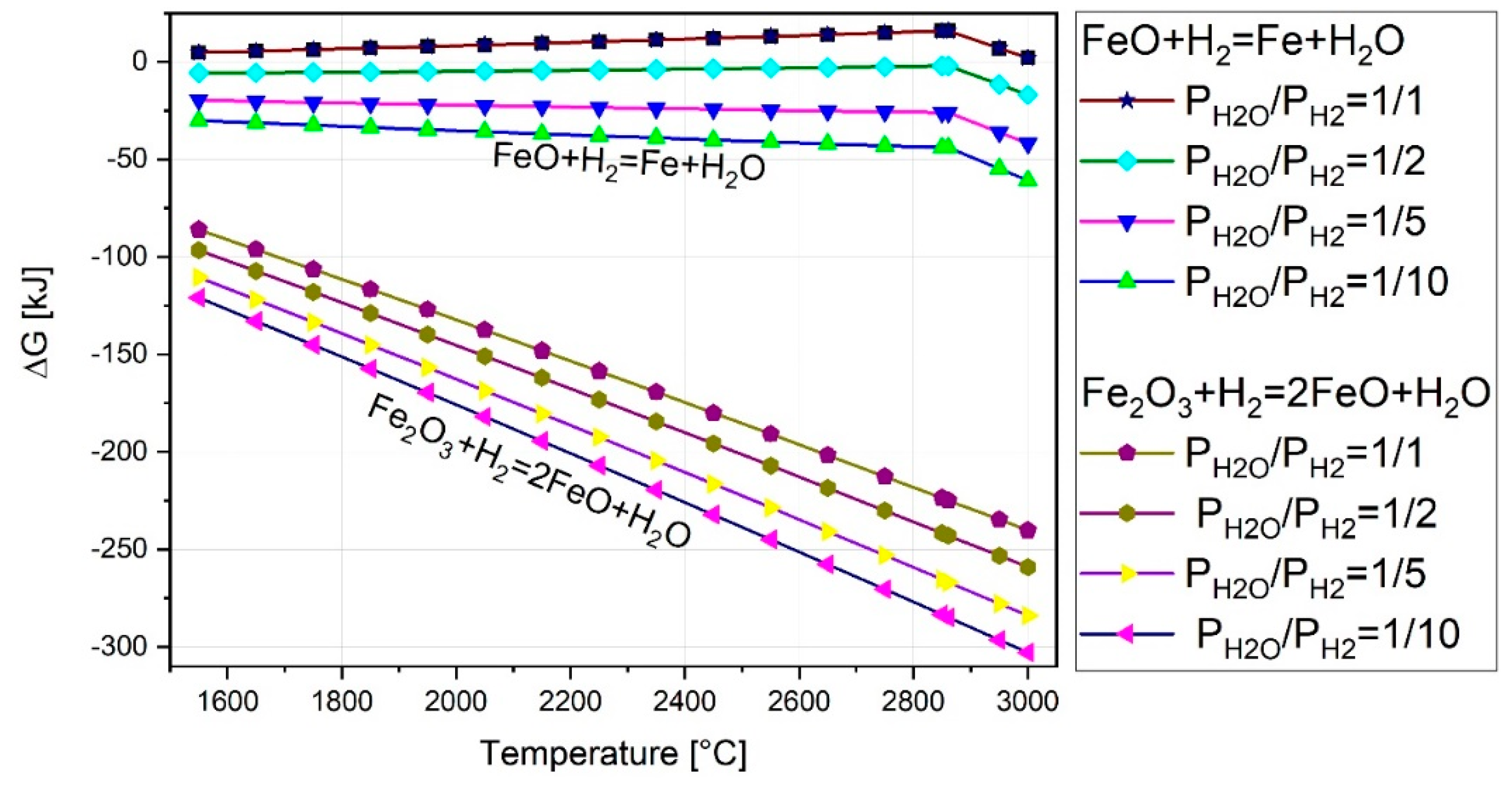
The reduction reactions of hematite using hydrogen occurs in two steps which are given by
This means that, at the first step of the reduction process, FeO is formed. Then, the reduction of wustite to form Fe by hydrogen takes place continuously during operation. To prove the reduction sequences, the Gibbs energy changes were calculated by FactSage™ 7.1 and the results are shown in Figure 8. The figure shows that the Gibbs energy changes of Equation (16) is more negative than that of Equation (17).
Figure 8 shows the Gibbs energy changes of the two reactions in four different pressure ratios of . The ratio of to was considered to be 1/1, 1/2, 1/5, and 1/10. The graph shows that, with the increase of water vapor partial pressure, the Gibbs free energy decreased due to the lack of hydrogen to reduce iron oxides. Consequently, at the first step, hematite is reduced to wustite, and then continuously reduced to Fe.
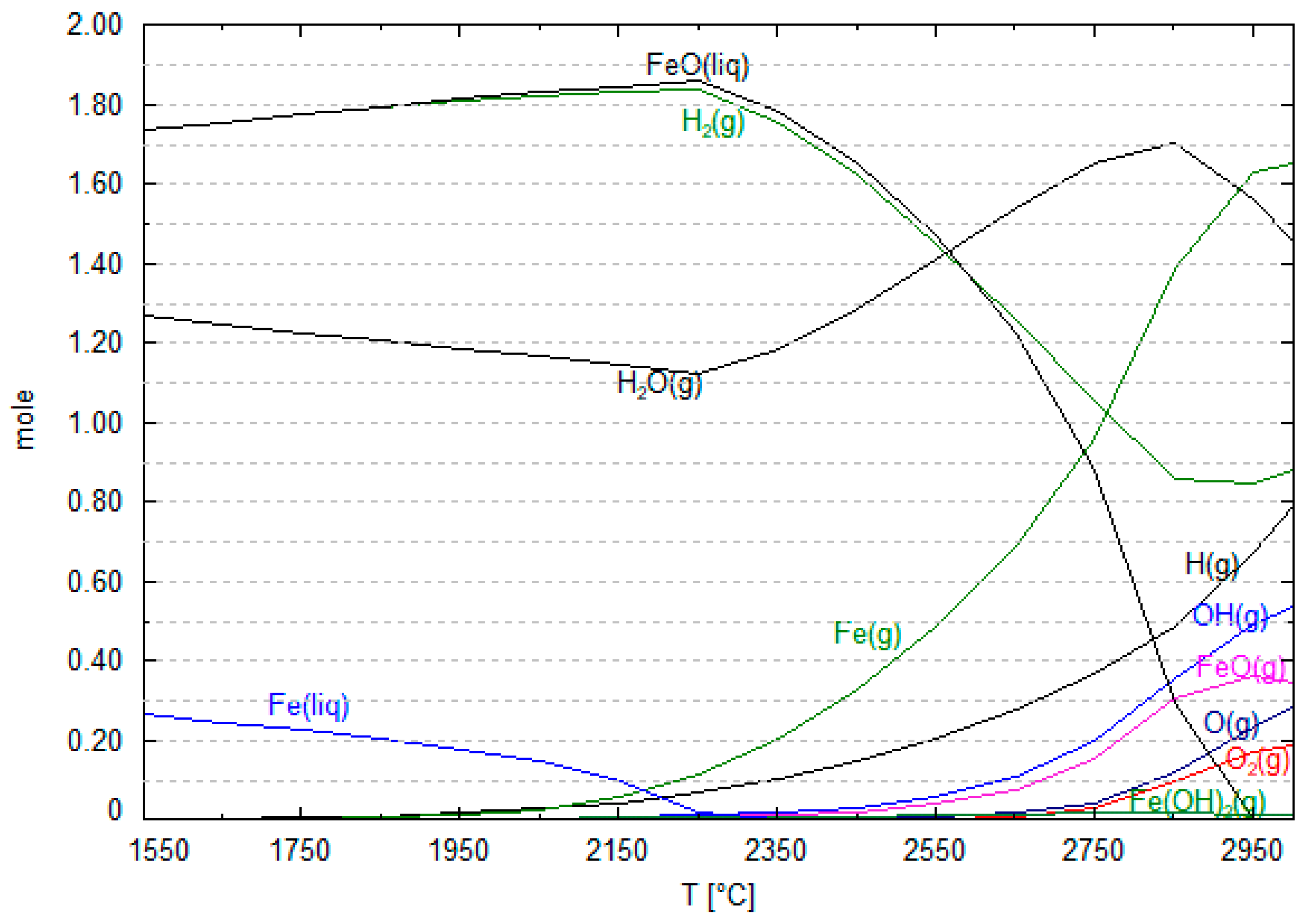
To reduce hematite using hydrogen 3 mol of hydrogen is required for each mole of hematite. Therefore, the pertinent equilibrium has been studied. Figure 9 shows the equilibrium of 1 mol of hematite and 3 mol molecular hydrogen. The results show that hydrogen utilization at equilibrium is 43% at the temperature of 1600 °C. The pertinent reduction reaction is given by
Therefore, the maximum hydrogen utilization degree using molecular hydrogen is 43%. However, it is expected to be higher when using hydrogen in a plasma state. In order to completely reduce FeO, further hydrogen should be injected into the reactore. Theoreticaly, regarding 43% hydrogen utilization degree, 2.34 mol of hydrogen is required to reach 100% of iron oxide reduction degree.
The complete reduction degree of hematite can be reached by 6.98 mol of hydrogen
Similar to the conventional steelmaking processes, FeO concentration in slag and its influence on the reduction rate should be taken into accont. With the decrease of FeO concentration in slag, the reduction rate and accordingly hydrogen utilization degree is decreased.
Kamiya et al. [26] studied the reduction of molten iron oxide using H2-Ar plasma. They reported that the hydrogen utilization degree can be 60% at low concentration of hydrogen in the gas mixture. Nagasaka et al. [54,55] studied the kinetics of molten iron oxide reduction using hydrogen. They compared the reduction rate of iron oxide with different reducing agent. They reported that the reduction rate of iron oxides using hydrogen is one or two orders of magnitude higher than those by other reductants.
The figure shows that, with the increase of the temperature, liquid iron begins to be vaporized and molecular hydrogen begins to be dissociated. H2O and Fe (liquid) decrease gradually with the increase of the temperature until 2268 °C, and FeO and H2 increase in the same rate. This means that the reduction rate is decreasing. The reason is that water vapor is dissociated, and H2, O2, and OH are formed. Consequently, Fe is oxidized by the produced O2. To prove this assumption, the equilibrium of 1 mol of H2O was calculated, and the results are presented in Figure 10.
Baykara et al. [56] produced hydrogen with water thermolysis process at the temperature of 2227 °C and a pressure of 1 atm. Mass and energy balance calculations were done to define the chemical composition of material of each stream. The chemical composition of dissociated water is shown in Table 2. Their results are in a good agreement with the present work which have been calculated theoretically.
The assessment of the water vapor equilibrium shows that it is dissociated and produces molecular oxygen and hydrogen. Therefore, the following reactions take place, respectively.
Consequently, the dissociation of water vapor at high temperatures causes a slight drop in the reduction rate of iron oxide.
To assess the reduction reaction of hematite with 3 mol of hydrogen, the hydrogen utilization degree was calculated at the temperature of 2750 °C, and the results are given by
The utilization degree of hydrogen can be calculated by the sum of the H2O and OH in the reaction. At this temperature, the hydrogen utilization degree is 58%.
In Figure 9, at the temperatures between 2268 and 2850 °C, Fe is vaporized. FeO is reduced to form Fe (g) and H2O. The amount of water vapor produced by the reduction reaction is more than that of released by the dissociation process. Hence, water vapor in this temperature range is increased. There is a peak for the H2O at the temperature around 2850 °C in Figure 9. Above this temperature, FeO (liquid) is going vanish, and the rate of the reduction decreases. Therefore, amount of molecular hydrogen is kept approximately constant and water vapor is decreased due to the dissociation process.
7. Summary and Conclusions
In summary, excited particles, such as electrons and ions, exist in a plasma arc. The reduction rate of iron oxide depends on the kind of hydrogen species present in the plasma state. It was shown that the reduction ability of each species is different and that the ionized hydrogen is the strongest reducing agent. The plasma arc temperature and particle density are the main parameters influencing the hydrogen ionization rate and, consequently, iron oxide reduction rate. At temperatures above 15,000 °C, most of the hydrogen and argon particles are in the ionized state, making the reduction of iron oxide more feasible. Regarding thermodynamic aspects, the Gibbs free energy changes were calculated for different iron oxide reduction reactions with different hydrogen species. It was found that the reduction ability of the hydrogen species is in the following order: . Moreover, the study of hematite and hydrogen at equilibrium shows that, at 1600 °C, hydrogen utilization is 43%. With the increase of the temperature above 1550 °C, water vapor dissociates. The highest reduction rate can be reached when the reduction reactions take place at the plasma arc zone, which is at high temperatures. Moreover, hydrogen positive ions can reach the liquid iron oxide easier with a negative polarity; therefore, the reduction rate of iron oxide could be increased.
Author Contributions
Conceptualization, M.N.S. and J.S.; methodology, M.N.S. and J.S.; software, M.N.S.; validation, M.N.S. and J.S.; formal analysis, M.N.S. and J.S.; investigation, M.N.S.; resources, M.N.S. and J.S.; writing (original draft preparation), M.N.S.; writing (review and editing), visualization, M.N.S. and J.S.; supervision, M.N.S. and J.S.
Funding
The SuSteel Project supported this research. The SuSteel project was funded by the Austrian Research Promotion Agency (FFG). Montanuniversitaet Leoben, K1–Met GmbH, voestalpine Stahl Donawitz GmbH, and voestalpine Stahl Linz GmbH are the partners of the SuSteel project.
Conflicts of Interest
The authors declare no conflict of interest.
References
- Kundak, M.; Lazic, L.; Crnko, J. CO2 Emissions in the Steel Industry; Croatian Metallurgical Society (CMS): Zagreb, Croatia, 2009. [Google Scholar]
- Lisienko, V.G.; Chesnokov, Y.N.; Lapteva, A.V.; Noskov, V.Y. Types of greenhouse gas emissions in the production of cast iron and steel. IOP Conf. Ser. Mater. Sci. Eng. 2016, 150, 12023. [Google Scholar] [CrossRef] [Green Version]
- Badr, K.; Bäck, E.; Krieger, W. Reduction of iron ore by a mixture of Ar-H2 with CO and CO2 under plasma application. In Proceedings of the 18th International Symposium on Plasma Chemistry, Kyoto, Japan, 26–31 August 2007. [Google Scholar]
- Kirschen, M.; Badr, K.; Pfeifer, H. Influence of direct reduced iron on the energy balance of the electric arc furnace in steel industry. Energy 2011, 36, 6146–6155. [Google Scholar] [CrossRef]
- Lin, H.-Y.; Chen, Y.-W.; Li, C. The mechanism of reduction of iron oxide by hydrogen. Thermochim. Acta 2003, 400, 61–67. [Google Scholar] [CrossRef]
- Turkdogan, E.T.; Vinters, J.V. Gaseous reduction of iron oxides: Part I. Reduction of hematite in hydrogen. Metall. Mater. Trans. B 1971, 2, 3175–3188. [Google Scholar] [CrossRef]
- Hou, B.; Zhang, H.; Li, H.; Zhu, Q. Study on Kinetics of Iron Oxide Reduction by Hydrogen. Chin. J. Chem. Eng. 2012, 20, 10–17. [Google Scholar] [CrossRef]
- Ranzani da Costa, A.; Wagner, D.; Patisson, F. Modelling a new, low CO2 emissions, hydrogen steelmaking process. J. Clean. Prod. 2013, 46, 27–35. [Google Scholar] [CrossRef]
- Ban-Ya, S.; Ighuchi, Y.; Nagasaka, T. Rate of reduction of liquid wustite with hydrogen. Tetsu-to-Hagane 1984, 70, 1689–1696. [Google Scholar] [CrossRef]
- Gilles, H.L.; Clump, C.W. Reduction of iron ore with hydrogen in a direct current plasma jet. Ind. Eng. Chem. Proc. Des. Dev. 1970, 9, 194–207. [Google Scholar] [CrossRef]
- Gold, R.G.; Sandall, W.R.; Cheplick, P.G.; MacRae, D.R. Plasma reduction of iron oxide with hydrogen and natural gas at 100 kW and 1 MW. Ironmak. Steelmak. 1977, 4, 10–14. [Google Scholar]
- Hayashi, S.; Iguchi, Y. Hydrogen reduction of liquid iron oxide fines in gas-conveyed systems. ISIJ Int. 1994, 34, 555–561. [Google Scholar] [CrossRef]
- Badr, K. Smelting of Iron Oxides Using Hydrogen Based Plasmas. Ph.D. Thesis, University of Leoben, Leoben, Austria, 2007. [Google Scholar]
- Bäck, E. Schmelzreduktion von Eisenoxiden Mit Argon-Wasserstoff-Plasma. Ph.D. Thesis, University of Leoben, Leoben, Austria, 1998. [Google Scholar]
- Plaul, J.F. Schmelzreduktion von hämatitischen Feinerzen im Wasserstoff-Argon-Plasma. Ph.D. Thesis, University of Leoben, Leoben, Austria, 2005. [Google Scholar]
- Robino, C.V. Representation of mixed reactive gases on free energy (Ellingharn-Richardson) diagrams. Metall. Mater. Trans. B 1996, 27, 65–69. [Google Scholar] [CrossRef]
- Boulos, M.I. Thermal plasma processing. IEEE Trans. Plasma Sci. 1991, 19, 1078–1089. [Google Scholar] [CrossRef]
- Sabat, K.C.; Rajput, P.; Paramguru, R.K.; Bhoi, B.; Mishra, B.K. Reduction of oxide minerals by hydrogen plasma: An Overview. Plasma Chem. Plasma Process. 2014, 34, 1–23. [Google Scholar] [CrossRef]
- Hiebler, H.; Plaul, J.F. Hydrogen plasma- smelting reduction- an option for steel making in the future. METABK 2004, 43, 155–162. [Google Scholar]
- Kitamura, T.; Shibata, K.; Takeda, K. In-flight reduction of Fe2O3, Cr2O3, TiO2 and Al2O3 by Ar-H2 and Ar-CH4 plasma. ISIJ Int. 1993, 33, 1150–1158. [Google Scholar] [CrossRef]
- Trelles, J.P.; Heberlein, J.V.R.; Pfender, E. Non equilibrium Modeling of Arc Plasma Torches. J. Phys. D Appl. Phys. 2007, 40, 5937. [Google Scholar] [CrossRef]
- Bentley, R.E. A departure from local thermodynamic equilibrium within a freely burning arc and asymmetrical Thomson electron features. J. Phys. D Appl. Phys. 1997, 30, 2880–2886. [Google Scholar] [CrossRef]
- Boulos, M.I.; Fauchais, P.; Pfender, E. Thermal Plasmas. Fundamentals and Applications/Maher I. Boulos, Pierre Fauchais, and Emil Pfender. Vol.1; Plenum Press: New York, NY, USA; London, UK, 1994. [Google Scholar]
- Zhang, Y.; Ding, W.; Guo, S.; Xu, K. Reduction of metal oxide in nonequilibrium hydrogen plasma. China Nonferrous Metal 2004, 14, 317–321. [Google Scholar]
- Nakamura, Y.; Ito, M.; Ishikawa, H. Reduction and dephosphorization of molten iron oxide with hydrogen-argon plasma. Plasma Chem. Plasma Process. 1981, 1, 149–160. [Google Scholar] [CrossRef]
- Kamiya, K.; Kitahara, N.; Morinaka, I.; Sakuraya, K.; Ozawa, M.; Tanaka, M. Reduction of molten iron oxide and FeO bearing slags by H2-Ar plasma. ISIJ Int. 1984, 24, 7–16. [Google Scholar] [CrossRef]
- Kanhe, N.S.; Tak, A.K.; Bhoraskar, S.V.; Mathe, V.L.; Das, A.K. Transport properties of Ar-Al plasma at 1 atmosphere. In SOLID STATE PHYSICS: Proceedings of the 56th DAE Solid State Physics Symposium 2011, SRM University, Kattankulathur, Tamilnadu, India, 19–23 December 2011; AIP: Melville, NY, USA, 2012; pp. 1025–1026. [Google Scholar]
- Lisal, M.; Smith, W.; Bures, M.; Vacek, V.; Navratil, J. REMC computer simulations of the thermodynamic properties of argon and air plasmas. Mol. Phys. 2002, 100, 2487–2497. [Google Scholar] [CrossRef]
- Piel, A. Plasma Physics. An Introduction to Laboratory, Space, and Fusion Plasmas/Alexander Piel; Springer: Heidelberg, Germany, 2010. [Google Scholar]
- Keidar, M.; Beilis, I. Plasma Engineering. Applications from Aerospace to Bio and Nanotechnology; Elsevier Science: San Diego, CA, USA, 2013. [Google Scholar]
- Janev, R.K.; Reiter, D.; Samm, U. Collision Processes in Low-Temperature Hydrogen Plasmas; Institut für Plasmaphysik, Forschungszentrum Jülich GmbH, EURATOM Association: Jülich, Germany, 2003. [Google Scholar]
- Feinman, J. Plasma Technology in Metallurgical Processing; Iron and Steel Society: Warrendale, PA, USA, 1987. [Google Scholar]
- Pfender, E. Thermal plasma technology: Where do we stand and where are we going? Plasma Chem Plasma Process 1999, 19, 1–31. [Google Scholar] [CrossRef]
- Sabat, K.C.; Murphy, A.B. Hydrogen Plasma Processing of Iron Ore. Metall. Mater. Trans. B 2017, 48, 1561–1594. [Google Scholar] [CrossRef]
- Baeva, M.; Uhrlandt, D.; Murphy, A.B. A collisional-radiative model of iron vapour in a thermal arc plasma. J. Phys. D Appl. Phys. 2017, 50, 22LT02. [Google Scholar] [CrossRef]
- Lichtenberg, A.J.; Lieberman, M.A. Principles of Plasma Discharges and Materials Processing, 2nd ed.; Wiley-Interscience: Hoboken, NJ, USA; Chichester, UK, 2005. [Google Scholar]
- Mills, R. Spectral emission of fractional quantum energy levels of atomic hydrogen from a helium–hydrogen plasma and the implications for dark matter. Int. J. Hydrogen Energy 2002, 27, 301–322. [Google Scholar] [CrossRef]
- Dembovsky, V. How the polarity of a surface reacting with a low temperature plasma affects the thermodynamic variables in metallurgical reactions. Achta Phys. Slov. 1984, 34, 11–18. [Google Scholar]
- Allen, J.E. The plasma–sheath boundary: Its history and Langmuir’s definition of the sheath edge. Plasma Sources Sci. Technol. 2009, 18, 14004. [Google Scholar] [CrossRef]
- Goldston, R.J.; Rutherford, P.H. Introduction to Plasma Physics; Institute of Physics Pub.: Bristol, UK, 1995. [Google Scholar]
- Naseri Seftejani, M.; Schenk, J. Kinetics of molten iron oxides reduction using hydrogen. La Metall. Ital. 2018, 7/8, 5–14. [Google Scholar]
- Dembovský, V. Thermodynamics of dissolution and liberation of gases in the atomization of molten metals by plasma-induced expansion. J. Mater. Process. Technol. 1997, 64, 65–74. [Google Scholar] [CrossRef]
- Walsh, J.H.; Chipman, J.; King, T.B.; Grant, N.J. Hydrogen in Steelmaking Slags. JOM 1956, 8, 1568–1576. [Google Scholar] [CrossRef]
- Jo, S.-K.; Kim, S.-H. The solubility of water vapour in CaO-SiO2-Al2O3-MgO slag system. Steel Res. 2000, 71, 15–21. [Google Scholar] [CrossRef]
- Gedeon, S.A.; Eagar, T.W. Thermochemical Analysis of Hydrogen Absorption in Welding: A new model that addresses the shortcomings of Sievert’s A new model that addresses the shortcoming of Sievert’s law for predicting hydrogen absorption is proposed. Weld. J. 1990, 264–271. [Google Scholar]
- Fruehan, R.J. The Making, Shaping, and Treating of Steel. [Vol. 2], Steelmaking and Refining Volume, 11th ed.; AISE Steel Foundation: Pittsburgh, PA, USA, 1998. [Google Scholar]
- Jung, I.-H. Thermodynamic Modeling of Gas Solubility in Molten Slags (II)—Water. ISIJ Int. 2006, 46, 1587–1593. [Google Scholar] [CrossRef] [Green Version]
- Brandberg, J.; Sichen, D. Water vapor solubility in ladle-refining slags. Metall. Mater. Trans. B 2006, 37, 389–393. [Google Scholar] [CrossRef]
- Stoephasius, J.-C.; Reitz, J.; Friedrich, B. ESR Refining Potential for Titanium Alloys using a CaF2-based Active Slag. Adv. Eng. Mater. 2007, 9, 246–252. [Google Scholar] [CrossRef]
- Park, J.-Y.; Park, J.G.; Lee, C.-H.; Sohn, I. Hydrogen Dissolution in the TiO2–SiO2–FeO and TiO2–SiO2–MnO Based Welding-Type Fluxes. ISIJ Int. 2011, 51, 889–894. [Google Scholar] [CrossRef]
- Russell, L.E. Solubility of Water in Molten Glass; Massachusetts Institute of Technology: Cambridge, MA, USA, 1955. [Google Scholar]
- Wahlster, M.; Reichel, H.-H. Die Wasserstofflöslichkeit von Schlacken des Systems CaO-FeO-SiO2. Arch. Eisenhüttenwes. 1969, 40, 19–25. [Google Scholar] [CrossRef]
- Murphy, A.B.; Tanaka, M.; Yamamoto, K.; Tashiro, S.; Lowke, J.J. CFD modeling of arc welding: The importance of the arc plasma. In Proceedings of the 7th International Conference on CFD in the Mineral and Process Industries, Melbourne, Australia, 9–11 December 2009. [Google Scholar]
- Nagasaka, T.; Ban-ya, S. Rate of reduction of liquid iron oxide. Tetsu-to-Hagane 1992, 78, 1753–1767. [Google Scholar] [CrossRef]
- Nagasaka, T.; Hino, M.; Ban-ya, S. Interfacial kinetics of hydrogen with liquid slag containing iron oxide. Metall. Mater. Trans. B 2000, 31, 945–955. [Google Scholar] [CrossRef]
- Baykara, S.; Bilgen, E. An overall assessment of hydrogen production by solar water thermolysis. Int. J. Hydrogen Energy 1989, 14, 881–891. [Google Scholar] [CrossRef]
Figure 1.
(A) A basic process flow sheet of the laboratory-scale plasma facility at Montanuniversitaet Leoben and (B) rector layout with the main components.
Figure 1.
(A) A basic process flow sheet of the laboratory-scale plasma facility at Montanuniversitaet Leoben and (B) rector layout with the main components.


Figure 2.
ΔG°–T curve for the reduction of iron oxides with different chemically active hydrogen species calculated using FactSage™ 7.1 (Database: FactPS 2017).
Figure 2.
ΔG°–T curve for the reduction of iron oxides with different chemically active hydrogen species calculated using FactSage™ 7.1 (Database: FactPS 2017).

Figure 3.
Gas composition of a H2-Ar mixture over the temperature at 100 kpa (FactSage™ 7.1, Database; FactPS 2017).
Figure 3.
Gas composition of a H2-Ar mixture over the temperature at 100 kpa (FactSage™ 7.1, Database; FactPS 2017).


Figure 6.
ΔG°–T curve for the reduction of FeO with different hydrogen species calculated by FactSage™ 7.1 (Database: FactPS 2017).
Figure 6.
ΔG°–T curve for the reduction of FeO with different hydrogen species calculated by FactSage™ 7.1 (Database: FactPS 2017).

Figure 7.
Ionization rate of the hydrogen atoms versus electron temperature [40].
Figure 7.
Ionization rate of the hydrogen atoms versus electron temperature [40].

Figure 8.
ΔG°–T curve for the reduction of Fe2O3 using hydrogen in four different pressure ratios of calculated by FactSage™ 7.1 (Database: FToxid 2017).
Figure 8.
ΔG°–T curve for the reduction of Fe2O3 using hydrogen in four different pressure ratios of calculated by FactSage™ 7.1 (Database: FToxid 2017).

Figure 9.
Equilibrium of 3 mol of hydrogen and 1 mol of Fe2O3 with a total pressure of 1 atm assessed by FactSage™ 7.1 (Database FactPS 2017).
Figure 9.
Equilibrium of 3 mol of hydrogen and 1 mol of Fe2O3 with a total pressure of 1 atm assessed by FactSage™ 7.1 (Database FactPS 2017).

Figure 10.
Equilibrium of 1 mol of H2O at high temperatures (FactSage™ 7.1, Database FactPS 2017).


| Collisional ionization | |
| Collisional ionization | |
| Collisional excitation | |
| Photoionization | |
| Three-body recombination | |
| Two-body recombination | |
| Wall recombination |
Table 2.
Chemical composition of H2O at 2227 °C at the pressure of 1 atm.
| Result of | Unit | H2O | H2 | O2 | H | O | OH |
|---|---|---|---|---|---|---|---|
| Baykara et al. [56] | mol % | 91.14 | 4.27 | 1.55 | 0.53 | 0.19 | 2.33 |
| Present work | mol % | 92.0 | 4.3 | 1.6 | 0.51 | 0.18 | 2.33 |
© 2018 by the authors. Licensee MDPI, Basel, Switzerland. This article is an open access article distributed under the terms and conditions of the Creative Commons Attribution (CC BY) license (http://creativecommons.org/licenses/by/4.0/).
Share and Cite
MDPI and ACS Style
Naseri Seftejani, M.; Schenk, J. Thermodynamic of Liquid Iron Ore Reduction by Hydrogen Thermal Plasma. Metals 2018, 8, 1051. https://doi.org/10.3390/met8121051
AMA Style
Naseri Seftejani M, Schenk J. Thermodynamic of Liquid Iron Ore Reduction by Hydrogen Thermal Plasma. Metals. 2018; 8(12):1051. https://doi.org/10.3390/met8121051
Chicago/Turabian StyleNaseri Seftejani, Masab, and Johannes Schenk. 2018. "Thermodynamic of Liquid Iron Ore Reduction by Hydrogen Thermal Plasma" Metals 8, no. 12: 1051. https://doi.org/10.3390/met8121051
Note that from the first issue of 2016, this journal uses article numbers instead of page numbers. See further details here.