Article

Hydrogen Interaction with Deep Surface Modified Zr-1Nb Alloy by High Intensity Ti Ion Implantation

by
Egor B. Kashkarov
1,*,
Alexander I. Ryabchikov
2,
Alexander V. Kurochkin
1,
Maxim S. Syrtanov
1,
Alexey E. Shevelev
2,
Aleksei Obrosov
3 and
Sabine Weiß
3
1
School of Nuclear Science and Engineering, National Research Tomsk Polytechnic University, Tomsk 634050, Russia
2
Research School of High-Energy Physics, National Research Tomsk Polytechnic University, Tomsk 634050, Russia
3
Department of Physical Metallurgy and Materials Technology, Brandenburg Technical University, 03046 Cottbus, Germany
*
Author to whom correspondence should be addressed.
Metals 2018, 8(12), 1081; https://doi.org/10.3390/met8121081
Submission received: 26 November 2018 / Revised: 10 December 2018 / Accepted: 17 December 2018 / Published: 19 December 2018

Abstract

:
A deep surface modified TiZr layer was fabricated by high-intensity low-energy titanium ion implantation into zirconium alloy Zr-1Nb. Gas-phase hydrogenation was performed to evaluate protective properties of the modified layer against hydrogen permeation into Zr-1Nb alloy. The effects of ion implantation and hydrogen on microstructure, phase composition and elemental distribution of TiZr layer were analyzed by scanning electron microscopy, X-ray diffraction, and glow-discharge optical emission spectroscopy, respectively. It was revealed that TiZr layer (~10 μm thickness) is represented by α′ + α(TiZr) lamellar microstructure with gradient distribution of Ti through the layer depth. It was shown that the formation of TiZr layer provides significant reduction of hydrogen uptake by zirconium alloy at 400 and 500 °C. Hydrogenation of the modified layer leads to refinement of lamellar plates and formation of more homogenous microstructure. Hydrogen desorption from Ti-implanted Zr-1Nb alloy was analyzed by thermal desorption spectroscopy. Hydrogen interaction with the surface modified TiZr layer, as well as its resistance properties, are discussed.

1. Introduction

Zirconium-based alloys are widely used as the main structural material in nuclear reactors due to low thermal neutron cross-section, high melting point, high corrosion resistance in water at 280–350 °C and acceptable mechanical properties. The operation experience of nuclear reactors showed that zirconium alloys are subjected to corrosion and hydrogen embrittlement [1,2]. Hydrogen is generated during water radiolysis and corrosion reaction between zirconium and water under reactor operation. Hydrogenation of Zr alloys to local or total critical concentrations leads to embrittlement of fuel claddings caused by brittle hydrides precipitations [3,4]. The rate of hydrogen uptake observed during corrosion is affected not only by the chemical composition of zirconium alloys but also by their microstructure and surface oxide morphology [5,6]. It has been shown that un-oxidized particles precipitated at the oxide/metal interface may act as preferential paths for hydrogen permeation to the metal matrix [7,8]. The delayed hydride cracking (DHC) mechanism has been proposed to describe crack propagation initiated at the outer cladding surfaces [9,10]. It has been shown that cracks formed in the oxide layer result in hydrogen enrichment close to the metal surface [11].
Higher fuel consumption and power up-rating for reactor operation require the development of the advanced zirconium alloys exhibiting better corrosion resistance and lower hydrogen uptake [12,13]. An alternative way to enhance corrosion resistance and reduce hydrogenation of zirconium alloys is coating deposition or surface modification [14]. Currently, there are various deposition technologies and coatings providing better resistance of zirconium alloys during steam corrosion and accident conditions, such as Cr [15,16], TiN, and TiN/TiAlN [17,18,19], micro arc oxidation coatings [20], CrN and AlCrN [21], and others. From the point of coating development, a requirement is to deposit protective coatings that retain their adhesive properties under normal reactor and accident conditions and demonstrate wear resistance due to the possibility of damage during claddings assembly. Surface modification by charged particle beams is perspective due to the absence of problems with adhesion of the modified layer. It has been shown that surface layers modified by electron beam demonstrate higher mechanical properties and hydrogen resistance as compared with untreated zirconium alloys [22]. Significant reduction of hydrogenation of Zr-1Nb alloy has been achieved by plasma-immersion Ti ion implantation due to the formation of TiO2 and ZrO2 surface oxides and trapping of hydrogen in the ion-modified layer [23,24]. It was also found that the corrosion resistance increased after Ti implantation and is dependent on the thickness of the modified layer [25,26]. However, traditional ion implantation techniques are generally limited by the projected range of ions in the target material, which usually does not exceed a micrometer. Therefore, the protective properties of such layers are degraded quickly. It has been shown in our previous research that realization of high-intensity repetitively pulsed ion implantation from filtered vacuum arc plasma makes it possible to form deep modified layers (several microns) with a high concentration of dopant [27]. The improved mechanical and tribological properties of Ti-implanted zirconium alloy were also demonstrated. However, the effect of a deep TiZr surface layer on microstructure and hydrogen resistance properties of Zr alloys are still unstudied. Moreover, the effect of hydrogen on Ti-Zr systems, as well as the mechanism of phase formation and microstructure evolution under high-intensity ion implantation, is also still unclear. At the same time, Ti-Zr systems are of the great interest for biomedical fields and the aerospace industry due to their better biocompatibility than of pure Ti [28], higher mechanical properties [29], and shape memory effect as reported by Li et al. [30]. The influence of hydrogen on the structure of Ti-Zr surface layer is also important in the view of chemical treatments by H-contained solutions to enhance the performance of TiZr [31]. Therefore, this research aimed to investigate the microstructure and phase formation in the deep modified Ti-Zr surface layer as well as its hydrogen resistance properties.

2. Materials and Methods

2.1. Sample Preparation and Implantation Procedure
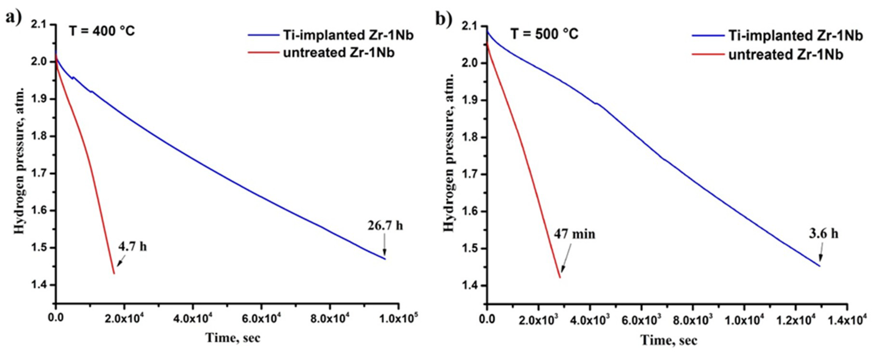
Rectangular samples with dimensions of 20 × 20 × 2 mm were cut from a cold-rolled Zr-1Nb sheet (composition: 0.9–1.1 Nb, 0.05 O, 0.015 Fe, 0.02 C, Zr balanced) and used as target material. The samples were ground and polished to eliminate surface defects and smooth the surface. Then the samples were ultrasonically cleaned in acetone for 20 min. According to the results of contact profilometry, the average surface roughness of the samples was Ra = 0.070 ± 0.005 μm. To relieve internal stresses, the samples were annealed in a vacuum at 580 °С for 3 h.
High-intensity low-energy ion implantation of titanium was carried out using experimental setup schematically illustrated in Reference [27]. For the generation of DC flow of metal plasma, a water-cooled vacuum arc evaporator was used, and the discharge current was equal to 130 A. The cathode of the evaporator was made of VT1-0 alloy (99.95% purity). A partially hemispherical grid electrode and a cylindrical drift section, made of stainless steel, were electrically attached and mounted on the axis of vacuum arc evaporator at the distance of 40 cm from the cathode working surface. The curvature radius of the grid electrode was 7.5 cm at the mesh size of 1.4 × 1.4 mm. The length of the cylindrical section was slightly longer than the focusing distance predefined by the grid curvature radius and equal to approx. 10 cm. For purification of vacuum arc plasma flow from the macroparticles, a metal disc mounted on the grid electrode preventing the straight flight of macroparticles to the irradiated area of the sample was used [32]. The residual gas pressure in the working chamber was equal to 10−3 Pa and slightly improved during the processing due to gas absorption (gettering) by titanium coating deposited on the chamber walls [33].
The formation of the ion beams in the presented approach is provided by the application of negatively pulsed bias to the system immersed in the plasma. A high voltage generator provided the amplitude of bias voltage of 1.5 kV, a pulse duration of 5 μs and pulse repetition rate of 105 pulses per second (p.p.s) was used. After the system biasing, a space charge separation layer usually referenced as sheath formed in front of the grid electrode and the process of ion extraction and acceleration occurred [34]. High ion current densities of vacuum arc plasma (equal to 5 mA/cm2 at the reference distance) provided the total extracted ion current up to 0.5 A with this geometry and voltage amplitude. After passing through the grid, ions entered the initially equipotential drift space, however, without the conditions of their space charge neutralization, they induced a significant potential drop due to their high perveance and, therefore, cannot propagate. Space charge neutralization in this system was realized due to the pulsed nature of the biasing voltage. During the off-pulse cycle vacuum, arc plasma, which has very high direction velocity of 2 × 10⁴ m/s streams into drift space and, in its turn, a very high degree of beam space charge neutralization, was achieved [35]. The beam focusing is almost defined by the ballistic trajectory to a very high current density of 100 mA/cm2. The ion current measurements were performed with Rogowski coil. More data concerning the processes of beam formation and its dynamics can be found in the Reference [36].
The implantation time was 60 min with the additional preheating for 15 min. The temperature of the irradiated target was measured by an isolated thermocouple mounted on backside of the sample and reached 700 °С. The dose of ion irradiation was estimated according to the formula [37]:
D = 6.25 × 10 18 × j × t × f × τ / Z
where j —ion current density, t —treatment time; f —pulse repetition rate; τ —pulse duration; Z —mean charge state of titanium ions. The calculated dose was D = 4.5 × 10²⁰ ion/cm2.

2.2. Hydrogenation

Hydrogenation was carried out using the automated complex Gas Reaction Controller LPB (Advanced Materials Corporation, Pittsburgh, PA, USA). Hydrogen was produced by pyrolysis method on hydrogen generator HyGen 200 (Wallingford, CT, USA). The purity of the generated hydrogen was 99.9995%. The hydrogenation was carried out at temperatures of 400 °C and 500 °C. The heating rate was 6 °C/min. After hydrogenation, the samples were cooled in a vacuum. The cooling rate was ~1.5–2 °C/min. The values of pressure and temperature in the reaction chamber were recorded every three seconds. Absolute hydrogen concentrations in the samples were measured by the hot extraction method using hydrogen analyzer RHEN602 (LECO, Saint Joseph, MO, USA) [38].

2.3. Characterization

Surface morphology and elemental composition were investigated by scanning electron microscopy (SEM) using TESCAN Mira II (Brno, Czech Republic) equipped with energy-dispersive X-ray (EDX) spectroscopy attachment (Oxford Analysis, Wiesbaden, Germany). For cross-section SEM analysis after hydrogenation, the polished samples were chemically etched with a solution of HNO3, HF, and H2O (45.5 and 50 vol.%, respectively). Depth distribution of elements was analyzed by glow-discharge optical emission spectroscopy (GDOES) using GD Profiler 2 (Horiba, Japan).
Crystalline structure and phase composition were analyzed by X-ray diffraction (Cu Kα radiation) using XRD 7000S diffractometer (Shimadzu, Japan) equipped with high-speed wide-range 1280 channels detector OneSight (Shimadzu, Japan). The diffraction data were analyzed using Sleve+ program. As a reference for the patterns of α-Zr, Zr0.7Ti0.3, Zr0.5Ti0.5, γ-ZrH and δ-ZrH the ICDD PDF-4+ database: #04-004-8479, #01-072-3354, #04-003-5040, #03-0656223 and #04-002-2839 was used, respectively.
Thermal desorption analysis (TDS) was carried out using Stanford Research Systems’ quadrupole mass spectrometer RGA100, which is a part of Gas Reaction Controller complex. The samples were heated up to 960 °C with the linear heating rate of 3 °C/min.

3. Results and Discussion

3.1. Structure and Composition of Ti-Implanted Zr-1Nb Alloy

Figure 1a shows the cross-section SEM image of the Zr-1Nb alloy after high-intensity ion implantation demonstrating the microstructure of the Ti-implanted layer. The thickness of this layer was 9.1 ± 1.4 μm. The implanted layer has a lamellar microstructure with disoriented coarse lamellar plates of the α′ martensitic phase and α(ZrTi) phase intertwined with each other (Figure 1a inset). The distribution of elements along the implanted layer was analyzed by EDX (Figure 1b). Titanium has gradient distribution through the implanted layer up to ~10 µm in depth. The highest concentration of titanium in the surface layer was 55 at.%.
Figure 2 shows X-ray diffraction analysis of Ti-implanted and as-received Zr-1Nb alloy. It can be observed that the as-received alloy is characterized by hexagonal close-packed (hcp) crystal structure with the lattice parameters a = 3.2364 Å and c = 5.1451 Å. The crystal structure of the surface layer significantly changed after high-intensity Ti ion implantation. In addition to the α phase of zirconium, intermetallic phases based on Zr-Ti compounds were formed. The Zr-Ti phases also had hcp α(α′) structure of different compositions: Zr0.5Ti0.5 (54 vol.%) and Zr0.7Ti0.3 (43 vol.%). The calculated values of lattice parameters of the phases and microstrains are presented in Table 1. It can be observed that the fraction of the residual α phase in the investigated volume is 4% after Ti ion implantation. A decrease in the lattice parameter a and an increase in the parameter c of α phase are observed. Therefore, the lattice distortion (increase in the c/a ratio) of the α zirconium phase occurs, which is most likely related to the formation of crystal lattice defects caused by incorporation of Ti atoms into Zr lattice. Higher microstrains after implantation also indicate the crystal lattice deformation.
The formation of Zr-Ti phases after ion implantation is attributed to a substitutional solid solution of Ti into Zr lattice [39]. The results are similar to the research of Zhou et al. [40] who showed that the binary Zr-Ti cast alloys with Ti concentration of 10 to 90 at.% are composed of α phase. However, the present study shows the formation of martensitic α′ phase in the surface modified layer confirmed by electron microscopy analysis. Such martensitic α′ phase is typical for the quenched Ti50Zr50 alloy as by Li et al. demonstrated [30]. Therefore, the presence of a martensitic phase indicates thermal induced phase transformations during ion implantation occurred. It has been reported that the transus temperature of β phase (Tβ) in Ti-Zr system with a high content of Zr is significantly lower than that in pure Ti or Zr [41]. The Tβ value for Ti0.5Zr0.5 is 600–620 °C according to References [30,41]. Considering that the implantation temperature was ~700 °C it is supposed that the formation of TiZr layer during implantation takes place in the β phase. Therefore, this layer undergoes β → α phase transformation during cooling after ion implantation. Cooling of the sample in a vacuum chamber occurred mainly due to radiative transfer; therefore, the cooling rate is proportional to σT4 in accordance with Boltzmann law, which favors the processes of martensitic transformations similar to quenching. The martensitic phases in Ti alloys are greatly dependent on the value of e/a in accordance with the valence electron theory. Lin et al. showed that the martensitic phase in Ti alloys with the value e/a below 4.07 should be α′ phase [42]. The e/a value for Ti-Zr system is four. Thus, the formation of α′ martensitic phase in the implanted layer is in agreement with this theory and other reported data on Ti-Zr systems.

3.2. Hydrogen Sorption Behavior

Hydrogenation was carried out at a constant temperature of 400 and 500 °C. Figure 3 shows the hydrogen sorption curves by the as-received and Ti-implanted alloy samples for comparison. The slope of the curves characterizes the intensity of hydrogen absorption by the samples. It can be observed that the formation of Ti-implanted layer significantly reduces hydrogenation of Zr-1Nb alloy. At the temperature of 400 °C, the as-received sample was hydrogenated to 530 ppm for 4.7 h, while the Ti-implanted sample for 26.7 h (CH = 400 ppm). The hydrogenation increased with temperature both for the as-received alloy and the alloy after ion implantation. The Ti-implanted samples were hydrogenated to 500 ppm for 3.6 h at 500 °С, while the as-received alloy for 47 min (CH = 650 ppm).
For quantitative analysis of hydrogenation, the hydrogen absorption rate was calculated using the following equation [24]:
Q = V t × S P 0 P P
where V —volume of the chamber (cm3), t —hydrogenation time, S —effective surface area of the samples (cm2), P 0 and P —starting and final pressure in the chamber (atm.), respectively.
The calculated values of the hydrogen absorption rate are presented in Table 2. The rate of hydrogen absorption by Zr-1Nb alloy was decreased by 6.3 times at 400 °C and 4.7 times at 500 °C due to the formation of Ti modified surface layer. It indicates the protective barrier properties of Ti-implanted layer against hydrogen permeation in the indicated temperature range.

3.3. Structure and Elemental Distribution in Hydrogenated Samples

The depth distribution of elements in a hydrogenated Ti-implanted sample is shown in Figure 4. The distribution of Ti and Zr elements through the depth is similar to those measured by EDX. Hydrogen in the modified layer has non-uniform distribution: The H concentration is the highest in the surface layer up to 1.5 µm in depth and then decreases with increasing analyzing depth. The Ti-contained layer could be divided into three sections. Due to a high concentration of hydrogen in the surface layer (I section), it would be expected that this layer consists of titanium-zirconium hydrides. The next section demonstrates the mixed Zr-Ti layer composed of two α′ + α(TiZr) phase with dissolved hydrogen. The third section is attributed to the intermediate layer mainly consisting of α zirconium phase distorted by titanium and hydrogen incorporation.
The crystalline structure of the hydrogenated samples is shown in Figure 5. The calculated phase content and lattice parameters are presented in Table 3. Zirconium hydrides with the cubic crystal structure (δ-ZrH1.66) and tetragonal γ-ZrH are detected in hydrogenated Zr-1Nb alloy. The content of δ hydrides in the analyzed depth is 53 vol.%. The α-Zr phase is also presented in the structure. However, the ratio of lattice parameters c/a of the α phase increased from 1.590 (as-received state) to 1.596 due to distortion of the crystal lattice by hydrogen dissolution. Inverse relationship (decrease in c/a ratio) is observed in the Ti-implanted samples. The latter may indicate that the presence of Ti in Zr lattice affects the position of hydrogen in the α phase. At the same time, a decrease in the intensity of α′-Zr0.5Ti0.5 reflex at the position of 2θ = 38.2° and an increase of the reflex at 2θ = 33.5° are observed (Figure 5b). The calculated phase composition indicates a decrease in the content of martensitic α′-Zr0.5Ti0.5 phase relative to the α(α′)-Zr0.7Ti0.3 phase (Table 3).
Such changes could be associated with the formation of hydrides in the surface modified layer. However, there are no pronounced reflexes corresponding to any hydride’s phases in the hydrogenated Ti-implanted sample (Figure 5b). Therefore, grazing incidence X-ray diffraction (GIXRD) was used for detailed analysis of the phase composition by the depth of the hydrogenated sample.
Figure 6 shows the XRD patterns recorded at different X-ray incidence angles (θ). It can be observed that the surface layer is primarily composed of α′-Zr0.5Ti0.5 phase (Figure 6 at θ = 5–10 degrees). In accordance with the results of the depth distribution of hydrogen and measured H concentration in the sample, we assume that the reflection at the position of 36.25° (θ = 5°) is attributed to TiZrH hydrides with fcc lattice structure. The intensity of α′-Zr0.5Ti0.5 reflections decreases while the reflection of α(α′)-Zr0.7Ti0,3 increases with analyzed depth (θ from 5 to 20°). This result indicates that the content of α(α′)-Zr0.7Ti0.3 is higher in the depth of Ti-implanted layer.
Microstructural analysis was performed on chemically etched samples before and after hydrogenation. The Ti-implanted layer, as mentioned above, consists of a lamellar microstructure with two pronounced layers: the upper layer with typical martensitic microstructure and the lower layer with elongated plates of α (TiZr) phase (Figure 7a). The latter seems to grow inside the primary β (TiZr) grains during cooling. Hydrogenation of the Ti-implanted layer has resulted in refinement of the lamellar plates and formation of a more homogeneous microstructure (Figure 7b). The upper layer with the thickness of about 1–2 µm has finer non-lamellar structure, which is probably attributed to the fragmentation of lamellar martensitic plates by TiZr hydrides precipitation.

3.4. Thermal Desorption Analysis

The characteristic of hydrogen desorption from hydrogenated Ti-implanted alloy was evaluated using thermal desorption spectroscopy. Figure 8 shows the TDS spectra of the Ti-implanted Zr-1Nb alloy at the heating rate of 3 °C/min. It can be observed that hydrogen release starts at approx. 250 °C. Deconvolution of the TDS spectra reveals one low-temperature peak (Peak I) and two high-temperature peaks (Peak II and III). The first peak corresponds to hydrogen desorption from the δ(Ti,Zr) hydrides followed by δ → β + δ → β(Ti,Zr) transformation in the implanted layer occurring at the valley between Peak I and Peak II. There are no published results related to decomposition of TiZrH hydrides, but the similar low-temperature desorption peak at 350–450 °C has been observed by many authors who studied the desorption of hydrogen from TiH hydrides [43,44]. In addition, in situ X-ray diffraction studies also indicate hydrides decomposition at these temperatures [45,46]. It is believed that the decomposition temperature of TiZrH hydrides is lower than that of δ-TiH or ZrH hydrides due to a reduced β transus temperature of TiZr compounds and β stabilizing effect of hydrogen. The next hydrogen desorption peak is related to equilibrium hydrogen pressure in the β(Ti, Zr) phase of the implanted layer and decomposition of δ zirconium hydrides in the alloy matrix followed by δ → β + δ → β(Zr) phase transformations [47]. According to Zr-H phase diagram, Peak III is attributed to the equilibrium hydrogen pressure of β(Zr) phase, therefore, corresponding to desorption of hydrogen from bcc β(Zr) phase of the zirconium alloy.
Thus, after analyzing the data on the hydrogen release, it could be concluded that the formation of TiZr implanted layer provides a lower temperature for hydrogen release and reduces the probability of hydrides formation in the surface layer of the alloy at temperatures of 350 °C and higher. At the same time, due to the low temperature of α → β(Ti, Zr) transformation, the TiZr layer can effectively trap the diffused hydrogen and is less susceptible to hydrogen embrittlement.

4. Conclusions

High-intensity low energy Ti ion implantation was used for surface modification of Zr-1Nb alloy. The microstructure and phase formation in TiZr surface modified layer, as well as its hydrogen interaction, were studied. Titanium has gradient distribution through the implanted TiZr layer up to 10 μm in depth. The modified TiZr layer was represented by α′ + α(TiZr) lamellar microstructure. The formation of martensite α′ plates after ion implantation was observed first and was probably related to fast cooling from the β(Ti,Zr) phase after the implantation process. Gas-phase hydrogenation was performed to evaluate the protective properties of the modified layer against hydrogen permeation into Zr-1Nb alloy. It was shown that the formation of TiZr layer provides a significant reduction of hydrogen uptake by zirconium alloy at 400 and 500 °C. Hydrogenation of the modified layer leads to refinement of lamellar plates and formation of a more homogenous microstructure. Thermal desorption spectroscopy revealed lower temperature for hydrogen desorption from TiZr layer. Due to lowering the temperature of α → β phase transformation by Ti addition, the Ti-modified layer can effectively trap the diffused hydrogen and is less susceptible to hydrogen embrittlement. The obtained results on high-intensity ion implantation and hydrogen interaction with TiZr can be used both to develop functional and protective deep layers on the surface of zirconium alloys, as well as to control the microstructure of the surface modified layer for various applications in industry or medicine

Author Contributions

Conceptualization and methodology, E.B.K. and A.I.R.; Validation, investigation and data curation, A.V.K., M.S.S., A.E.S., A.O. and S.W.; Writing-original draft preparation, E.B.K. and A.I.R.; Supervision, E.B.K.; Project administration and funding acquisition, E.B.K. and M.S.S.

Funding

The reported research was funded by the Russian Foundation for Basic Research and the government of the Tomsk region of the Russian Federation, grant No. 18-48-703034. The TDS analysis was funded by the Governmental program “Science”, research project No. 11.3683.2017/4.6.

Acknowledgments

The research was carried out within the framework of Tomsk Polytechnic University Competitiveness Enhancement Program.

Conflicts of Interest

The authors declare no conflict of interest.

References

  1. Sarkar, A.; Chandanshive, S.A.; Thota, M.K.; Kapoor, R. High temperature deformation behavior of Zr-1Nb alloy. J. Alloys Compd. 2017, 703, 56–66. [Google Scholar] [CrossRef]
  2. Lee, C.M.; Mok, Y.-K.; Sohn, D.-S. High-temperature steam oxidation and oxide crack effects of Zr-1Nb-1Sn-0.1Fe fuel cladding. J. Nucl. Mater. 2017, 496, 343–352. [Google Scholar] [CrossRef]
  3. Ensor, B.; Lucente, A.M.; Frederick, M.J.; Sutliff, J.; Motta, A.T. The role of hydrogen in zirconium alloy corrosion. J. Nucl. Mater. 2017, 496, 301–312. [Google Scholar] [CrossRef]
  4. Kishore, R. Effect of hydrogen on the creep behavior of Zr-2.5%Nb alloy at 723 K. J. Nucl. Mater. 2009, 385, 591–594. [Google Scholar] [CrossRef]
  5. Wei, T.; Long, C.; Chen, H. Hydrogen uptake behaviors of Zr-1.0Cr-0.4Fe-(0.2Mo) and N18 alloys during corrosion in 500 °C steam. J. Alloys Compd. 2018, 731, 126–134. [Google Scholar] [CrossRef]
  6. Couet, A.; Motta, A.T.; Comstock, R.J. Hydrogen pickup measurements in zirconium alloys: Relation to oxidation kinetics. J. Nucl. Mater. 2014, 451, 1–13. [Google Scholar] [CrossRef]
  7. Tagtstrom, P.; Limback, M.; Dahlback, M.; Andersson, T.; Pettersson, H. Effects of Hydrogen Pickup and Second- Phase Particle Dissolution on the In-Reactor Corrosion Performance of BWR Claddings. In Zirconium in the Nuclear Industry: 13th International Symposium, ASTM STP 1423; ASTM International: West Conshohocken, PA, USA, 2002; pp. 96–118. [Google Scholar]
  8. Krishna, K.M.; Srivastava, D.; Dey, G.K.; Hiwarkar, V.; Samajdar, I.; Banerjee, S. Role of grain/phase boundary nature on the formation of hydrides in Zr–2.5% Nb alloy. J. Nucl. Mater. 2011, 414, 270–275. [Google Scholar] [CrossRef]
  9. Bair, J.; Asle Zaeem, M.; Tonks, M. A review on hydride precipitation in zirconium alloys. J. Nucl. Mater. 2015, 466, 12–20. [Google Scholar] [CrossRef]
  10. McRae, G.A.; Coleman, C.E.; Leitch, B.W. The first step for delayed hydride cracking in zirconium alloys. J. Nucl. Mater. 2010, 396, 130–143. [Google Scholar] [CrossRef]
  11. Große, M.; Lehmann, E.; Steinbrück, M.; Kühne, G.; Stuckert, J. Influence of oxide layer morphology on hydrogen concentration in tin and niobium containing zirconium alloys after high temperature steam oxidation. J. Nucl. Mater. 2009, 385, 339–345. [Google Scholar] [CrossRef]
  12. Terrani, K.A. Accident tolerant fuel cladding development: Promise, status, and challenges. J. Nucl. Mater. 2018, 501, 13–30. [Google Scholar] [CrossRef]
  13. Cox, B. Some thoughts on the mechanisms of in-reactor corrosion of zirconium alloys. J. Nucl. Mater. 2005, 336, 331–368. [Google Scholar] [CrossRef]
  14. Duan, Z.; Yang, H.; Satoh, Y.; Murakami, K.; Kano, S.; Zhao, Z.; Shen, J.; Abe, H. Current status of materials development of nuclear fuel cladding tubes for light water reactors. Nucl. Eng. Des. 2017, 316, 131–150. [Google Scholar] [CrossRef]
  15. Kuprin, A.S.; Belous, V.A.; Voyevodin, V.N.; Vasilenko, R.L.; Ovcharenko, V.D.; Tolstolutskaya, G.D.; Kopanets, I.E.; Kolodiy, I.V. Irradiation resistance of vacuum arc chromium coatings for zirconium alloy fuel claddings. J. Nucl. Mater. 2018, 510, 163–167. [Google Scholar] [CrossRef]
  16. Bischoff, J.; Delafoy, C.; Vauglin, C.; Barberis, P.; Roubeyrie, C.; Perche, D.; Duthoo, D.; Schuster, F.; Brachet, J.-C.; Schweitzer, E.W.; et al. AREVA NP’s enhanced accident-tolerant fuel developments: Focus on Cr-coated M5 cladding. Nucl. Eng. Technol. 2018, 50, 223–228. [Google Scholar] [CrossRef]
  17. Alat, E.; Motta, A.T.; Comstock, R.J.; Partezana, J.M.; Wolfe, D.E. Multilayer (TiN, TiAlN) ceramic coatings for nuclear fuel cladding. J. Nucl. Mater. 2016, 478, 236–244. [Google Scholar] [CrossRef] [Green Version]
  18. Kim, I.; Khatkhatay, F.; Jiao, L.; Swadener, G.; Cole, J.I.; Gan, J.; Wang, H. TiN-based coatings on fuel cladding tubes for advanced nuclear reactors. J. Nucl. Mater. 2012, 429, 143–148. [Google Scholar] [CrossRef]
  19. Khatkhatay, F.; Jiao, L.; Jian, J.; Zhang, W.; Jiao, Z.; Gan, J.; Zhang, H.; Zhang, X.; Wang, H. Superior corrosion resistance properties of TiN-based coatings on Zircaloy tubes in supercritical water. J. Nucl. Mater. 2014, 451, 346–351. [Google Scholar] [CrossRef]
  20. Zou, Z.; Xue, W.; Jia, X.; Du, J.; Wang, R.; Weng, L. Effect of voltage on properties of microarc oxidation films prepared in phosphate electrolyte on Zr-1Nb alloy. Surf. Coat. Technol. 2013, 222, 62–67. [Google Scholar] [CrossRef]
  21. Van Nieuwenhove, R.; Andersson, V.; Balak, J.; Oberländer, B. In-Pile Testing of CrN, TiAlN, and AlCrN Coatings on Zircaloy Cladding in the Halden Reactor. In Zirconium in the Nuclear Industry: 18th International Symposium; ASTM International: West Conshohocken, PA, USA, 2018; pp. 965–982. [Google Scholar]
  22. Pushilina, N.S.; Kudiiarov, V.N.; Lider, A.M.; Teresov, A.D. Influence of surface structure on hydrogen interaction with Zr–1Nb alloy. J. Alloys Compd. 2015, 645, S476–S479. [Google Scholar] [CrossRef] [Green Version]
  23. Kashkarov, E.; Nikitenkov, N.; Sutygina, A.; Laptev, R.; Bordulev, Y.; Obrosov, A.; Liedke, M.O.; Wagner, A.; Zak, A.; Weiβ, S. Microstructure, defect structure and hydrogen trapping in zirconium alloy Zr-1Nb treated by plasma immersion Ti ion implantation and deposition. J. Alloys Compd. 2018, 732, 80–87. [Google Scholar] [CrossRef]
  24. Kashkarov, E.B.; Nikitenkov, N.N.; Sutygina, A.N.; Obrosov, A.; Manakhov, A.; Polčák, J.; Weiß, S. Hydrogen absorption by Ti-implanted Zr-1Nb alloy. Int. J. Hydrog. Energy 2018, 43, 2484–2491. [Google Scholar] [CrossRef]
  25. Peng, D.Q.; Bai, X.D.; Pan, F.; Sun, H.; Chen, B.S. Influence of titanium ions implantation on corrosion behavior of zirconium in 1 M H2SO4. Appl. Surf. Sci. 2006, 252, 2196–2203. [Google Scholar] [CrossRef]
  26. Obrosov, A.; Sutygina, A.; Manakhov, A.; Bolz, S.; Weiß, S.; Kashkarov, E. Oxidation Behavior of Zr–1Nb Corroded in Air at 400 °C after Plasma Immersion Titanium Implantation. Metals 2018, 8, 27. [Google Scholar] [CrossRef]
  27. Ryabchikov, A.I.; Kashkarov, E.B.; Pushilina, N.S.; Syrtanov, M.S.; Shevelev, A.E.; Korneva, O.S.; Sutygina, A.N.; Lider, A.M. High-intensity low energy titanium ion implantation into zirconium alloy. Appl. Surf. Sci. 2018, 439, 106–112. [Google Scholar] [CrossRef]
  28. Al-Nawas, B.; Brägger, U.; Meijer, H.J.A.; Naert, I.; Persson, R.; Perucchi, A.; Quirynen, M.; Raghoebar, G.M.; Reichert, T.E.; Romeo, E.; et al. A Double-Blind Randomized Controlled Trial (RCT) of Titanium-13Zirconium versus Titanium Grade IV Small-Diameter Bone Level Implants in Edentulous Mandibles—Results from a 1-Year Observation Period. Clin. Implant Dent. Relat. Res. 2012, 14, 896–904. [Google Scholar] [CrossRef] [PubMed]
  29. Ferreira, E.A.; Rocha-Filho, R.C.; Biaggio, S.R.; Bocchi, N. Corrosion resistance of the Ti–50Zr at.% alloy after anodization in different acidic electrolytes. Corros. Sci. 2010, 52, 4058–4063. [Google Scholar] [CrossRef]
  30. Li, Y.; Cui, Y.; Zhang, F.; Xu, H. Shape memory behavior in Ti-Zr alloys. Scr. Mater. 2011, 64, 584–587. [Google Scholar] [CrossRef]
  31. Frank, M.J.; Walter, M.S.; Lyngstadaas, S.P.; Wintermantel, E.; Haugen, H.J. Hydrogen content in titanium and a titanium–zirconium alloy after acid etching. Mater. Sci. Eng. C 2013, 33, 1282–1288. [Google Scholar] [CrossRef]
  32. Ryabchikov, A.I.; Ananin, P.S.; Dektyarev, S.V.; Sivin, D.O.; Shevelev, A.E. High intensity metal ion beam generation. Vacuum 2017, 143, 447–453. [Google Scholar] [CrossRef]
  33. Stout, V.L.; Gibbons, M.D. Gettering of gas by titanium. J. Appl. Phys. 1955, 26, 1488–1492. [Google Scholar] [CrossRef]
  34. Anders, A. (Ed.) Handbook of Plasma Immersion Ion Implantation and Deposition; Wiley: New York, NY, USA, 2000; Volume 17, p. 46. [Google Scholar]
  35. Yushkov, G.Y.; Anders, A.; Oks, E.M.; Brown, I.G. Ion velocities in vacuum arc plasmas. J. Appl. Phys. 2000, 88, 5618–5622. [Google Scholar] [CrossRef]
  36. Ryabchikov, A.I.; Sivin, D.O.; Korneva, O.S.; Lopatin, I.V.; Ananin, P.S.; Prokopenko, N.A.; Akhmadeev, Y.K. High-current-density gas ion ribbon beam formation. Nucl. Instrum. Methods Phys. Res. Sect. A Accel. Spectrom. Detect. Assoc. Equip. 2018, 906, 56–60. [Google Scholar] [CrossRef]
  37. Richmond, C.J. Ion Implantation; Ryssel, H., Ruge, I., Eds.; Wiley: Chichester, UK, 1986; 478p. [Google Scholar]
  38. Babikhina, M.N.; Kudiiarov, V.N.; Mostovshchikov, A.V.; Lider, A.M. Quantitative and Qualitative Analysis of Hydrogen Accumulation in Hydrogen-Storage Materials Using Hydrogen Extraction in an Inert Atmosphere. Metals 2018, 8, 672. [Google Scholar] [CrossRef]
  39. Dobromyslov, A.V.; Taluts, N.I. Structure investigation of quenched and tempered alloys of the Zr–Ti system. Phys. Met. Met. 1987, 63, 114–120. [Google Scholar]
  40. Zhou, Y.K.; Jing, R.; Ma, M.Z.; Liu, R.P. Tensile strength of Zr-Ti binary alloy. Chin. Phys. Lett. 2013, 30, 116201. [Google Scholar] [CrossRef]
  41. Liang, S.X.; Yin, L.X.; Zhou, Y.K.; Feng, X.J.; Ma, M.Z.; Liu, R.P.; Tan, C.L. Abnormal martensitic transformation of high Zr-containing Ti alloys. J. Alloys Compd. 2014, 615, 804–808. [Google Scholar] [CrossRef]
  42. Lin, C.; Yin, G.; Zhao, Y.; Ge, P.; Liu, Z. Analysis of the effect of alloy elements on martensitic transformation in titanium alloy with the use of valence electron structure parameters. Mater. Chem. Phys. 2011, 125, 411–417. [Google Scholar] [CrossRef]
  43. Ma, M.; Liang, L.; Wang, L.; Wang, Y.; Cheng, Y.; Tang, B.; Xiang, W.; Tan, X. Phase transformations of titanium hydride in thermal desorption process with different heating rates. Int. J. Hydrog. Energy 2015, 40, 8926–8934. [Google Scholar] [CrossRef]
  44. Suwarno, S.; Yartys, V.A. Kinetics of hydrogen absorption and desorption in titanium. Bull. Chem. React. Eng. Catal. 2017, 12, 312–317. [Google Scholar] [CrossRef]
  45. Laptev, R.S.; Syrtanov, M.S.; Kudiiarov, V.N.; Shmakov, A.N.; Vinokurov, Z.S.; Mikhaylov, A.A.; Zolotarev, K.V. In Situ Investigation of Thermo-stimulated Decay of Hydrides of Titanium and Zirconium by Means of X-ray Diffraction of Synchrotron Radiation. In Physics Procedia; Elsevier: Amsterdam, The Netherlands, 2016; Volume 84, pp. 337–341. [Google Scholar]
  46. Jiménez, C.; Garcia-Moreno, F.; Pfretzschner, B.; Klaus, M.; Wollgarten, M.; Zizak, I.; Schumacher, G.; Tovar, M.; Banhart, J. Decomposition of TiH2studied in situ by synchrotron X-ray and neutron diffraction. Acta Mater. 2011, 59, 6318–6330. [Google Scholar] [CrossRef]
  47. Ma, M.; Liang, L.; Tang, B.; Xiang, W.; Wang, Y.; Cheng, Y.; Tan, X. Decomposition kinetics study of zirconium hydride by interrupted thermal desorption spectroscopy. J. Alloys Compd. 2015, 645, S217–S220. [Google Scholar] [CrossRef]
Figure 1. Cross-section scanning electron microscopy (SEM) image of (a) Ti-implanted Zr-1Nb and (b) depth distribution of elements measured by EDX.
Metals 08 01081 g001
Figure 2. X-ray diffraction (XRD) patterns of (a) as-received and (b) Ti-implanted Zr-1Nb alloy.
Metals 08 01081 g002
Figure 3. Hydrogen pick-up curves at (a) 400 °С and (b) 500 °С.
Metals 08 01081 g003
Figure 4. Glow-discharge optical emission spectroscopy (GDOES) profiles of elements in Ti-implanted alloy hydrogenated at 500 °C.
Metals 08 01081 g004
Figure 5. XRD patterns of (a) hydrogenated Zr-1Nb and (b) Ti-implanted Zr-1Nb alloy.
Metals 08 01081 g005
Figure 6. Grazing incidence X-ray diffraction (GIXRD) patterns of the hydrogenated Ti-implanted alloy.
Metals 08 01081 g006
Figure 7. Cross-section SEM images of chemically etched Ti-implanted Zr-1Nb alloy (a) before and (b) after hydrogenation.
Metals 08 01081 g007
Figure 8. Thermal desorption analysis (TDS) spectra of the hydrogenated Ti-implanted Zr-1Nb alloy.
Metals 08 01081 g008
Table 1. The results of X-ray diffraction (XRD) analysis.
SamplePhasePhase Content, %Lattice Parameters, Åc/a Microstrain   Δ d / d ,   10 3
Zr-1Nbα-Zr (hcp)100a = 3.2364
c = 5.1451
1.5901.5
Ti-implanted Zr-1Nbα-Zr (hcp)4a = 3.2325
c = 5.1507
1.5942.2
Zr0.5Ti0.5(hcp)54a = 3.0886
c = 4.8438
1.5684.3
Zr0.7Ti0.3(hcp)43a = 3.1613
c = 5.0229
1.5894.8
Table 2. Hydrogen absorption rate.
Temperature, °CHydrogen Absorption Rate Q, ×10−6 cm3Н2/(s∙cm2)Reduction Ratio
Zr-1Nb AlloyTi-implanted Zr-1Nb
4004.40.76.3
50028.76.14.7
Table 3. Phase composition and lattice parameters of the phases in hydrogenated samples.
SamplePhaseContent, vol.%Lattice Parameter, Åc/a
Zr-1Nbα-Zr (hcp)42a = 3.2347;
c = 5.1624
1.596
δ-ZrH1.66 (fcc)53a = 4.7654-
γ-ZrH (fct)5a = 4.5811;
c = 4.9612
1.083
Ti-implanted Zr-1Nbα-Zr (hcp)4a = 3.2567;
c = 5.1508
1.582
Zr0.5Ti0.5 (hcp)50a = 3.0901;
c = 4.8931
1.583
Zr0.7Ti0.3 (hcp)46a = 3.1899;
c = 4.9612
1.555

