Influences of Pin Shape on a High Rotation Speed Friction Stir Welding Joint of a 6061-T6 Aluminum Alloy Sheet

1
School of Computer Science and Engineering, Jiangsu University of Science and Technology, Zhenjiang 212003, China
2
School of Material Science and Engineering, Jiangsu University of Science and Technology, Zhenjiang 212003, China
*
Author to whom correspondence should be addressed.
Metals 2018, 8(12), 987; https://doi.org/10.3390/met8120987
Submission received: 30 October 2018
/
Revised: 20 November 2018
/
Accepted: 21 November 2018
/
Published: 24 November 2018
(This article belongs to the Special Issue Friction Stir Welding and Processing in Alloy Manufacturing)
Abstract
:In order to explore the influences of different pins on the weld based on the specialty of the aluminium alloy sheet welding, three kinds of pins were chosen to perform high rotation speed friction stir welding on a 1 mm thick 6061-T6 aluminium alloy in this study. The microstructure and mechanical properties of the joints were analysed at the same time. When the rotation speed was 11,000 rpm and the welding speed was 300 mm/min, more sufficient stirring and a better joint (the tensile strength reaches 87.2% of the base metal) can be obtained with the pin design of a quadrangular frustum pyramid. The pattern of the weld cross section was a “flat T” and no obvious “S curve” was found in nugget zone (NZ). Heat affected zone (HAZ) and thermo-mechanically affected zone (TMAZ) were also narrow. The results demonstrate that the proportion of low angle boundaries in each area of the weld is lower than that of traditional Friction Stir Welding (FSW). The grain size of NZ is significantly refined and the proportion of low angle boundaries is only 20.1%, which have improved the welding quality.
1. Introduction
Due to its low density and high strength, the aluminum alloy has been widely used in aerospace, automobile, machinery manufacturing, shipping, and chemical industries [1]. Steel is replaced by a high-strength aluminum alloy sheet in order to conserve energy by reducing the vehicle weight, especially in the automobile manufacturing industry [2,3].
Nevertheless, defects and deformation appear during the aluminum alloy sheet welding process as results of non-uniform heating, inappropriate welding parameters, etc. Furthermore, certain defects in the fusion welding process, such as pores or cracks, are attributed to the limitation of the weld ability of the aluminum alloy [4]. However, Friction Stir Welding (FSW) can achieve solid-state welding without filler materials, which effectively avoids cracks and porosity defects [5,6,7,8,9,10]. Scialpi et al. successfully conducted ultra-micro-friction stir welding on 0.8 mm 2024-T3 and 6082-T6 sheets, and analyzed the mechanical properties [11]. Tong et al. tested traditional FSW on a 1 mm aluminum alloy sheet [12]. The range of welding parameters and relevant mechanical properties were studied in existing work, which mainly focused on traditional FSW with a rotation speed lower than 1000 rpm [13,14].
Recent research reported that the rotation speed can reach 10 times or more that of traditional FSW [15]. For the higher welding speed and the smaller welding deformation, high rotation FSW is more suitable for aluminum alloy sheet welding [16,17]. Additionally, the technique is expected to be used for robotic welding because of its lower axial pressure [18]. Given the value of application, it merits further study. However, there are scarce research studies examining the joints of high rotation speed friction stir welding (HSFSW).
It is well-known that the pin shape of the tool impacts the FSW process. Additionally, the geometric optimization of the pin shape influences the welding quality [19]. Elangovana et al. pointed out that the tool geometry is a predominant factor determining the weld forming, localized heating, and stirring action [20]. At the same time, the plastic metal flow behavior is mainly influenced by the pin profile, pin dimensions, and FSW process parameters [21]. Compared with the traditional FSW, the smaller size tool is needed and less material is involved in the plastic metal flow in the HSFSW welding process [22,23]. However, few research studies have studied the effects of the pin on the weld microstructure under the high rotation speed condition [24,25]. Therefore, it is necessary to examine the impacts of the pin shape on the welding quality and the microstructure of the joint.
It is important to design a reasonable pin so as to stir these few plastic metals effectively. In this study, three kinds of pin shape were chosen to perform HSFSW on a 1mm thick 6061-T6 aluminum alloy. The hardness and microstructure of the weld cross-section were analyzed. Furthermore, the Electron Backscattered Diffraction system (EBSD) samples were also prepared to reveal the microstructure and mechanical properties under the condition of high rotation speed.
2. Experiment Materials and Methods
The high rotation speed FSW machine used in this study is shown in Figure 1. The FSW tools are all made of hot-work abrasives steel. The diameter of the tool shoulder is 7 mm, but the shapes of the pins are different (Figure 2). FSW tools with different pins are denoted as S1, S2 and S3. As shown in Figure 2, S1, S2 and S3 are a quadrangular prism, quadrangular frustum pyramid, and frustum, respectively. The length of these pins is 0.9 mm.
The base metal selected is a 6061-T6 aluminum sheet (150 mm × 80 mm × 1 mm) with a tensile strength of 304 MPa, good ductility, corrosion resistance, and no stress corrosion cracking tendency during the welding process [26]. Its composition is shown in Table 1.
During the prewelding process, the workpieces should be rigidly fixed to the worktable. The butt weld configuration is used in the experiments. The rotation speed selected during the welding process is 11,000 rpm, and the welding speed varies from 200 mm/min to 500 mm/min. In addition, the position control is selected for each welding experiment, and the plunge depth of the shoulder is kept at 0.05 mm.
3. Experimental Results
3.1. The Visual Testing
The weld surface is shown in Table 2 and Figure 3. As we can see from Table 2, pin shape and travel speed (V) can affect weld surface quality, even though the rotation speed remains the same. When the travel speed is 200 mm/min, the weld surface is poor, regardless of pin shape. In the case of S1, a groove appears along the weld seam and seriously flashes on both sides of the weld. In the case of S2, the surface of the weld is rough. In the case of S3, a groove appears along the weld.
When the V is 300 mm/min, the soundable appearance of the weld is obtained by using the S1, S2, and S3 tools. But if the V reaches 400 mm/min, a smooth surface can only be obtained by using S2 and S3. When the travel speed is 500 mm/min, the surface of all welds has groove defects.
It can be noted that a too low or too high travel speed is not suitable for sheet welding. The lower travel speed leads to the accumulation of heat in the welding area, causing the over plasticization of metal in the welding area and inevitably flashes. The groove will thereupon appear in the case that the plasticized metal is extruding too much. As for the other extreme, the higher travel speed results in inadequate heat input, and then insufficient plasticization makes the metal filling cycle incomplete, leading to groove defects. For the 1 mm thick 6061-T6 aluminum alloy sheet, the welding process window of the S2 FSW tool is wider than that of S1 and S3.
3.2. Axial Force
Due to its lower axial pressure, HSFSW is expected to be used for robotic welding. In the previous experiments, the axial force with different rotation speeds was collected (Figure 4). When the diameter of tool shoulder is 7 mm, the axial force decreases as the rotation speed increases. The average axial force is 1.375 KN while the rotation speed is 11,000 rpm.
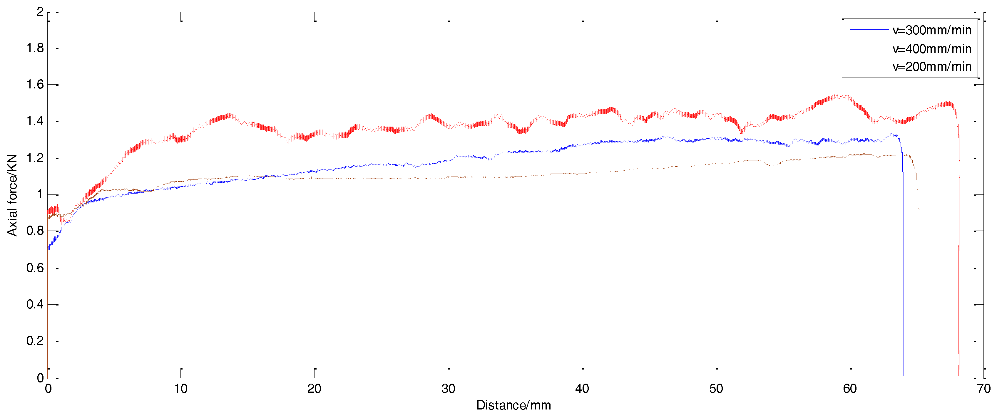
In the experiments for this paper, the axial force with different travel speeds during the whole process was collected (Figure 5). As the diameter of the tool shoulder and the rotation speed are fixed, the axial force during the whole process fluctuates a little, but the average axial force increases while the travel speed also increases.
3.3. Macro Morphology and Micro Hardness
Three tensile specimens (W1, W2, W3) corresponding to S1, S2, and S3 tools were prepared by wire-electrode cutting. As shown in Figure 6, the “flat T” pattern of the cross-sections of the joints W1, W2, and W3 can be observed by a metallographic microscope. Due to the differences between the shapes of the pins, the boundary lines of the joint W1 are approximately perpendicular to the weld surface, the joint W3 has a larger gradient of the boundary line, and the joint W2 has the largest degree of inclination. Obviously, there are hole defects at the bottom boundary of NZ and TMAZ on AS of both W1 and W3.
There are some similarities between the three joints, as shown in Figure 6. The nugget zone (NZ) is darker than other zones, which is because the grains in NZ are finer than those in other zones. A clear demarcation exists between the nugget zone (NZ) and thermo-mechanically affected zone (TMAZ). TMAZ is located between NZ and the heat affected zone (HAZ). Nevertheless, there is no clear dividing line between HAZ and the base-metal (BM). At the same time, no obvious “S curve” is found in all joints. An “S curve” is usually caused by the surface oxidation film, which is not completely broken by the stirring during the traditional FSW process [27]. Three regions in AS were chosen to be scanned to detect the presence of an oxide film (Figure 6b). Oxide is obviously present and gathers in a small scale. Therefore, the aggregations are scattered (Figure 7). It can be seen that the stirring effect can be greatly improved in high rotation speed conditions. The oxide film rubbed against the shoulder and the pin of the FSW tool is completely crushed and stirred into the weld metal and cannot form a continuous distribution.
The hardness curves of joints are shown in Figure 8. Three straight lines (L1, L2, L3) are selected. L2 is located in the weld center, the distance between the L1 and the upper surface is 0.2 mm, and the distance between the L3 and the bottom is 0.2 mm. The interval of two measurement points is 0.2 mm.
As displayed in Figure 8, the hardness curve of the weld cross-section is roughly “W”. The hardness value in BM-HAZ-TMAZ-NZ declines first, and then gradually increases. This is mainly because HAZ is only subjected to thermal cycling and then the grains grow slightly bigger than that of BM. NZ is mainly composed of small equiaxed grains, so its hardness is higher than that of HAZ and TMAZ.
Figure 8d compares the average hardness of different welds. The hardness of all weld zones corresponding to W1 and W3 is lower than that of W2. In terms of the hardness distribution, the pin design of the quadrangular frustum pyramid results in more fully stirring and better joints.
3.4. Tensile Properties of the Joint
Tensile tests on the welded joints fabricated by S1, S2 and S3 FSW tools were carried out. The specimens were tested on Electro-mechanical Universal Testing Machines (Shandong Liangong Testing Machines Co., Ltd, Jinan, China), and the specimen dimensions are shown in Figure 9. The length of the specimen is 160 mm, the width of the specimen is 12 mm, the head width is 24 mm, and the transition radius is 30 mm. The test results are shown in Figure 10 and Figure 11. The tensile strength of specimen W1, W2, and W3 is 160 MPa, 265 MPa, and 214 MPa, respectively, accounting for 52.6%, 87.2% and 70.4% of the base metal. Because the samples are not fully fixed to the testing machine, the stress stays nearly constant but the strain increases in Figure 10, which is inevitable.
As is shown in Figure 11, the fracture locations and forms of joints are different. The fracture location of the specimen W1 is located at the junction of HAZ and NZ on the AS and the tensile strength is poor, and it is near the hole defects on W1. The fracture location of the specimen W2 is at the junction of HAZ and BM on the RS. The fracture location of the specimen W3 is located at the boundary between HAZ and TMAZ of AS close to the hole defects, with the tensile strength and elongation between W1 and W2. Obviously, the defects lead to a fracture with the tensile strength.
4. Discussion
4.1. Microstructure of the Fracture
Because of the different shapes of the pins, the ability of the plastic metal to move along the vertical direction varies. The cross section of the weld W1, W2, and W3 is shown in Figure 12. The boundaries of the various zones of the AS are more obvious, but not in the RS.
For the specimen W1, there is an obvious hole defect at the bottom boundary of NZ and TMAZ, even if it has a smooth weld surface, as shown in Figure 12b. As the side of the prism is perpendicular to its bottom, the plastic metal is stirred only on the horizontal plane and fails to smoothly transition from NZ.
For a quadrangular frustum pyramid pin, the angle between its side and the bottom is an obtuse angle, the plastic metal flowing in the vertical and horizontal direction means that the plastic metal fully stirred, and the transition from TMAZ to NZ is smooth. As is shown in Figure 12c,d, the microstructures of TMAZ and NZ are compact, and almost no boundary line exists at the bottom of the weld.
As is shown in Figure 12f, hole defects are also generated in the specimen W3, even if the angle between the side of the pin and the bottom is also an obtuse angle. Due to the smooth outer surface, the conical pin is weaker on stirring in the horizontal direction in the welding process, and then it reduces the amount of plastic metals involved in the stirring. Naturally, an uneven transition between TMAZ and NZ occurs.
A closer analysis revealed that the advancing side easily develops defects, which is mainly caused by an insufficient flow of plastic metals. As discussed above, we can note that the pin with four prisms cannot provide the driving force in the vertical direction and the weld is apt to defects. The conical pin possesses the ability to drive plastic metal in a vertical direction, but it is weaker on stirring in the horizontal direction in the welding process because of the smooth shape, and inevitably, the weld shows tunnel defects. The defects of these two shapes are both located at the junction of HAZ and NZ on the advancing side of the weld. On the contrary, the shape of the frustum pin generates a good weld and the fracture appears in the junction of HAZ and BM on the RS of the weld.
4.2. Grain Characteristics of HSFSW
In order to further reveal the grain characteristics by using a frustum pin, the Electron Backscattered Diffraction system (EBSD), was used to analyze the various zones of the joint. The grain orientation distribution, the grain size, and the grain deformation degree were analyzed at the same time.
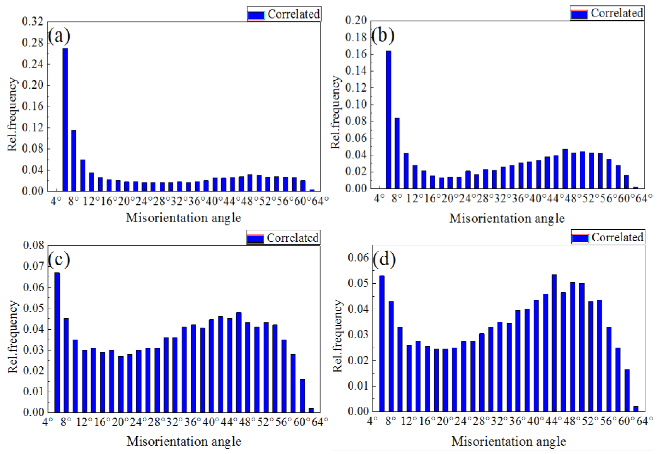
The characteristics of BM are shown in Figure 13a. The grains are lath-like and their average diameter is 16.3 μm. There are also a large number of low angle boundaries (2° < θ < 15°, θ is the grain boundary orientation angle), which is confirmed in Figure 14a. As shown in Figure 13b, HAZ is still dominated by small angle grain boundaries and the average grain diameter is 16.9 μm because of the heat cycle during the welding process.
The NZ is composed of equiaxed grains (the average grain diameter is 9.3 μm) with high angle boundaries (θ > 15°) in Figure 13d. The transformation from low angle grain boundaries continuously increases the number of high angle grain boundaries and finally the grains are significantly refined. The composition of the TMAZ is similar to that of the NZ, but there are more deformed grains in the TMAZ, and the grains are irregular (Figure 13c).
For the traditional FSW, the average grain size of HAZ is 18.2–18.9 μm, and the average grain size of NZ is 9.1–9.7 μm [28]. That is to say, the high speed does not produce too much heat and the grain size of the HSFSW joint is similar to that of traditional FSW.
4.3. Grain Orientation Distribution Map
The orientation difference between the adjacent grains of the deformed structure also affects the deformation and fracture behavior of the weld seam. Owing to a large number of deformed structures inside the aluminum alloy sheet before welding (Figure 14a), the distortion energy is very low, and dynamic recrystallization does not occur here. The grain orientation distribution of HAZ is shown in Figure 14b. Similar to that of BM (57.5%), a large number of low angle boundaries still exist, but the proportion slightly decreases to 50%. This is because HAZ is mainly affected by thermal cycling. The grain structure only slightly grows along the deformation direction and the orientation difference almost does not change.
Figure 14c shows the grain orientation distribution of TMAZ. The proportion of low angle boundaries is 23.3%, which shows that the proportion of high angle boundaries increases and the grain structure has undergone significant changes. Large plastic deformation exits near the nugget zone, subjected to both thermal cycling and shearing stress, so the internal energy and atomic activity increase. With the slip and accumulation of dislocations, subgrain boundaries with extremely low misorientation were finally produced. Subgrain boundaries firstly changed into low angle boundaries, and then gradually transformed into high angle boundaries owing to continuous dynamic recovery and recrystallization. Therefore, the equiaxed grains surrounded by high angle boundaries have no sub-structure. However, the grains away from NZ are mainly affected by the thermal cycle and still have low angle boundaries.
Compared with BM, the proportion of low angle boundaries in NZ is significantly reduced to 20.1% (Figure 14d). According to the existing research on the traditional FSW joints of the 1 mm 6061-T6 aluminum alloy, the proportion of low angle boundaries in HAZ accounted for 70.5%, in TMAZ accounted for 60.3%, and in NZ accounted for 55.46% [29,12]. Obviously, the proportion of low angle boundaries in all zones in our research is lower than that of the traditional FSW, which indicates that the number of high angle boundaries can effectively hinder the crack expansion and greatly improve the connection strength of the weld. By high rotation speed, the grains in the NZ are simultaneously subjected to the squeezing and stronger shearing force of the tool, the dislocation density increases continuously, and the orientation deviation of low angle boundaries increases. Once recrystallization occurs, new equiaxed grains emerge and the low angle boundaries are soon changed into high angle boundaries. However, the crystal nucleus in NZ was mechanically broken without an increase, and was then transformed into small equiaxed grains, which have much a smaller diameter than that of BM.
5. Conclusion
Three kinds of pins are selected to perform high rotation speed FSW on a 1 mm 6061-T6 aluminum alloy sheet. When the shape of the pin is a quadrangular frustum pyramid, the rotation speed is 11,000 rpm and the travel speed is 300 mm/min, and soundable joints are obtained. Due to the stirring effect of high rotation speed, the proportion of low angle boundaries in all zones is lower than that of the traditional FSW, while the average grain size is similar to traditional FSW. The proportion of low angle boundaries in HAZ, TMAZ, and NZ is 50%, 23.3%, and 20.1%, respectively. The tensile strength of specimen W2 is 265 MPa, which accounts for 87.2% of the base metal. The pattern of the weld cross section is “flat T”. HAZ and TMAZ are narrow and no obvious “S curve” is found in the weld, which is different from the traditional FSW.
Author Contributions
Data curation formal analysis, writing-original draft, and Writing—review & editing, Y.Z.; methodology and conceptualization, J.W.; funding acquisition, S.C.; project administration, P.W.; resources and investigation, J.X.
Funding
This research was funded by the Qing Lan Project, National Post Doctoral Fund and the National Natural Science Foundation of China (51675248) and the Natural Science Fund of the Jiangsu Higher Education Institutions of China (17KJA460006).
Acknowledgments
The authors would like to thank the support of the laboratories and the help of Wu Yunkai for writing the draft.
Conflicts of Interest
The authors declare no conflict of interest.
References
- Palanivel, R.; Mathews, P.K.; Murugan, N.; Dinaharan, I. Effect of tool rotational speed and pin profile on microstructure and tensile strength of dissimilar friction stir welded AA5083-H111 and AA6351-T6 aluminum alloys. Mater. Des. 2012, 40, 7–16. [Google Scholar] [CrossRef]
- Sasabe, S.; Eguchi, N.; Ema, M.; Matsumoto, T. Laser welding characteristics of aluminium alloys for automotive applications. Weld. Int. 2003, 17, 870–878. [Google Scholar] [CrossRef]
- Haraga, K.; Kanesaka, T.; Mabuchi, A. Strength properties of aluminum/aluminum and aluminum/steel joints for light weighting of automotive body. Weld. World 2000, 44, 23–27. [Google Scholar]
- Liang, H.M.; Yan, K.; Wang, Q.Z.; Zhao, Y.; Liu, C.; Zhang, H. Improvement in joint strength of spray-deposited Al-Zn-Mg-Cu alloy in underwater friction stir welding by altered temperature of cooling water. J. Mater. Eng. Perform. 2016, 25, 1–8. [Google Scholar] [CrossRef]
- Çam, G.; Mistikoglu, S. Recent developments in friction stir welding of Al-alloys. J. Mater. Eng. Perform. 2014, 23, 1936–1953. [Google Scholar] [CrossRef]
- Song, K.H.; Tsumura, T.; Nakata, K. Development of microstructure and mechanical properties in Laser-FSW hybrid welded Inconel 600. Mater. Trans. 2009, 50, 1832–1837. [Google Scholar] [CrossRef]
- Song, S.W.; Kim, B.C.; Yoon, T.J.; Kim, N.K.; Kim, I.B.; Kang, C.Y. Effect of welding parameters on weld formation and mechanical properties in dissimilar Al alloy joints by FSW. Mater. Trans. 2010, 51, 1319–1325. [Google Scholar] [CrossRef]
- Rhodes, C.G.; Mahoney, M.W.; Bingel, W.H.; Spurling, R.A.; Bampton, C.C. Effects of friction stir welding on microstructure of 7075 aluminum. Scr. Mater. 1997, 36, 69–75. [Google Scholar] [CrossRef]
- Sutton, M.A.; Yang, B.; Reynolds, A.P.; Taylor, R. Microstructural studies of friction stir welds in 2024-T3 aluminum. Mater. Sci. Eng. A 2002, 323, 160–166. [Google Scholar] [CrossRef]
- Lu, S.; Jia, X.D.; Zhang, C.Y.; Fu, L.; Dong, X.Y. Temperature field and microstructure of magnesium alloy fabricated by FSW. J. Mater. Eng. Perform. 2009, 1, 9–13. [Google Scholar]
- Scialpi, A.; Giorgi, M.D.; Filippis, L.A.C.D.; Nobile, R.; Panella, F.W. Mechanical analysis of ultra-thin friction stir welding joined sheets with dissimilar and similar materials. Mater. Des. 2008, 29, 928–936. [Google Scholar] [CrossRef]
- Tong, J.H.; Li, L.; Deng, D.; Wan, F.R. Friction stir welding of 6061-T6 aluminum alloy thin sheets. J. Univ. Sci. Technol. Beijing 2008, 30, 1011–1017. [Google Scholar]
- Serio, L.M.; Palumbo, D.; De Filippis, L.A.C.; Galietti, U.; Ludovico, A.D. Effect of Friction Stir Process Parameters on the Mechanical and Thermal Behavior of 5754-H111 Aluminum Plates. Materials 2016, 9, 122. [Google Scholar] [CrossRef] [PubMed]
- De Filippis, L.A.C.; Serio, L.M.; Palumbo, D.; De Finis, R.; Galietti, U. Optimization and characterization of the Friction Stir Welded Sheets of AA 5754-H111: Monitoring of the quality of joints with thermographic techniques. Materials 2017, 10, 1165. [Google Scholar] [CrossRef] [PubMed]
- Zhao, H.H.; Feng, X.S.; Xiong, Y.Y.; Li, H.J.; Dong, F.B.; Hu, L.; Guo, L.J. Study on the temperature distribution of 6061 aluminium alloy micro friction stir welding featured high speed without inclination. Electr. Weld. Mach. 2014, 44, 71–77. [Google Scholar]
- Qin, G.L.; Zhang, K.; Zhang, W.B.; Wu, C.S. Effect of friction stir welding heat input on weld appearance and mechanical properties of 6013-T4 Al alloy joint. Trans. China Weld. Inst. 2010, 31, 5–8. [Google Scholar]
- Tian, Z.J.; Su, Z.Q.; Gao, Y.J.; Xu, S.J.; S, S.X. Research on FSW and VPPA intercross welding of 2219 aluminum alloy. Weld. Technol. 2013, 42, 24–26. [Google Scholar]
- Chen, S.J.; Zhou, Y.; Xue, J.R.; Ni, R.Y.; Guo, Y.; Dong, J.H. High rotation speed friction stir welding for 2014 aluminum alloy thin sheets. J. Mater. Eng. Perform. 2017, 26, 1–9. [Google Scholar] [CrossRef]
- Chen, Y.C.; Liu, H.J.; Feng, J.C. Friction stir welding characteristics of different heat-treated-state 2219 aluminum alloy plates. Mater. Sci. Eng. A 2006, 420, 21–25. [Google Scholar] [CrossRef]
- Elangovan, K.; Balasubramanian, V. Influences of pin profile and rotational speed of the tool on the formation of friction stir processing zone in AA2219 aluminiumalloy. Mater. Sci. Eng. A 2007, 459, 7–18. [Google Scholar] [CrossRef]
- Liu, H.J.; Chen, Y.C.; Feng, J.C. Effect of zigzag line on the mechanical properties of friction stir welded joints of an Al–Cu alloy. Scr. Mater. 2006, 55, 231–234. [Google Scholar] [CrossRef]
- Zhang, Z.; Liu, H.J. Effect of pin shapes on material deformation and temperature field in friction stir welding. Trans. China Weld. Inst. 2011, 32, 5–8. [Google Scholar]
- Galvão, I.; Leal, R.M.; Rodrigues, D.M.; Loureiro, A. Influence of tool shoulder geometry on properties of friction stir welds in thin copper sheets. J. Mater. Process. Technol. 2013, 213, 129–135. [Google Scholar] [CrossRef] [Green Version]
- Faraji, G.; Asadi, P. Characterization of AZ91/alumina nanocomposite produced by FSP. Mater. Sci. Eng. A 2011, 528, 2431–2440. [Google Scholar] [CrossRef]
- Azizieh, M.; Kokabi, A.H.; Abachi, P. Effect of rotational speed and probe profile on microstructure and hardness of AZ31/Al2O3, nanocomposites fabricated by friction stir processing. Mater. Des. 2011, 32, 2034–2041. [Google Scholar] [CrossRef]
- Chen, Z.; Zhou, Y.L.; Tian, B.; Zhang, T.; Liu, Y.J. Research on FSW of 6061 aluminum alloy. Electr. Weld. Mach. 2011, 41, 95–98. [Google Scholar]
- Xie, T.F.; Xing, L.; Ke, L.M.; Luan, G.H.; Dong, C.L. Influence of Pin geometry on formation of lazy S in Friction Stir Welding. Hot Work. Technol. 2008, 37, 64–66. [Google Scholar]
- Jia, Y.; Wang, K.H.; Yang, L.; Wang, X.J. Analysis on Microstructure of 6061 Al Alloy with Friction Stir Welding. Hot Work. Technol. 2015, 44, 180–182. [Google Scholar]
- Wang, B.; Lei, B.B.; Zhu, J.X.; Feng, Q.; Wang, L.; Wu, D. EBSD study on microstructure and texture of friction stir welded AA5052-O and AA6061-T6 dissimilar joint. Mater. Des. 2015, 87, 593–599. [Google Scholar] [CrossRef]
Figure 1.
High rotation speed friction stir welding (HSFSW) machine.

Figure 2.
The size of pins, l/mm.

Figure 3.
The surface of the weld: (a) smooth (S2, 300 mm/min, 400 mm/min); (b) flash and groove (S1, 200 mm/min); (c) groove (S3, 500 mm/min); (d) rough (S2, 200 mm/min).
Figure 3.
The surface of the weld: (a) smooth (S2, 300 mm/min, 400 mm/min); (b) flash and groove (S1, 200 mm/min); (c) groove (S3, 500 mm/min); (d) rough (S2, 200 mm/min).
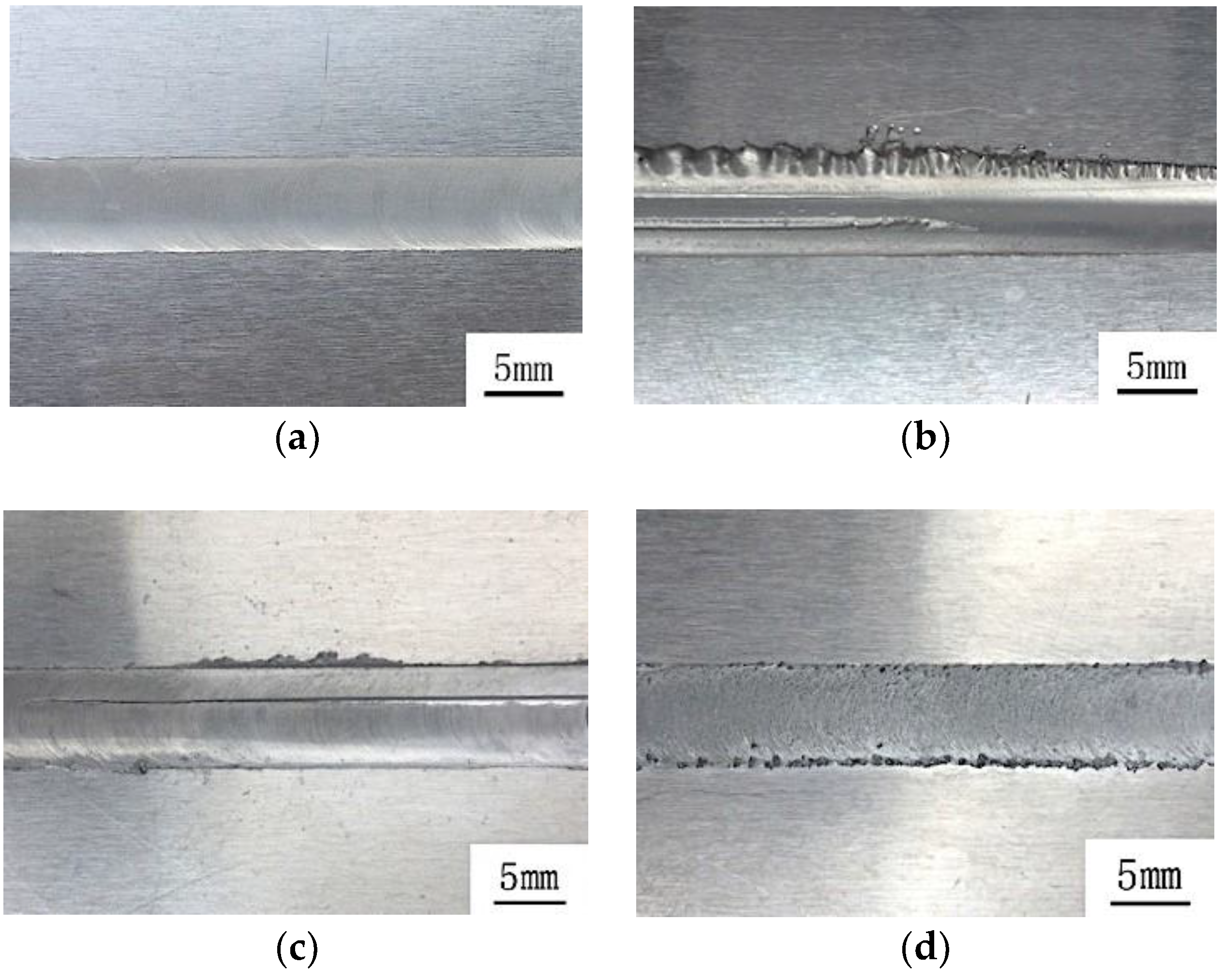
Figure 4.
Distribution of axial force with different rotation speeds.
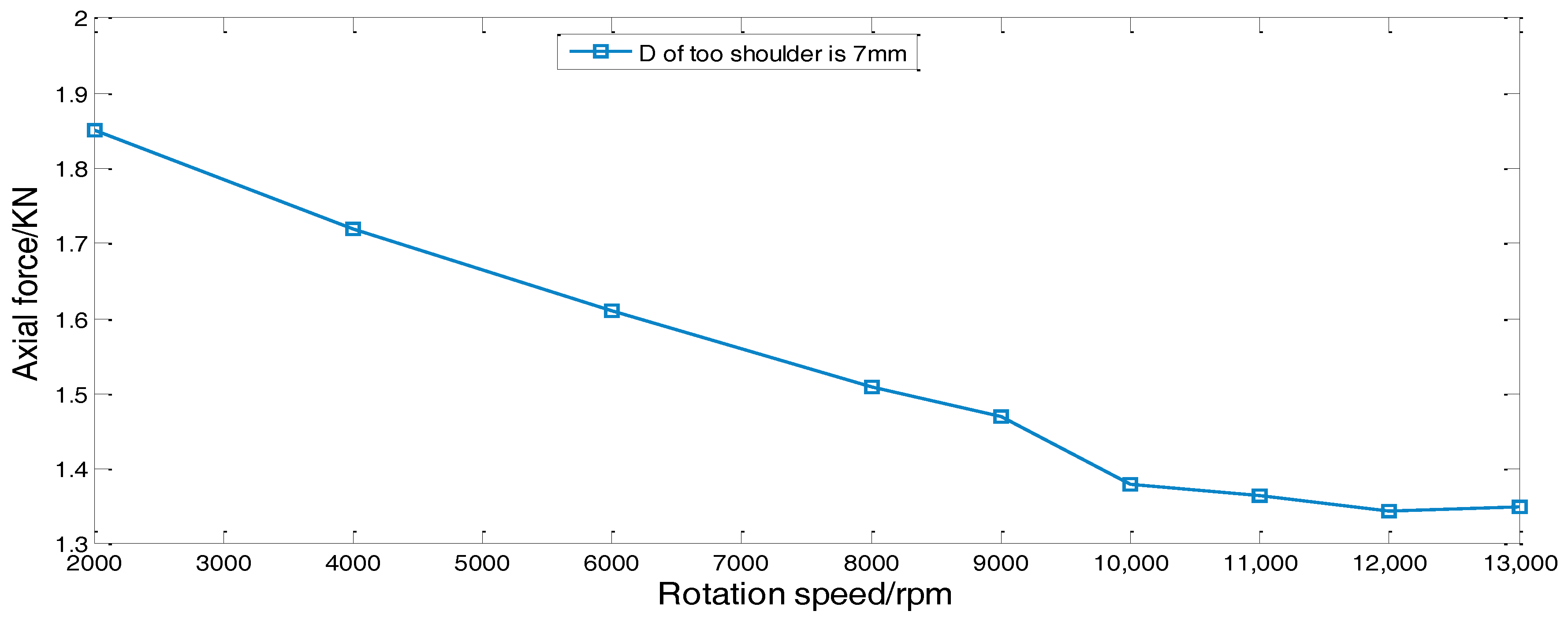
Figure 5.
Distribution of axial force during the welding process with different travel speeds.

Figure 6.
Macro-morphology of the weld: (a) W1; (b) W2; (c) W3.
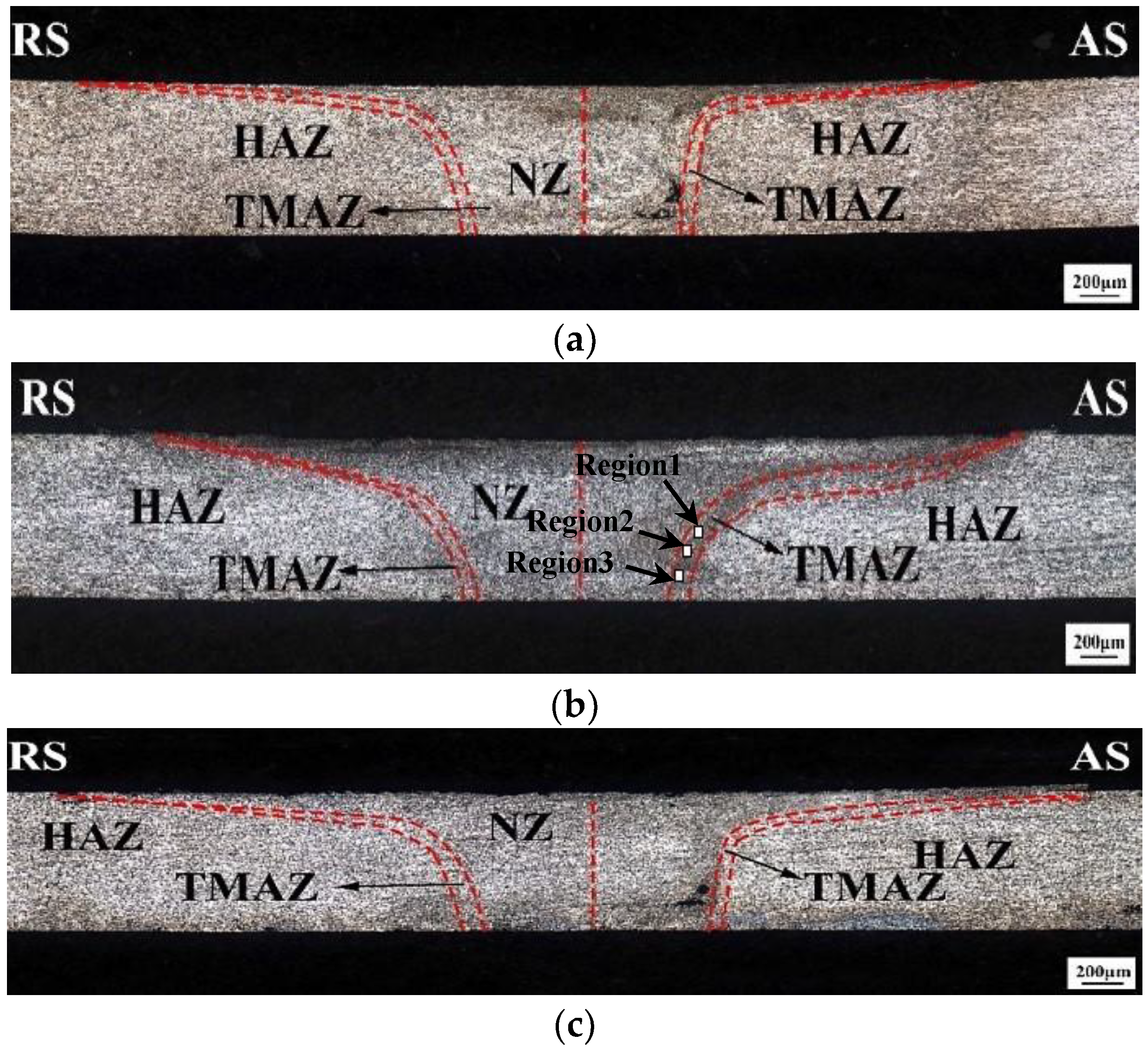
Figure 7.
Micro-area scanning of oxides. The dark field image shows the oxide, and the bright field images highlight the aluminum.
Figure 7.
Micro-area scanning of oxides. The dark field image shows the oxide, and the bright field images highlight the aluminum.
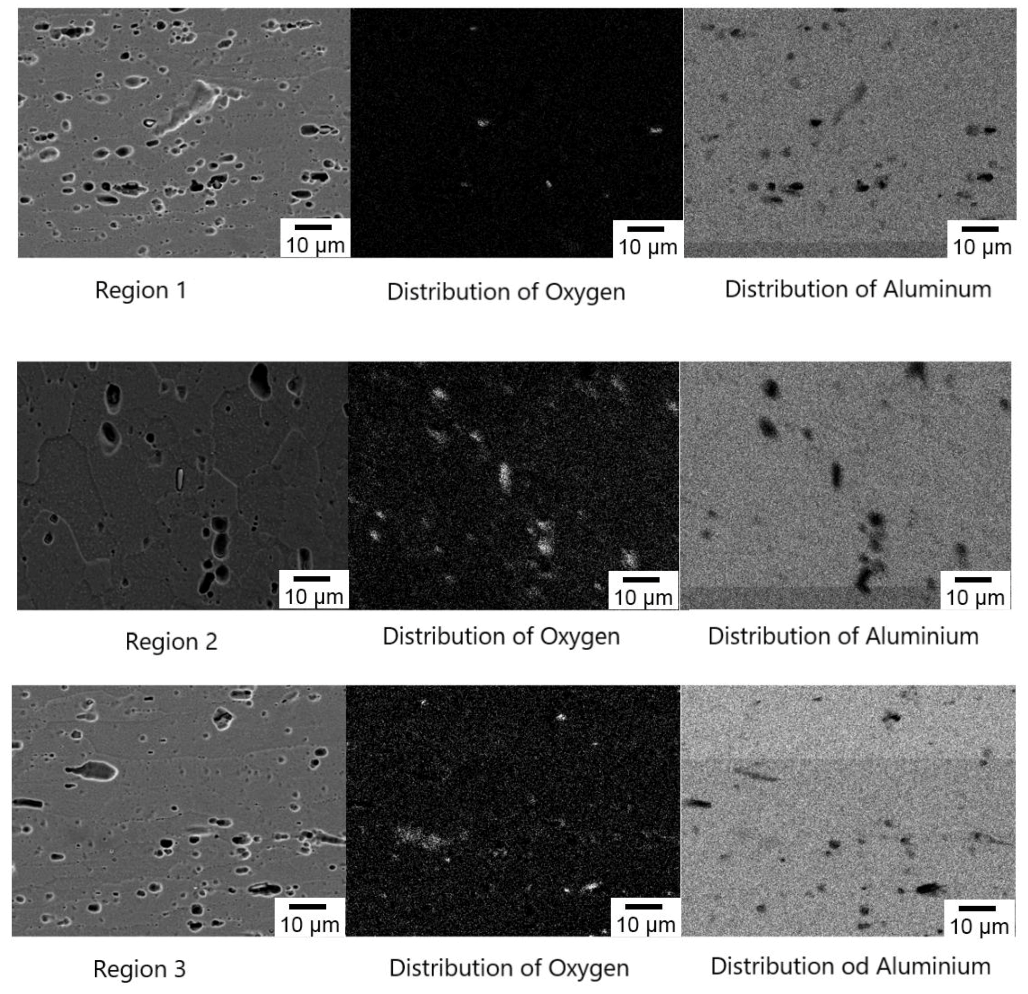
Figure 8.
Hardness distribution characteristics of cross-section: (a) W1; (b) W2; (c) W3; (d) comparison of average hardness of each zone in W1, W2, and W3 welds.
Figure 8.
Hardness distribution characteristics of cross-section: (a) W1; (b) W2; (c) W3; (d) comparison of average hardness of each zone in W1, W2, and W3 welds.
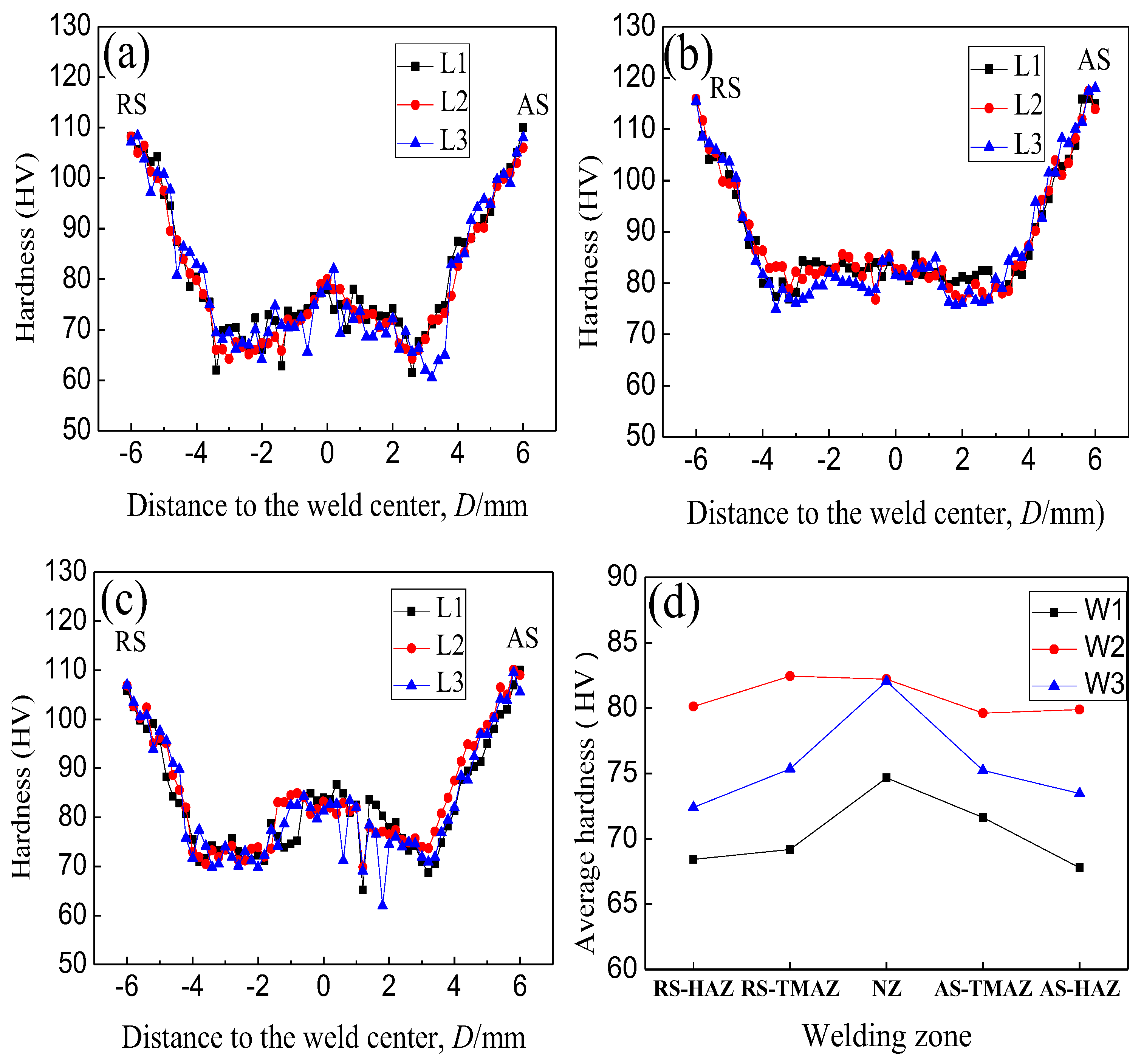
Figure 9.
The dimensions of the tensile specimen (mm).
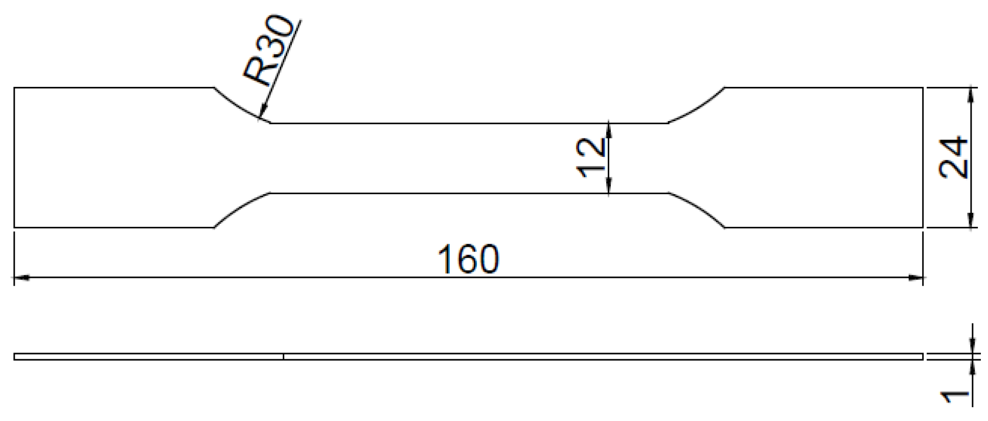
Figure 10.
Tensile curves of specimens.

Figure 11.
Fracture locations of joints.
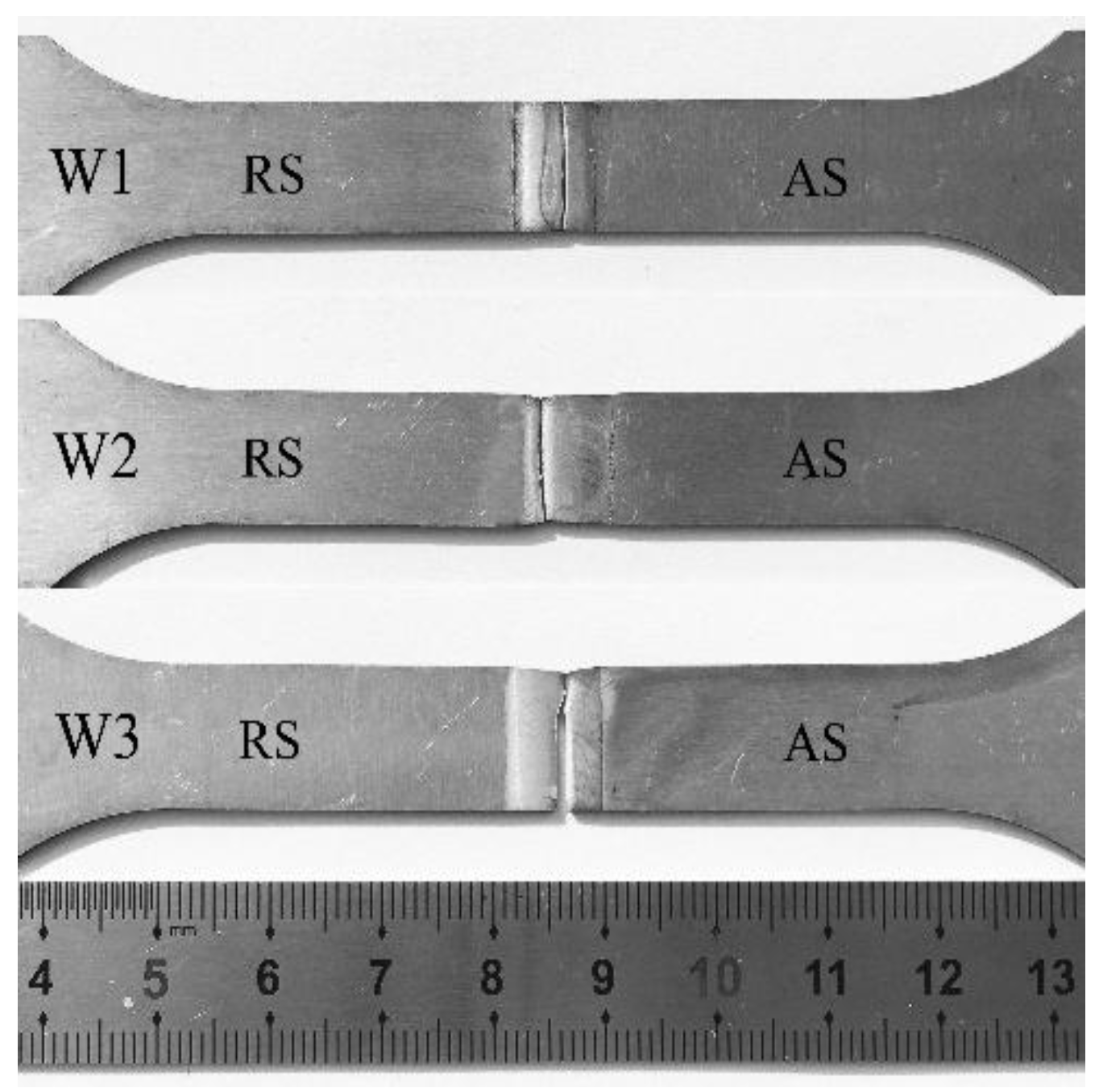
Figure 12.
The microstructure of the weld fabricated by three different FSW tools: (a) the retreating side of W1 weld; (b) the advancing side of W1 weld; (c) the retreating side of W2 weld; (d) the advancing side of W2 weld; (e) the retreating side of W3 weld; (f) the advancing side of W3 weld.
Figure 12.
The microstructure of the weld fabricated by three different FSW tools: (a) the retreating side of W1 weld; (b) the advancing side of W1 weld; (c) the retreating side of W2 weld; (d) the advancing side of W2 weld; (e) the retreating side of W3 weld; (f) the advancing side of W3 weld.

Figure 13.
OIM (Orientation Imaging Microscopy) photographs of welded joints (W2): (a) BM; (b) HAZ; (c) TMAZ; (d) NZ.
Figure 13.
OIM (Orientation Imaging Microscopy) photographs of welded joints (W2): (a) BM; (b) HAZ; (c) TMAZ; (d) NZ.

Figure 14.
Orientation distribution of 6061-T6 aluminum alloy welded joints (W2): (a) BM; (b) HAZ; (c) TMAZ; (d) NZ. Rel. (relative) frequency is the probability of occurrence of the grain boundary with various orientation angles.
Figure 14.
Orientation distribution of 6061-T6 aluminum alloy welded joints (W2): (a) BM; (b) HAZ; (c) TMAZ; (d) NZ. Rel. (relative) frequency is the probability of occurrence of the grain boundary with various orientation angles.

Table 1.
Composition of 6061-T6 aluminum.
| Chemical Composition (mass%) | ||||||||
|---|---|---|---|---|---|---|---|---|
| Cu | Si | Fe | Mn | Mg | Zn | Cr | Ti | Al |
| 0.15–0.4 | 0.4–0.8 | 0.7 | 0.15 | 0.8–1.2 | 0.25 | 0.04–0.35 | 0.15 | margin |
Table 2.
Weld surface at different travel speeds.
| V (mm/min) | 200 | 300 | 400 | 500 | |
|---|---|---|---|---|---|
| Pin | |||||
| S1 | Flash, groove | smooth (W1) | groove | groove | |
| S2 | rough | smooth (W2) | smooth | groove | |
| S3 | flash | smooth (W3) | smooth | groove | |
© 2018 by the authors. Licensee MDPI, Basel, Switzerland. This article is an open access article distributed under the terms and conditions of the Creative Commons Attribution (CC BY) license (http://creativecommons.org/licenses/by/4.0/).
Share and Cite
MDPI and ACS Style
Zhou, Y.; Chen, S.; Wang, J.; Wang, P.; Xia, J. Influences of Pin Shape on a High Rotation Speed Friction Stir Welding Joint of a 6061-T6 Aluminum Alloy Sheet. Metals 2018, 8, 987. https://doi.org/10.3390/met8120987
AMA Style
Zhou Y, Chen S, Wang J, Wang P, Xia J. Influences of Pin Shape on a High Rotation Speed Friction Stir Welding Joint of a 6061-T6 Aluminum Alloy Sheet. Metals. 2018; 8(12):987. https://doi.org/10.3390/met8120987
Chicago/Turabian StyleZhou, Yang, Shujin Chen, Jiayou Wang, Penghao Wang, and Jingyu Xia. 2018. "Influences of Pin Shape on a High Rotation Speed Friction Stir Welding Joint of a 6061-T6 Aluminum Alloy Sheet" Metals 8, no. 12: 987. https://doi.org/10.3390/met8120987
Note that from the first issue of 2016, this journal uses article numbers instead of page numbers. See further details here.