1. Introduction
Surface composite (SC) fabrication via friction stir processing (FSP) has become popular over the last decade as it is a clean process and capable of developing superior microstructure and properties. Apart from other materials, aluminum alloys are largely used for SC fabrication by employing various ceramics/hard particle(s) in powder form to provide reinforcement in the ductile interior [
1,
2]. There is a constant urge to improve mechanical properties such as hardness, wear resistance and corrosion resistance in general and strength in particular, in aluminum alloys to further enhance its high specific strength and other associated mechanical properties. Age-hardenable aluminum alloys such as 7xxx series alloys are among the strongest aluminum alloys. Surface composite fabrication may be an attractive approach to further strengthen these alloys. In precipitation-hardenable alloys, aging imparts maximum allowable strength and aging is the final treatment. Any further treatment of age-hardened alloys usually leads to drop in strength due to Ostwald ripening. If suitable treatment including SC fabrication coupled with/without another stage of aging can provide further improvement in the strength, it may lead to great weight savings. This is the main driving force for the present work in which single pass FSP was employed to fabricate SCs on 7xxx series aluminum alloy. The FSP is recognized as a clean process mainly because it is a solid state fabrication technology and it retains the value-additions of primary processing. In addition, it uses significantly less energy, and the energy being supplied is fruitfully utilized in material properties enhancement. The process is also free from effluent emanation.
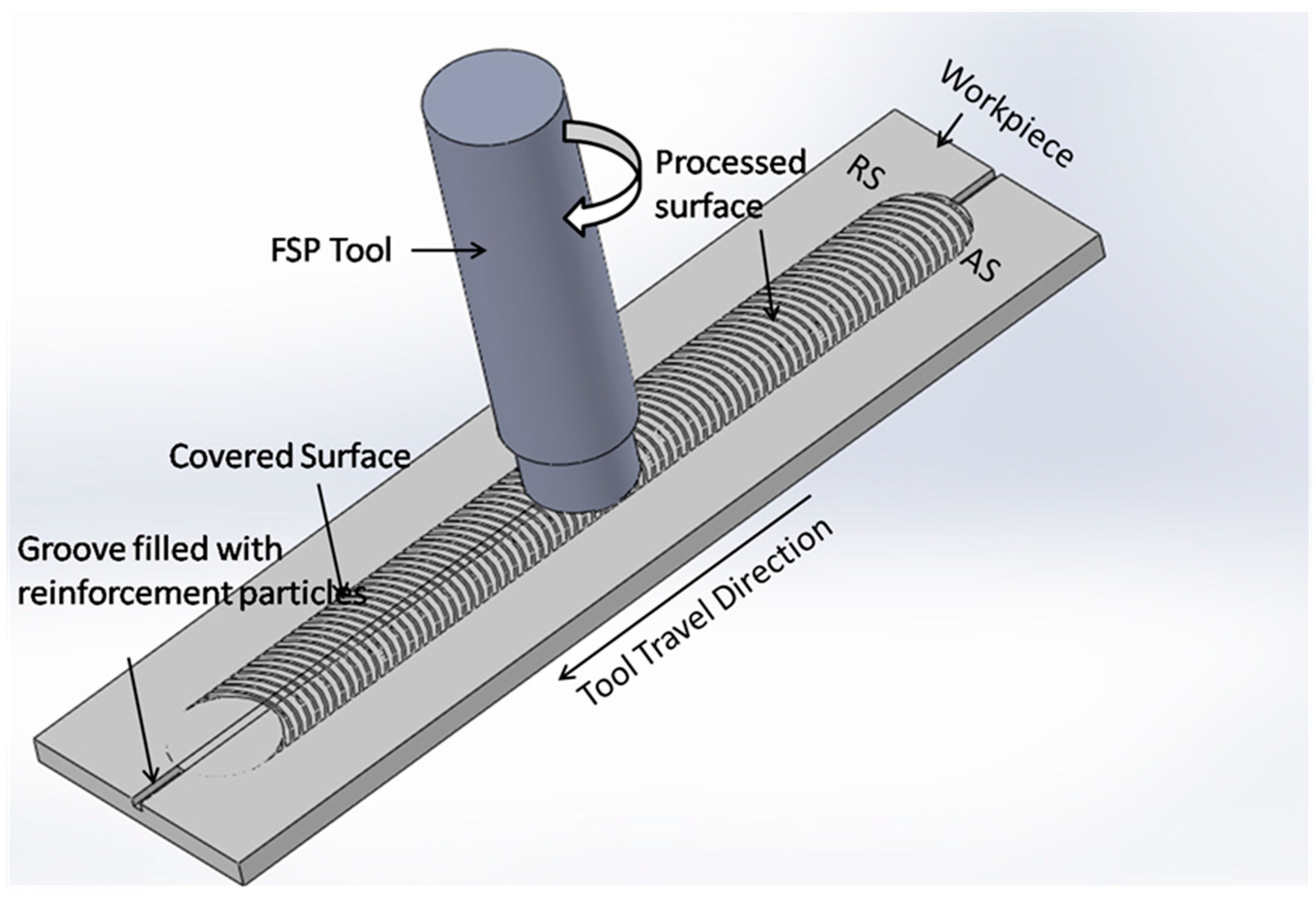
To fabricate SCs, the reinforcement particles are first preplaced in the matrix material (i.e., the base material) through a special FSP tool. The tool, while rotating, is inserted in the base material (BM), and after insertion it is traversed in the processing direction (as shown in
Figure 1). Friction between the tool’s shoulder and BM surface generates heat, which softens the material which is present under the shoulder. The rotation coupled with traversing action of the tool mixes preplaced reinforcement particles in the matrix material through stirring action. During stirring, the stirred material is consolidated at the trailing edge of the tool to create processed zone. In this way, the entire surface can be processed by rastering the tool translation [
3,
4].
7xxx (Zn-Mg-Cu Al-alloys) is an age-hardenable high strength aluminum alloys series. It is extensively employed in structural application in aerospace, aircraft and military sectors [
2,
5]. These alloys are commonly used in T6 and T7XX treated conditions. The T6 treatment imparts peak strength and T7XX treatment imparts high resistance to stress corrosion cracking (SCC) while simultaneously sacrificing some strength [
6,
7]. AA7050-T7451 aluminum alloy typically finds applications in fuselage frames, bulkheads, wing skins, etc. due to its good strength, toughness and crack resistance [
6,
8]. The improvement in mechanical properties in SCs also depends very strongly on factors such as grain refinement and homogeneity of distribution of hard phase. In the case of age-hardened alloys, the enhancement of strength is even more difficult. This is mainly because the strengthening imparted by the minute, dense and homogenously distributed hardening precipitates overplays all other strengthening mechanisms. SC fabrication via FSP produces ultrafine grains and distributes reinforcement particles in the processed region. Improvement in properties in age-hardened alloys can be achieved only when distribution of particles is achieved without over-aging; otherwise, it may even result in the drop in strength. Thus, SC fabrication of high strength precipitation hardened 7xxx alloys is challenging. Furthermore, limited literature is available on surface composite fabrication through FSP on 7xxx series of aluminum alloys [
2,
9,
10,
11,
12].
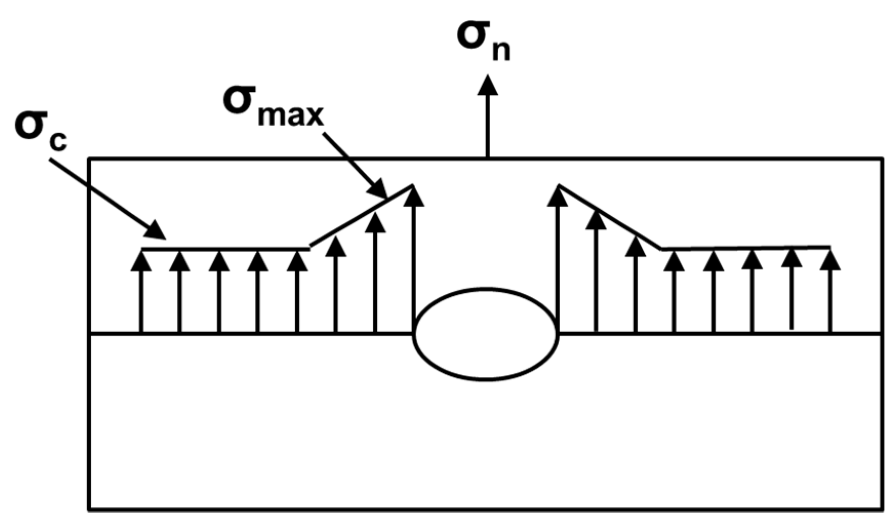
Although much work on SC fabrication in the area of reinforcement particle distribution has been reported, most studies report parametric investigation and effect of multiple passes. Furthermore, most studies performed on SC fabrication on Al-alloys are on non-age-hardenable alloys. Incidentally, multi-pass FSP may not be an effective strategy for strengthening of age-hardened alloys as heat input during every pass promotes chances of ripening. Understanding of the mechanism of distribution of hard phase in the substrate is still evolving. The dispersion and distribution of particles greatly depends on the effectiveness of stirring action. Under conditions of lack of homogeneity of distribution, considerable portion of packed particles remains accumulated at/near original pre-placement. Particle accumulated region(s) act as discontinuities which share little in-service load and reduce the effective load bearing area of the entire cross-section. It also acts as stress raiser and leads to stress concentration. Moreover, such in-homogeneities make the testing of fabricated SCs more complex, as basic principles of testing require material to be homogeneous.
Discontinuities caused by particle accumulation produce stress concentration in the vicinity of discontinuity. Exact theory of mechanics shows that the peak intensity of stress concentration “
” exists (as shown in
Figure 2) at the extremities of the discontinuity and it can be as high as three times the value of nominal stress “
” for a circular discontinuity. For a noncircular discontinuity (such as the elliptical one typically shown in the figure), magnitude of the stress concentration depends on the length of major and minor axes. The value of “
” can be much higher for elliptical discontinuities or for those with sharp corners [
13,
14,
15]. In any case, a sudden discontinuity adversely affects the strength in elastic range and when the part is subjected to variable loads. If a small discontinuity in the form of accumulation exists, the fabricated SC may be weakest in the vicinity of discontinuity and may fail even though rest of the material may be much stronger. The homogeneous particle distribution without accumulation is, thus, most important.
Interestingly, whereas the material movement has been considerably investigated for friction stir welding (FSW) [
16], the same is not true for SC fabrication via FSP [
9,
17,
18]. Material movement, in the case of SC fabrication, is quite different because of heterogeneous makeup of the material being stirred. To obtain better particle distribution, researchers have used multi-pass FSP as a general strategy [
9,
17,
18,
19]. However, multiple passes raise the heat input of processed zone (PZ) which adds to over-aging woes, aiding solutionizing and coagulation of precipitates, which may drastically reduce the strength of age-hardened matrix based SCs. The increased net energy input due to multiple passes also undermines the very essence of energy efficacy of this clean process. This strategy is also time and energy consuming and often may not yield desired enhancements in properties of age-hardened alloys [
20]. Thus, use of multi-pass as a general strategy to obtain homogeneous distribution may not be a wise alternative, especially for age-hardened alloys. Instead, efforts should be directed to evolve an understanding on exactly how major process parameters engage with the particle distribution in the material being processed. Studies of such kind are scarcely reported. Present article makes an attempt to investigate the manner in which FSP process parameters engage with the heterogeneous mix of material (age-hardened BM and reinforcement particles) being stirred through single pass FSP. In addition, since the individual FSP parameters may have contradicting effect of the response, a unique compound input parameter represented as “unit stirring”, which relates to responses, is defined. A new three stage particle distribution and novel indices for measures of effectiveness of these stages in single pass FSP is also proposed. Results and inferences are demonstrated through fabrication of AA7050/TiB
2 SC.
3. Results and Discussion
Simultaneous tool rotation and traversing is responsible for stirring and net material movement. SC processing rate can be assessed in terms advancement of tool per revolution and can be estimated by the ratio of traversing speed “T” to tool rotation “R” (i.e., T/R). Typically, in simple FSP (i.e., without reinforcement), tool moves the material ahead layer by layer, and deposits it behind to replenish the space created by the advancing tool. This layer by layer movement is accomplished through a series of stick and slip actions between the layers and tool. However, in the case of SC fabrication, the reinforcement is in the form of a mix of matrix material and unbinded, loose and discrete particles. Thus, the movement of unbinded particle may be sluggish, whereas the matrix material may move on. How sluggish is the movement of reinforcement particles, however, depends on several factors such as shape and size of particles, friction characteristics, conditions of temperature, flow stress, etc. Given this situation, if the processing rate is high, it may be possible that the reinforcement particles may slip more, stick less and hence may not move with the same pace as that of the matrix material. At slower processing rate, the material will be stirred more as number of unit traversing of tool per unit revolution will be less. Under the conditions of prevailing processing rates, by the time the shoulder traverses a distance equal to shoulder diameter, the reinforcement particles may have been subjected to several repeated actions of stirring, causing the particles to first spread, then mix and finally disperse in fabricated SCs.
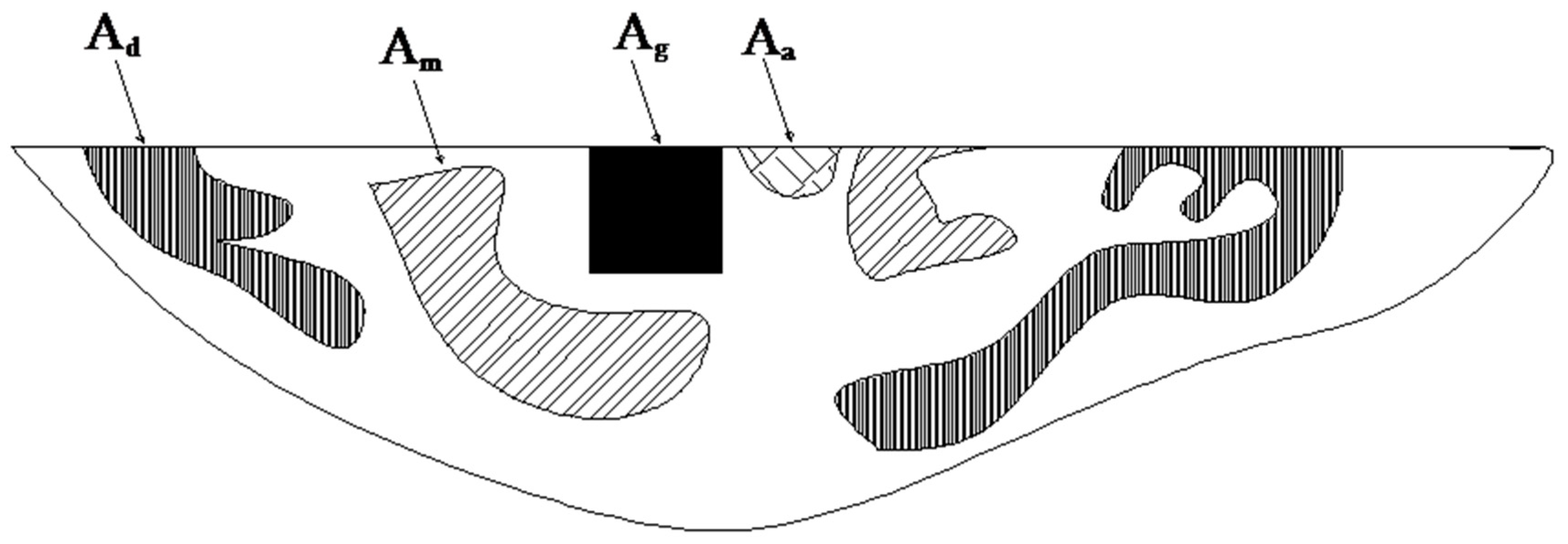
If reinforcement particles did not remain accumulated in place but moved effectively, homogeneous distribution can occur in three consecutive stages: (a) spreading; (b) mixing; and (c) even or homogeneous distribution or dispersion. During spreading, the particles get scattered (yet remain accumulated closely) without adequate mixing with BM. In mixing stage, particles, although mix with BM, remain too closely packed and reinforcement–BM bonding is weak. In final stage, the particles become intimately mixed with BM as well as well dispersed, have intimate bonding with the matrix and the mixture is even and homogeneous.
Depending on processing rate, regions that undergo these stages of distribution are formed and are schematically shown in
Figure 4. The outline encompassing all zones is the entire processed zone (PZ, with the area of PZ specified as A
pz) which has been processed by the tool. There also exists region where no reinforcement could reach. This region, however, has been subjected to simple FSP and undergoes grain refinement. Attempts of tool during stirring subject the particles, in succession, to spreading, portions of spread particle to mixing and mixed particles to dispersion. In accumulation (or spreading) region, the particles do not undergo subsequent stages of mixing/dispersion, because tool’s sustained efforts were not available as it has moved ahead without adequate stirring leaving behind particles to remain spread only. Subsequent actions of tool in the mixed regions actually result in increasing the extent of spreading, causing more even distribution.
Ideally, for perfectly dispersed SC, there should be no accumulation and entire PZ should have homogenous distribution of reinforcement. In practical situation, some regions may always exist where no reinforcement particle is present, although this region undergoes simple FSP. In the present investigation, these regions were visible. The areas of each region were measured and their values are shown in
Table 3.
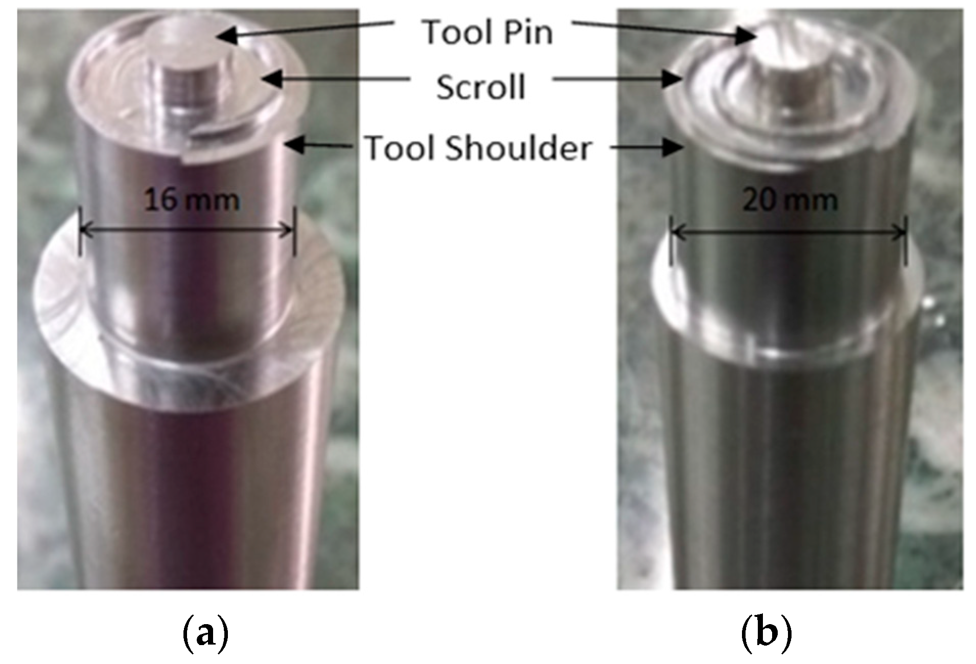
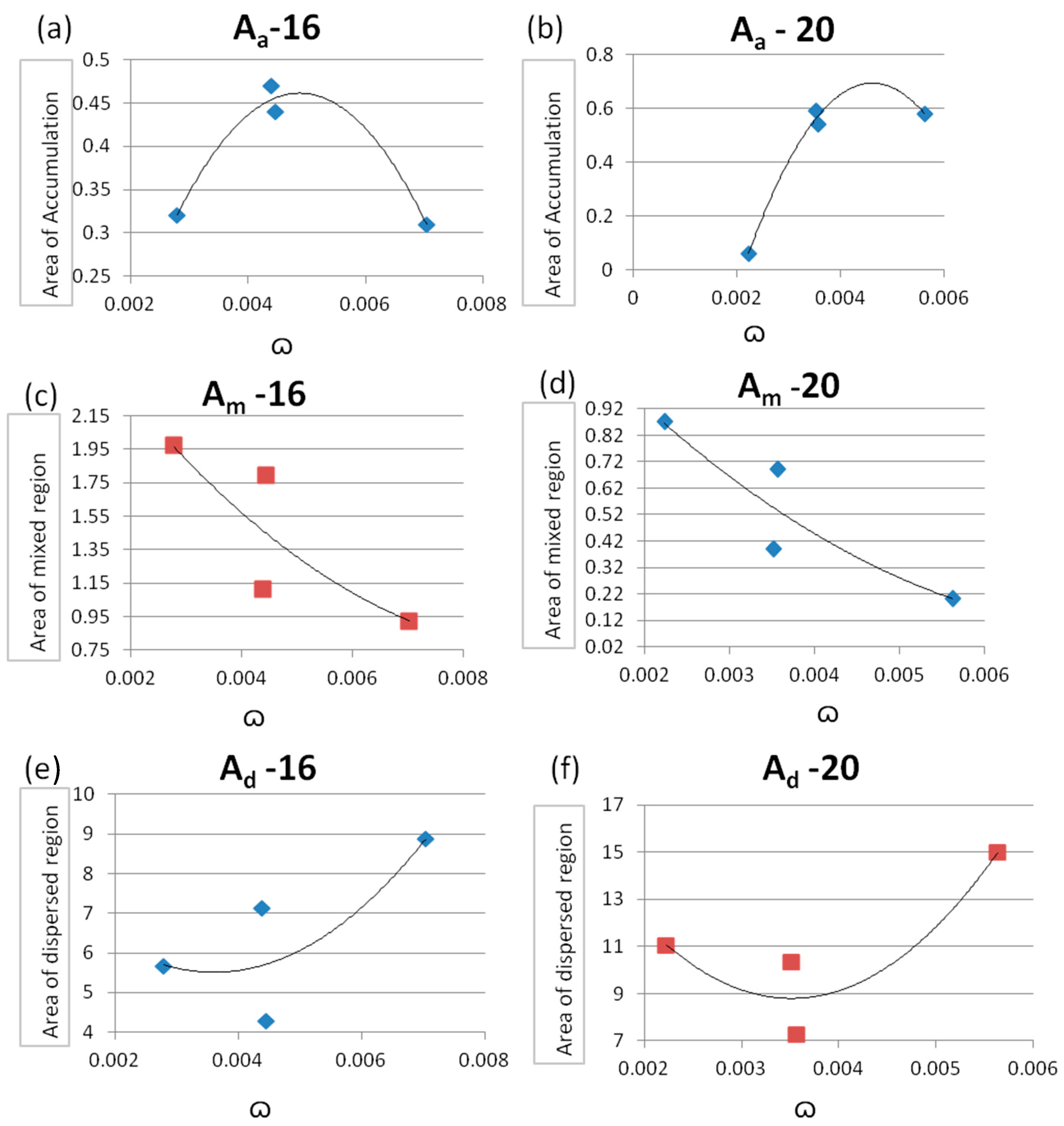
The effects of derived parameter “
” investigated for two different diameters, i.e., 16 mm and 20 mm, and areas of zones pertaining to characteristic stages have been plotted and the same is shown in
Figure 5. The results show that the nature of plots of same response for the different diameters possesses good symmetry.
This is to note that the most desirable response is the area of dispersion zone (i.e., A
d as already defined in
Figure 4) and it follows an increasing trend while rest of the two responses follow a decreasing trend with the increase of the value of “
”. This is a useful inference to attain high degree of distribution in a single pass FSP operation during SC fabrication.
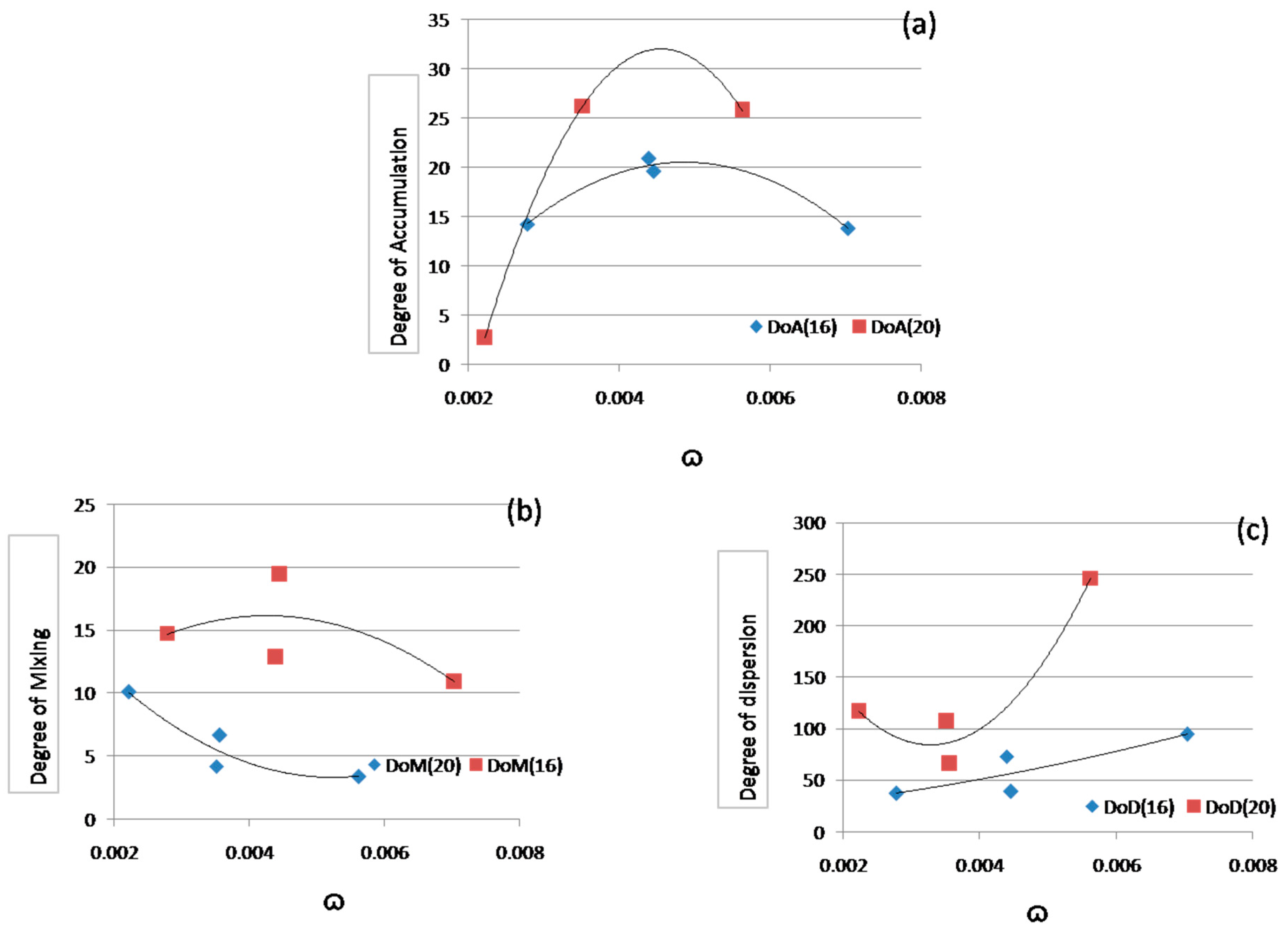
Further, the estimation of extent of particle distribution during each stage can be accomplished by three indices: degree of accumulation (
Da), degree of mixing (
Dm) and degree of dispersion (
Dd).
Da is proposed to be defined, with respect to area of cross section of groove (
Ag) in which the powder was initially packed, through a function given in Equation (1):
where
Aa is area of accumulated region.
During SC fabrication accumulation should not occur; the mixing regions is undesirable and should be as small as possible; and dispersion should be maximum. Thus, the proposed
Dm is defined as given in Equation (2):
where
Ap is the area of simple FSPed region where no reinforcement has taken place. The proposed
Dd is defined as per function given in Equation (3):
Typically, the extent of all three indices bears close relationship with FSP process parameters. The values of these indices are estimated and are given
Table 4.
The estimated indices are also plotted against unit stirring for the two selected shoulder diameters, i.e., 16 and 20 mm. These plots are given in
Figure 6. Results from the experiments were also analyzed through macro- and micrographs taken from each region to corroborate the morphology and particle densities and pattern of distribution in the characteristic stages of distribution.
The plots given in
Figure 6a–c indicate that the variation of all three indices is consistent for both diameters. In addition, an increase in unit stirring results in better dispersion, which is desirable; further, it also causes undesirable indices to reduce. This gives valuable input to choose appropriate values of process parameters which yield maximum desirable response in the single pass FSP for SC fabrication. It is worth mentioning that an increase in shoulder diameter, increases net material movement and heat input. Under these circumstances, the nature of matrix–reinforcement interface changes, which in turn results in the change in all three indices for different shoulder diameters.
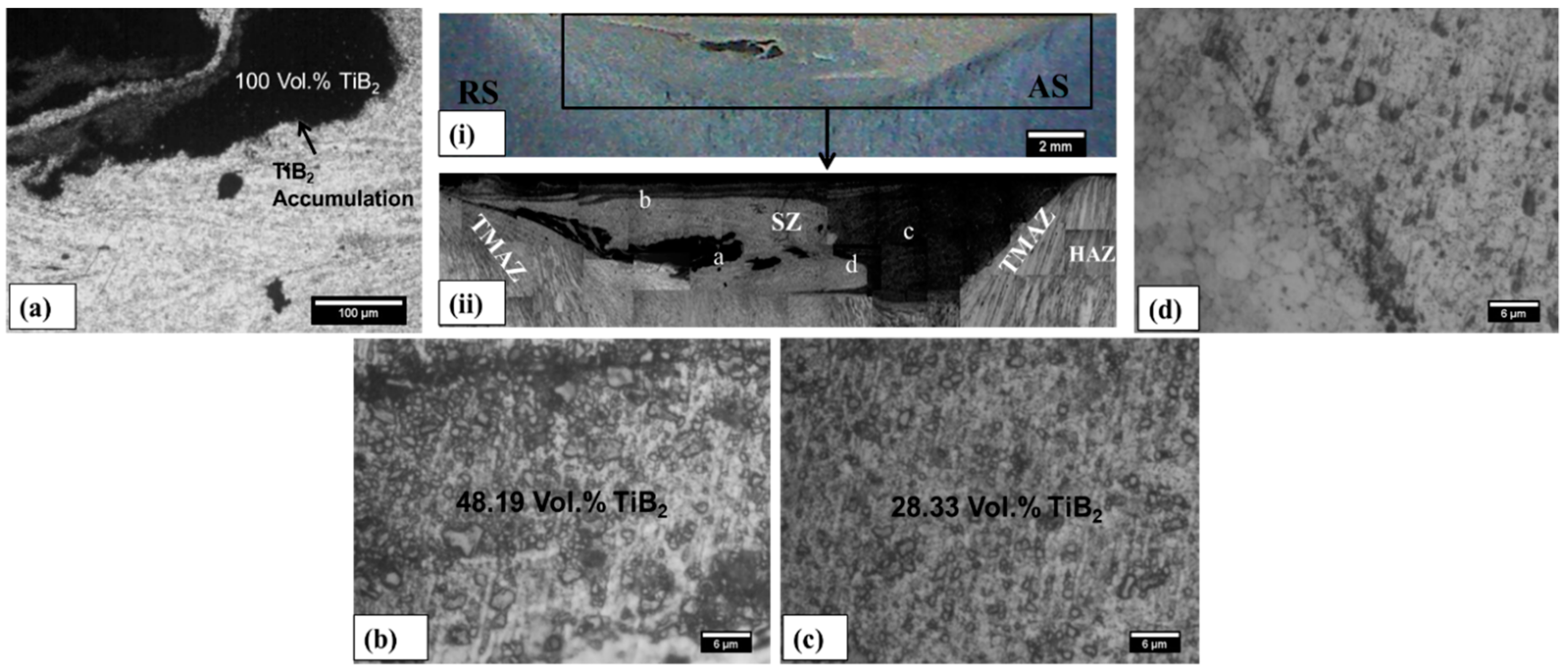
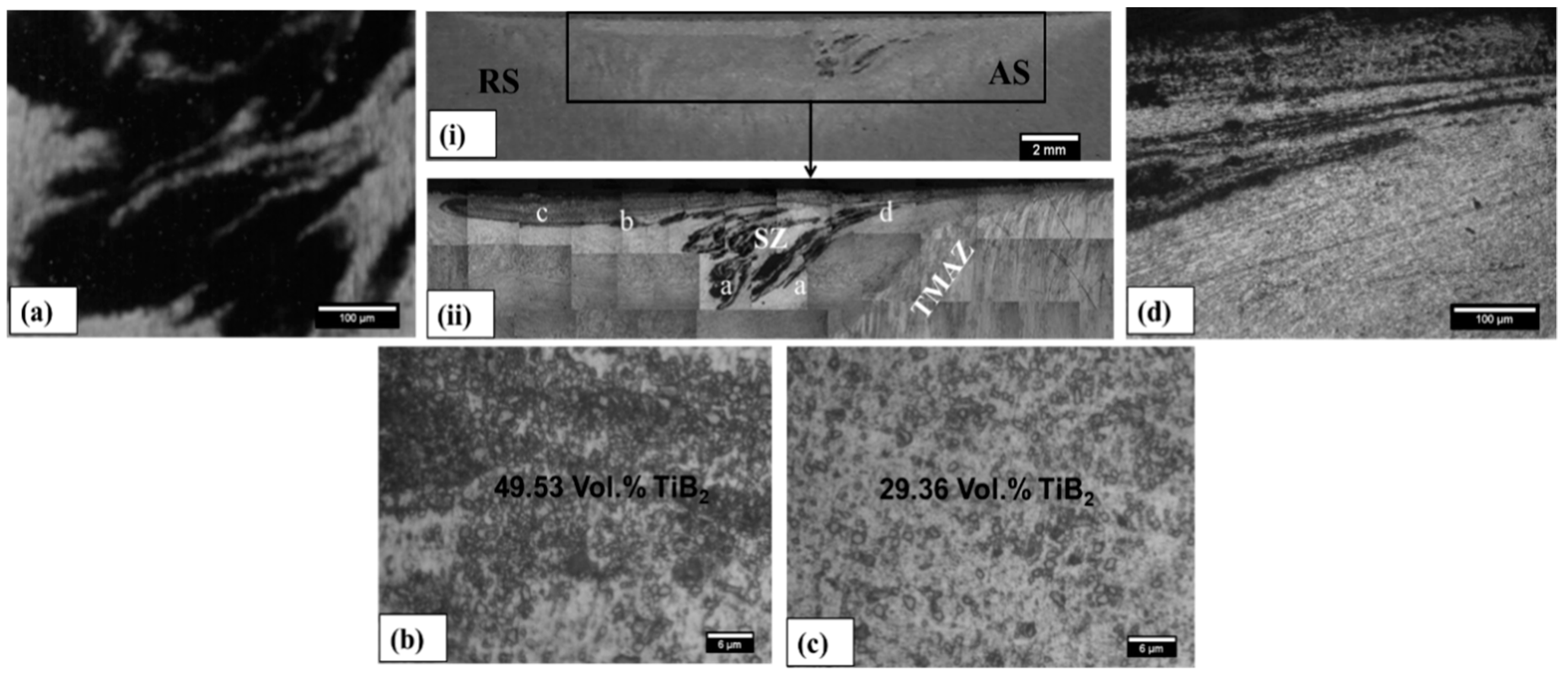
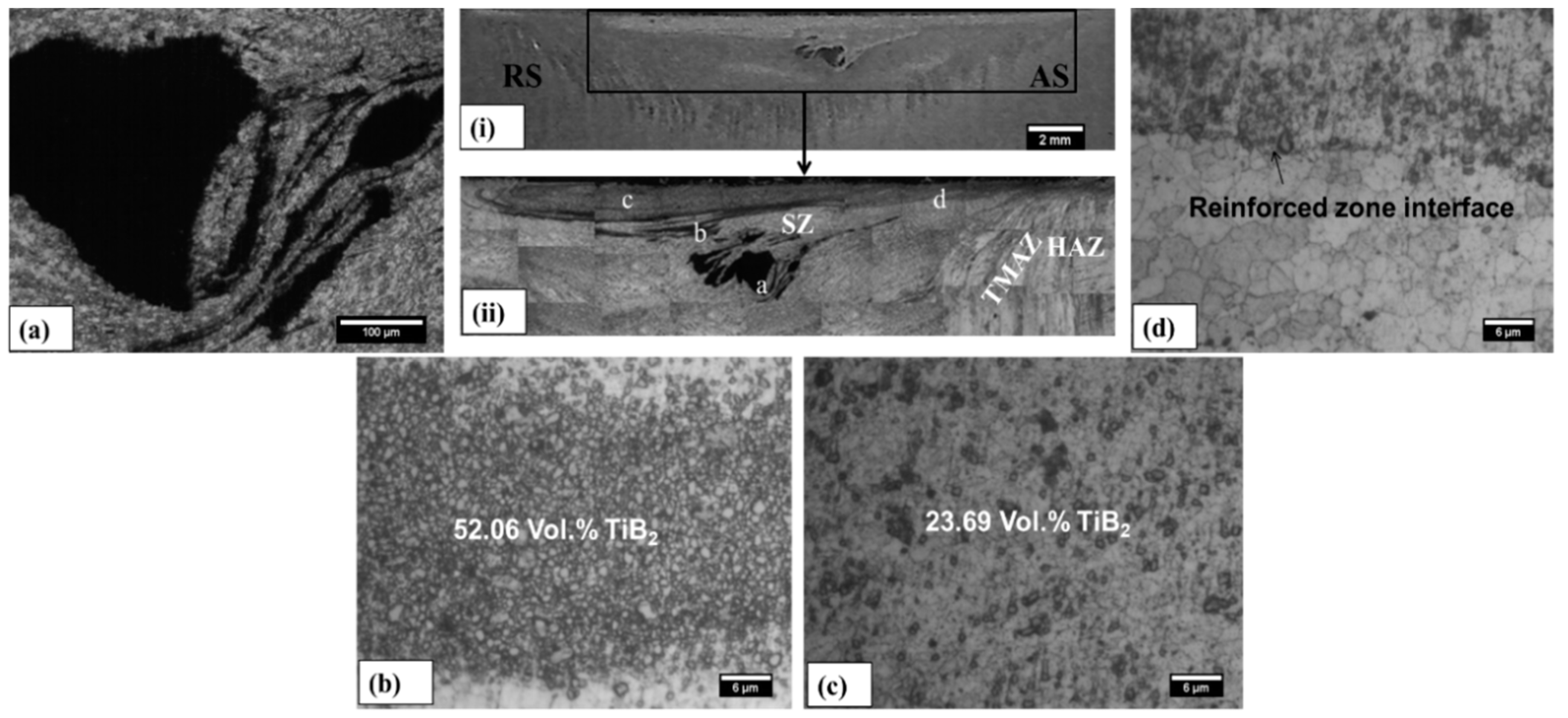
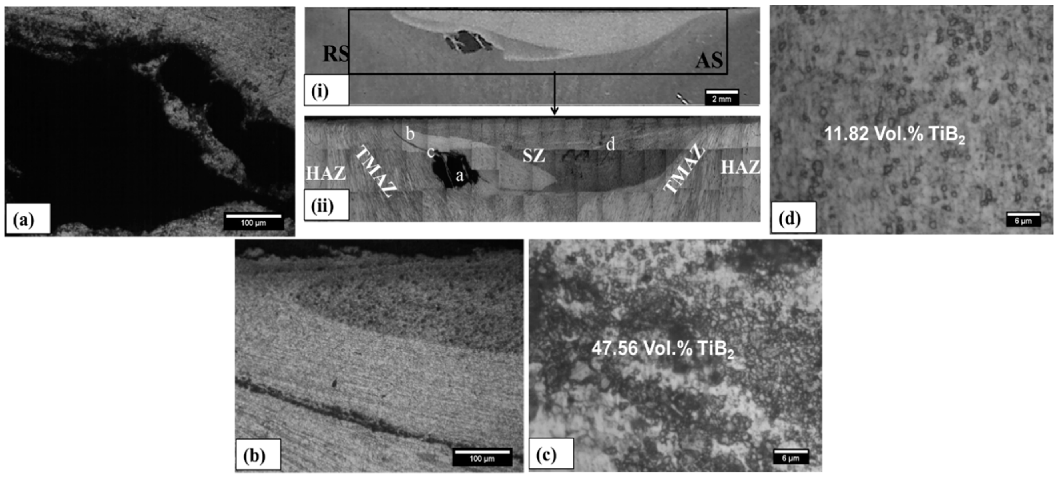
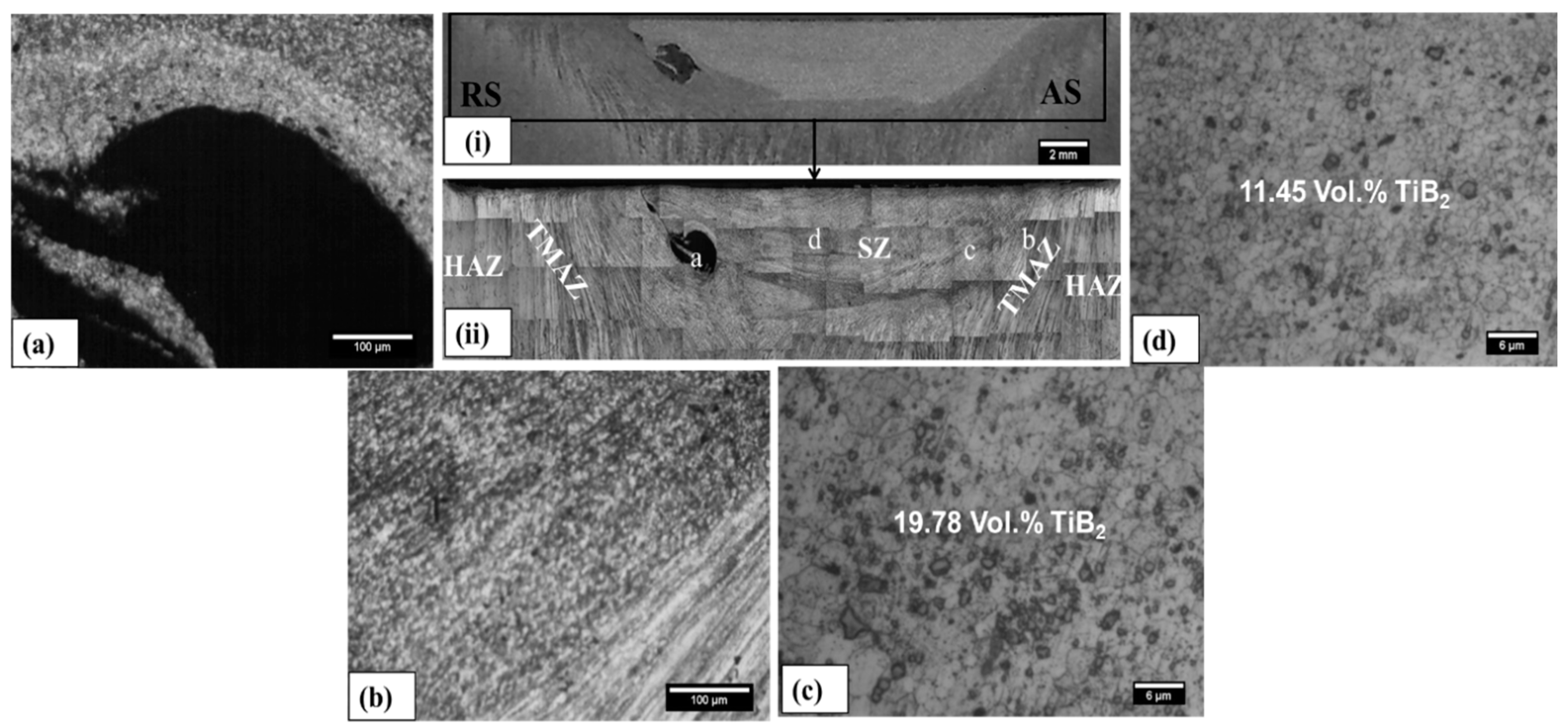
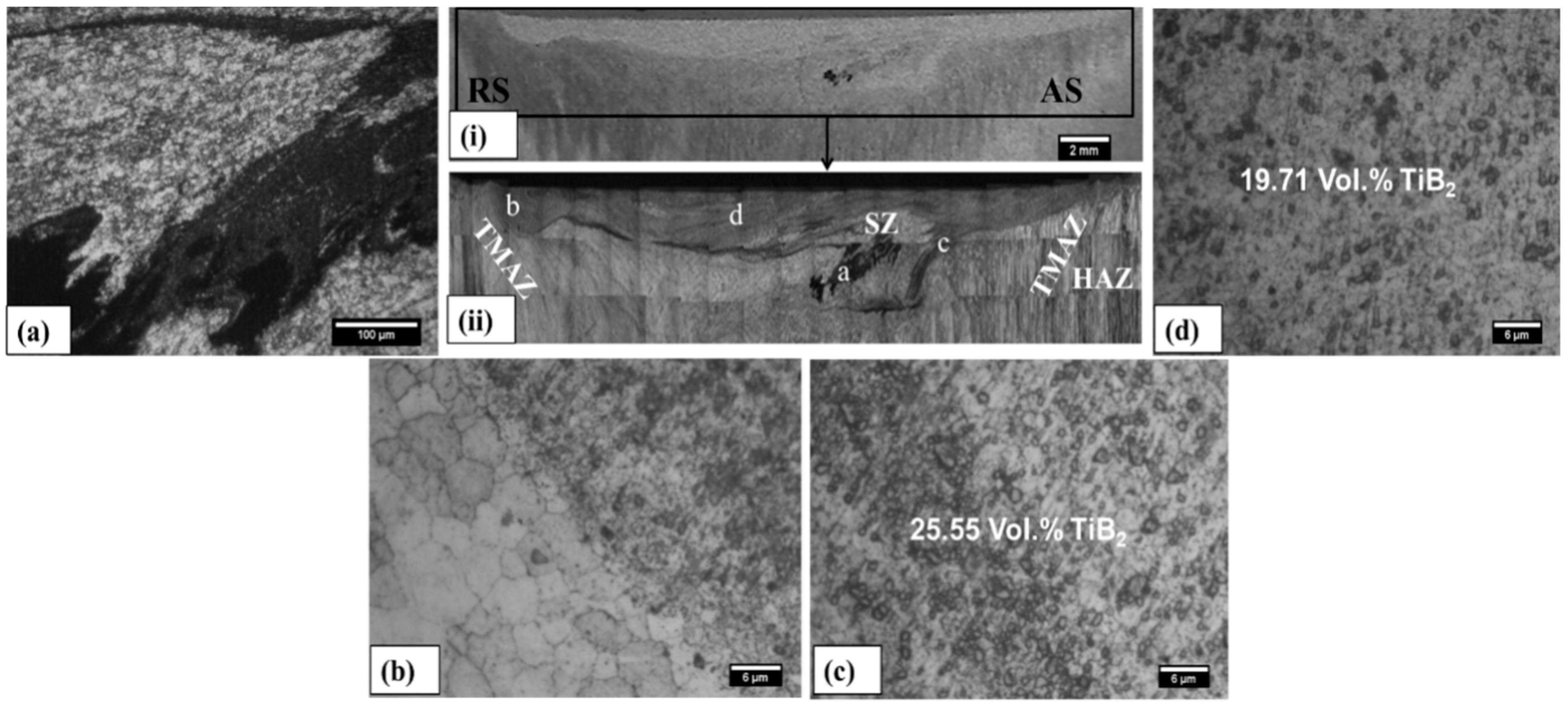
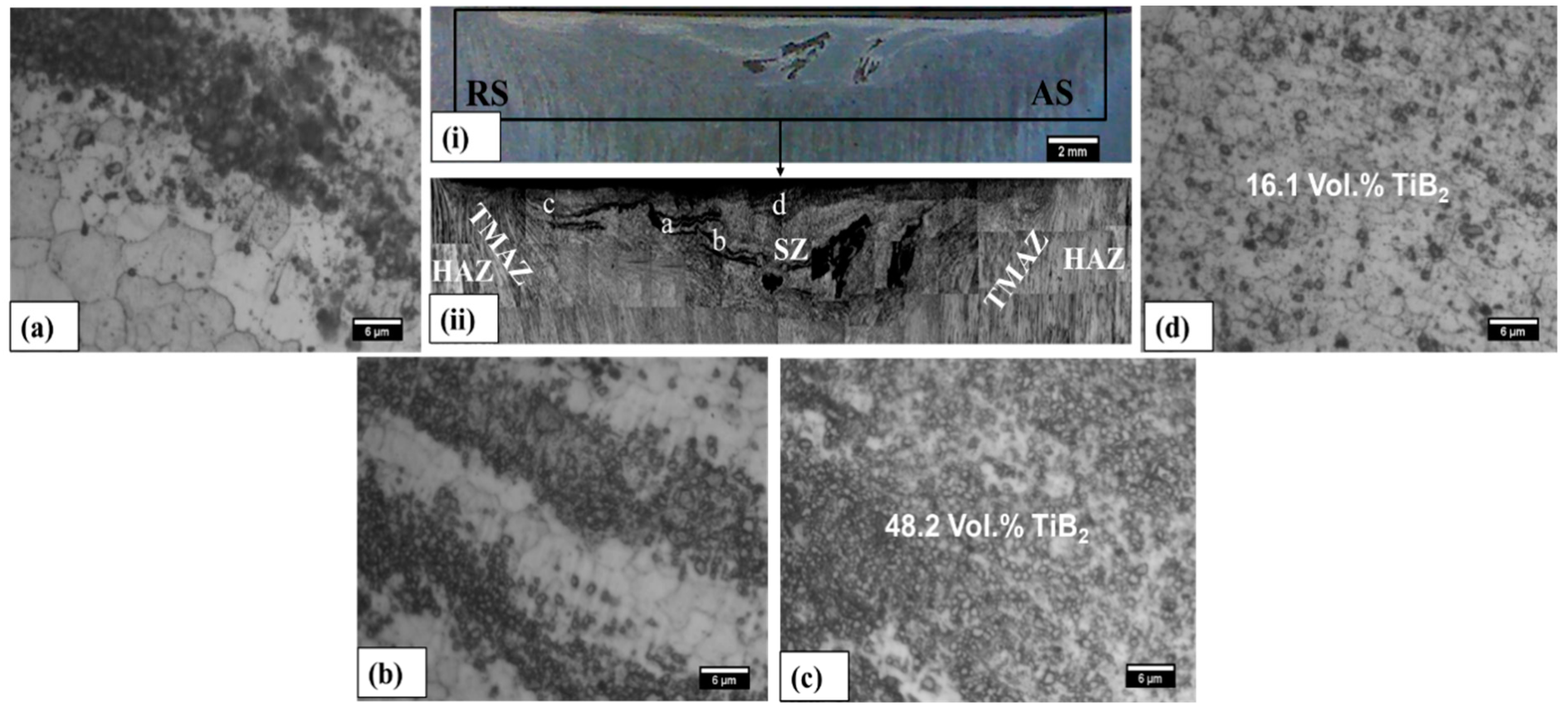
Macro- and Micro-Structure
The Macrograph and micrographs taken from the transverse section of the SC samples are shown in
Figure 7,
Figure 8,
Figure 9,
Figure 10,
Figure 11,
Figure 12,
Figure 13 and
Figure 14 (i and ii). The dark grey and black portion in
Figure 7,
Figure 8,
Figure 9,
Figure 10,
Figure 11,
Figure 12,
Figure 13 and
Figure 14 (ii) represents the area of reinforced zone (A
r) of the fabricated composites. The characteristic regions, namely accumulated, mixed, and dispersed regions, are clearly visible in the reinforced zone of the samples where a particular region is present. Detailed microstructure of various regions shown in the macro-scale views of
Figure 7,
Figure 8,
Figure 9,
Figure 10,
Figure 11,
Figure 12,
Figure 13 and
Figure 14 (i,ii) is given in
Figure 7,
Figure 8,
Figure 9,
Figure 10,
Figure 11,
Figure 12,
Figure 13 and
Figure 14 (a–d). In samples 1–4, 7 and 8, the accumulation (agglomeration) of particles is observed close to the middle in the stir zone (SZ), as shown in
Figure 7,
Figure 8,
Figure 9 and
Figure 10, 13 and 14 (i and ii). The agglomeration is observed on retreating side (RS) of the SZ in Samples 5 and 6 (
Figure 11 and
Figure 12). The agglomeration or accumulation occurs as a result of inadequate material flow in processed region. The main reason for the inadequate flow, which results in agglomeration, is the insufficient heat input due to undesirable FSP parameter combinations and resistance offered by reinforcement [
19,
21,
22].
In this research work the processing was performed in position control mode and the plunge for kept constant. At a fixed plunge and considering the frictional characteristics for work and tool material combination to remain constant, the heat input during processing would largely depend on the ratio of tool rpm and traversing speed (T/R ratio) and on shoulder diameter. Least amount of agglomeration of particles was found in sample number 7, which may be attributed to sufficient heat input to cause efficient material flow in processed region. The density of TiB2 particles in various regions (given in respective figures) is not same in all the regions of PZ. The distributed particles are densely packed in the mixed region; whereas, in dispersed region they are sufficiently sparsely distributed so as to have good particle-matrix bonding.
Particle accumulation acts as stress raiser and seriously affects properties of the fabricated SCs. Mixed regions may also contain clusters of particles and may cause poor bonding with substrate material. It is necessary to achieve good bonding of reinforcement particles with the substrate effective and homogeneous particle dispersion in processed region. It is worth mentioning that the relationships between process parameters and characteristic processed regions help in avoiding the detrimental effects of these discontinuities.
Achieving uniform particles distribution has been a very critical issue in SC fabrication through FSP. Sustained efforts have been directed towards achieving uniform particles distribution to strengthen the material by utilizing various strategies [
9,
17,
18,
19,
22]. In most of the available literature, it is improved by applying multiple FSP passes along the same direction of processing or reversing the direction of AS and RS [
9,
17,
18,
19]. Every pass reduces the accumulation of particles from spread region, and more evenly disperses the particles from mixed region. This is due to re-stirring actions of the tool, which results in homogeneous distribution of particles. Recently, Sharma et al. (2016) applied strategies such as variation in tool speeds, offset and pin diameter to achieve better distribution of SiC particles on the AA5083 by utilizing multi-pass processing technique [
22]. However, every pass also simultaneously increases the processing time and net energy input, which undermines the very essence of this clean technology.
Furthermore, multiple pass FSP also requires a lot of time in setup changes. Often, flash, thinning and distortion may require substrate to be machined/corrected before being processed by subsequent passes apart from additional energy in every pass [
9]. In the case of age-hardened alloys, multi-pass strategy may even prove counter-productive, as it may lead to weakening rather than strengthening. The weakening is associated with Ostwald ripening of the strengthening precipitate [
19]. Above all, without understanding the mechanism of particle distribution, impromptu employment of multiple passes is not the best approach. It will be highly useful to establish an understanding on how the particles move during stirring and how the particle movement relates to process parameters. Often, the effects of important FSP parameters is contradictory; consequently, a unified/compound parameter such as that derived in the present study (i.e., unit stirring) can prove to be very useful.
The proposed derived parameter, i.e., unit stirring, is a novel single input parameter that relates effectively with all the characteristic responses (accumulation, mixing and dispersion) and also suitably controls the indirect responses, i.e., heat input and plastic deformation, thus significantly helps in predicting the overall FSP process during single pass SC fabrication. Unit stirring also guides in selecting the primary FSP parameters to achieve better distribution in a single pass.

 ,
, 


