Article

Enhanced Corrosion Resistance of Ultrafine-Grained Fe-Cr Alloys with Subcritical Cr Contents for Passivity

Department of Mechanical Engineering, Doshisha University, Kyoto 610-0394, Japan
*
Author to whom correspondence should be addressed.
Metals 2018, 8(3), 149; https://doi.org/10.3390/met8030149
Submission received: 29 January 2018 / Revised: 24 February 2018 / Accepted: 24 February 2018 / Published: 26 February 2018

Abstract

:
This work presents an experimental validation that an ultrafine grained (UFG) structure of binary Fe-Cr alloys fabricated by severe plastic deformation (SPD) can bring about dramatic improvements in the corrosion resistance. More specifically, UFG Fe-Cr alloys with subcritical chromium content for passivation (8% and 10% Cr) was found to exhibit passivity, and was resistant to corrosion in an aqueous 0.6 mol/L NaCl solution whereas coarse-grained Fe-12% Cr, which are known as a stainless steel and passive in most dilute aerated solution, was degraded by corrosion. The findings indicated that the critical threshold of Cr content required for establishing a protective layer by self-passivation in binary Fe-Cr alloy is microstructure dependent, and can be reduced by grain size reduction to a sub-micron scale by SPD.

1. Introduction

Severe plastic deformation (SPD) techniques enable the fabrication of ultrafine grain (UFG) or nanostructured materials in bulk forms suitable for load-carrying structural applications. With the advent of SPD, there is an increasing demand to clarify the effect of UFG formation on corrosion from the practical viewpoints, bringing the classic topic of grain size effect on corrosion to an urgent issue. The literature on the effect of a UFG formation on corrosion has been frequently inconsistent, often having no impact, beneficial or detrimental effects even in the same materials and the same environment [1,2]. This inconsistency may come from the complexity of microstructural change occurring during SPD, which may change not only grain size but also other microstructural constituents such as precipitation, segregation, texture [1,2].
Stainless steels are a class of materials which have Cr higher than, in general, 11%, and this minimum value is regarded as a critical threshold to have the self-passivating capability in neutral solution. Because of this properties, they have higher corrosion resistance and are suitable for structural applications in corrosive environments. Among the various materials investigated thus far, stainless steels showed invariably improved corrosion resistance by forming UFG structures by SPD [1,2,3,4,5]. UFG or nanostructured stainless steels have been fabricated by various SPD such as equal-channel angular pressing (ECAP) [6,7,8], high-energy ball milling [9,10,11], hydrostatic extrusion (HE) [12,13,14], surface mechanical attrition treatment (SMAT) [15], ultrasonic peening (UP) [16]. Although SMAT and UP can be applied to harder materials as compared with ECAP and HE, they are limited to surface modification. Evaluation of corrosion should be done with much care because the processed surfaces by SMAT and UP are generally rough and often defective with small cracks, which may influence corrosion behavior [15]. Enhanced corrosion resistance of UFG stainless steels compared with coarse-grained (CG) materials have been mostly attributed to greater Cr enrichment in the passive film [10,11,13,17,18], which has been validated experimentally by X-ray photon spectroscopy (XPS) [18,19]. The origin of this greater enrichment of Cr in the passive film of UFG materials has been discussed, and two mechanisms have been proposed. One is the selective dissolution of Fe and oxidation of Cr due to the high chemical reactivity of UFG structure [10,11], and the second is fast diffusion of Cr from the metal matrix to the passive film through high-density grain boundaries in UFG alloys [18]. In addition to these stabler passivation endowed, UFG or nanocrystalline structure may reduce the critical threshold of Cr required for self-passivation, which has long been established to be about 11 mass % [20]. It has been reported that UFG Fe-10% Cr alloys fabricated by magnetron sputtering exhibited passivity and higher corrosion resistance than CG materials in 0.05 mol/L H2SO4 + 0.5 mol/L NaCl solution [17,21]. Similarly, UFG Fe-10% Cr alloys fabricated by high-energy ball milling exhibited higher oxidation resistance than CG materials with higher Cr contents [3,4]. The minimum concentration of Cr required for passivity is a function of the type of acid, its concentration, and temperature, but has been considered to be much less dependent on the microstructure of Fe-Cr alloys [22]. The above studies suggest the critical Cr contents attain passivity can be microstructure-dependent, and hopefully can be reduced by UFG formation. The purpose of the present research was to examine the hypothesis more directly that minimum critical Cr contents decreases with UFG formation, and clarify the corrosion behavior of UFG Fe-Cr with subcritical Cr in NaCl solution. A simple binary Fe-Cr system with extremely low C, N was employed to examine the effect of grain size reduction by SPD and exclude other microstructural factors such as precipitations, segregation.

2. Materials and Methods

The materials used in this experiment were iron-chromium alloys having extremely low C and N levels with Cr contents of 8%, 10% and 12% on a mass. Each billet was annealed in an argon atmosphere at 1323 K for one h before ECAP. Pressing was accomplished by performing eight passes at 423 K via the so-called Bc route, a change angle of 90°. The samples were lubricated with a high-temperature fluorine-based grease. Field emission-scanning electron microscopy (FE-SEM, JSM 7001F, JEOL, Tokyo, Japan), equipped with electron backscatter diffraction (EBSD) instrumentation (Oxford Instrument Co., Oxfordshire, UK), was used to observe the microstructure of CG and UFG materials. EBSD data were processed using the INCATM software package (Version 4.09, Oxford Instrument Co., Oxfordshire, UK). A simple immersion test was carried out at ambient temperature in 0.6 mol/L NaCl. Anodic polarization testing was carried out in neutral solutions containing 1 mol/L NaCl at room temperature, using a potentiostat HZ5000 (Hokuto Denko, Tokyo, Japan) at a scan rate of 20 mV/min, a corrosion current and an Ag/AgCl reference electrode in a 3 mol/L KCl solution (representing a saturated solution). Each sample was immersed in the etchant solution for one hour. Dissolved oxygen was removed from the solution with argon gas before corrosion testing. Glow discharge optical emission spectrometry (GD OES) surface analysis of both CG and UFG samples was performed following grinding and drying in air at room temperature, using a GD Profiler 2 (HORIBA Ltd., Kyoto, Japan). A pulsed radio frequency (RF) was used to obtain depth profiles, in conjunction with a 4 mm diameter anode, 300 Pa argon pressure and 10 W applied RF power in the synchronous pulse mode.

3. Results

Microstructural changes expressed by EBSD orientation image maps before and after ECAP are shown in Figure 1. Although the initial grain size of all three materials differs considerably, the final grain sizes were almost same within the range of 170 to 200 nm. It is well recognized by the researchers in SPD community that grain boundaries are mostly deformation-induced grain boundaries at non-equilibrium state. Unique properties of UFG materials endowed by SPD such as mechanical properties [23], low-temperature superplasticity [24], ultra-fast diffusion [25], corrosion properties [26] has frequently been attributed to this high-density of non-equilibrium grain boundaries.
Macroscopic appearances of corroded specimens after immersion tests in 0.6 mol/L NaCl solution for 4, 144, 192, 217 and 363 h are shown Figure 2. The UFG alloys showed no visible signs of corrosion until 217 h, whereas the CG materials were covered with rust in the early stage of the tests. Note that UFG alloys with 8% and 10% Cr exhibited higher corrosion resistance than CG alloys with 12% Cr, which has Cr higher than the critical amount and are supposed to be protected by the passive film in the neutral solution.
The anodic polarization curves in 1 mol/L NaCl solutions are shown in Figure 3. The CG alloys except for 12% Cr exhibited active type polarization curves in neutral NaCl solutions with no obvious passivation because of insufficient Cr contents. However, all the UFG alloys exhibited passive-type polarization curves with suppressed current typical to those in NaCl solution [27]. The sudden increase of the current at the higher potential was caused by pitting. Improvement of the pitting potential by UFG formation in 12% Cr is obvious, and the difference between UFG and CG 12% Cr alloys reaches to almost 0.7 VAg/AgCl. It should be pointed out that the pitting potential of 14% Cr ferritic stainless steels increased by only 0.04 VSCE after 60% cold rolling [27]. Thus, this remarkable improvement of 12% Cr is ascribed to UFG formation by SPD rather than by deformation structures. Most importantly, even 8% and 10% with Cr below the critical 11% exhibited obvious passivity with the suppressed anodic current in the passive region and higher breaking potential associated with pitting formation than that of CG Fe-12% Cr alloy. The superior corrosion resistance of UFG alloys to CG alloys are consistent with our previous results of Fe-20% Cr. The pitting morphology after anodic polarization tests is shown in Figure 4. Pits in UFG alloys are circular, smaller and finely distributed as compared with that in CG alloys. This difference can be attributed to more uniform microstructures and Cr concentration at the surface in UFG alloys prepared by ECAP. As shown in Figure 4, the grain boundaries showed hollow in the CG material as intergranular corrosion, indicating that the grain boundaries were mainly attacked, while the grain interior is resistant in the 0.6 mol/L NaCl solution. This phenomenon occurred due to the grain boundaries state which has higher energy than the grains and, therefore, works as an anode, while the grain interior works as a cathode [28]. In the UFG structure that showed higher dislocation density and fine grain, the grain boundary hollows are not observable.
Cross-sectional profiles of Cr, Fe and O compositions of CG alloys and UFG alloys prepared by ECAP obtained by GD-OES are shown in Figure 5. The sputtering time is an indicator of the depth from the sample surface. In CG alloys, the concentration of Cr and Fe increases monotonously with increasing depth, and O concentration was locally high at the surface because of the presence of the passive film. In contrast, the Cr profiles exhibited the peak at the surfaces in the all UFG alloys regardless Cr contents. Similarly, the local peaks of O profiles of UFG alloys are higher than those of CG alloys. This indicates the formation of more protective passive films in UFG alloys, and the enhanced corrosion resistance of UFG alloys evidenced by the immersion tests and potentiodynamic polarization is the result of the formation of the passive film. The local enrichment of Cr in the passive film was validated by several researchers in Fe-Cr binary alloys by mostly XPS, and peak values were higher in UFG materials than in CG counterparts [10,11,18]. The fraction of Cr in total cations in the film, Cr/(Cr + Fe), has a local maximum near the surface, and the peak values in UFG alloys prepared by ECAP reaches to almost 50%, as shown in Figure 6. According to Asami et al., when the bulk Cr concentration becomes higher than 10%, Cr/(Cr + Fe) at the surface increases rapidly to as high as 50%, and it increases with increasing bulk Cr concentration. Fischmeister estimated the 50% as the minimum of Cr/(Cr + Fe) for the formation of the stable passive film [29]. Therefore, the Cr enrichment at the surface can be viewed as evidence of the formation of stable passive films in UFG 8% and 10% Cr alloys.

4. Discussion

Cr enrichment in passive films in binary Fe-Cr alloys are established and has often been attributed to the selective dissolution of Fe [30,31,32] and oxidation of Cr elements [31,32], or low mobility of Cr in the film [30]. Higher corrosion resistance of UFG Fe-Cr alloys as compared with CG alloys are mostly attributed to greater enrichment of Cr in the passive film [10,11,17,18]. This greater Cr enrichment in UFG Fe-Cr alloys has been explained by the following two reasons; the first is accelerated selective dissolution of Fe and oxidation of Cr [10,11]. UFG materials have a high density of grain boundaries, and atoms at grain boundaries have higher chemical activity resulting in higher dissolution into the solution and oxidation. The second is faster diffusion of Cr from metal to the passive film through high-density grain boundaries as fast diffusion channel in UFG alloys [18].
The critical threshold of Cr content, which has been empirically regarded as 11%, for binary Fe-Cr alloys to attain passivity in a neutral solution has been explained by the percolation theory [30,33,34,35,36]. In the percolation theory, the critical threshold of Cr is determined by the percolation limit on the assumption that Fe atoms are dissolved exclusively into electrolyte leaving immune Cr atoms. This complete selective dissolution of Fe was demonstrated experimentally [31]. When the atomic fraction of Cr is higher than 1/8, then a network of neighboring Cr oxides can be retained, and this immune Cr oxides network suppresses the high-rate dissolution. 1/8 Cr (12.5 at. %) is equivalent to 11.8 mass % Cr. When the fraction of Cr is smaller than 1/8, then isolated Cr atoms embedded in Fe are carried with dissolved Fe atoms to the solution resulting in a high rate of dissolution. Supposing that the minimum Cr is the critical threshold for the growth of passive film, there should be a mechanism to increase Cr in an early stage of dissolution for the film to grow in spite of insufficient Cr at the surface. It seems that the former hypothesis of the accelerated selective dissolution of Fe fails to explain this. Cr concentration in the film indeed increases with the selective dissolution of Fe being replaced by entering Fe and Cr atoms from the matrix. However, the Cr enrichment is viable under the stable growth stage once Cr concentration surpasses the critical value. When the initial Cr concentration is under the percolation threshold, dissolution of Cr and Fe continues with no passive film being established. The present result supports the second hypothesis of fast diffusion of Cr from the metal to passive films as a viable mechanism of Cr enrichment. Faster diffusion of Cr to the surface replacing outgoing Fe atoms increases Cr concentration surpassing the percolation limit in an early stage of dissolution. Recently, Hamada et al. have reported nano-scale concentration profiles at passive films using an aberration-corrected scanning transmission electron microscopy (STEM), observing Cr deficient zone in the matrix neighboring to the metal/film interface [37]. The presence of Cr deficient zone means that Cr is supplied to the passive film, and the diffusion of Cr is the rate-limiting process of the film growth. Therefore, in UFG Fe-Cr alloys where diffusion of Cr is much faster, the rate of film growth becomes higher. Marked diffusion of Cr in nanostructured Fe-Cr alloys was reported by Wang et al. that Cr in nanostructured Fe-Cr alloys is 7 to 9 times faster than in lattice of Fe and 4 to 5 times faster than in grain boundaries of Fe [38]. This fast diffusion of nanostructured Fe is attributed to the high density of non-equilibrium grain boundaries [38]. In our previous study [8], it was found that UFG Fe-20% Cr alloys have higher resistance to pitting corrosion than CG counter materials, and short annealing at 673 K degraded corrosion resistance without changing grain size. It is considered that short annealing recovers non-equilibrium grain boundaries to the equilibrium state, and may suppress the fast diffusion of Cr to the surface resulting in the degradation of corrosion resistance.
The stabler passivation against pit formation in UFG alloys can be explained in terms of point defect model (PDM) [39,40,41], which was proposed for kinetics of film growth and pit formation in binary alloys. According to PDM, when Cr or Fe enter into the film with vacancy being left at the metal/film interface, the vacancy accumulated and grow into voids with a certain volume, then the film is broken leading to pit formation [39]. Thus, higher diffusion in UFG materials suppress the void formation; their stability is higher than CG materials.

5. Conclusions

The corrosion behavior of UFG Fe-Cr alloys with 8%, 10% and 12% Cr produced by ECAP was investigated in the immersion tests and anodic polarization tests in neutral 0.6 mol/L NaCl solution. Several conclusions were obtained, as follows:
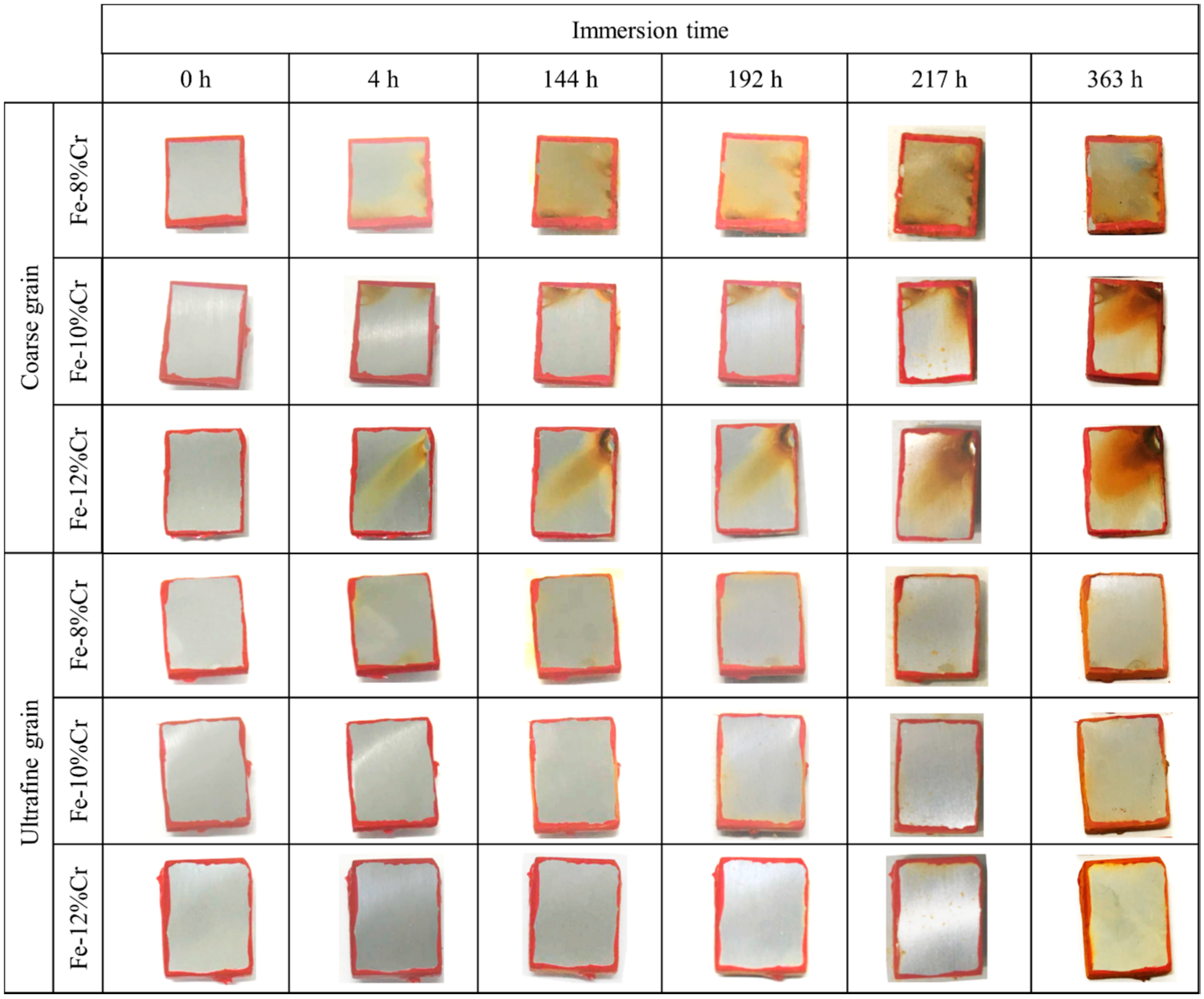
  • In immersion test in 0.6 mol/L NaCl solution, UFG alloys exhibited higher corrosion resistance than CG alloys regardless of Cr contents. Importantly, UFG Fe-8 and 10% Cr alloys with subcritical Cr contents exhibited higher corrosion resistance than CG Fe-12% Cr alloys.
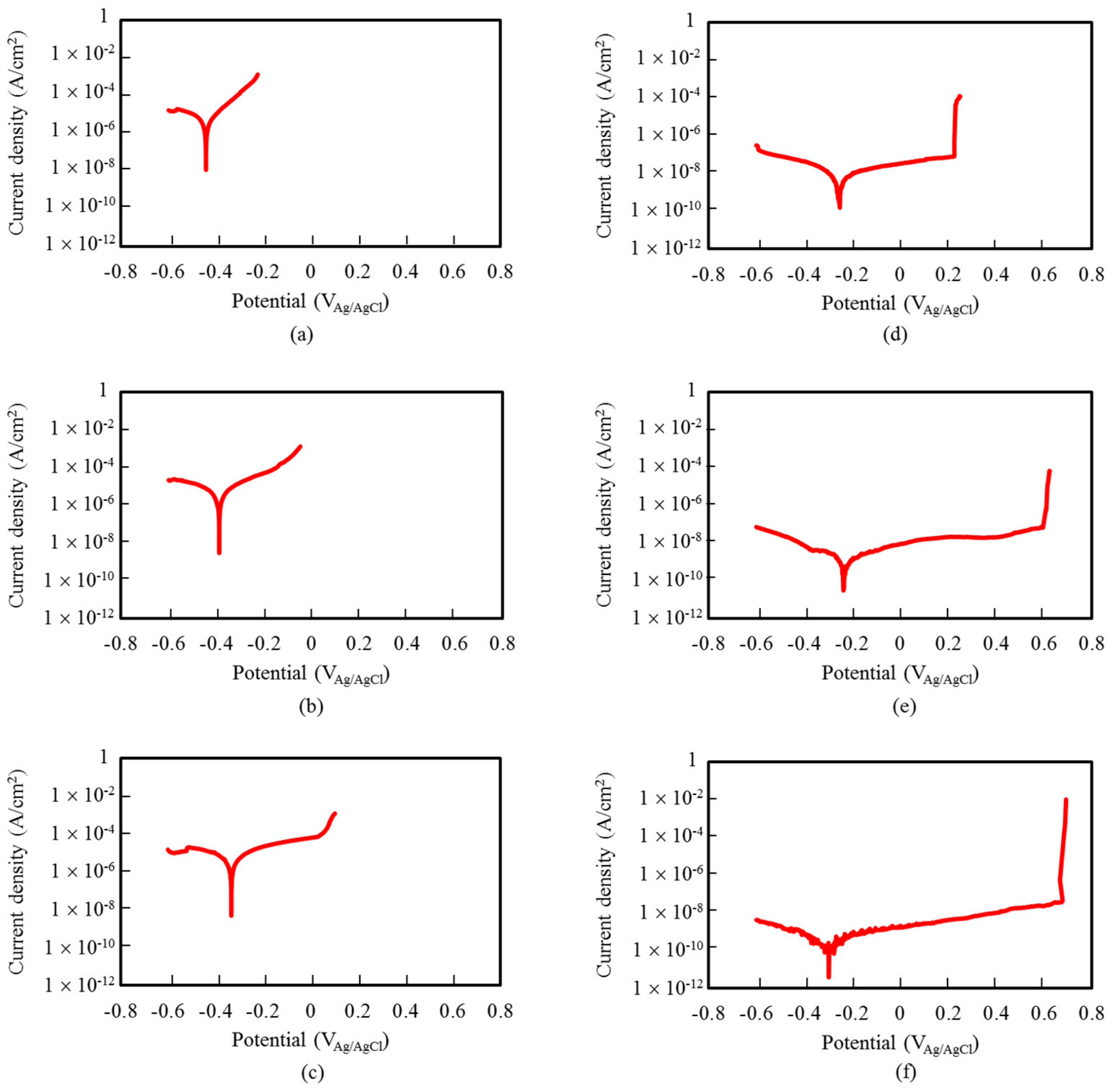
  • UFG alloys including 8% and 10% Cr exhibited passivity in anodic polarization tests whereas CG alloys with the same Cr exhibited polarization curve of the active type. Higher corrosion resistance of UFG alloys can be attributed to the formation of the more protective passive film.
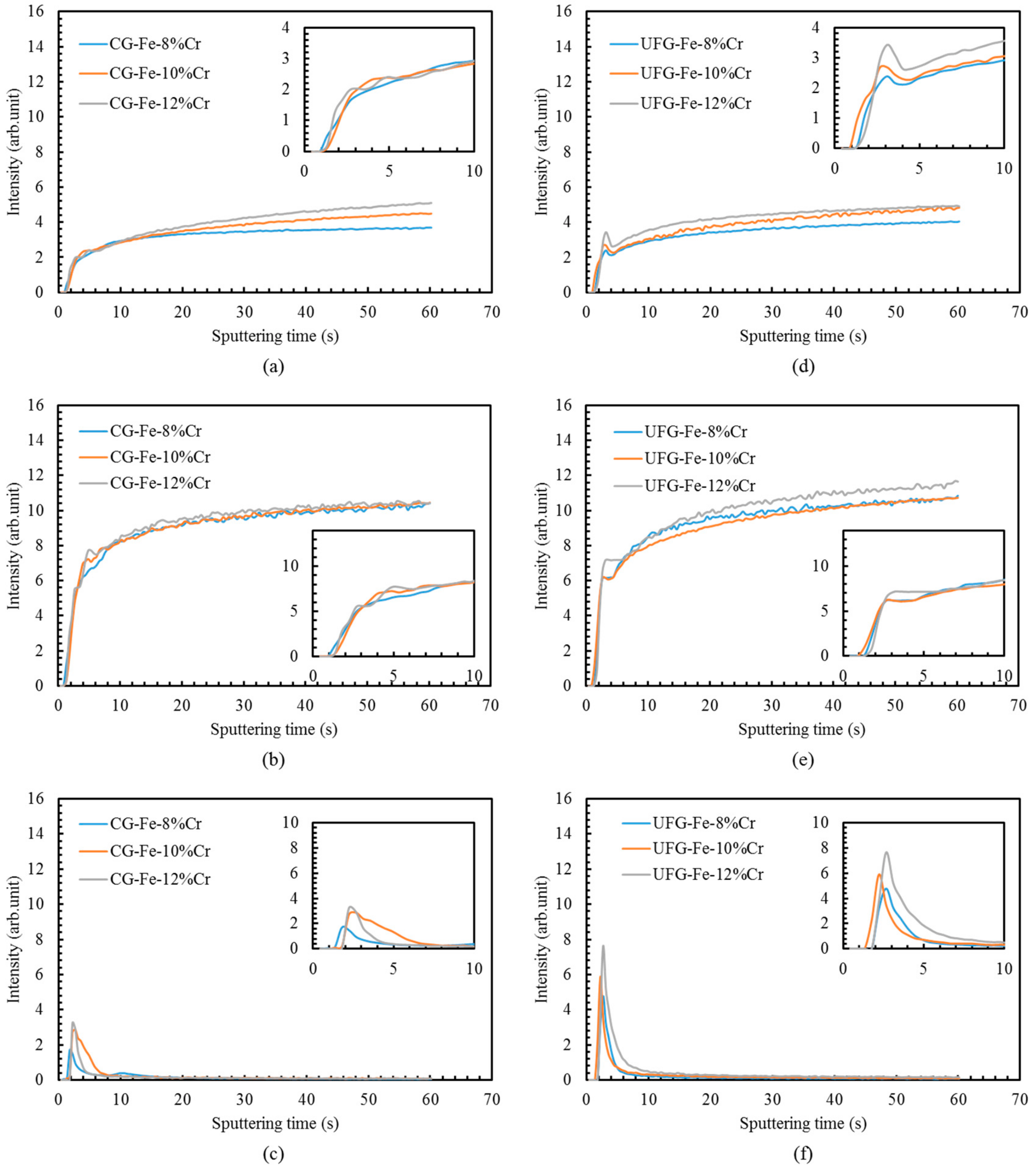
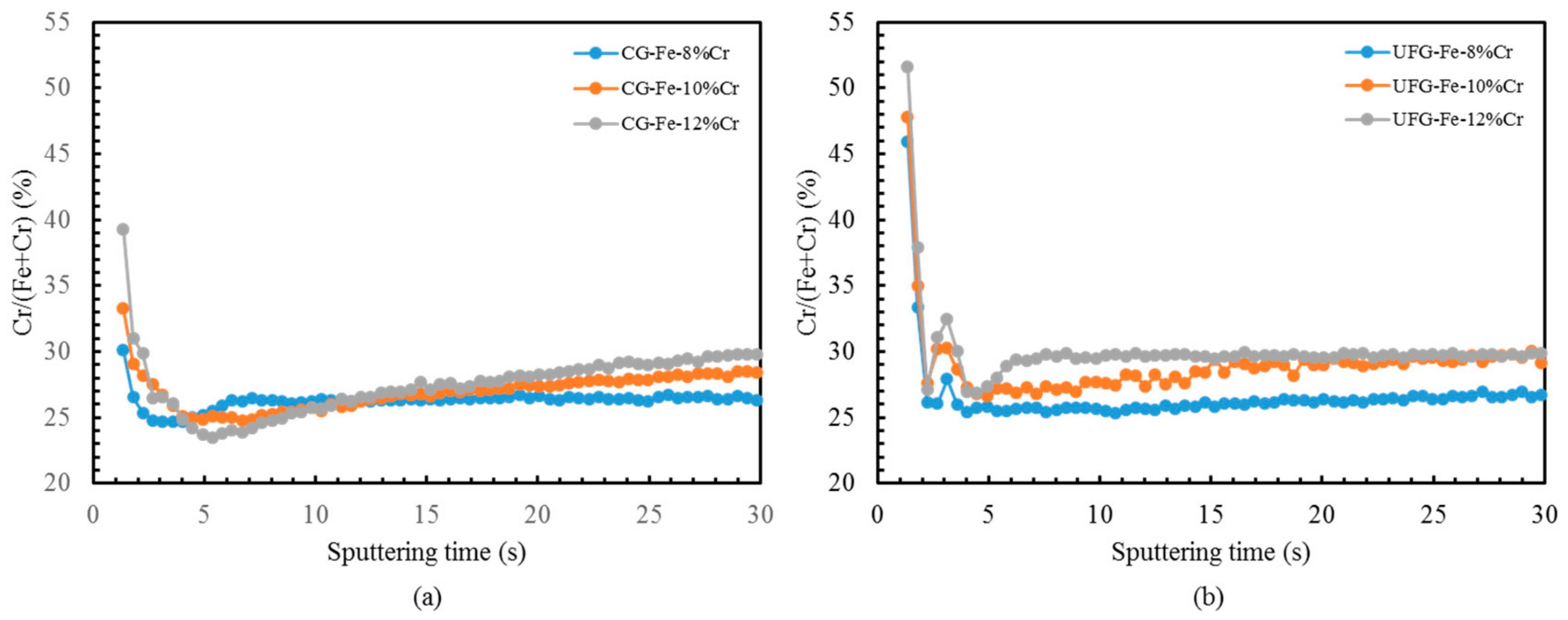
  • Greater Cr enrichment in the passive films was manifested in UFG alloys than CG alloys by GD-OES. The UFG structure appears to promote very rapid diffusion of chromium, thus assisting the formation of the protective passive films that in turn leads to enhanced corrosion resistance.

Author Contributions

All co-authors have contributed substantially to the paper. Muhammad Rifai and Hiroyuki Miyamoto devised the experiments and wrote the paper, Muhammad Rifai performed the experiments and processed the material by ECAP and discussed the result with Hiroyuki Miyamoto and Motohiro Yuasa.

Conflicts of Interest

The authors declare no conflict of interest.

References

  1. Ralston, K.D.; Birbilis, N. Effect of grain size on corrosion: A review. Corrosion 2010, 66, 075005. [Google Scholar] [CrossRef]
  2. Miyamoto, H. Corrosion of ultrafine grained materials by severe plastic deformation, an overview. Mater. Trans. 2016, 57, 559–572. [Google Scholar] [CrossRef]
  3. Raman, R.K.S.; Gupta, R.K. Oxidation resistance of nanocrystalline vis-à-vis microcrystalline Fe-Cr alloys. Corros. Sci. 2009, 51, 316–321. [Google Scholar] [CrossRef]
  4. Raman, R.K.S.; Gupta, R.K.; Koch, C.C. Resistance of nanocrystalline vis-à-vis microcrytalline Fe-Cr alloys to environmental degradation and challenge to their synthesis. Philos. Mag. 2010, 90, 3233–3260. [Google Scholar] [CrossRef]
  5. Gupta, R.K.; Birbilis, N. The influence of nanocrystalline structure and processing route on corrosion of stainless steel: A review. Corros. Sci. 2015, 92, 1–15. [Google Scholar] [CrossRef]
  6. Chen, G.; Gao, Y.; Wu, S.; Hu, J. Corrosion behavior of AISI304 austentic stainless steel fabricated by equal-channel angular pressing. Adv. Mater. Res. 2011, 194–196, 411–415. [Google Scholar] [CrossRef]
  7. Zheng, Z.J.; Gao, Y.; Gui, Y.; Zhu, M. Corrosion behaviour of nanocrystalline 304 stainless steel prepared by equal channel angular pressing. Corros. Sci. 2012, 54, 60–67. [Google Scholar] [CrossRef]
  8. Rifai, M.; Miyamoto, H.; Fujiwara, H. Effects of Strain Energy and Grain Size on Corrosion Resistance of Ultrafine Grained Fe-20%Cr Steels with Extremely low C and N Fabricated by ECAP. Int. J. Corros. 2015, 2015, 386865. [Google Scholar] [CrossRef]
  9. Gupta, R.K.; Singh Raman, R.K.; Koch, C.C. Fabrication and oxidation resistance of nanocrystalline Fe10Cr alloy. J. Mater. Sci. 2010, 45, 4884–4888. [Google Scholar] [CrossRef]
  10. Gupta, R.; Singh Raman, R.K.; Koch, C.C. Electrochemical characteristics of nano and microcrystalline Fe–Cr alloys. J. Mater. Sci. 2012, 47, 6118–6124. [Google Scholar] [CrossRef]
  11. Gupta, R.K.; Singh Raman, R.K.; Koch, C.C.; Murty, B.S. Effect of nanocrystalline structure on the corrosion of a Fe20Cr alloy. Int. J. Electrochem. Sci. 2013, 8, 6791–6806. [Google Scholar]
  12. Pisarek, M.; Kedzierzawski, P.; Janik-Czachor, M.; Kurzydlowski, K.J. Effect of hydrostatic extrusion on the corrosion resistance of type316 stainless steel. Corrosion 2008, 64, 131–137. [Google Scholar] [CrossRef]
  13. Pisarek, M.; Kȩdzierzawski, P.; Janik-Czachor, M.; Kurzydłowski, K.J. Effect of hydrostatic extrusion on passivity breakdown on 303 austenitic stainless steel in chloride solution. J. Solid State Electrochem. 2009, 13, 283–291. [Google Scholar] [CrossRef]
  14. Krawczynska, A.T.; Gloc, M.; Lublinska, K. Intergranular corrosion resistance of nanostructured austenitic stainless steel. J. Mater. Sci. 2013, 48, 4517–4523. [Google Scholar] [CrossRef]
  15. Balusamy, T.; Kumar, S.; Sankara Narayanan, T.S.N. Effect of surface nanocrystallization on the corrosion behaviour of AISI 409 stainless steel. Corros. Sci. 2010, 52, 3826–3834. [Google Scholar] [CrossRef]
  16. Mordyuk, B.N.; Prokopenko, G.I.; Vasylyev, M.A.; Iefimov, M.O. Effect of structure evolution induced by ultrasonic peening on the corrosion behavior of AISI-321 stainless steel. Mater. Sci. Eng. A 2007, 458, 253–261. [Google Scholar] [CrossRef]
  17. Meng, G.; Li, Y.; Wang, F. The corrosion behavior of Fe–10Cr nanocrystalline coating. Electrochim. Acta 2006, 51, 4277–4284. [Google Scholar] [CrossRef]
  18. Pan, C.; Liu, L.; Bin, Z.; Wang, F. The electrochemical corrosion behaivor of nanocrystalline 304 stainless steel prepared by magnetron sputtering. J. Electrochem. Soc. 2012, 159, C453–C460. [Google Scholar] [CrossRef]
  19. Olefjord, I.; Brox, B.; Jelvestam, U. Surface Composition of Stainless Steels during Anodic Dissolution and Passivation Studied by ESCA. J. Electrochem. Soc. 1985, 132, 2854–2861. [Google Scholar] [CrossRef]
  20. Jones, D.A. Principles and Prevention of Corrosion, 2nd ed.; Prentice-Hall: Upper Saddle River, NJ, USA, 1996; ISBN 10-0029464390. [Google Scholar]
  21. Schneider, M.; Zieiger, W.; Scharnweber, D.; Worch, H. Electrochemical behaivor of nanocrystalline FeAl8 and FeCr10 alloys. Mater. Sci. Forum 1996, 225–227, 819–824. [Google Scholar] [CrossRef]
  22. Streicher, M.A. Austenitic and Ferritic stainless steels. In Uhlig’s Corrosion Handbook; Revie, R.W., Ed.; John Wiley and Sons: Hoboken, NJ, USA, 2011; ISBN 0470080329. [Google Scholar]
  23. Valiev, R.Z.; Gertsman, V.Y.; Kaibyshev, O.A. Non-equillibrium state and recovery of grain boundary structure. Phys. Status Solidi 1983, 78, 177–187. [Google Scholar] [CrossRef]
  24. Sergueeva, A.V.; Stolyarov, V.V.; Valiev, R.Z.; Mukherjee, A.K. Enhanced superplasticity in a Ti-6Al-4V alloy processed by severe plastic deformation. Scr. Mater. 2000, 43, 819–824. [Google Scholar] [CrossRef]
  25. Divinski, S.V.; Reglitz, G.; Rösner, H.; Estrin, Y.; Wilde, G. Ultra-fast diffusion channels in pure Ni severely deformed by equal-channel angular pressing. Acta Mater. 2011, 59, 1974–1985. [Google Scholar] [CrossRef]
  26. Miyamoto, H.; Harada, K.; Mimaki, T.; Vinogradov, A.; Hashimoto, S. Corrosion of ultra-fine grained copper fabricated by equal-channel angular pressing. Corros. Sci. 2008, 50, 1215–1220. [Google Scholar] [CrossRef]
  27. Li, H.; Jiang, Z.H.; Ma, Q.F.; Li, Z. Influence of cold working and grain size on pitting corrosion resistance of ferritic stainless steel. Adv. Mater. Res. 2011, 217–218, 1180–1184. [Google Scholar] [CrossRef]
  28. Rifai, M.; Bagherpour, E.; Yamamoto, G.; Yuasa, M.; Miyamoto, H. Transition of Dislocation Structures in Severe Plastic Deformation and Its Effect on Dissolution in Dislocation Etchant. Adv. Mater. Sci. Eng. 2018, 2018, 4254156. [Google Scholar] [CrossRef]
  29. Fischmeister, H.; Roll, U. Passive layers on stainless steels: A survey of surface analysis: A survey of surface analysis results. Z. Anal. Chem. 1984, 319, 639–645. [Google Scholar] [CrossRef]
  30. Kirchheim, R.; Heine, B.; Fischmeister, H.; Hofmann, S.; Knote, H.; Stolz, U. The passivity of iron-chromium alloys. Corros. Sci. 1989, 29, 899–917. [Google Scholar] [CrossRef]
  31. Hamm, D.; Ogle, K.; Olsson, C.O.A.; Weber, S.; Landolt, D. Passivation of Fe-Cr alloys studied with ICP-AES and EQCM. Corros. Sci. 2002, 44, 1443–1456. [Google Scholar] [CrossRef]
  32. Olsson, C.O.A.; Landolt, D. Passive films on stainless steels—Chemistry, structure and growth. Electrochim. Acta 2003, 48, 1093–1104. [Google Scholar] [CrossRef]
  33. Sieradzki, K.; Newman, R.C. A percolation model for passivation in stainless steels. J. Electrochem. Soc. 1986, 133, 1979–1980. [Google Scholar] [CrossRef]
  34. Newman, R.C.; Foong, T.M.; Sieradzki, K. Validation of a percolation model for passivation of Fe-Cr alloys: Current efficiency in the incompletely passivated state. Corros. Sci. 1988, 28, 523–527. [Google Scholar] [CrossRef]
  35. Qian, S.; Newman, R.C.; Cottis, R.A. Validation of a percolation model for passivation of Fe-Cr alloys: Two-dimensional computer simulation. J. Electrochem. Soc. 1990, 137, 435–439. [Google Scholar] [CrossRef]
  36. Williams, D.E.; Newman, R.C.; Song, Q.; Kelly, R.G. Passivity breakdown and pitting corrosion of binary alloys. Nature 1991, 350, 216–219. [Google Scholar] [CrossRef]
  37. Hamada, E.; Yamada, K.; Nagoshi, M.; Makiishi, N.; Sato, K.; Ishii, T.; Fukuda, K.; Ishikawa, S.; Ujiro, T. Direct imaging of native passive film on stainless steel by aberration corrected STEM. Corros. Sci. 2010, 52, 3851–3854. [Google Scholar] [CrossRef]
  38. Wang, Z.B.; Tao, N.R.; Tong, W.P.; Lu, J.; Lu, K. Diffusion of chromium in nanocrystalline iron produced by means of surface mechanical attrition treatment. Acta Mater. 2003, 51, 4319–4329. [Google Scholar] [CrossRef]
  39. Chao, C.Y.; Lin, L.F.; Macdonald, D.D. A point defect model for anodic passive films 2. Chemical breakdown and pit initiation. J. Electrochem. Soc. 1981, 128, 1194–1198. [Google Scholar] [CrossRef]
  40. Chao, C.Y.; Lin, L.F.; Macdonald, D.D. A point defect model for anodic passive films 1. Film growth kinetics. J. Electrochem. Soc. 1981, 128, 1187–1194. [Google Scholar] [CrossRef]
  41. Macdonald, D.D. The point defect model for the passive state. J. Electrochem. Soc. 1992, 139, 3434–3449. [Google Scholar] [CrossRef]
Figure 1. Electron backscatter diffraction (EBSD) images acquired from coarse-grained (CG) alloys with (a) 8%, (b) 10% and (c) 12% Cr and ultrafine grained (UFG) alloys prepared by equal-channel angular pressing (ECAP) with (d) 8%, (e) 10% and (f) 12% Cr.
Metals 08 00149 g001
Figure 2. Photographic images showing test specimens after immersion in a 0.6 mol/L NaCl solution for 4, 144, 192, 217 and 363 h.
Metals 08 00149 g002
Figure 3. Anodic polarization plots for CG alloys with (a) 8%, (b) 10% and (c) 12% Cr and UFG alloys prepared by ECAP with (d) 8%, (e) 10% and (f) 12% Cr.
Metals 08 00149 g003
Figure 4. Laser microscopy images showing pitting of test specimens for CG alloys with (a) 8%, (b) 10% and (c) 12% Cr and UFG alloys prepared by ECAP with (d) 8%, (e) 10% and (f) 12% Cr.
Metals 08 00149 g004
Figure 5. Glow discharge optical emission spectrometry (GD OES) profiles of CG alloys (a) Cr, (b) Fe and (c) O, and UFG alloys prepared by ECAP (d) Cr, (e) Fe and (f) O.
Metals 08 00149 g005
Figure 6. Cr/(Fe + Cr) ratio as determined by GD-OES as a function of sputtering time for (a) CG and (b) UFG alloys prepared by ECAP.
Metals 08 00149 g006

