Characterization on the Microstructure Evolution and Toughness of TIG Weld Metal of 25Cr2Ni2MoV Steel after Post Weld Heat Treatment


1
Department of Mechanical Engineering, Tsinghua University, Beijing 100084, China
2
Shanghai Electric Power Generation Equipment Co., Ltd., Shanghai 200240, China
3
Shanghai Key Laboratory of Materials Laser Processing and Modification, School of Materials Science and Engineering, Shanghai Jiao Tong University, Shanghai 200240, China
*
Authors to whom correspondence should be addressed.
Metals 2018, 8(3), 160; https://doi.org/10.3390/met8030160
Submission received: 16 January 2018
/
Revised: 26 February 2018
/
Accepted: 3 March 2018
/
Published: 6 March 2018
(This article belongs to the Special Issue Microstructure and Mechanical Properties of Structural Metals and Alloys)
Abstract
:The microstructure and toughness of tungsten inert gas (TIG) backing weld parts in low-pressure steam turbine welded rotors contribute significantly to the total toughness of the weld metal. In this study, the microstructure evolution and toughness of TIG weld metal of 25Cr2Ni2MoV steel low-pressure steam turbine welded rotor under different post-weld heat treatment (PWHT) conditions are investigated. The fractography and microstructure of weld metal after PWHT are characterized by optical microscope, SEM, and TEM, respectively. The Charpy impact test is carried out to evaluate the toughness of the weld. The optical microscope and SEM results indicate that the as-welded sample is composed of granular bainite, acicular ferrite and blocky martensite/austenite (M-A) constituent. After PWHT at 580 °C, the blocky M-A decomposes into ferrite and carbides. Both the number and size of precipitated carbides increase with holding time. The impact test results show that the toughness decreases dramatically after PWHT and further decreases with holding time at 580 °C. The precipitated carbides are identified as M23C6 carbides by TEM, which leads to the dramatic decrease in the toughness of TIG weld metal of 25Cr2Ni2MoV steel.
1. Introduction
Steam turbines play an important role in modern power plants. As a result of concerns related to the environmental impact from pollutants and greenhouse gas, the power industry has had to improve thermal efficiency by developing ultra-supercritical (USC) combustion technology, which has led to elevated steam temperatures and continuously increasing demand being placed on their components’ performance [1]. The harsher working conditions exert extra stress on all moving parts, demanding higher reliability with much-enhanced mechanical properties for all components [2,3]. Steam turbine rotors are one of the most critical and highly stressed parts in steam turbines, experiencing centrifugal force, torsional force and bending stress. Thus, the material used to manufacture steam turbine rotors needs to have excellent performance, such as high ductility, deep hardenability, high strength, high fatigue strength and creep resistance [4,5,6]. NiCrMoV refractory steel has been proved to be a suitable material for meeting these requirements of steam turbine rotor materials [7,8,9]. However, it is difficult to manufacture high-quality steam turbine rotors by forging directly, because of their heavy section and large dimensions. Thus, welded rotors have been widely used, with advantages including lighter weight, higher rigidity, easier manufacturing process, shorter production cycle, lower cost, and excellent performance [10,11].
In practice, for large-scale rotors, multi-layer and multi-pass welding technologies are utilized due to their advantages in terms of normalizing the pre-layer or pre-pass microstructure, thus increasing the ductility and improving the welding quality. The narrow gap-welding method is frequently chosen in the manufacturing of large-scale rotors, in order to join several forged parts with less filler wire consumption and weld deformation. Despite the weld quality of narrow-gap tungsten inert-gas welding (NG-TIG) is better than that of narrow-gap submerged-arc welding (NG-SAW), NG-SAW is generally employed to manufacture heavy section rotors, due to its higher efficiency and lower cost [12,13,14,15]. In the manufacturing process of large-scale rotors, NG-TIG is firstly employed for backing weld, and then multi-layer and multi-pass NG-SAW is used to manufacture the welded rotor.
After the welding process, post-weld heat treatment (PWHT) for the welded joints is invariably carried out, and is indispensable for eliminating welding stress and improving comprehensive mechanical properties [16,17,18,19,20]. Tempering is one of the methods for PWHT that is able to release the welding stress and stabilize the microstructure of the welded rotor steel [21,22,23,24]. Generally, the welded rotor is heated to a higher temperature with a certain heating speed and then the welded rotor is insulated for a period of time followed by a cooling process with a lower cooling rate in the furnace or air because of the large size and high thickness of the welded rotor [25,26].
For a qualified weld metal, the creep property and fatigue resistance are essential performances, while good impact toughness at room temperature should be also taken into account to ensure reliability during the testing and startup or shut-down of plants. However, the weld metal of NiCrMoV refractory steel is susceptible to tempered embrittlement as a consequence of tempering within a specified temperature range, leading to a dramatic decrease in impact toughness [27]. Salemi et al. [8] investigated the effect of tempering temperature on the mechanical properties and fracture morphology of NiCrMoV steel. They found that the impact energy was improved by increasing the tempering temperature without any evidence of tempered martensite embrittlement. Wang et al. [28] studied the microstructure and impact toughness of 15Cr2Ni3MoW steel after tempering at different temperatures. The results showed that a large amount of stabilized martensite/austenite (M-A) islands appeared after the tempering treatment at 350 °C, while the M-A islands decomposed into precipitated carbide distributing along the grain boundary, which is responsible for the tempering brittleness. As the multi-layer and multi-pass NG-SAW part constitutes the majority of weld metal, most research has placed an emphasis on the microstructure and mechanical properties of NG-SAW parts. Li et al. [29,30] investigated toughness weak point of bainite weld metal of NiCrMoV refractory steel. They found that the carbon-rich areas containing much more M-A blocks in the incomplete phase change zone of layers between two adjacent beads were responsible for the decrease of toughness. Furthermore, the influence of the M-A blocks on the weld toughness was closely related to the distribution, pattern and dimension. Zhang et al. [31] concluded that the precipitation and aggregation of carbides was disadvantageous to the toughness. However, little study has been focused on the microstructure and toughness of TIG backing weld parts, which is an indispensable part and contributes to the toughness of whole weld metal significantly. In this study, the toughness of the TIG weld metal of 25Cr2Ni2MoV steel is evaluated by Charpy impact test. The fractography and microstructure evolution under different PWHT conditions are characterized by optical microscope (OM), scanning electron microscopy (SEM) and transmission electron microscopy (TEM) to reveal the fracture mechanism.
2. Materials and Methods
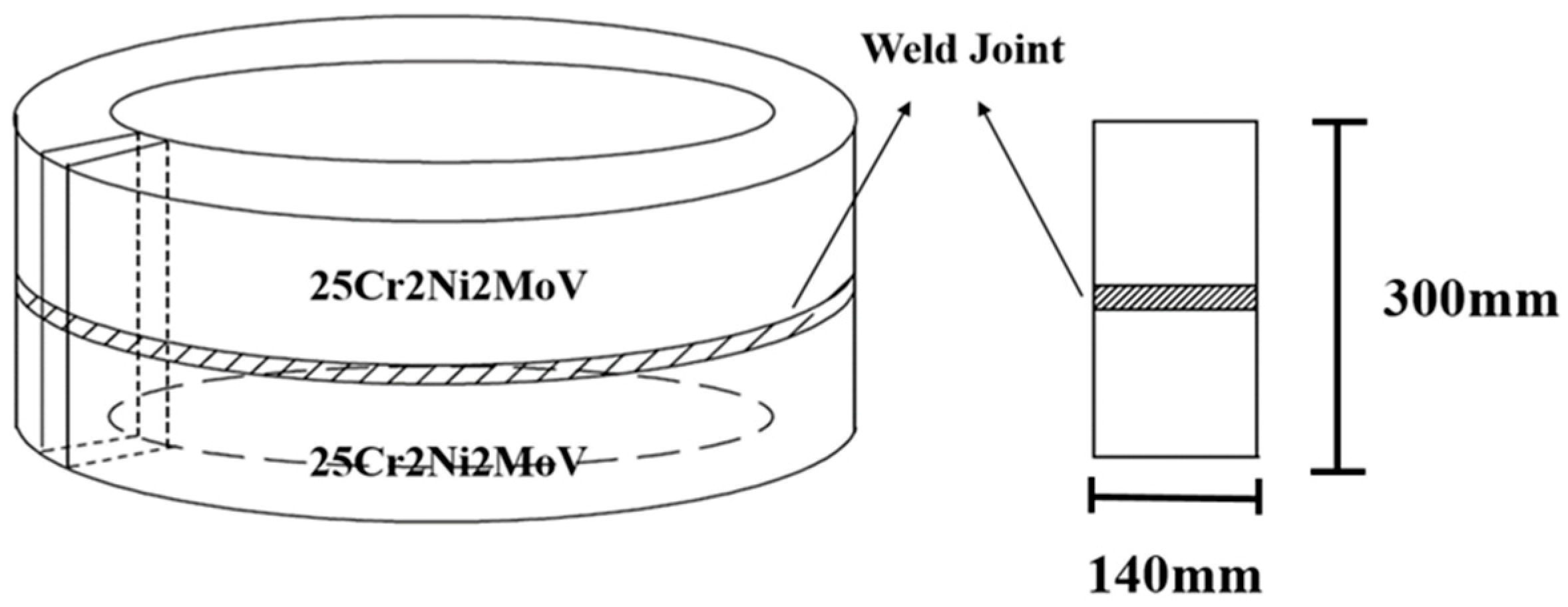
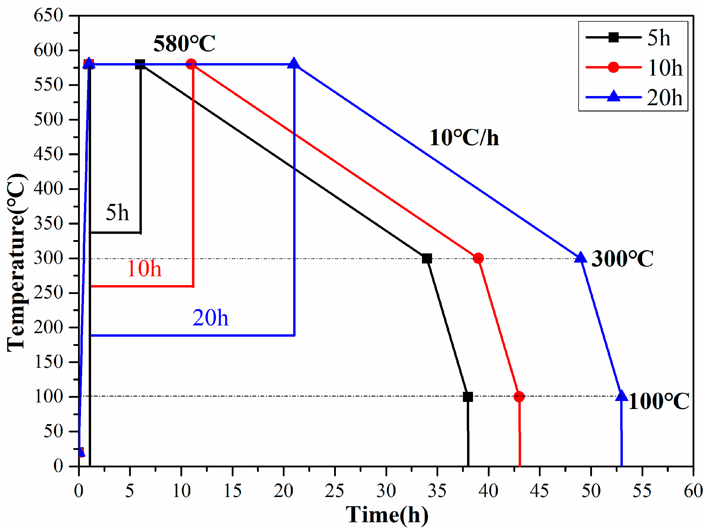
The base metal used in this study is 25Cr2Ni2MoV steel and the filler metal is 2.5% Ni low-alloy steel. The chemical compositions of the base metal (BM) and the filler metals (FM) are listed in Table 1. The 25Cr2Ni2MoV steel is welded by TIG and the welding parameters are listed in Table 2. The dimensions and position of samples used in this study are shown in Figure 1. All the samples were carefully taken from the middle of the weld joint. After the welding process, the samples were immediately subjected to PWHT in the furnace with different heat treatment parameters, including hold times of 5 h, 10 h and 20 h at temperature of 580 °C. The detailed PWHT process is shown in Figure 2.
The Charpy impact test was conducted at room temperature to evaluate the impact toughness of the weld metal treated by different PWHT process according to the ASTM E23-2008 standard procedure. Standard Charpy V-notch (CVN) samples with dimension: length × width × thickness = 55 mm × 10 mm × 10 mm, were cut from the weld metal and Charpy impact tests were performed by pendulum impact tester of PTM2200-D1 impact testing system (SUNS Technology Stock Co. Ltd., Shenzhen, China). To ensure the reliability of the results, each kind of sample was tested five times. After impact tests, the fractography for the impact fractures of different samples were observed by scanning electron microscope (SEM).
In order to analyze the microstructure evolution and mechanism of impact fracture of weld metal with different PWHT, OM, SEM and TEM were conducted to observe the microstructure. The weld metal samples without PWHT, as well as those treated by different PWHTs, were mounted and mechanically polished according to standard metallographic procedures for microstructure observation. The samples were etched by 4% Nitric acid and alcohol solution, then the microstructure of these specimens was analyzed by OM and SEM. The fine microstructure of weld metal was further investigated by transmission electron microscope (TEM) on FEI Tecnai G2 F20 FEG-TEM (FEI, Hillsboro, OR, USA) equipped with an energy-dispersive X-ray spectrometer (EDS) at 200 kV. The TEM samples were prepared by mechanical grinding and polishing followed by thinning to an electron-transparent thickness by low-energy Ar ion milling and subsequent ion polishing using Gatan PIPS, model 691 (Gatan, Inc., Pleasanton, CA, USA).
3. Results and Discussion
3.1. Microstructure Analysis
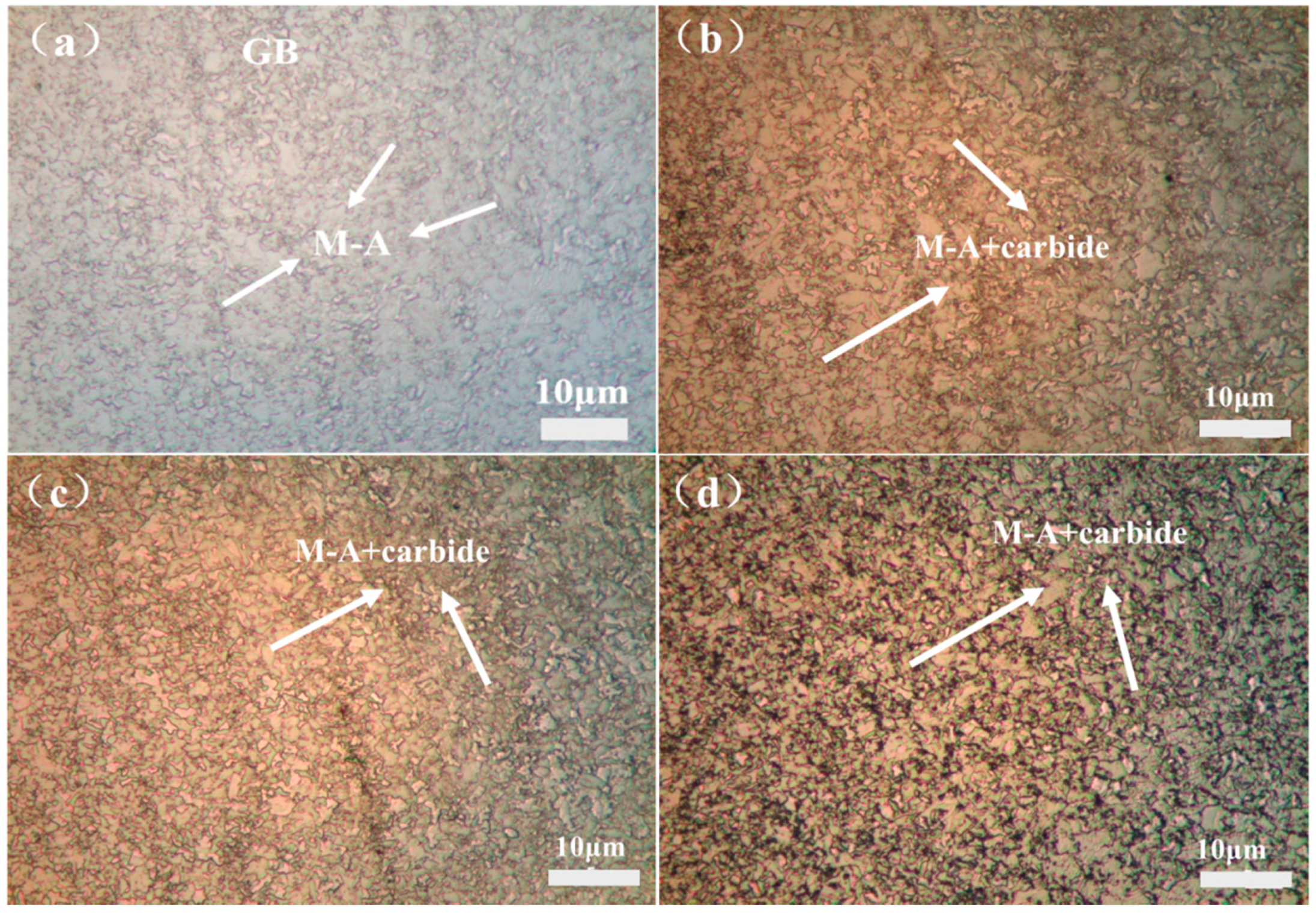
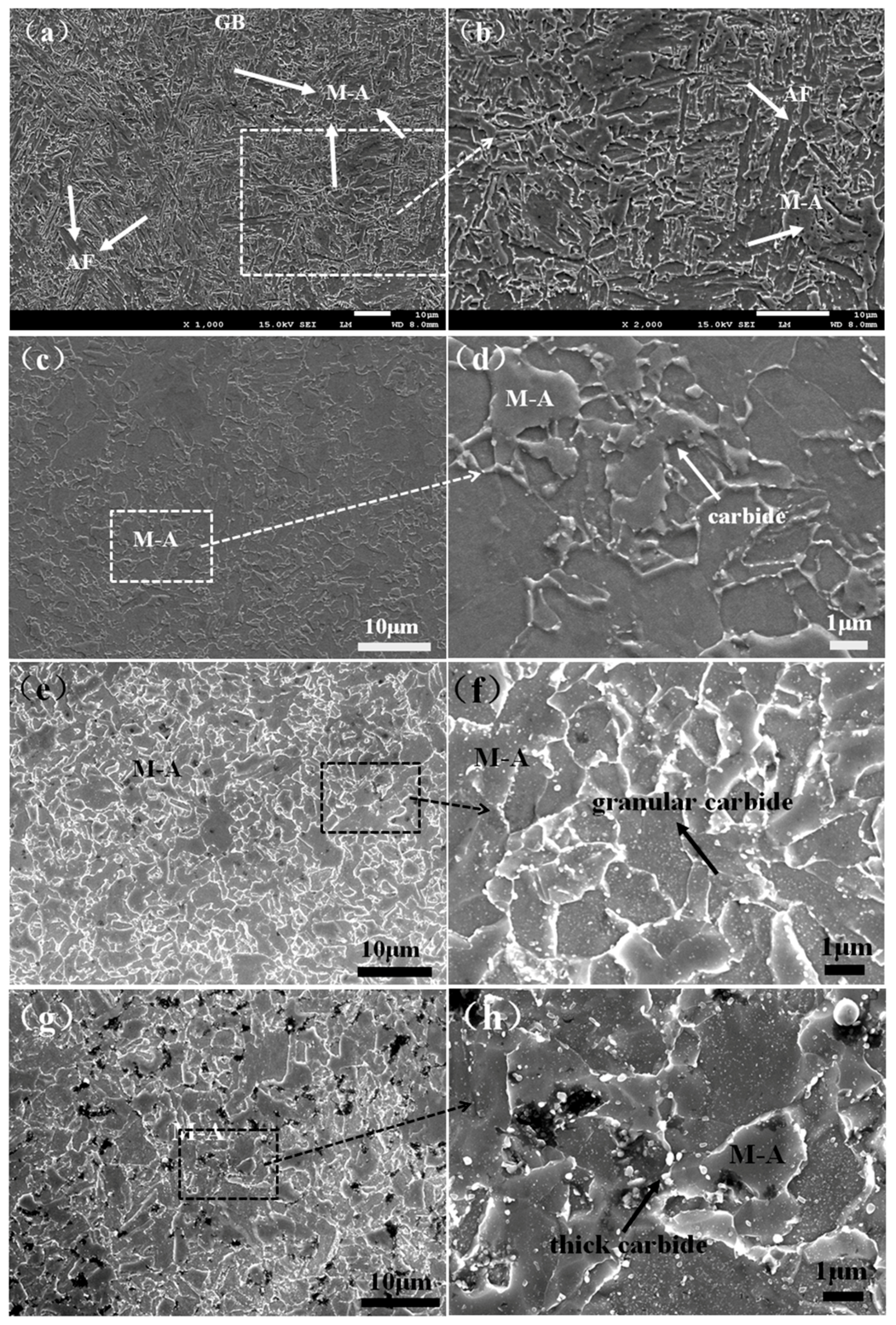
Figure 3 shows the representative metallographic images of the as-welded sample and the samples with PWHT with different hold times. SEM was also carried out to further observe the microstructure of the weld metal, and the results are shown in Figure 4. Figure 3a and Figure 4a,b show the microstructure of the as-welded sample. The microstructure of as-welded sample is mainly composed of granular bainite, (GB) and a certain amount of acicular ferrite (AF). In addition, a large number of blocky M-A (martensite/austenite) are homogeneously distributed in the bainite and ferrite matrix. With further observation, it can be seen that blocky M-A with size of less than 10 μm is not decomposed, and no carbide precipitation is observed. Whereas, after PWHT, the blocky M-A decomposes into ferrite and carbide, and the decomposition continues with the increase of the holding time. In addition, the size of blocky M-A also increases with the increase of holding time. As shown in Figure 3b and Figure 4c,d, after PWHT with a holding time of 5 h, the blocky M-A decomposes slightly. After PWHT with holding time of 10 h, the blocky M-A blocks decompose with small granular carbides distributing around the blocky M-A, as can be seen from Figure 3c and Figure 4e,f. For PWHT with holding time of 20 h, the blocky M-A dramatically decomposes and a large amount of thick carbides precipitate around the boundary. Furthermore, some of the carbides have become spheroidizing.
3.2. Charpy Impact Results
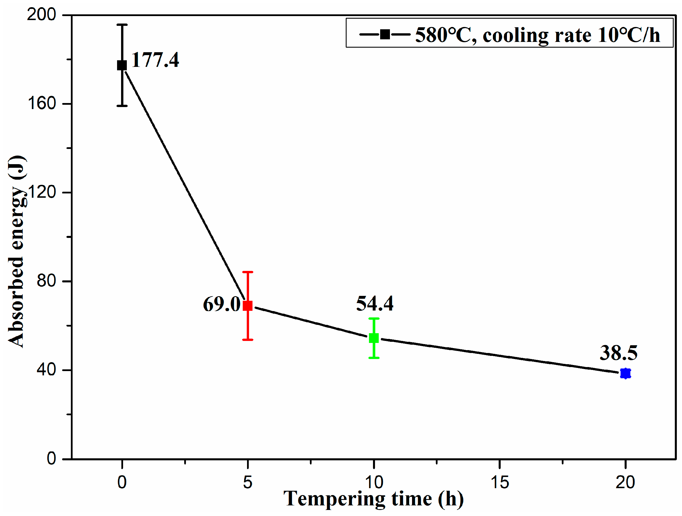
The Charpy impact test was carried out at room temperature to evaluate the toughness of the weld metal with different hold times at 580 °C in PWHT. The absorbed energies in the Charpy impact test versus hold times, as well as the deviation from the average value, are shown in Figure 5. It can be seen that the as-welded metal had the highest absorbed energy, at around 177.4 J. The absorbed energies of the weld metal dramatically decrease after PWHT and that gradually decreases with the hold time from 5 h to 20 h. It can be expected that the absorbed energies of the weld metal will continue to decrease with increasing of the hold time in PWHT to a certain extent. Specifically, the absorbed energy of weld metal with a holding time of 5 h is 69.0 J. When the hold time is 10 h, the absorbed energy is about 54.4 J. The weld metal with holding time of 20 h has the lowest absorbed energy of 38.5 J, which is more than four times lower than the as-welded one. The dramatic decrease of the toughness of the weld metal can be attributed to the microstructure evolution caused by the different PWHT processing. Associating the microstructure evolution of weld metal after PWHT with the Charpy impact test results, it is concluded that the precipitation of carbides along the boundaries of the blocky M-A has a great influence on the toughness of the sample.
3.3. Fractography Characterization
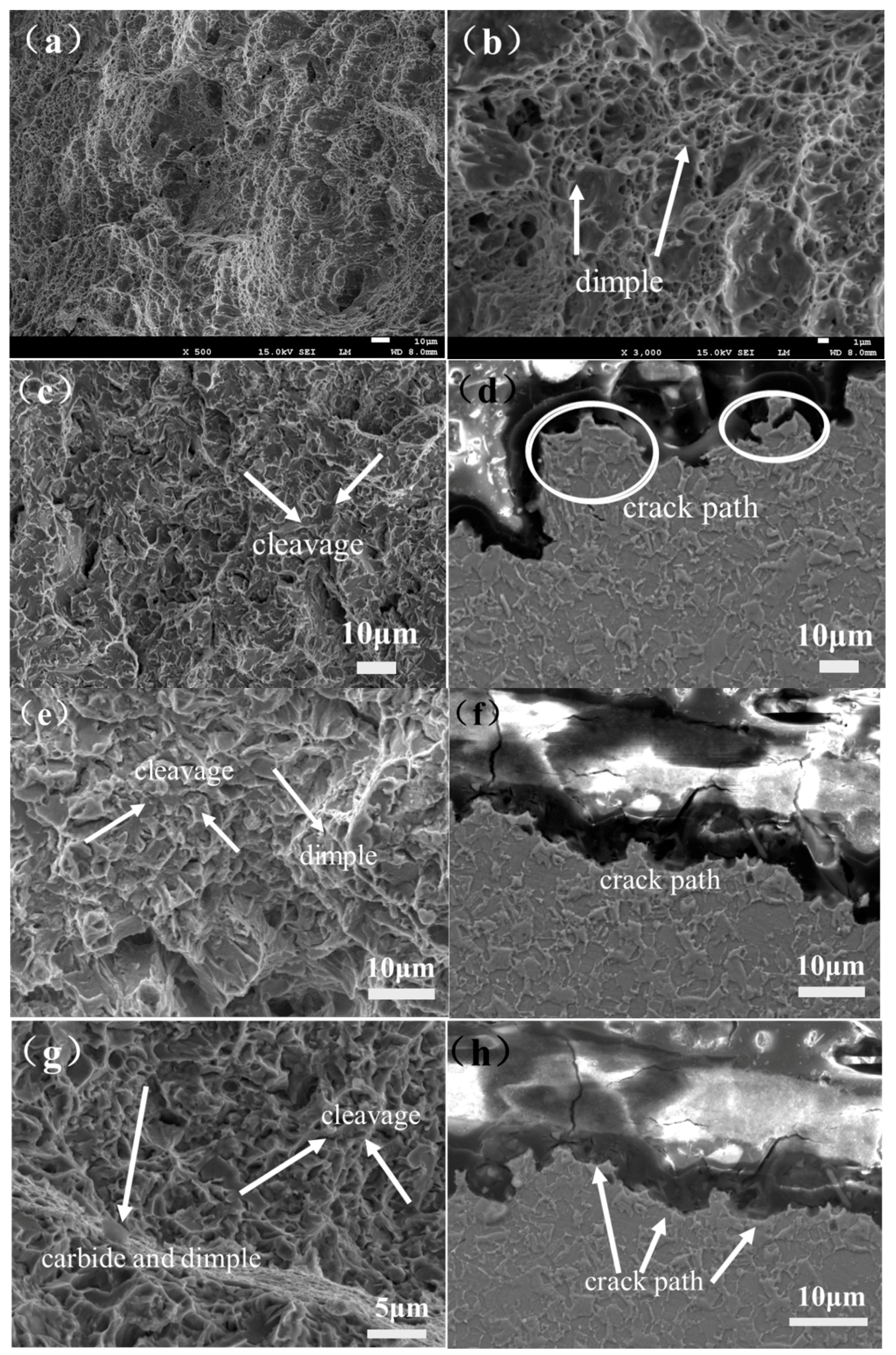
The morphology and cross-section of the fracture surface of the samples with different holding times were characterized by SEM to investigate the mechanism of fracture. Figure 6a,b presents the SEM fractograph of the as-welded sample. The presence of dimples is obvious at the fracture surface of this sample, indicating a ductile fracture mechanism. However, in general, the fracture mechanism transforms from ductile fracture to the combined mechanism, with both brittle fracture and ductile fracture after PWHT. Specifically, the fractography of weld metal after 5 h holding time shows characteristics of quasi cleavage fracture with numbers of cleavage facets as shown in Figure 6c. Figure 6d shows the unbroken blocky M-A blocks located along the fracture surface, and the size of cleavage fracture surface is also in agreement with that of the blocky M-A blocks, indicating that the boundary of blocky M-A blocks provides a crack propagation path when the sample is impacted. When the holding time is 10 h, the fracture morphology of the sample shows the characteristics of quasi cleavage fracture containing a large number of cleavage facets. However, compared to the sample with 5 h holding time, there are a number of dimples around the cleavage facets, which reveals that the initiation of cleavage facets is possibly the micro crack around the dimples. As shown in Figure 6f, the crack propagation path is still along the boundary of blocky M-A blocks, which is similar to the mechanism of sample with 5 h holding time. When the holding time increases to 20 h, the fracture morphology of the sample is still that of a quasi cleavage fracture with lots of cleavage facets. More dimples can easily be found on the fracture surface when compared to the sample with 10 h holding time. However, carbide particles can be clearly seen in the dimples, as shown in Figure 6g. From this result, it can be inferred that the initiation of micro cracks, which grow into cleavage facets, is attributed to carbide particles precipitated around the blocky M-A. The cross-section of the fracture surface (Figure 6h) shows that the crack propagation path is also along the boundary of blocky M-A. In association with the OM and SEM microstructure characterization, it can be concluded that the carbide particle precipitated around the boundary of blocky M-A grows larger and the number becomes more with the increase of the holding time. Consequently, there is more potential initiation of micro cracks in the weld metal, which is responsible for the decrease of toughness after PWHT.
3.4. TEM Characterization
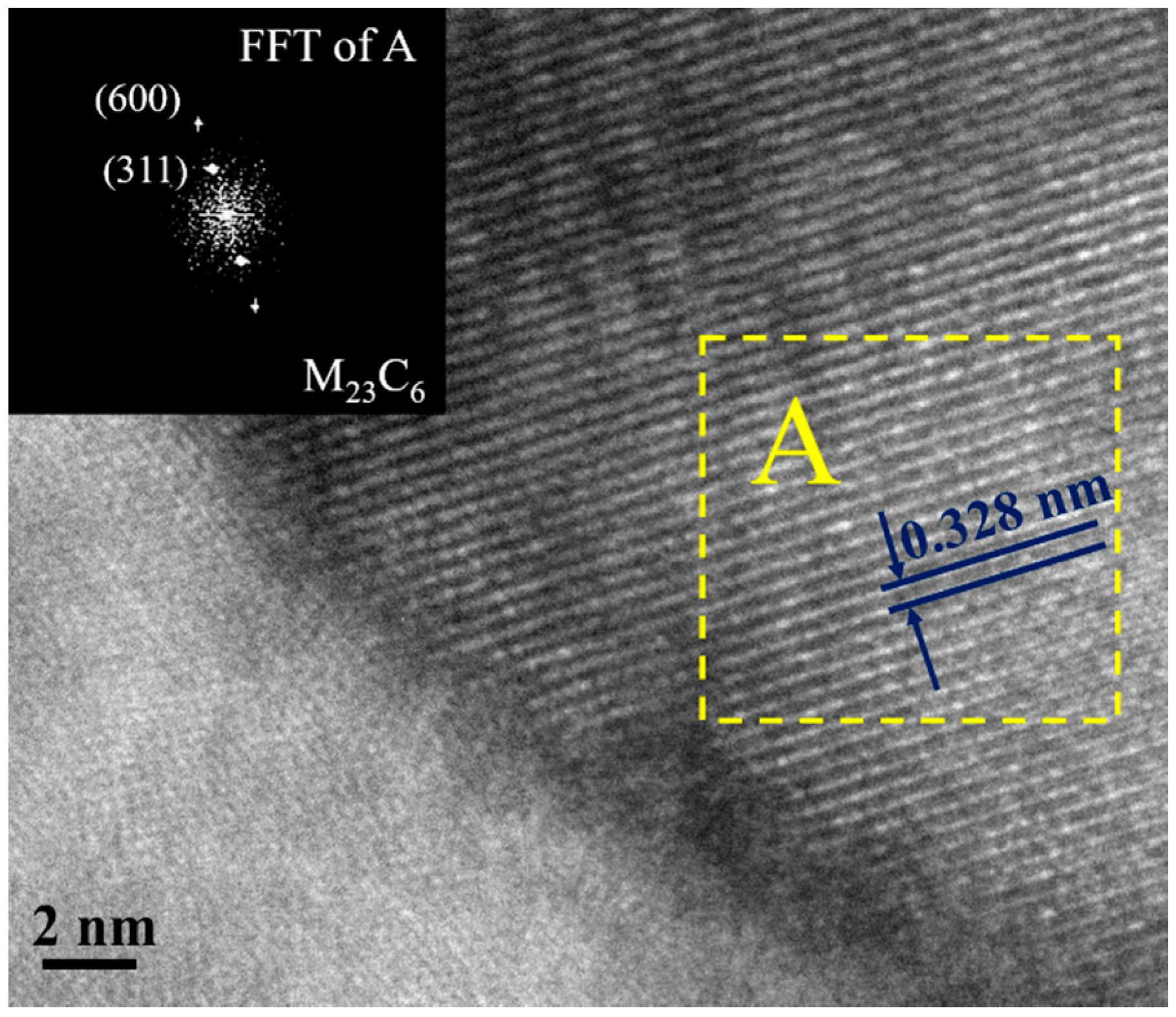
In order to further investigate the fine microstructure and the precipitated carbides around blocky M-A, TEM was conducted, and the results are presented as Figure 7, Figure 8 and Figure 9. As shown in Figure 7, there is no carbide precipitated from the blocky M-A blocks in the as-welded sample. The selected area electron diffraction (SAED) pattern as shown in Figure 7b reveals that the substrate is mainly composed of ferrite. Figure 8 displays the typical TEM images of the samples after PWHT with a hold time of 20 h. It can be obviously seen that a large amount of needle-like and blocky carbides with dimensions of about 100–200 nm are precipitated from the M-A blocks and ferrite substrate. According to the SAED patterns of precipitated carbides and HR-TEM result (in Figure 9), the precipitated carbides are identified as M23C6 carbides. Associating the OM, SEM and TEM microstructure characterization with the dramatic decrease in toughness of TIG weld metal of 25Cr2Ni2MoV steel, it is concluded that the precipitation of M23C6 carbides leads to the significant decrease in the toughness.
4. Conclusions
The microstructure evolution, toughness and the fracture morphology of the weld metal of 25Cr2Ni2MoV steel treated with different PWHT holding times have been studied. The results obtained can be summarized as follows:
- The microstructure of the as-welded sample is composed of granular bainite and acicular ferrite. In addition, a large number of blocky M-A is homogeneously distributed in the bainite and ferrite matrix. The as-welded sample exhibits the highest toughness of 177.4 J.
- After PWHT at 580 °C, the blocky M-A decomposes into ferrite and carbides, and the carbide particles are distributed along the boundary of the blocky M-A. As the holding time in PWHT is increased, more blocky M-A decomposes, and both the number and size of the precipitated carbides grow.
- As the precipitation of carbide particles distributes along the boundary of blocky M-A, the toughness of the weld metal dramatically decreases after PWHT. Both the number and size of precipitated carbide particles grow with the increase in holding time during PWHT. Since the initiation of micro cracks is attributed to the precipitated carbide particles and the crack propagation path is along the boundary of the blocky M-A, the sample with the longer holding time during PWHT has the lower toughness. Therefore, a shorter holding time during PWHT is suggested in order to achieve higher toughness for TIG-welded 25Cr2Ni2MoV steel.
- The precipitated carbide particles are identified as M23C6 carbides by TEM characterization, which is responsible for the dramatic decrease in the toughness of the TIG weld metal of 25Cr2Ni2MoV steel.
Acknowledgments
Financial support from “Chen Guang” project Shanghai Municipal Education Commission and Shanghai Education Development Foundation (Grant Number 13CG07), “Chenxing” young scholar project of Shanghai Jiao Tong University (Grant Number 14X100010017) is acknowledged.
Author Contributions
Xia Liu performed most of experiments and wrote this manuscript; Zhipeng Cai and Kai Feng conceived and designed the experiments; Sida Yang performed the Charpy impact experiments; Zhuguo Li analyzed the data.
Conflicts of Interest
The authors declare no conflict of interest.
References
- Liu, X.J.; Kong, X.B.; Hou, G.L.; Wang, J.H. Modeling of a 1000 MW power plant ultra super-critical boiler system using fuzzy-neural network methods. Energy Convers. Manag. 2013, 65, 518–527. [Google Scholar] [CrossRef]
- Kosman, W. Thermal analysis of cooled supercritical steam turbine components. Energy 2010, 35, 1181–1187. [Google Scholar] [CrossRef]
- Huo, W.; Li, J.; Yan, X. Effects of coolant flow rates on cooling performance of the intermediate pressure stages for an ultra-supercritical steam turbine. Appl. Therm. Eng. 2014, 62, 723–731. [Google Scholar] [CrossRef]
- Chen, C.Y.; Yen, H.W.; Kao, F.H.; Li, W.C.; Huang, C.Y.; Yang, J.R.; Wang, S.H. Precipitation hardening of high-strength low-alloy steels by nanometer-sized carbides. Mater. Sci. Eng. A 2009, 499, 162–166. [Google Scholar] [CrossRef]
- Wang, B.; Liu, Z.Y.; Zhou, X.G.; Wang, G.D.; Misra, R.D.K. Precipitation behavior of nanoscale cementite in hypoeutectoid steels during ultra fast cooling (UFC) and their strengthening effects. Mater. Sci. Eng. A 2013, 575, 189–198. [Google Scholar]
- Liu, P.; Lu, F.; Liu, X.; Ji, H.; Gao, Y. Study on fatigue property and microstructure characteristics of welded nuclear power rotor with heavy section. J. Alloys Compd. 2014, 584, 430–437. [Google Scholar] [CrossRef]
- Hong, S.; Lee, J.; Lee, B.J.; Kim, H.S.; Kim, S.K.; Chin, K.G.; Lee, S. Effects of intergranular carbide precipitation on delayed fracture behavior in three Twinning Induced Plasticity (TWIP) steels. Mater. Sci. Eng. A 2013, 587, 85–99. [Google Scholar] [CrossRef]
- Salemi, A.; Abdollah-zadeh, A. The effect of tempering temperature on the mechanical properties and fracture morphology of a NiCrMoV steel. Mater. Charact. 2008, 59, 484–487. [Google Scholar] [CrossRef]
- Tanaka, Y.; Azuma, T.; Yaegashi, N. Isothermal aging test results (up to 100,000 h) of NiCrMoV steels for low pressure steam turbine. Int. J. Pressure Vessels Pip. 1994, 59, 71–81. [Google Scholar] [CrossRef]
- Zhu, M.L.; Wang, D.Q.; Xuan, F.Z. Effect of long-term aging on microstructure and local behavior in the heat-affected zone of a Ni-Cr-Mo-V steel welded joint. Mater. Charact. 2014, 87, 45–61. [Google Scholar] [CrossRef]
- Zhu, M.L.; Xuan, F.Z. Correlation between microstructure, hardness and strength in HAZ of dissimilar welds of rotor steels. Mater. Sci. Eng. A 2010, 527, 4035–4042. [Google Scholar] [CrossRef]
- Bhamji, I.; Preuss, M.; Threadgill, P.L.; Moat, R.J.; Addison, A.C.; Peel, M.J. Linear friction welding of AISI 316L stainless steel. Mater. Sci. Eng. A 2010, 528, 680–690. [Google Scholar] [CrossRef]
- Hokamoto, K.; Nakata, K.; Mori, A.; Tsuda, S.; Tsumura, T.; Inoue, A. Dissimilar material welding of rapidly solidified foil and stainless steel plate using underwater explosive welding technique. J. Alloys Compd. 2009, 472, 507–511. [Google Scholar] [CrossRef]
- Torkamany, M.J.; Tahamtan, S.; Sabbaghzadeh, J. Dissimilar welding of carbon steel to 5754 aluminum alloy by Nd:YAG pulsed laser. Mater. Des. 2010, 31, 458–465. [Google Scholar] [CrossRef]
- Beidokhti, B.; Kokabi, A.H.; Dolati, A. A comprehensive study on the microstructure of high strength low alloy pipeline welds. J. Alloys Compd. 2014, 597, 142–147. [Google Scholar] [CrossRef]
- Villaret, V.; Deschaux-Beaume, F.; Bordreuil, C.; Rouquette, S.; Chovet, C. Influence of filler wire composition on weld microstructures of a 444 ferritic stainless steel grade. J. Mater. Process. Technol. 2013, 213, 1538–1547. [Google Scholar] [CrossRef]
- Gunaraj, V.; Murugan, N. Prediction of heat-affected zone characteristics in submerged arc welding of structural steel pipes. Weld. J. 2002, 81, 45–53. [Google Scholar]
- Avazkonandeh-Gharavol, M.H.; Haddad-Sabzevar, M.; Haerian, A. Effect of chromium content on the microstructure and mechanical properties of multipass MMA, low alloy steel weld metal. J. Mater. Sci. 2009, 44, 186–197. [Google Scholar] [CrossRef]
- Shekhter, A.; Kim, S.; Carr, D.G.; Croker, A.B.L.; Ringer, S.P. Assessment of temper embrittlement in an ex-service 1Cr-1Mo-0.25V power generating rotor by Charpy V-Notch testing, KIc fracture toughness and small punch test. Int. J. Pressure Vessels Pip. 2002, 79, 8–10. [Google Scholar] [CrossRef]
- Wu, Q.; Lu, F.; Cui, H.; Liu, X.; Wang, P.; Tang, X. Role of butter layer in low-cycle fatigue behavior of modified 9Cr and CrMoV dissimilar rotor welded joint. Mater. Des. 2014, 59, 165–175. [Google Scholar] [CrossRef]
- Wu, Q.; Lu, F.; Cui, H.; Ding, Y.; liu, X.; Gao, Y. Microstructure characteristics and temperature-dependent high cycle fatigue behavior of advanced 9% Cr/CrMoV dissimilarly welded joint. Mater. Sci. Eng. A 2014, 615, 98–106. [Google Scholar] [CrossRef]
- Farabi, N.; Chen, D.L.; Li, J.; Zhou, Y.; Dong, S.J. Microstructure and mechanical properties of laser welded DP600 steel joints. Mater. Sci. Eng. A 2010, 527, 1215–1222. [Google Scholar] [CrossRef]
- Fattahi, M.; Nabhani, N.; Vaezi, M.R.; Rahimi, E. Improvement of impact toughness of AWS E6010 weld metal by adding TiO2 nanoparticles to the electrode coating. Mater. Sci. Eng. A 2011, 528, 8031–8039. [Google Scholar] [CrossRef]
- Gaffard, V.; Gourgues-Lorenzon, A.F.; Besson, J. High temperature creep flow and damage properties of 9Cr1MoNbV steels: Base metal and weldment. Nucl. Eng. Des. 2005, 235, 2547–2562. [Google Scholar] [CrossRef]
- Karthikeyan, T.; Thomas Paul, V.; Saroja, S.; Moitra, A.; Sasikala, G.; Vijayalakshmi, M. Grain refinement to improve impact toughness in 9Cr-1Mo steel through a double austenitization treatment. J. Nucl. Mater. 2011, 419, 256–262. [Google Scholar] [CrossRef]
- Zhao, M.C.; Huang, X.F.; Atrens, A. Role of second phase cementite and martensite particles on strength and strain hardening in a plain C-Mn steel. Mater. Sci. Eng. A 2012, 549, 222–227. [Google Scholar] [CrossRef]
- Klueh, R.; Hashimoto, N.; Maziasz, P. Development of new nano-particle-strengthened martensitic steels. Scr. Mater. 2005, 53, 275–280. [Google Scholar] [CrossRef]
- Wang, B.; Yi, D.; Liu, H.; Wu, B.; Yuan, J. Effect of tempering temperature on microstructure and mechanical properties of 15Cr2Ni3MoW steel. Trans. Mater. Heat Treat. 2008, 29, 73–77. [Google Scholar]
- Li, Y.; Wang, L.; Wu, J.; Cai, Z.; Pan, J.; Liu, X.; Qiao, S.; Ding, Y.; Shen, H. Determination of toughness weak points of bainite weld metal of NiCrMoV refractory steel. J. Mech. Eng. 2013, 49, 83–88. [Google Scholar] [CrossRef]
- Li, Y.; Cai, Z.; Pan, J.; Liu, X.; Wang, P.; Huo, X.; Shen, H. Research on toughness weak points of joints of NiCrMoV regractory steel for manufacturing steam turbine rotor. Trans. China Weld. Inst. 2014, 35, 73–76. [Google Scholar]
- Zhang, B.; Cai, Z.; Wu, J.; Pan, J.; Liu, X.; Qian, S.; Xu, X.; Huo, X.; Shen, H. Influence of tempering parameter on aged toughness of welding joint of Ni-Cr-Mo-V turbine rotor steel. Electr. Weld. Mach. 2013, 43, 27–32. [Google Scholar]
Figure 1.
The schematic figure showing the dimensions and position of samples used for study.

Figure 2.
The schematic diagram of thermal cycles of PWHT for weld metal with different hold times of 5 h, 10 h and 20 h at 580 °C.
Figure 2.
The schematic diagram of thermal cycles of PWHT for weld metal with different hold times of 5 h, 10 h and 20 h at 580 °C.

Figure 3.
Optical microscopy (OM) images of the as-welded sample (a) and the samples after PWHT with different hold time at 580 °C: (b) 5 h, (c) 10 h, and (d) 20 h.
Figure 3.
Optical microscopy (OM) images of the as-welded sample (a) and the samples after PWHT with different hold time at 580 °C: (b) 5 h, (c) 10 h, and (d) 20 h.

Figure 4.
SEM images of the as-welded sample (a,b) and the samples after PWHT with different hold times at 580 °C: (c,d) 5 h, (e,f) 10 h, and (g,h) 20 h.
Figure 4.
SEM images of the as-welded sample (a,b) and the samples after PWHT with different hold times at 580 °C: (c,d) 5 h, (e,f) 10 h, and (g,h) 20 h.

Figure 5.
The absorbed energies in Charpy impact test of the as-welded metal and the samples with PWHT with different hold time of 5 h, 10 h and 20 h at 580 °C.
Figure 5.
The absorbed energies in Charpy impact test of the as-welded metal and the samples with PWHT with different hold time of 5 h, 10 h and 20 h at 580 °C.

Figure 6.
The SEM fractograph of Charpy samples with different PWHT hold times at 580 °C: (a,b) as-welded sample; (c,d) 5 h, (e,f) 10 h, and (g,h) 20 h. The typical evidence of the brittle fracture and ductile fracture are pointed out by arrows.
Figure 6.
The SEM fractograph of Charpy samples with different PWHT hold times at 580 °C: (a,b) as-welded sample; (c,d) 5 h, (e,f) 10 h, and (g,h) 20 h. The typical evidence of the brittle fracture and ductile fracture are pointed out by arrows.

Figure 7.
(a) Bright field image of the as-welded sample and (b) corresponding SAED patterns.
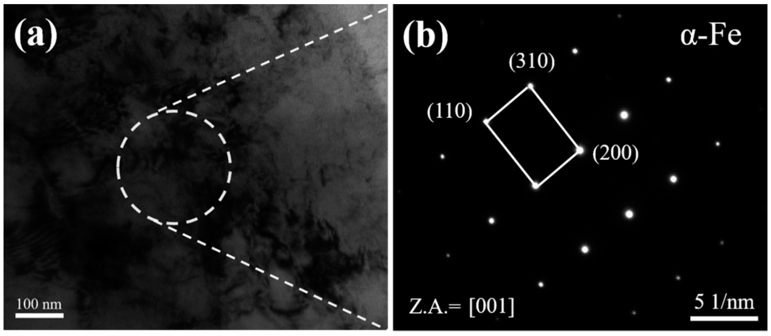
Figure 8.
The typical TEM images of the samples after PWHT with hold times of 20 h (a,b), and corresponding selected area electron diffraction (SAED) patterns of precipitated carbide (c).
Figure 8.
The typical TEM images of the samples after PWHT with hold times of 20 h (a,b), and corresponding selected area electron diffraction (SAED) patterns of precipitated carbide (c).
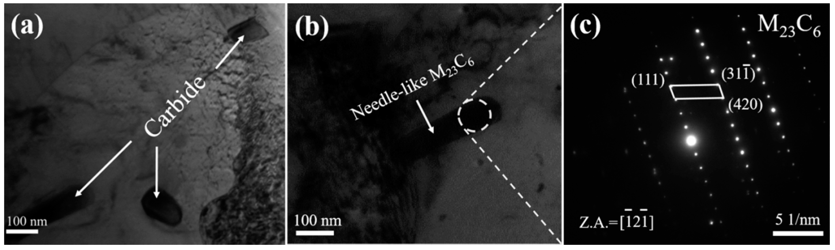
Figure 9.
HR-TEM images of the boundary between the precipitated carbides and the substrate, with the corresponding FFT results shown in the inset.
Figure 9.
HR-TEM images of the boundary between the precipitated carbides and the substrate, with the corresponding FFT results shown in the inset.

Table 1.
The composition of base metal and filler metals (BM: base metal; FM: filler metal).
| Elements | C | Si | Mn | P | S | Cr | Mo | Ni | V | Cu | Fe |
|---|---|---|---|---|---|---|---|---|---|---|---|
| BM | 0.24 | 0.05 | 0.20 | 0.004 | 0.003 | 2.36 | 0.76 | 2.23 | 0.07 | <0.17 | Balance |
| FM | 0.094 | 0.23 | 1.42 | <0.010 | 0.002 | 0.56 | 0.52 | 2.20 | <0.01 | 0.059 | Balance |
Table 2.
The detailed welding process parameters.
| Parameters | Wire Diameter (mm) | Current (A) | Voltage (V) | Speed (mm/min) | Gas |
|---|---|---|---|---|---|
| - | 1.0 | 270 | 11.2 | 70 | Ar 99.999% 20/30 |
© 2018 by the authors. Licensee MDPI, Basel, Switzerland. This article is an open access article distributed under the terms and conditions of the Creative Commons Attribution (CC BY) license (http://creativecommons.org/licenses/by/4.0/).
Share and Cite
MDPI and ACS Style
Liu, X.; Cai, Z.; Yang, S.; Feng, K.; Li, Z. Characterization on the Microstructure Evolution and Toughness of TIG Weld Metal of 25Cr2Ni2MoV Steel after Post Weld Heat Treatment. Metals 2018, 8, 160. https://doi.org/10.3390/met8030160
AMA Style
Liu X, Cai Z, Yang S, Feng K, Li Z. Characterization on the Microstructure Evolution and Toughness of TIG Weld Metal of 25Cr2Ni2MoV Steel after Post Weld Heat Treatment. Metals. 2018; 8(3):160. https://doi.org/10.3390/met8030160
Chicago/Turabian StyleLiu, Xia, Zhipeng Cai, Sida Yang, Kai Feng, and Zhuguo Li. 2018. "Characterization on the Microstructure Evolution and Toughness of TIG Weld Metal of 25Cr2Ni2MoV Steel after Post Weld Heat Treatment" Metals 8, no. 3: 160. https://doi.org/10.3390/met8030160
Note that from the first issue of 2016, this journal uses article numbers instead of page numbers. See further details here.