Analysis of Microstructure and Chip Formation When Machining Ti-6Al-4V


Abstract
1. Introduction
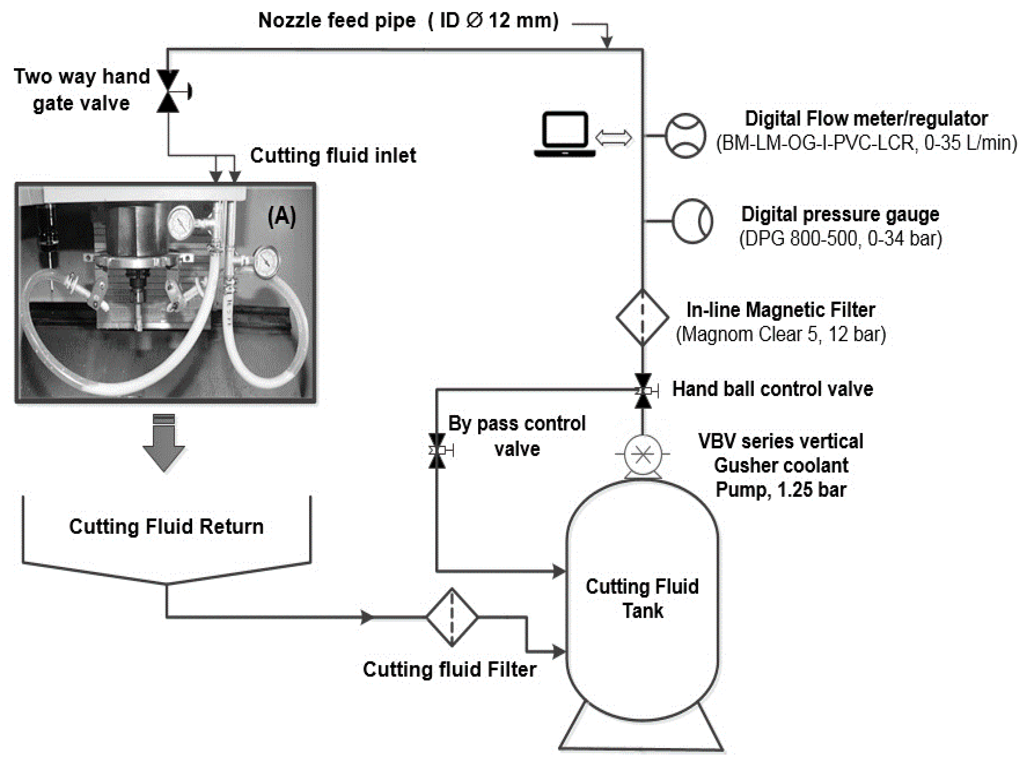
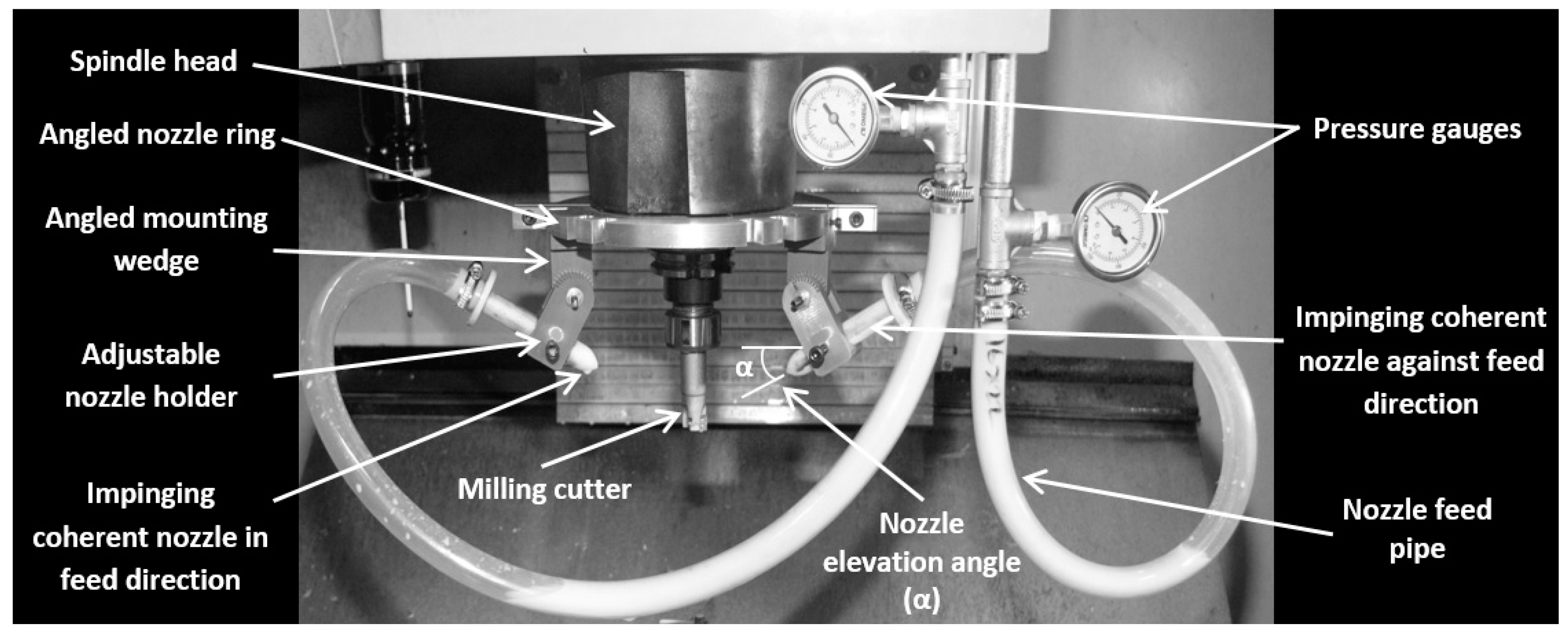
2. Design of the New Controlled Cutting Fluid Impinging Supply System (Cut-List)
3. Determination of Parameters of the Fluid Supply System
4. Experimental Work
5. Results and Discussion
6. Conclusions
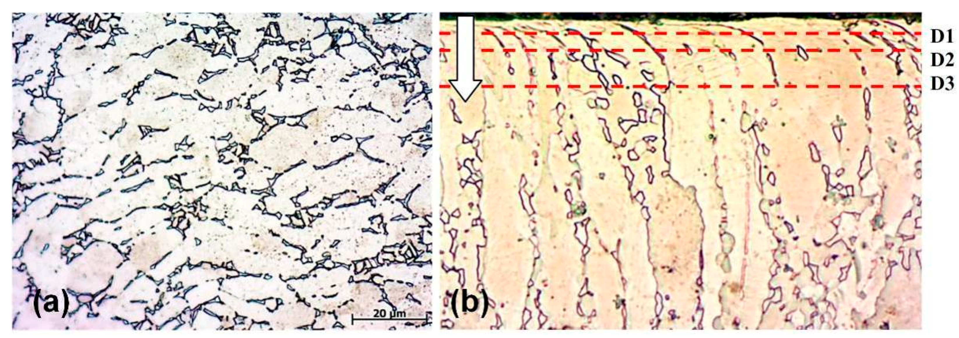
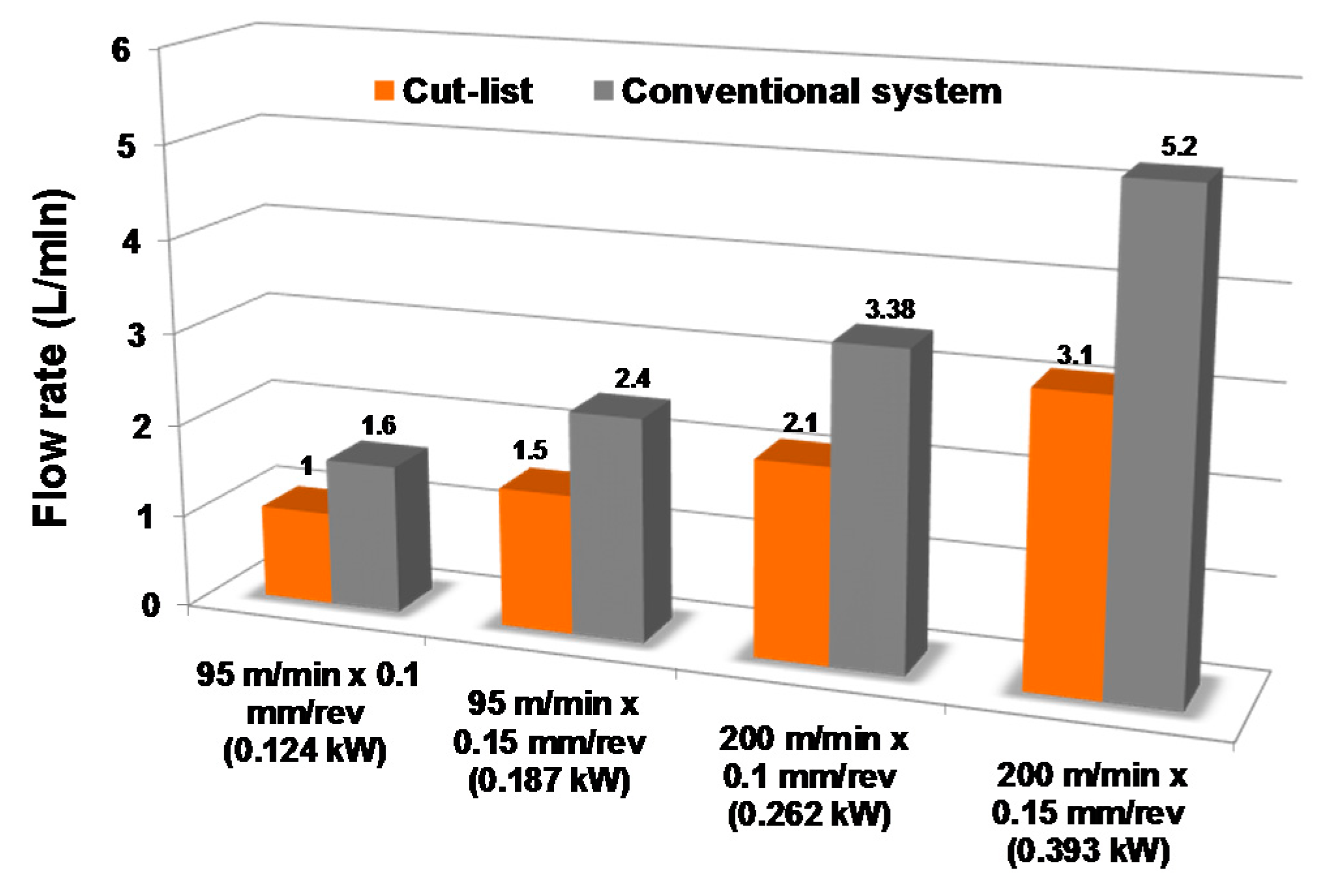
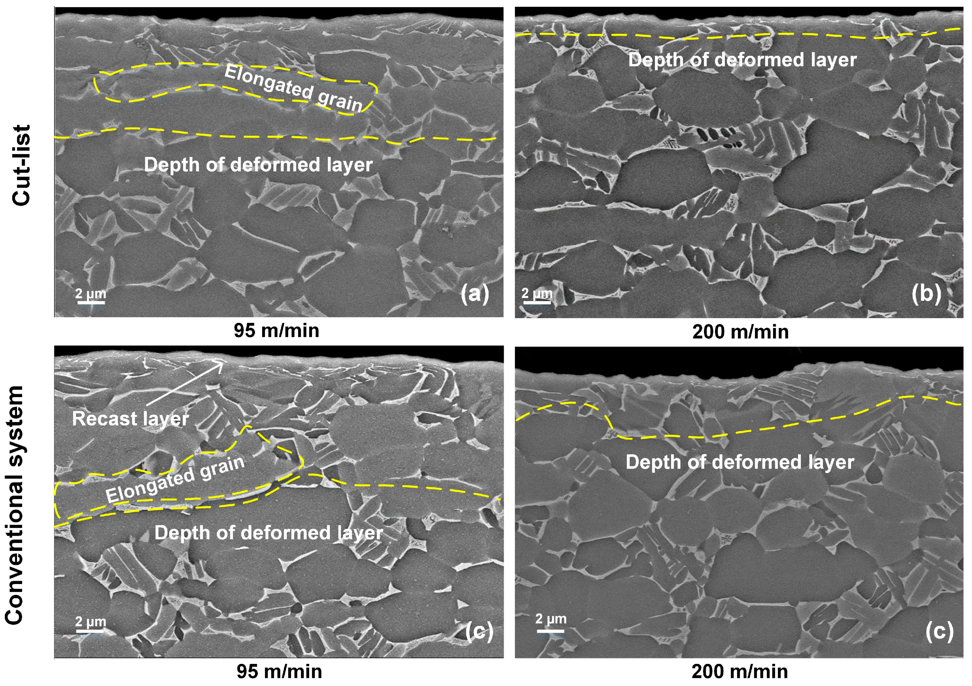
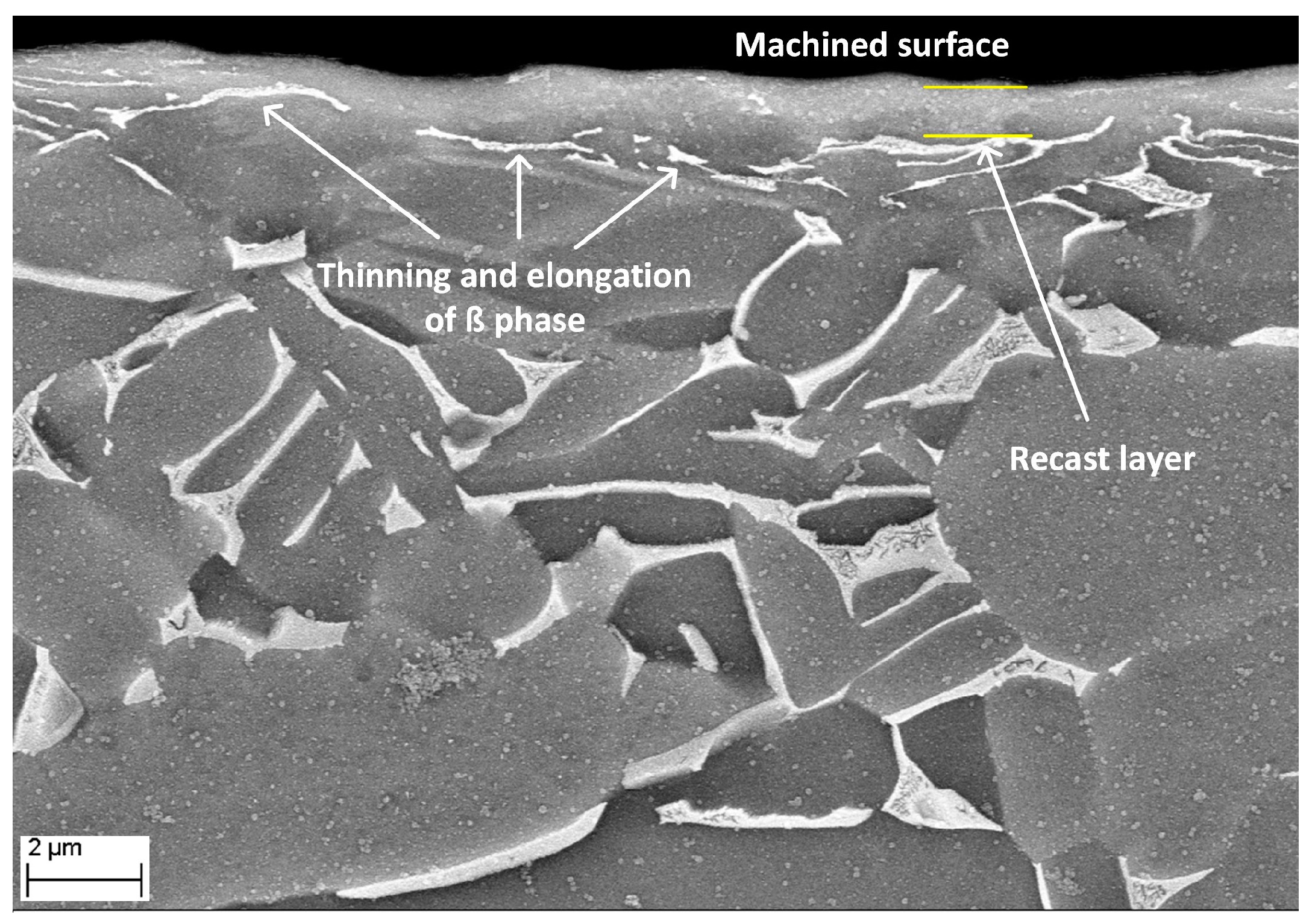
- Despite the dramatic drop in cutting fluid consumption provided by Cut-list (~42%), less microstructural alteration and a smaller deformed layer below the machined surfaces were observed.
- Cutting speed was a critical factor affecting microstructure, while the increase in cutting fluid flow rate with increasing cutting speeds has helped to mitigate microstructural damage.
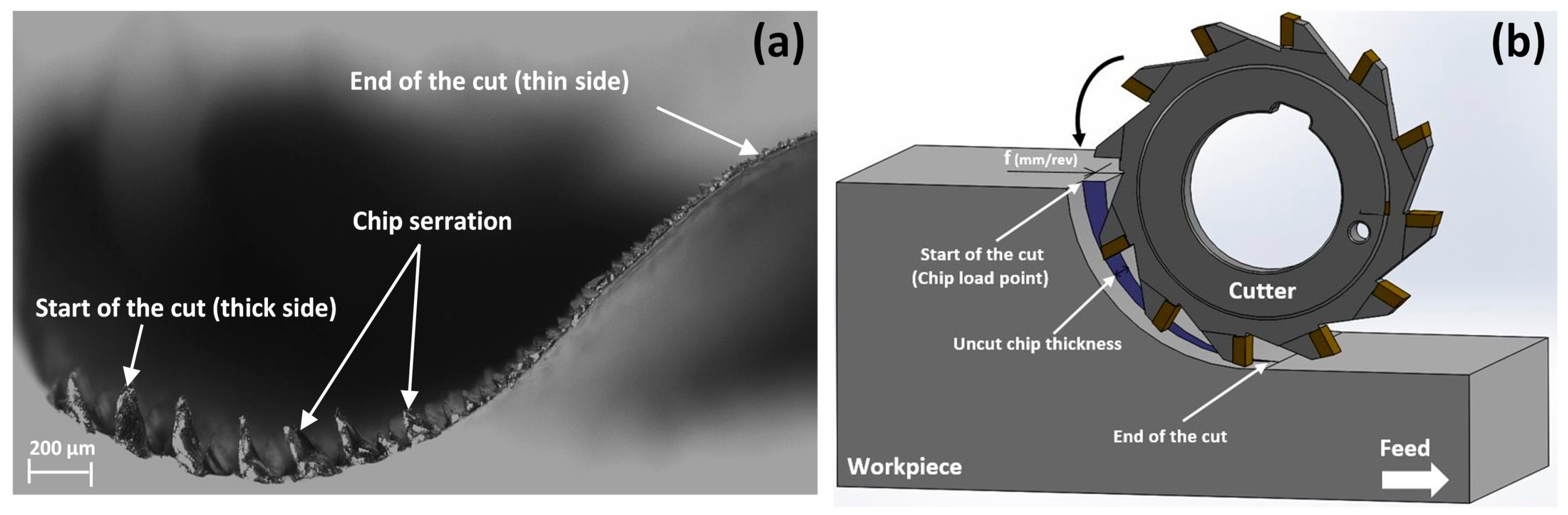
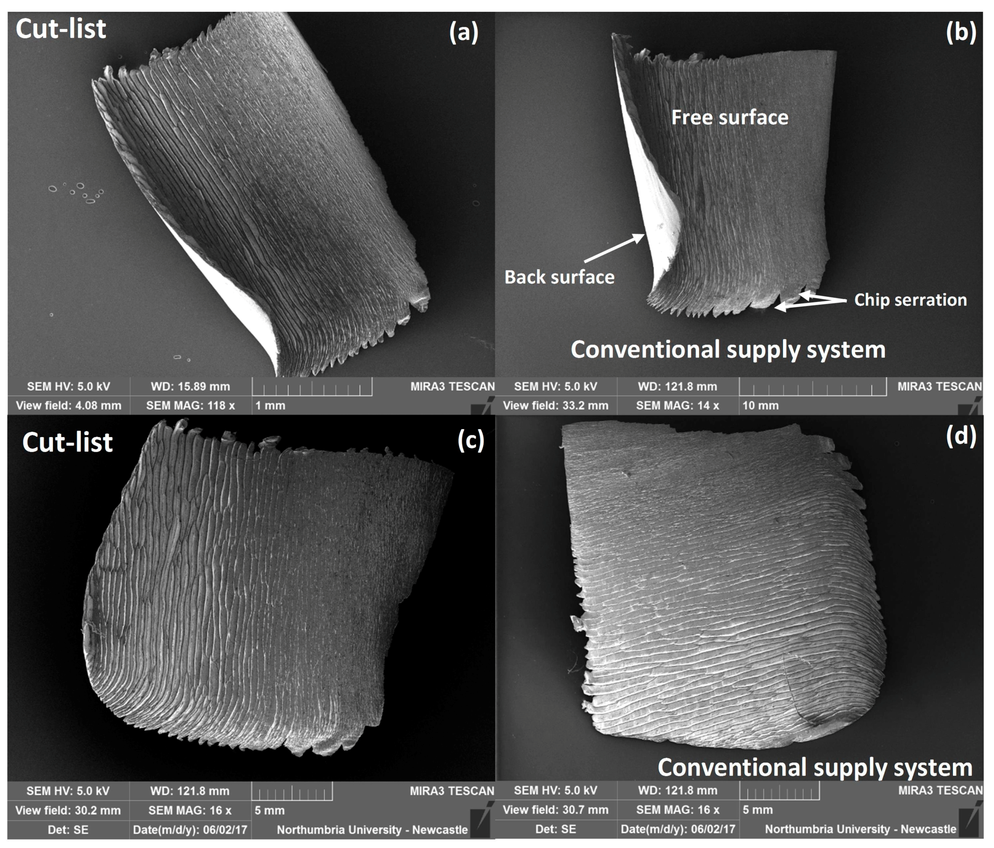
- The formation of discontinuous serrated chips is a fundamental characteristic of the down-milling of Ti-6Al-4V with both supply systems under all conditions investigated.
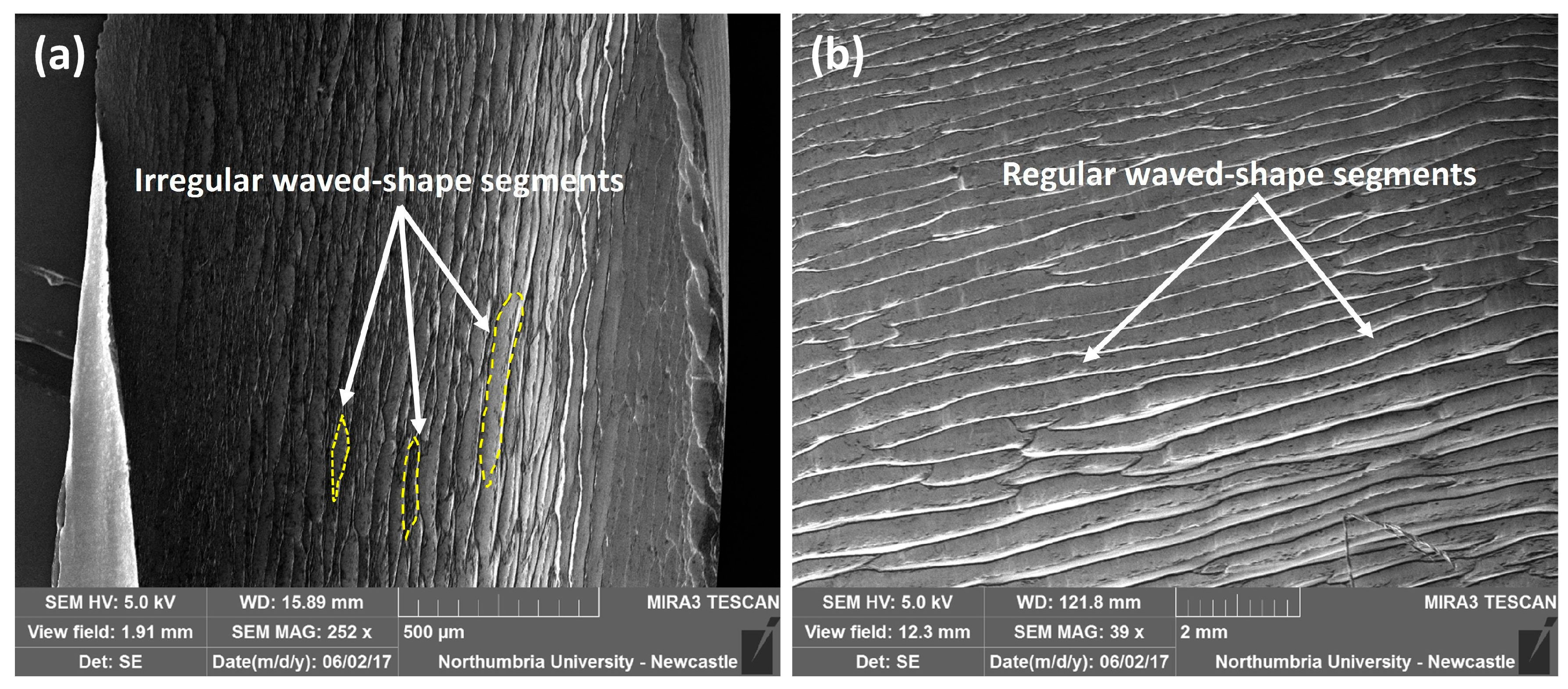
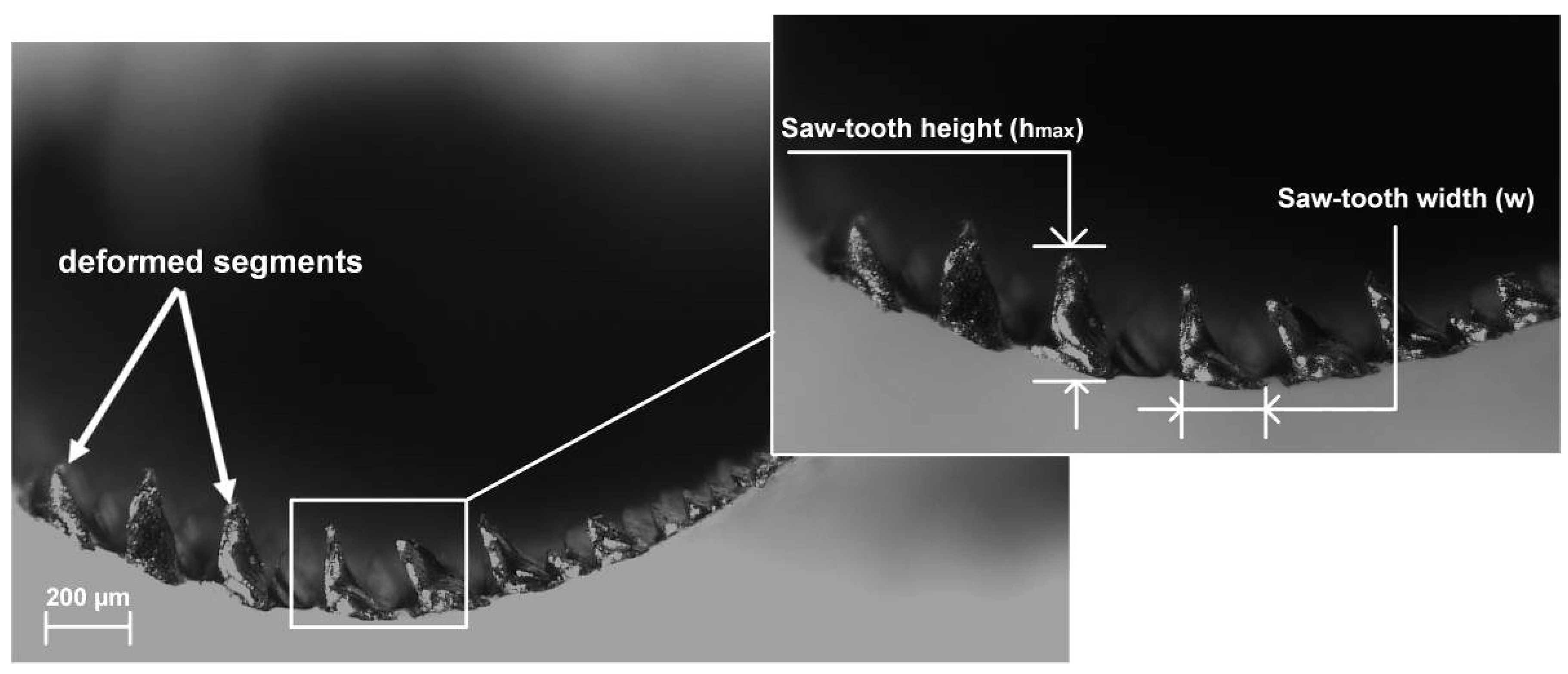
- The free surfaces of all chips generated are characterised by highly deformed wave like-shaped segments, while smooth back surfaces were observed.
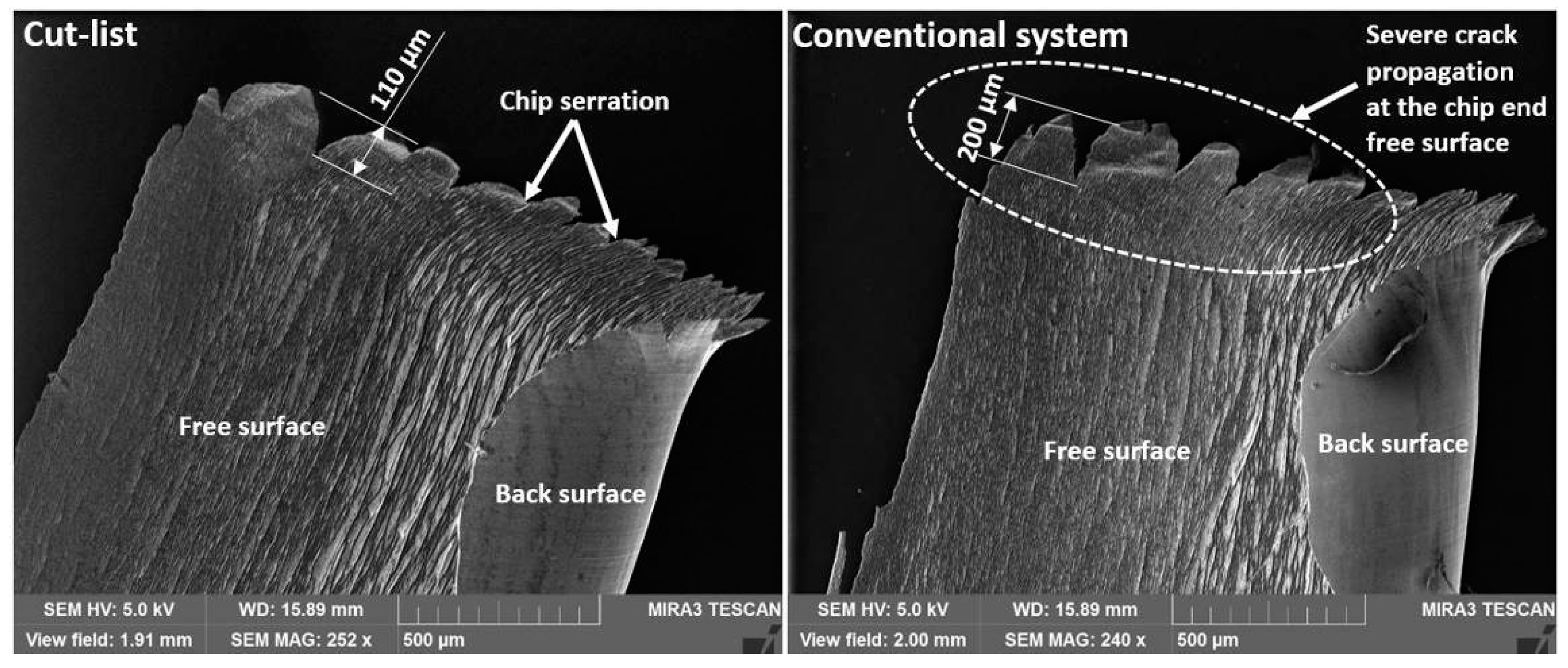
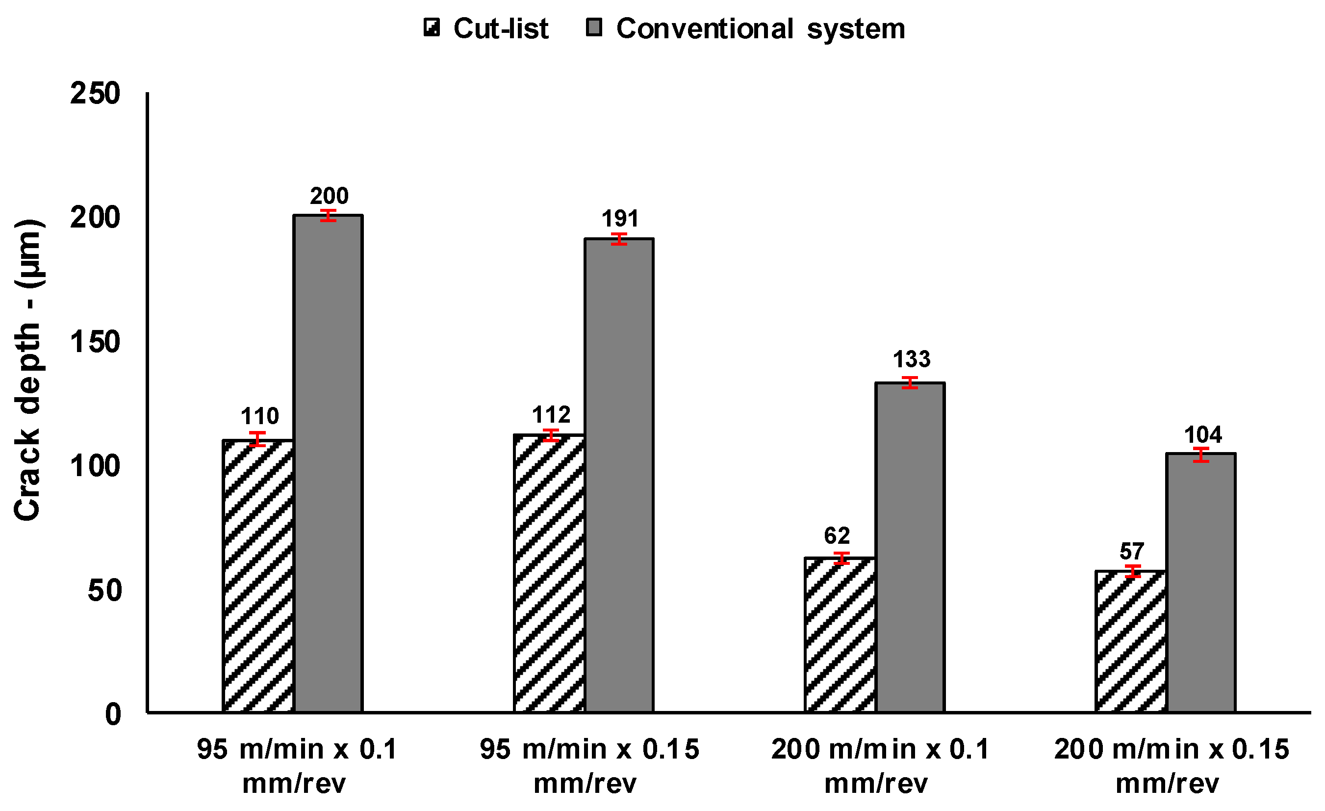
- Large crack/serration depths of approximately 200 µm at the end of the chip free surface were observed with the use of the conventional system, compared with only 110 µm for chips produced by Cut-list.
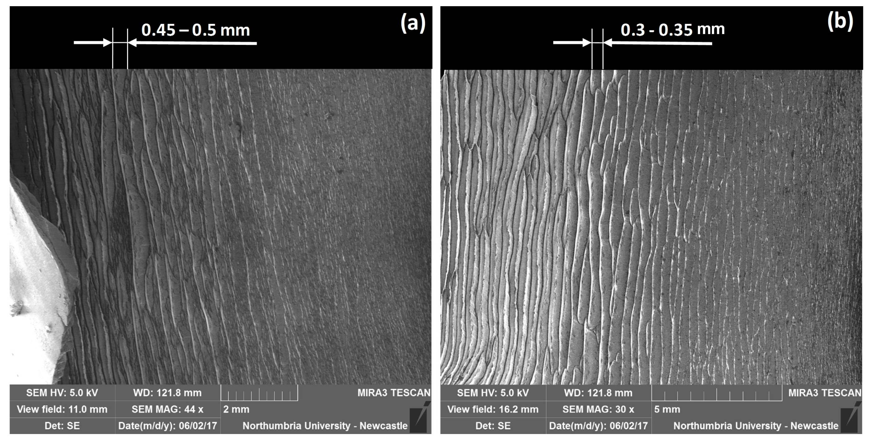
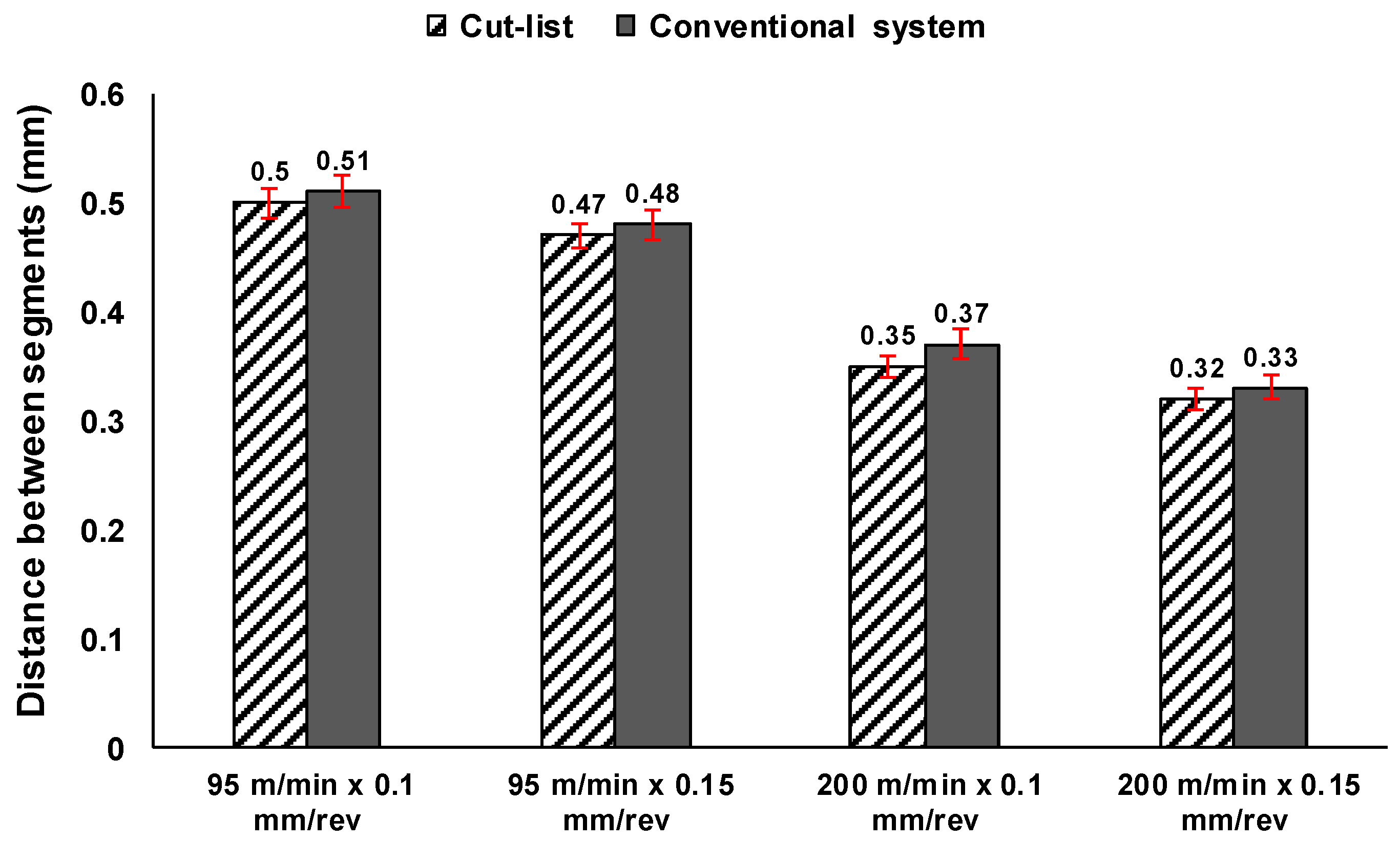
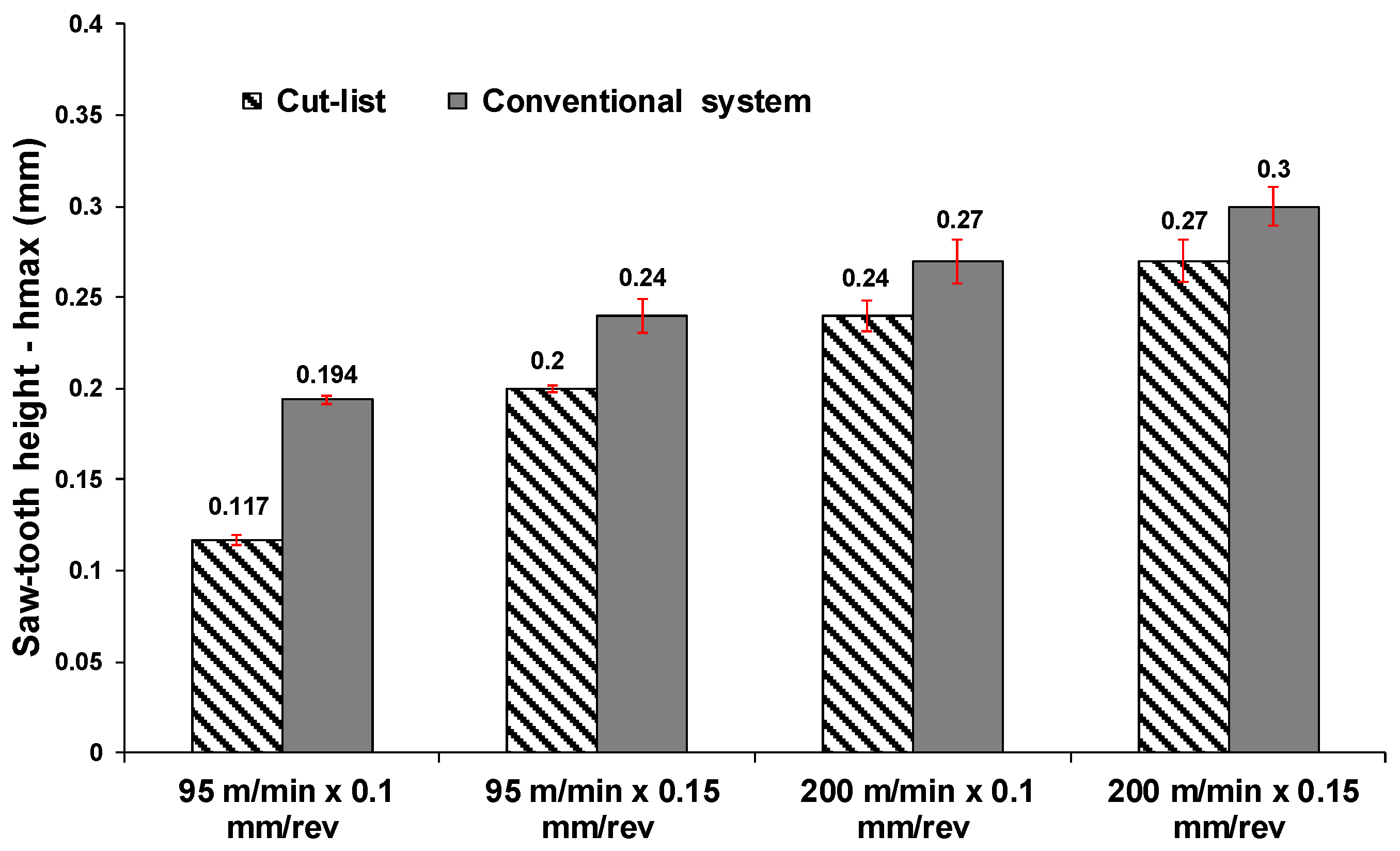
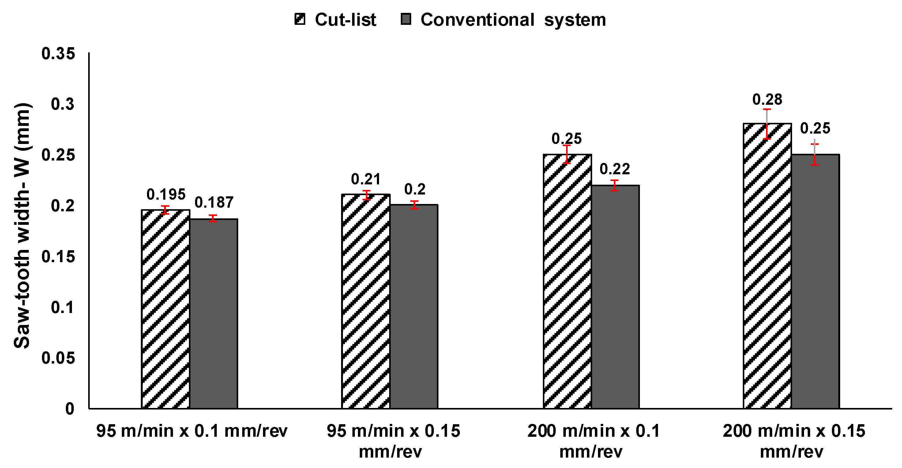
- Cut-list showed decreases of up to 12.5% in chip saw-tooth height (hmax) and increases of up to 13.63% in segment width. Segment width was considerably influenced by the volume of fluid supplied to the machining zone, while cutting speed and feed rate played vital roles in the transition from serrated chip formation.
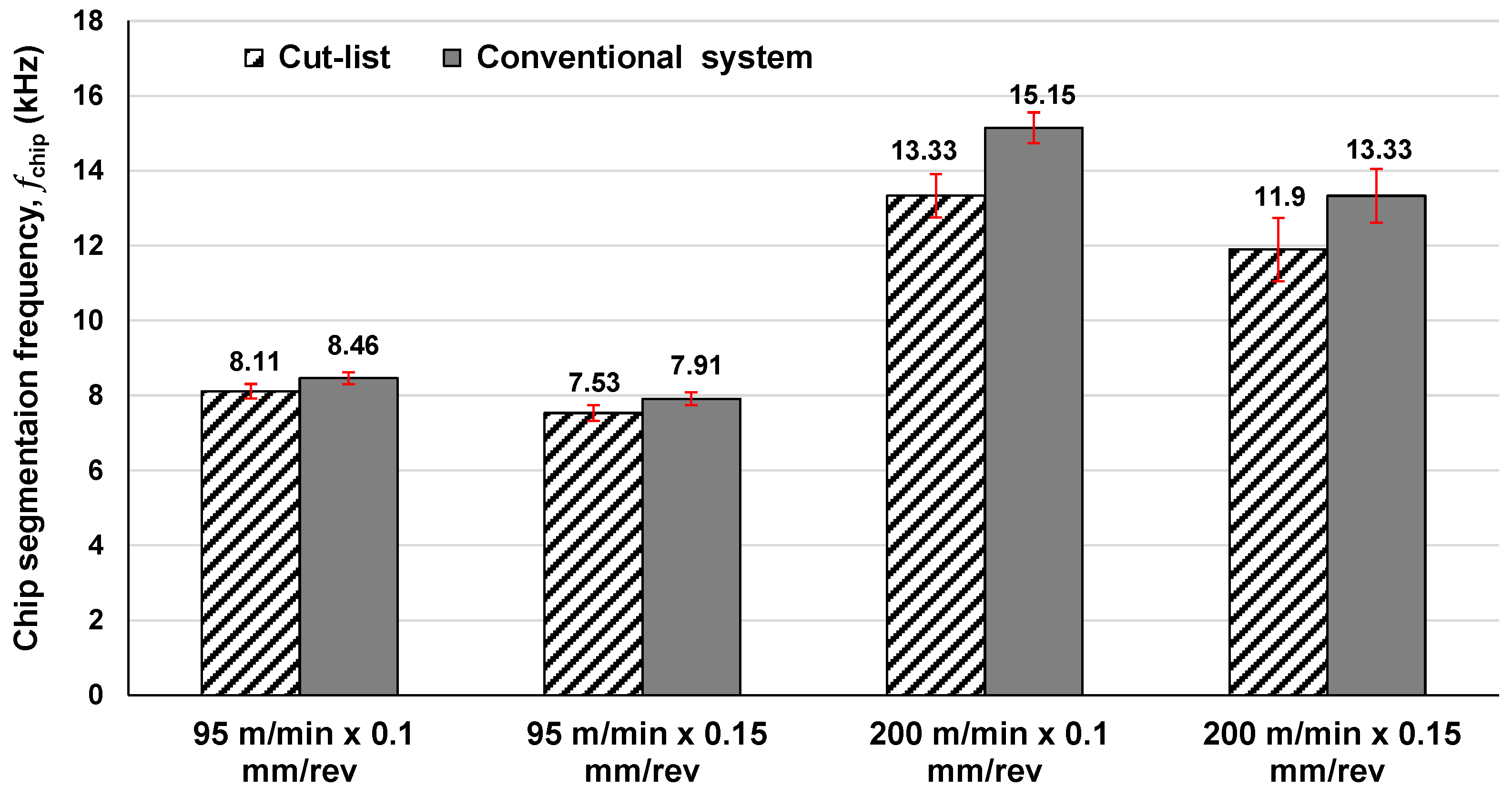
- Increased cutting speed led to increased chip segmentation frequency, while both fluid supply systems presented a typical frequency range of 7.53–15.15 kHz.
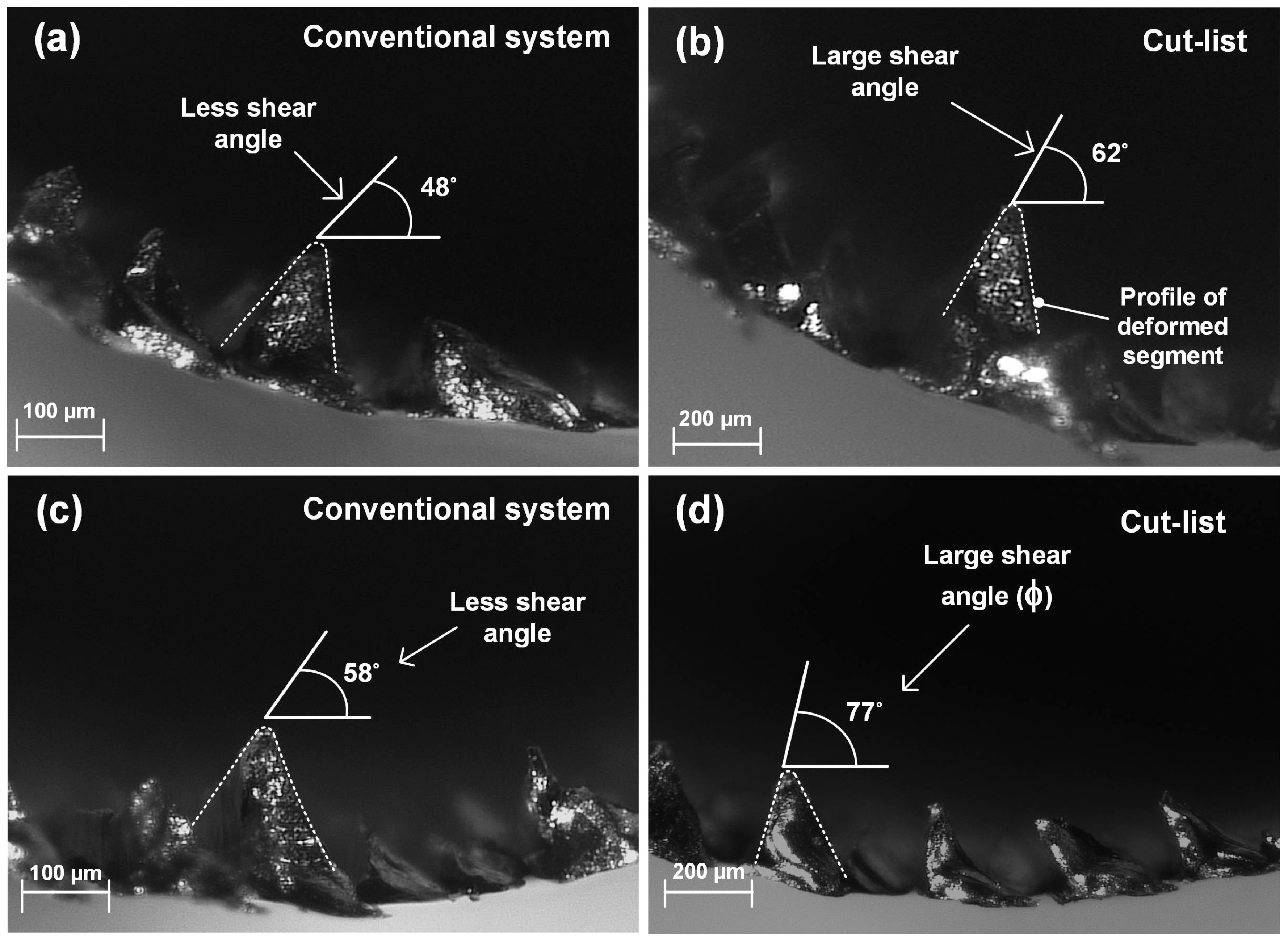
- Shear angle (φ) is very sensitive to cutting speed, and larger shear angles were observed when Cut-list was used.
Acknowledgments
Author Contributions
Conflicts of Interest
References
- Byers, J.P. Metalworking Fluids, 2nd ed.; CRC Press: Hoboken, NJ, USA, 2006; pp. 57–104. [Google Scholar]
- Gariani, S.; Shyha, I.; Inam, F.; Huo, D. Evaluation of a novel controlled cutting fluid impinging supply system when machining titanium alloys. Appl. Sci. 2017, 7, 560. [Google Scholar] [CrossRef]
- Gariani, S.; Shyha, I.; Inam, F.; Huo, D. Experimental analysis of system parameters for minimum cutting fluid consumption when machining Ti-6Al-4V using a novel supply system. Int. J. Adv. Manuf. Technol. 2018, 95, 2795–2809. [Google Scholar] [CrossRef]
- Ginting, A.; Nouari, M. Surface integrity of dry machined titanium alloys. Int. J. Mach. Tools Manuf. 2009, 49, 325–332. [Google Scholar] [CrossRef]
- Ulutan, D.; Ozel, T. Machining induced surface integrity in titanium and nickel alloys: A review. Int. J. Mach. Tools Manuf. 2011, 51, 250–280. [Google Scholar] [CrossRef]
- Che-Haron, C.H.; Jawaid, A. The effect of machining on surface integrity of titanium alloy Ti–6% Al–4% V. J. Mater. Process. Technol. 2005, 166, 188–192. [Google Scholar] [CrossRef]
- Velásquez, J.P.; Tidu, A.; Bolle, B.; Chevrier, P.; Fundenberger, J.-J. Sub-surface and surface analysis of high speed machined Ti-6Al-4V alloy. Mater. Sci. Eng. A 2010, 527, 2572–2578. [Google Scholar] [CrossRef]
- Rahim, E.A.; Sharif, S. Investigation on tool life and surface integrity when drilling Ti-6Al-4V And Ti-5Al-4V-Mo/Fe. JSME Int. J. Ser. C Mech. Syst. Mach. Elements Manuf. 2006, 49, 340–345. [Google Scholar] [CrossRef]
- Antonialli, A.Í.S.; Diniz, A.E.; Neto, H.K. Tool life and machined surface damage on titanium alloy milling using different cooling-lubrication conditions. In Proceedings of the 20th International Congress of Mechanical Engineering, Gramado, Brazil, 15–20 November 2009. [Google Scholar]
- Ezugwu, E.O.; Bonney, J.; Da Silva, R.B.; Cakir, O. Surface integrity of finished turned Ti-6Al-4V alloy with pcd tools using conventional and high pressure coolant supplies. Int. J. Mach. Tools Manuf. 2007, 47, 884–891. [Google Scholar] [CrossRef]
- Moussaoui, K.; Mousseigne, M.; Senatore, J.; Chieragatti, R.; Monies, F. Influence of milling on surface integrity of Ti6Al4V—Study of the metallurgical characteristics: Microstructure and microhardness. Int. J. Adv. Manuf. Technol. 2013, 1–13. [Google Scholar] [CrossRef]
- Edkins, K.D.; Rensburg, N.J.V.; Laubscher, R.F. Evaluating the subsurface microstructure of machined Ti-6Al-4V. Procedia CIRP 2014, 13, 270–275. [Google Scholar] [CrossRef]
- Mantle, A.L.; Aspinwall, D.K. Surface integrity of a high speed milled gamma titanium aluminide. J. Mater. Process. Technol. 2001, 118, 143–150. [Google Scholar] [CrossRef]
- Patil, A.; Sushil, I. Machining challenges in Ti-6Al-4V—A review. Int. J. Innov. Eng. Technol. 2015, 5, 6–23. [Google Scholar]
- Li, A.; Zhao, J.; Zhou, Y.; Chen, X.; Wang, D. Experimental investigation on chip morphologies in high-speed dry milling of titanium alloy Ti-6Al-4V. Int. J. Adv. Manuf. Technol. 2012, 62, 933–942. [Google Scholar] [CrossRef]
- Ducobu, F.; Rivière-Lorphèvre, E.; Filippi, E. Numerical contribution to the comprehension of saw-toothed Ti6Al4V chip formation in orthogonal cutting. Int. J. Mech. Sci. 2014, 81, 77–87. [Google Scholar] [CrossRef]
- Seshacharyulu, T.; Medeiros, S.; Morgan, J.; Malas, J.; Frazier, W.; Prasad, Y. Hot deformation and microstructural damage mechanisms in extra-low interstitial (ELI) grade Ti-6Al-4V. Mater. Sci. Eng. A 2000, 279, 289–299. [Google Scholar] [CrossRef]
- Calamaz, M.; Coupard, D.; Girot, F. A new material model for 2d numerical simulation of serrated chip formation when machining titanium alloy Ti-6Al-4V. Int. J. Mach. Tools Manuf. 2008, 48, 275–288. [Google Scholar] [CrossRef]
- Yang, Q.; Wu, Y.; Liu, D.; Chen, L.; Lou, D.; Zhai, Z.; Liu, Z. Characteristics of serrated chip formation in high-speed machining of metallic materials. Int. J. Adv. Manuf. Technol. 2016, 86, 1201–1206. [Google Scholar] [CrossRef]
- Sun, S.; Brandt, M.; Dargusch, M.S. Characteristics of cutting forces and chip formation in machining of titanium alloys. Int. J. Mach. Tools Manuf. 2009, 49, 561–568. [Google Scholar] [CrossRef]
- Bejjani, R.; Balazinski, M.; Attia, H.; Plamondon, P.; L’Éspérance, G. Chip formation and microstructure evolution in the adiabatic shear band when machining titanium metal matrix composites. Int. J. Mach. Tools Manuf. 2016, 109, 137–146. [Google Scholar] [CrossRef]
- Sutter, G.; Faure, L.; Molinari, A.; Ranc, N.; Pina, V. An experimental technique for the measurement of temperature fields for the orthogonal cutting in high speed machining. Int. J. Mach. Tools Manuf. 2003, 43, 671–678. [Google Scholar] [CrossRef]
- Zhang, X.; Shivpuri, R.; Srivastava, A. Role of phase transformation in chip segmentation during high speed machining of dual phase titanium alloys. J. Mater. Process. Technol. 2014, 214, 3048–3066. [Google Scholar] [CrossRef]
- Sutter, G.; List, G. Very high speed cutting of Ti-6Al-4V titanium alloy–change in morphology and mechanism of chip formation. Int. J. Mach. Tools Manuf. 2013, 66, 37–43. [Google Scholar] [CrossRef]
- Atlati, S.; Haddag, B.; Nouari, M.; Zenasni, M. Analysis of a new segmentation intensity ratio “SIR” to characterize the chip segmentation process in machining ductile metals. Int. J. Mach. Tools Manuf. 2011, 51, 687–700. [Google Scholar] [CrossRef]
- Kouadri, S.; Necib, K.; Atlati, S.; Haddag, B.; Nouari, M. Quantification of the chip segmentation in metal machining: Application to machining the aeronautical aluminium alloy AA2024-T351 with cemented carbide tools WC-Co. Int. J. Mach. Tools Manuf. 2013, 64, 102–113. [Google Scholar] [CrossRef]
- Harzallah, M.; Pottier, T.; Senatore, J.; Mousseigne, M.; Germain, G.; Landon, Y. Numerical and experimental investigations of ti-6al-4v chip generation and thermo-mechanical couplings in orthogonal cutting. Int. J. Mech. Sci. 2017, 134, 189–202. [Google Scholar] [CrossRef]
- Astakhov, V.P.; Shvets, S. The assessment of plastic deformation in metal cutting. J. Mater. Process. Technol. 2004, 146, 193–202. [Google Scholar] [CrossRef]
- Webster, J.A. Improving surface integrity and economics of grinding by optimum coolant application, with consideration of abrasive tool and process regime. J. Eng. Manuf. 2007, 221, 1665–1675. [Google Scholar] [CrossRef]
- Rowe, W.B.; Hitchnier, M. Handbook of Machining with Grinding, 2nd ed.; CRC Press: Hoboken, NJ, USA, 2007. [Google Scholar]
- Wang, F.; Zhao, J.; Li, A.; Zhao, J. Experimental study on cutting forces and surface integrity in high-speed side milling of Ti-6Al-4V titanium alloy. Mach. Sci. Technol. 2014, 18, 448–463. [Google Scholar] [CrossRef]
- Liu, J.; Ren, C.; Qin, X.; Li, H. Prediction of heat transfer process in helical milling. Int. J. Adv. Manuf. Technol. 2014, 72, 693–705. [Google Scholar] [CrossRef]
- Grzesik, W. Chapter nine—Heat in metal cutting. In Advanced Machining Processes of Metallic Materials, 2nd ed.; Elsevier: Oxford, UK, 2017; pp. 163–182. [Google Scholar]
- Sato, M.; Tamura, N.; Tanaka, H. Temperature variation in the cutting tool in end milling. J. Manuf. Sci. Eng. 2011, 133, 021005. [Google Scholar] [CrossRef]
- Cui, X.; Guo, J. Effects of cutting parameters on tool temperatures in intermittent turning with the formation of serrated chip considered. Appl. Thermal Eng. 2017, 110, 1220–1229. [Google Scholar] [CrossRef]
- Aerospace-Kennametal. Titanium Machining Guide. Available online: https://www.kennametal.com/content/dam/kennametal/kennametal/common/Resources/Catalogs-Literature/Metalworking/Titanium_material_machining_guide_Aerospace.pdf (accessed on 15 April 2016).
- Morgan, M.; Baines-Jones, V. On the coherent length of fluid nozzles in grinding. Key Eng. Mater. 2009, 404, 61–67. [Google Scholar] [CrossRef]
- Patil, S.; Jadhav, S.; Kekade, S.; Supare, A.; Powar, A.; Singh, R.K.P. The influence of cutting heat on the surface integrity during machining of titanium alloy Ti6Al4V. Procedia Manuf. 2016, 5, 857–869. [Google Scholar] [CrossRef]
- da Silva, R.B.; Machado, Á.R.; Ezugwu, E.O.; Bonney, J.; Sales, W.F. Tool life and wear mechanisms in high speed machining of Ti-6Al-4V alloy with pcd tools under various coolant pressures. J. Mater. Process. Technol. 2013, 213, 1459–1464. [Google Scholar] [CrossRef]
- Gariani, S.; Shyha, I.; Inam, F.; Huo, D. Influence of vegetable oil-based controlled cutting fluid impinging supply system on micro hardness in machining of Ti-6Al-4V. Int. J. Chem. Mol. Nuclear Mater. Metall. Eng. 2017, 11, 316–321. [Google Scholar]
- Zou, B.; Chen, M.; Li, S. Study on finish-turning of NiCr20TiAl nickel-based alloy using Al2O3/TiN-coated carbide tools. Int. J. Adv. Manuf. Technol. 2011, 53, 81–92. [Google Scholar] [CrossRef]
- Ravi, S.; Pradeep Kumar, M. Experimental investigations on cryogenic cooling by liquid nitrogen in the end milling of hardened steel. Cryogenics 2011, 51, 509–515. [Google Scholar] [CrossRef]
- Pramanik, A. Problems and solutions in machining of titanium alloys. Int. J. Adv. Manuf. Technol. 2014, 70, 919–928. [Google Scholar] [CrossRef]
- Veiga, C.; Davim, J.; Loureiro, A. Review on machinability of titanium alloys: The process perspective. Rev. Adv. Mater. Sci. 2013, 34, 148–164. [Google Scholar]
- Amin, A.K.M.N.; Ismail, A.F.; Nor Khairusshima, M.K. Effectiveness of uncoated WC–Co and PCD inserts in end milling of titanium alloy—Ti-6Al-4V. J. Mater. Process. Technol. 2007, 192, 147–158. [Google Scholar] [CrossRef]
- Molinari, A.; Musquar, C.; Sutter, G. Adiabatic shear banding in high speed machining of Ti-6Al-4V: Experiments and modeling. Int. J. Plast. 2002, 18, 443–459. [Google Scholar] [CrossRef]
- Liu, H.; Zhang, J.; Jiang, Y.; He, Y.; Xu, X.; Zhao, W. Investigation on morphological evolution of chips for Ti6Al4V alloys with the increasing milling speed. Procedia CIRP 2016, 46, 408–411. [Google Scholar] [CrossRef]
- Daymi, A.; Boujelbene, M.; Salem, S.B.; Sassi, B.H.; Torbaty, S. Effect of the cutting speed on the chip morphology and the cutting forces. Arch. Comput. Mater. Sci. Surf. Eng. 2009, 1, 77–83. [Google Scholar]
- Barry, J.; Byrne, G.; Lennon, D. Observations on chip formation and acoustic emission in machining Ti-6Al-4V alloy. Int. J. Mach. Tools Manuf. 2001, 41, 1055–1070. [Google Scholar] [CrossRef]
- Rahman, M.; Senthil Kumar, A.; Salam, M.U. Experimental evaluation on the effect of minimal quantities of lubricant in milling. Int. J. Mach. Tools Manuf. 2002, 42, 539–547. [Google Scholar] [CrossRef]
- Zhao, Y.; Sun, J.; Li, J. Study on chip morphology and milling characteristics of laser cladding layer. Int. J. Adv. Manuf. Technol. 2015, 77, 783–796. [Google Scholar] [CrossRef]
- Mabrouki, T.; Belhadi, S.; Rigal, J.-F. Fundamental understanding of the segmented chip genesis for smart machining. A contribution in hard material turning. In Advances in Integrated Design and Manufacturing in Mechanical Engineering II; Springer: New York, NY, USA, 2007; pp. 443–459. [Google Scholar]
- Ezugwu, E.; Bonney, J.; Da Silva, R.; Machado, A.; Ugwoha, E. High productivity rough turning of Ti-6Al-4V alloy, with flood and high-pressure cooling. Tribol. Trans. 2009, 52, 395–400. [Google Scholar] [CrossRef]
- Patil, S.; Kekade, S.; Phapale, K.; Jadhav, S.; Powar, A.; Supare, A.; Singh, R. Effect of α and β phase volume fraction on machining characteristics of titanium alloy Ti6Al4V. Procedia Manuf. 2016, 6, 63–70. [Google Scholar] [CrossRef]
- Patil, S.; Joshi, S.; Tewari, A.; Joshi, S.S. Modelling and simulation of effect of ultrasonic vibrations on machining of Ti6Al4V. Ultrasonics 2014, 54, 694–705. [Google Scholar] [CrossRef] [PubMed]
- Joshi, S.; Pawar, P.; Tewari, A.; Joshi, S.S. Effect of β phase fraction in titanium alloys on chip segmentation in their orthogonal machining. CIRP J. Manuf. Sci. Technol. 2014, 7, 191–201. [Google Scholar] [CrossRef]
- Cotterell, M.; Byrne, G. Dynamics of chip formation during orthogonal cutting of titanium alloy Ti-6Al-4V. CIRP Ann. 2008, 57, 93–96. [Google Scholar] [CrossRef]
- Thamizhmanii, S.; Sulaiman, H. Machinability Study Using Chip Thickness Ratio on Difficult to Cut Metals by CBN Cutting Tool; Key Engineering Materials; Trans Tech Publ.: Zürich, Switzerland, 2012; pp. 1317–1322. [Google Scholar]


| Cutting Conditions | Corresponding Levels |
|---|---|
| Cutting speed (m/min) | 95, 200 |
| Feed rate (mm/rev) | 0.1, 0.15 |
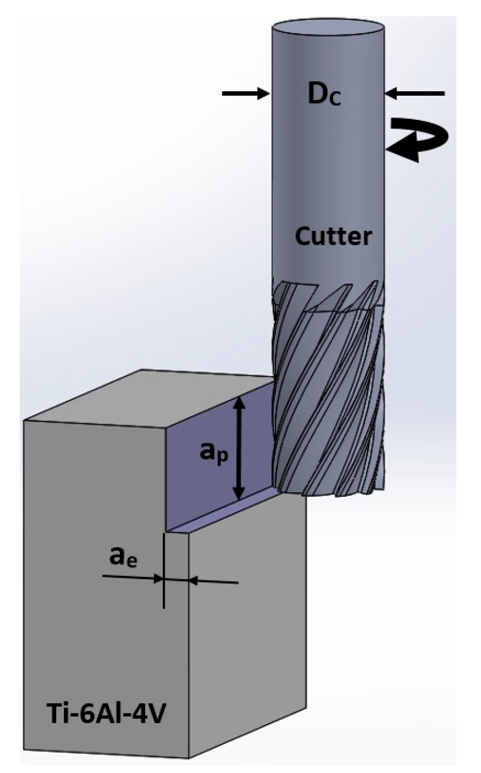
| Axial depth of cut, ap (mm) | 5 |
| Radial depth of cut, ae (mm) | 1.3 |
| Factor | Leve 1 | Level 2 | Level 3 |
|---|---|---|---|
| Nozzle angle in feed direction | 15° | 45° | 60° |
| Nozzle angle against feed direction | 15° | 45° | 60° |
| Nozzle impinging distance (mm) | 35 | 55 | 75 |
| Cutting speed (m/min) | 95 | 200 | - |
| Feed rate (mm/rev) | 0.1 | 0.15 | - |
© 2018 by the authors. Licensee MDPI, Basel, Switzerland. This article is an open access article distributed under the terms and conditions of the Creative Commons Attribution (CC BY) license (http://creativecommons.org/licenses/by/4.0/).
Share and Cite
Shyha, I.; Gariani, S.; El-Sayed, M.A.; Huo, D. Analysis of Microstructure and Chip Formation When Machining Ti-6Al-4V. Metals 2018, 8, 185. https://doi.org/10.3390/met8030185
Shyha I, Gariani S, El-Sayed MA, Huo D. Analysis of Microstructure and Chip Formation When Machining Ti-6Al-4V. Metals. 2018; 8(3):185. https://doi.org/10.3390/met8030185
Chicago/Turabian StyleShyha, Islam, Salah Gariani, Mahmoud Ahmed El-Sayed, and Dehong Huo. 2018. "Analysis of Microstructure and Chip Formation When Machining Ti-6Al-4V" Metals 8, no. 3: 185. https://doi.org/10.3390/met8030185
APA StyleShyha, I., Gariani, S., El-Sayed, M. A., & Huo, D. (2018). Analysis of Microstructure and Chip Formation When Machining Ti-6Al-4V. Metals, 8(3), 185. https://doi.org/10.3390/met8030185