Article

An Investigation of the Microstructure and Fatigue Behavior of Additively Manufactured AISI 316L Stainless Steel with Regard to the Influence of Heat Treatment

1
Institute of Materials Science and Engineering, TU Kaiserslautern, 67663 Kaiserslautern, Germany
2
State Materials Testing Institute Darmstadt (MPA), Chair and Institute for Materials Technology (IfW), Technische Universität Darmstadt, 64283 Darmstadt, Germany
3
Institute for Manufacturing Technology and Production Systems, TU Kaiserslautern, 67663 Kaiserslautern, Germany
*
Author to whom correspondence should be addressed.
Metals 2018, 8(4), 220; https://doi.org/10.3390/met8040220
Submission received: 23 February 2018 / Revised: 22 March 2018 / Accepted: 23 March 2018 / Published: 28 March 2018
(This article belongs to the Special Issue Additive Manufacturing of Ferrous Materials)

Abstract

:
To exploit the whole potential of Additive Manufacturing, it is essential to investigate the complex relationships between Additive Manufacturing processes, the resulting microstructure, and mechanical properties of the materials and components. In the present work, Selective Laser Melted (SLM) (process category: powder bed fusion), Laser Deposition Welded (LDW) (process category: direct energy deposition) and, for comparison, Continuous Casted and then hot and cold drawn (CC) austenitic stainless steel AISI 316L blanks were investigated with regard to their microstructure and mechanical properties. To exclude the influence of surface topography and focus the investigation on the volume microstructure, the blanks were turned into final geometry of specimens. The additively manufactured (AM-) blanks were manufactured in both the horizontal and vertical building directions. In the horizontally built specimens, the layer planes are perpendicular and in vertical building direction, they are parallel to the load axis of the specimens. The materials from different manufacturing processes exhibit different chemical composition and hence, austenite stability. Additionally, all types of blanks were heat treated (2 h, 1070 °C, H2O) and the influence of the heat treatment on the properties of differently manufactured materials were investigated. From the cyclic deformation curves obtained in the load increase tests, the anisotropic fatigue behavior of the AM-specimens could be detected with only one specimen in each building direction for the different Additive Manufacturing processes, which could be confirmed by constant amplitude tests. The results showed higher fatigue strength for horizontally built specimens compared to the vertical building direction. Furthermore, the constant amplitude tests show that the austenite stability influences the fatigue behavior of differently manufactured 316L. Using load increase tests as an efficient rating method of the anisotropic fatigue behavior, the influence of the heat treatment on anisotropy could be determined with a small number of specimens. These investigations showed no significant influence of the heat treatment on the anisotropic behavior of the AM-specimens.

Graphical Abstract

1. Introduction

Additive Manufacturing is a type of manufacturing technology, which builds three-dimensional objects by adding materials element by element or layer by layer [1,2]. This offers unique and novel approaches to product development and manufacturing. Additive Manufacturing enables the manufacturing of parts with complex geometries that are impractical or even impossible to manufacture by conventional manufacturing processes. Additively manufactured (AM-) parts can therefore make use of highly optimized lightweight lattice structures with specific weight saving porosities and internal stiffening structures, which can be tailored for individual applications [3,4,5]. A further benefit of Additive Manufacturing is the feasibility of manufacturing without part-specific tooling, which enables a cost efficient production of low volume parts or even customized products [6]. Additive Manufacturing also has the potential to reduce the complexity of process chains through function integration, to reduce the environmental footprint of the production [7], and it can be used as a repair technology for worn and damaged metal parts [8]. Additive Manufacturing also enables the possibility of a partial grading of the properties of materials, optimized with regard to the application [9].
Significant advancements have brought Additive Manufacturing technologies to an extent that they can be used not only for prototyping, but also for direct manufacturing of functional end-use parts. A wide range of materials is available including plastics, ceramics, composites, and metallic materials including, for example, tool steels, stainless steels, aluminum alloys, titanium alloys, nickel-based alloys, and so forth [10,11].
Two main categories of Additive Manufacturing processes for metal parts are powder bed fusion and direct energy deposition [12]. Two common Additive Manufacturing processes of these main categories are Selective Laser Melting (SLM) (process category: powder bed fusion) and Laser Deposition Welding (LDW) (process category: direct energy deposition). Both technologies use a laser beam as an energy source to fully melt metallic powder sequentially on a local scale to produce solid parts. SLM is a powder bed based technology, where the powder is spread evenly on the build platform. A computer controlled laser beam deflection mechanism diffracts the laser beam, which selectively scans the powder bed and thereby melts the powder. After the layer is complete, the build platform lowers the height of the layer thickness and a new layer of powder is spread evenly onto the platform. The LDW technology is characterized by creating a melt pool on the workpiece by a high energy laser beam. The powder, which is supplied in an inert gas stream by a nozzle, is fed into the melt pool and fused with the liquefied material [6].
To enable the whole potential of these manufacturing technologies, it is essential to get sound knowledge about the material’s properties of the AM-structures. Investigations of the microstructure and monotonic properties of the AM-materials are available in a large quantity. Microstructural investigations of Mower et al. [13], Yasa et al. [14], and Casati et al. [15] on selective laser melted austenitic stainless steel AISI 316L showed an elongation of grains along the building direction and visibility of the layer boundaries in light optical micrographs (LOMs), which is in accordance to the investigations of Brandl et al. [16] on laser deposition welded Ti6Al4V, Caiazzo et al. on laser powder bed fused Inconel 718 [17], and Bauer et al. [18] on the selective laser melted nickel based superalloy Haynes230®. Mower et al. [13] also observed this typical microstructure in AlSi10Mg. For the mentioned materials, Lewandowski et al. [10] described a similar tensile and 0.2% yield stress of AM-materials compared to conventionally manufactured materials and an anisotropic behavior of the AM-materials with regard to their building direction, which is in accordance to the observations of References [11,13,15,17,18,19]. In these investigations, the Horizontal building direction, in which layer planes are perpendicular to the load axis, showed higher values compared to the vertically built specimens.
To extend the application of Additive Manufacturing into the field of safety-relevant structural parts, it is indispensable to get comprehensive and reliable information about the fatigue properties of AM-materials. Investigations about this important aspect are available to a limited extent regarding fatigue life oriented and are even more limited regarding fatigue processes and cyclic deformation behavior. The available investigations of Günther et al. [20] show a decreased fatigue strength of the selective laser melted Ti6Al4V compared to conventionally manufactured material, which is mainly caused by the pores in AM-material resulting from binding defects. Investigations of Yadollahi et al. [19] on the stainless steel 17-4-PH and Mower et al. [13] on the austenitic stainless steel 316L and AlSi10Mg are in accordance to the observations of Reference [20] and show, additionally, an increased fatigue strength of AM-specimens in the horizontal building direction compared to the vertically built specimens. In accordance to these investigations, Leuders et al. [21] and Greitemeier et al. [22] on Ti6Al4V, and Stoffregen et al. [23] on 17-4-PH showed a high dependency of the fatigue strength of AM-specimens on microstructural defects, that is, pores.
For the reasons indicated above, in the present work, the microstructure and mechanical properties of Selective Laser Melted (SLM-) and Laser Deposition Welded (LDW-) materials were investigated. Additionally, Continuous Casted and then hot and cold drawn (CC-) material was investigated to get a comparison of the AM- to the conventionally manufactured materials. The focus of the investigations was the fatigue behavior of AM-materials, especially the influence of the following aspects:
  • the orientation of the load axis with respect to the building direction
  • the post Additive Manufacturing heat treatment (1070 °C, H2O), especially on anisotropy
  • the austenite stability, which is strongly affected by chemical composition
  • defects like pores or oxide inclusions resulting out of the Additive Manufacturing process
Therefore, microstructural investigations using light optical microscopy and scanning electron microscopy were conducted. The fatigue behavior was investigated via cyclic microindentation, load increase tests (LITs), and constant amplitude tests (CATs). LITs and CATs were performed with stress-strain measurement and in-situ high precision measurement of change in temperature and electrical resistance.

2. Materials

The present study extends the comparison of the microstructure, monotonic properties, and results of indentation tests of differently manufactured materials out of 316L in the as-built condition published in Reference [24] by investigations of the fatigue behavior and the influence of a post Additive Manufacturing heat treatment (HT). The specimens used in the present study are made of austenitic stainless steel AISI 316L (1.4404). The material is available as a conventional Continuous Casted and subsequently hot and cold drawn (CC-) material, but also widely used as ingot powder for Selective Laser Melting (SLM) and Laser Deposition Welding (LDW) processes. AISI 316L belongs to the widely used AISI 300 series austenitic stainless steels, that is, Fe-C-Cr-Ni alloys containing about 18 wt. % of Cr and 8 wt. % of Ni [25]. In this group, several austenitic steels are metastable, for example, AISI 304 and 348 [26,27], as well as 316L, which is considered in the present study. Therefore, thorough investigations of the monotonic and cyclic deformation induced phase transformations from paramagnetic austenite into a thermodynamically more stable microstructure—that is, paramagnetic ε-martensite and/or ferromagnetic α′-martensite—as well as their influences on the monotonic and cyclic properties were performed [26,27,28,29,30].
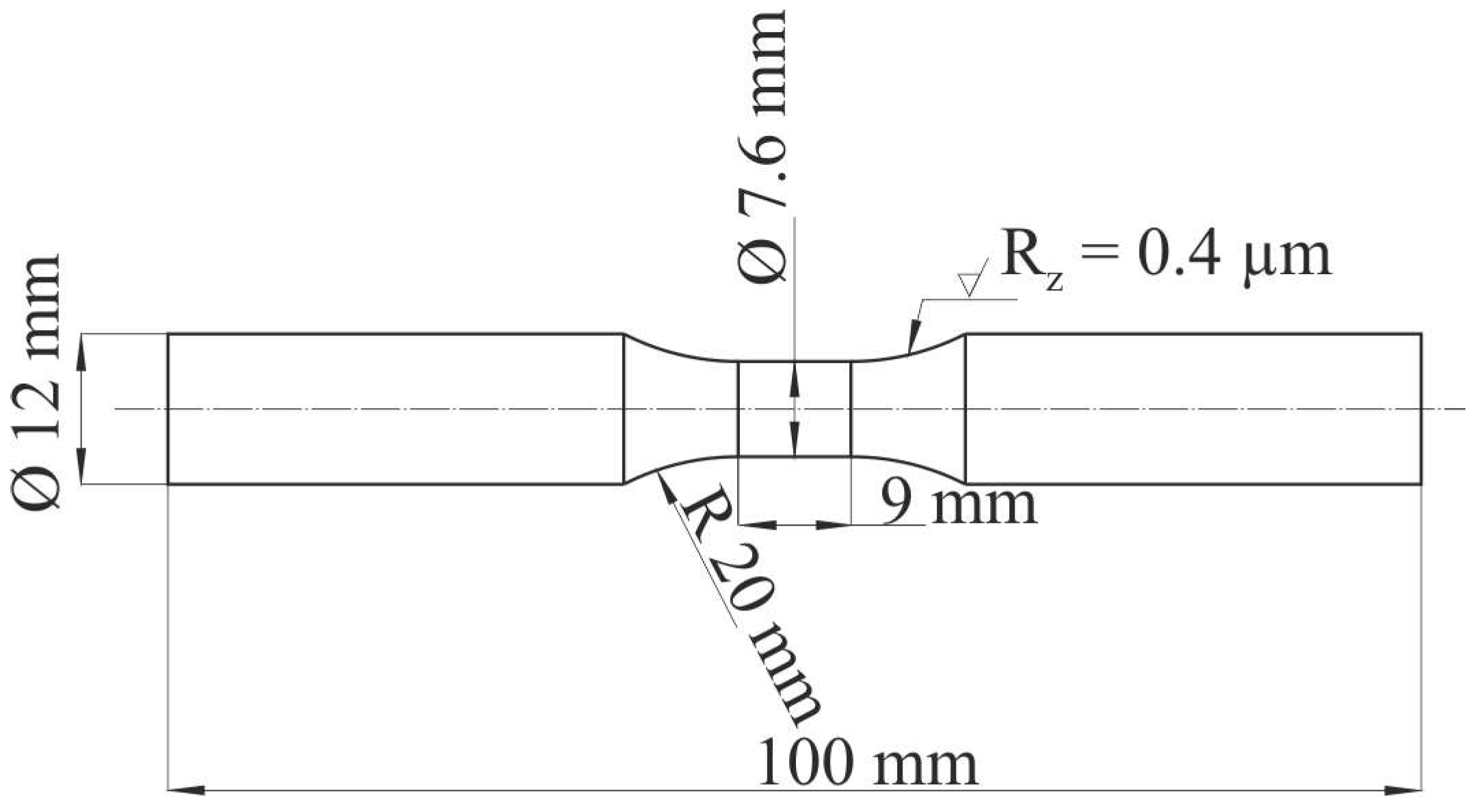
Tensile specimens were manufactured with a geometry according to DIN EN ISO 6892-1 [31] and a diameter in the gauge length of 8 mm. The geometry of the fatigue specimens is given in Figure 1. Note that all fatigue specimens were finally mechanically polished in the gauge length to a surface roughness of Rz = 0.4 µm.
To keep the Additive Manufacturing process simple and to exclude influences of surface topography on the test results for focusing the investigations on the volume microstructure, LDW-specimens were pre-manufactured as cuboids and afterward turned to their final geometrical shapes. Similarly, the SLM-specimens were pre-manufactured with cylindrical geometry and afterward turned to their final shape (see Table 1). Compared to SLM, the layer thickness was ten times larger in the LDW process. The average particle size of the ingot powder is bigger for the LDW than for the SLM process (see Table 1), and the particle size distribution shows a larger scatter of the LDW ingot material. To investigate the influence of the building direction in Additive Manufacturing processes on the material’s properties, blanks were manufactured in the vertical (LDW-V and SLM-V) as well as horizontal (LDW-H and SLM-H) building directions. Note that in the vertical building direction the layer planes are oriented perpendicular and in the horizontal building direction the layer planes are oriented parallel to the loading direction of the specimens. These two building directions were chosen for comparison of most different orientations possible. The CC-reference-specimens were manufactured by turning from continuous casted and then hot and cold drawn bars with a diameter of 15 mm.
To investigate the influence of a heat treatment on the microstructure and mechanical properties of AM-specimens, some blanks from each manufacturing process were heat treated in a resistance furnace (Nabertherm GmbH, Lilienthal, Germany) at ambient air. According to the typical parameters for austenitic steels given in Reference [26] and based on a parameter study within the present research, the material was solution annealed at 1070 °C for 2 h and afterwards quenched in water. After the heat treatment, the blanks were turned to the final specimen geometry (see Figure 1). Hence, four specimen variants were tested for each Additive Manufacturing process: the vertical and horizontal building direction and each in an as-built and heat treated condition.
The chemical compositions of the investigated AISI 316L austenitic stainless steel (1.4404) batches, determined by spectrophotometric analysis, are given in Table 2. All batches meet the specifications given in ASTM A 182/A 182M-14a [32]. However, it should be noted that chromium, nitrogen, nickel contents and, hence, austenite stability, evaluated by the Md30,Angel-temperatures (Equation (1) [28]), differ significantly.
Md30,Angel = 413 − 462 (C + N) − 9.2Si − 8.1Mn − 13.7Cr − 9.5Ni − 18.5Mo.
Note that Md30,Angel represents the temperature where 50% of the initial austenite transforms to α′-martensite, when subjected to a plastic strain of 30%. Lower Md30,Angel-temperatures indicate higher austenite stability. From Table 2, it becomes obvious that both AM-materials show distinctly higher austenite stability compared to the CC-material.

3. Experimental Methods

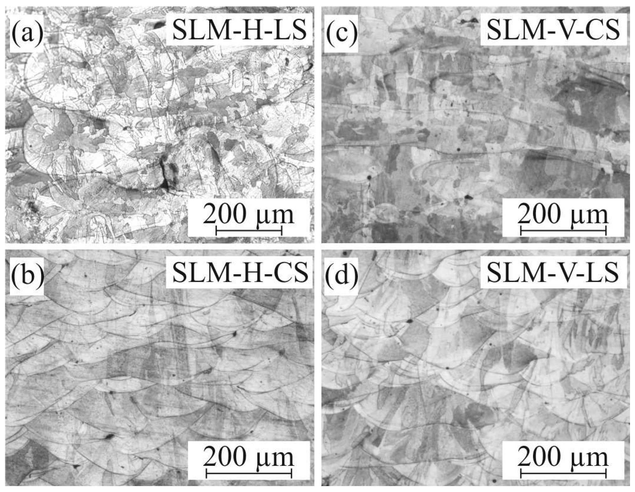
Light optical micrographs (LOMs) were taken with a Leica DM 6000 M device (Leica, Mannheim, Germany). SLM- and CC-samples were etched using V2A etchant while for the LDW-samples, Adler etchant was used, which leads to a better visualization of the microstructure of LDW-material with lower chromium and higher nitrogen content. Scanning electron microscopy (SEM) was performed using an FEI Quanta 600 device (FEI, Hillsboro, OR, USA). Microhardness measurements and cyclic microindentation tests were conducted with a Fischerscope H100 C device (Helmut Fischer GmbH, Sindelfingen, Germany). Macrohardness measurements were performed on a Zwick/Roell ZHU250 top device (Zwick Roell, Ulm, Germany) in the center of the cross-sections of the fatigue specimen shafts.
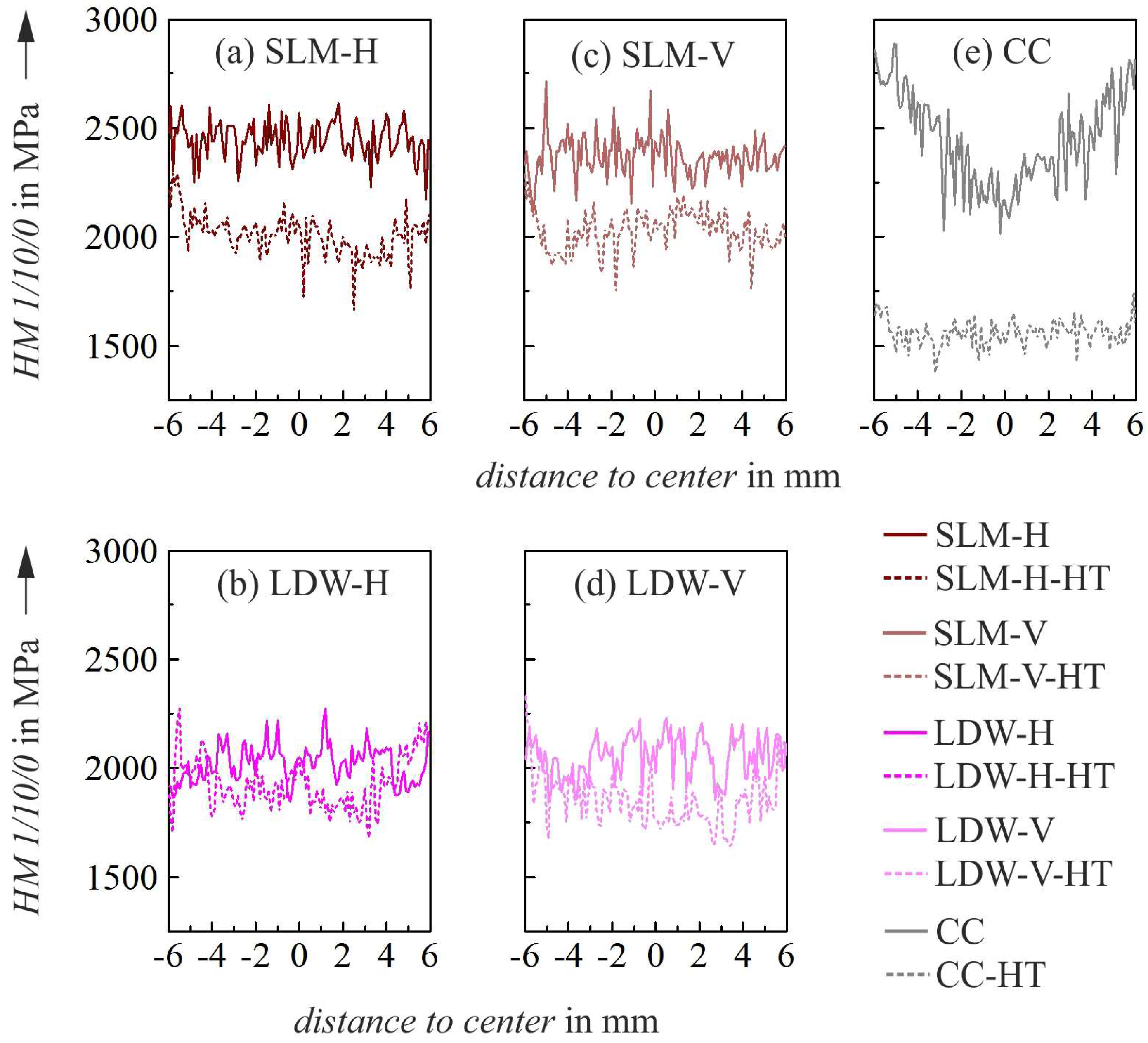
Microhardness line scans were determined with 120 indentations with a point to point distance of 100 µm and a minimum distance to the sample edge of 50 µm (see Figure 2), in the cross-sections of the shafts of two different fatigue specimens, which show, within tight tolerances, the same results.
Tensile tests were performed on a Zwick/Roell Z250 electromechanical testing device (Zwick Roell, Ulm, Germany) with a testing procedure according to DIN EN ISO 6892-1 [31].
The cyclic hardening potential of the differently manufactured microstructures has been determined by the PhyBaLCHT method similar to the work of Kramer et al. [
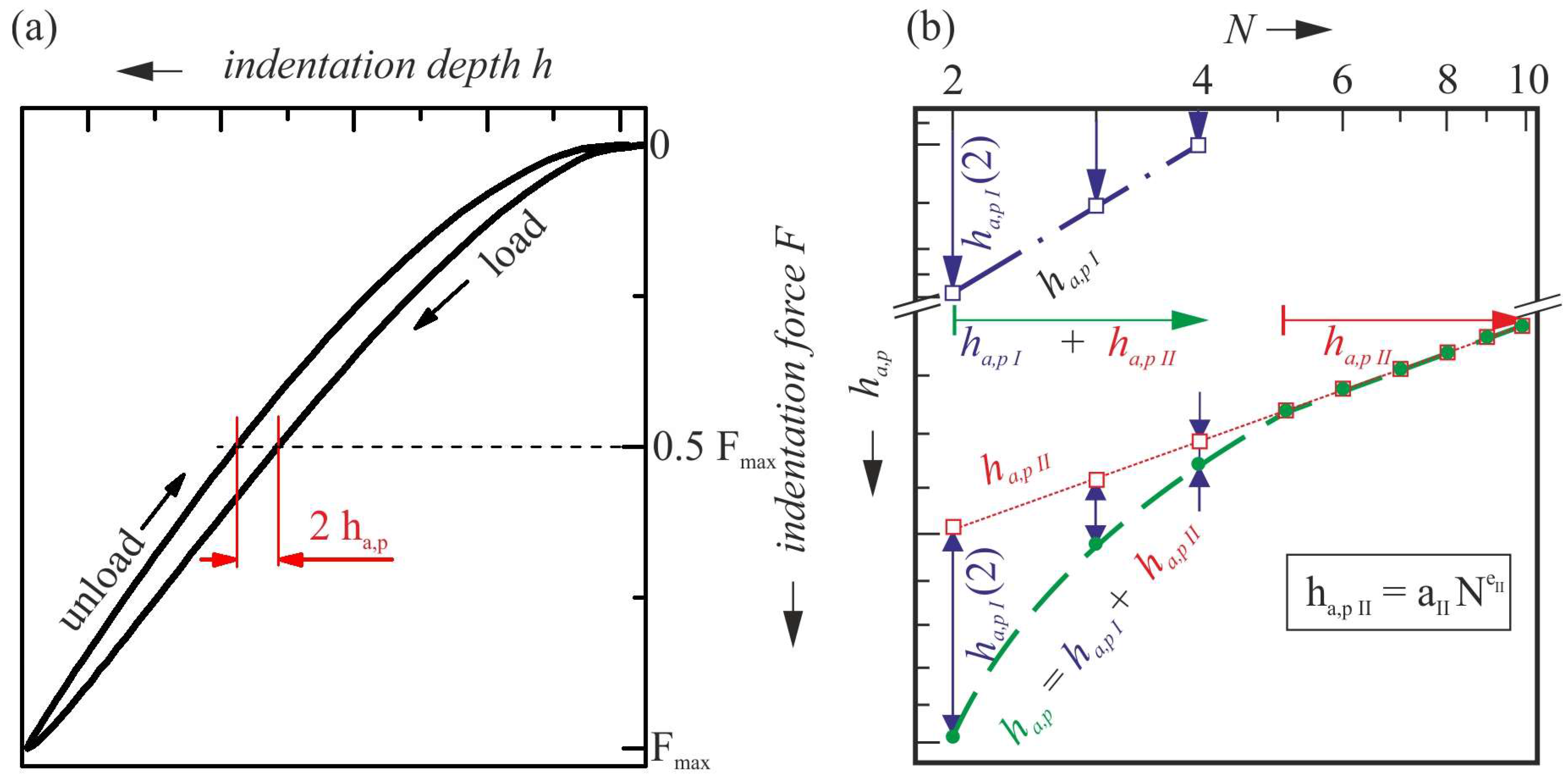
33]. Cyclic microindentation tests were conducted using a Vickers indenter on a planar material surface at 20 different positions in the middle of the cross-sections of the fatigue specimen shafts and were performed at two different samples, resulting in values, which differed less than 5%. At each position, 10 indentation cycles with a cosine waveform, a maximum load of 1000 mN, and a frequency of 1/12 Hz were performed. Up from the second cycle, the load-indentation depth-relation forms a hysteresis loop. The half width of the hysteresis at the mean load was determined as the plastic indentation depth amplitude ha,p (see Figure 3a). The ha,p-N-relation can be described from the 5th to the 10th cycle by a power law function (see Figure 3b). The differences of the ha,p-values to the power law ha,p II between the 2nd and 4th cycle can be described by a further power law representing ha,p I. The sum of both power laws describes the whole ha,p-N-relation. Due to the fact that ha,p II is part of both power laws and that after the 4th cycle, significant macroplastic deformation processes are mainly completed, indicated by the slope change of the ha,p-N-curve, the exponent of the second power law can be considered representative for the cyclic behavior of the material [33]. The exponent of the power law describes the hardening potential of the material and is called cyclic hardening exponentCHT eII [33].
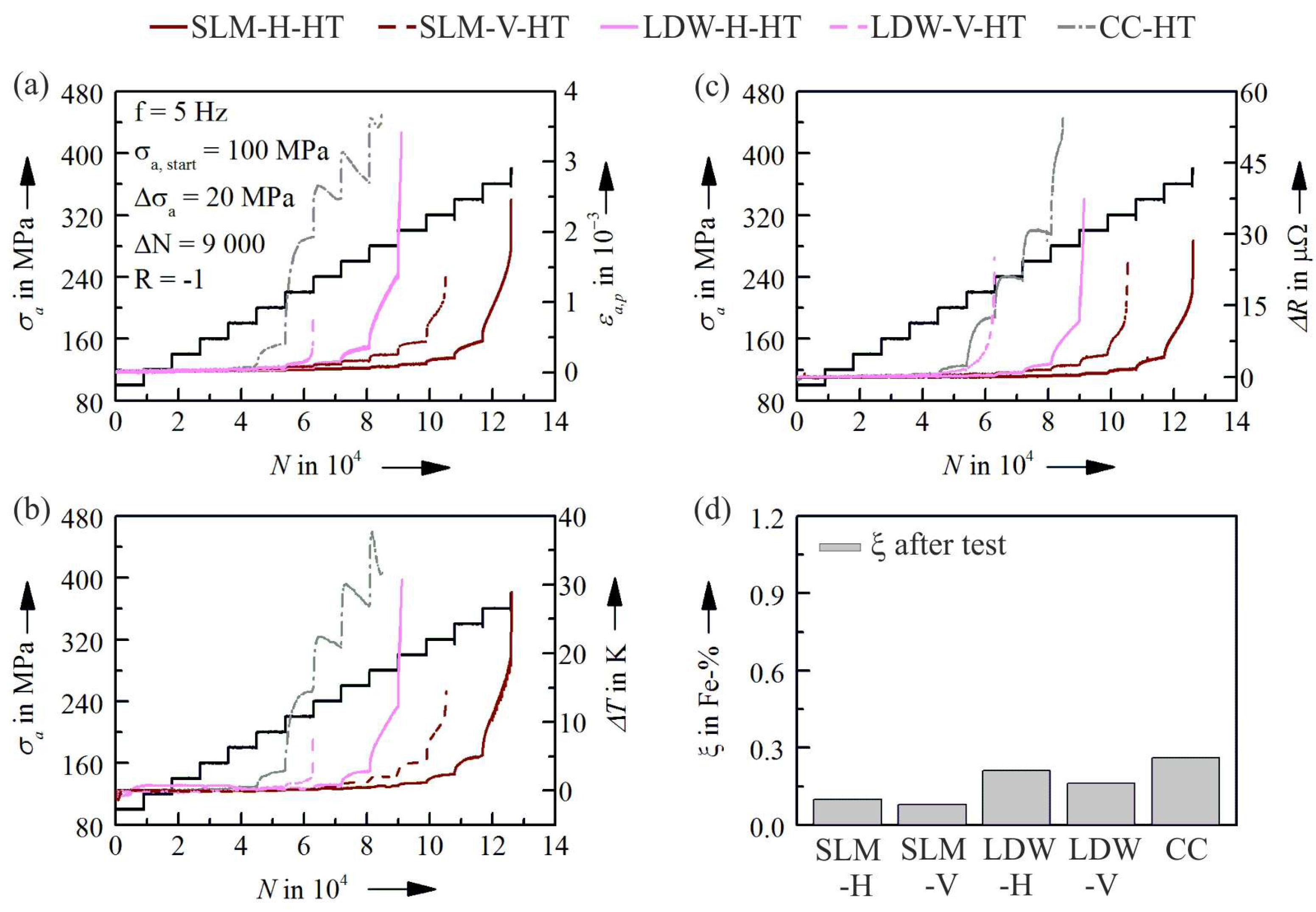
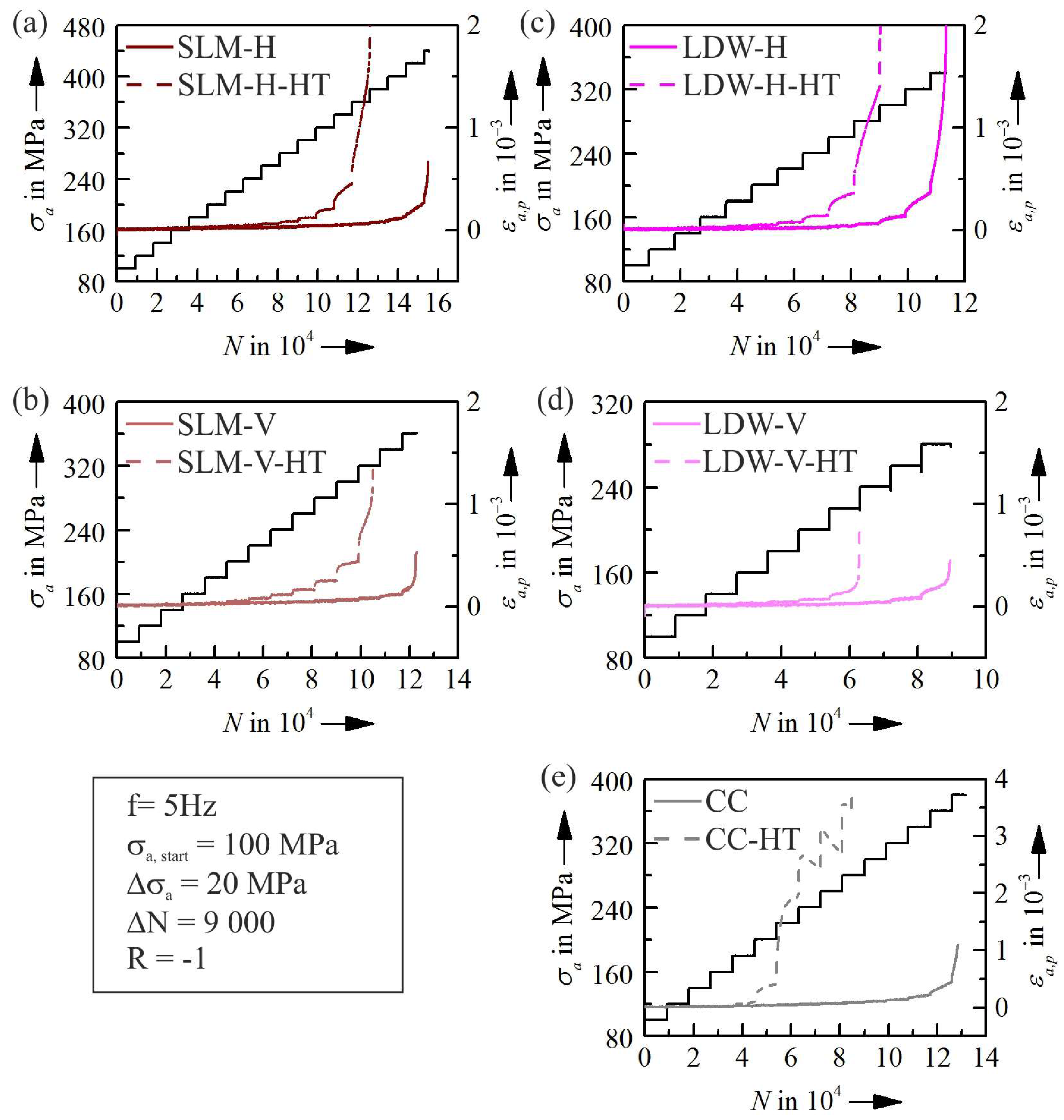
The LITs were performed on a servo-hydraulic fatigue testing system with a load ratio of 
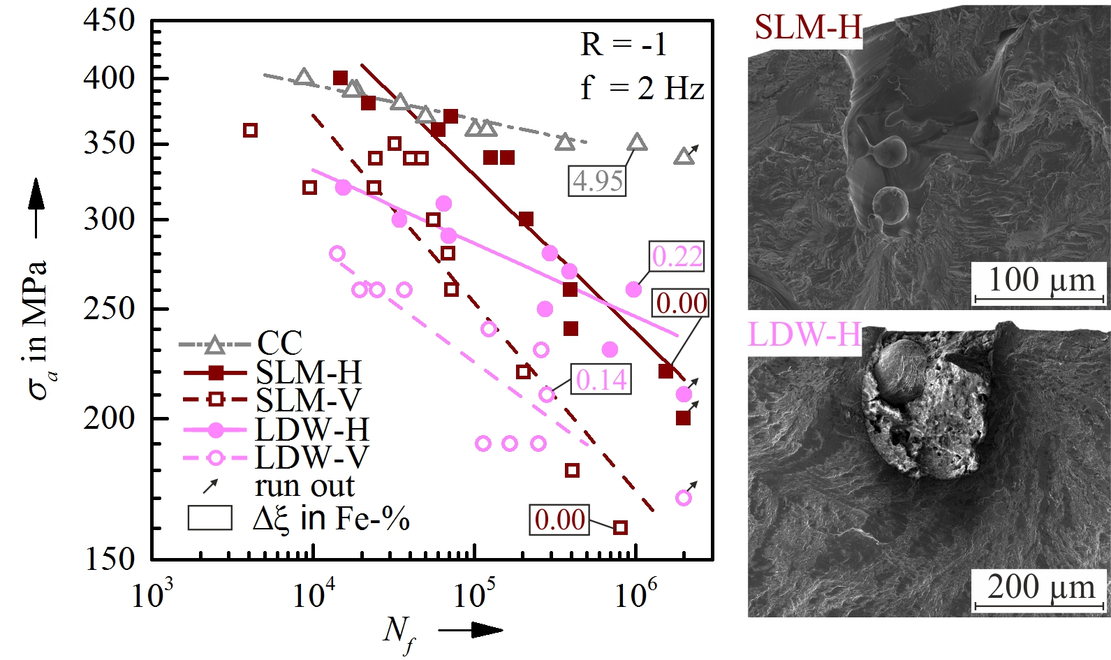
R = −1 and a frequency of 5 Hz in laboratory air at ambient temperature. For each type of specimen, two LITs were performed. The load amplitude of the first step was 100 MPa, the step length was 9000 cycles, and the load increase between each step was 20 MPa. To further investigate the fatigue behavior of the AM-microstructures, additional CATs were conducted at a frequency of 2 Hz and a stress ratio of 
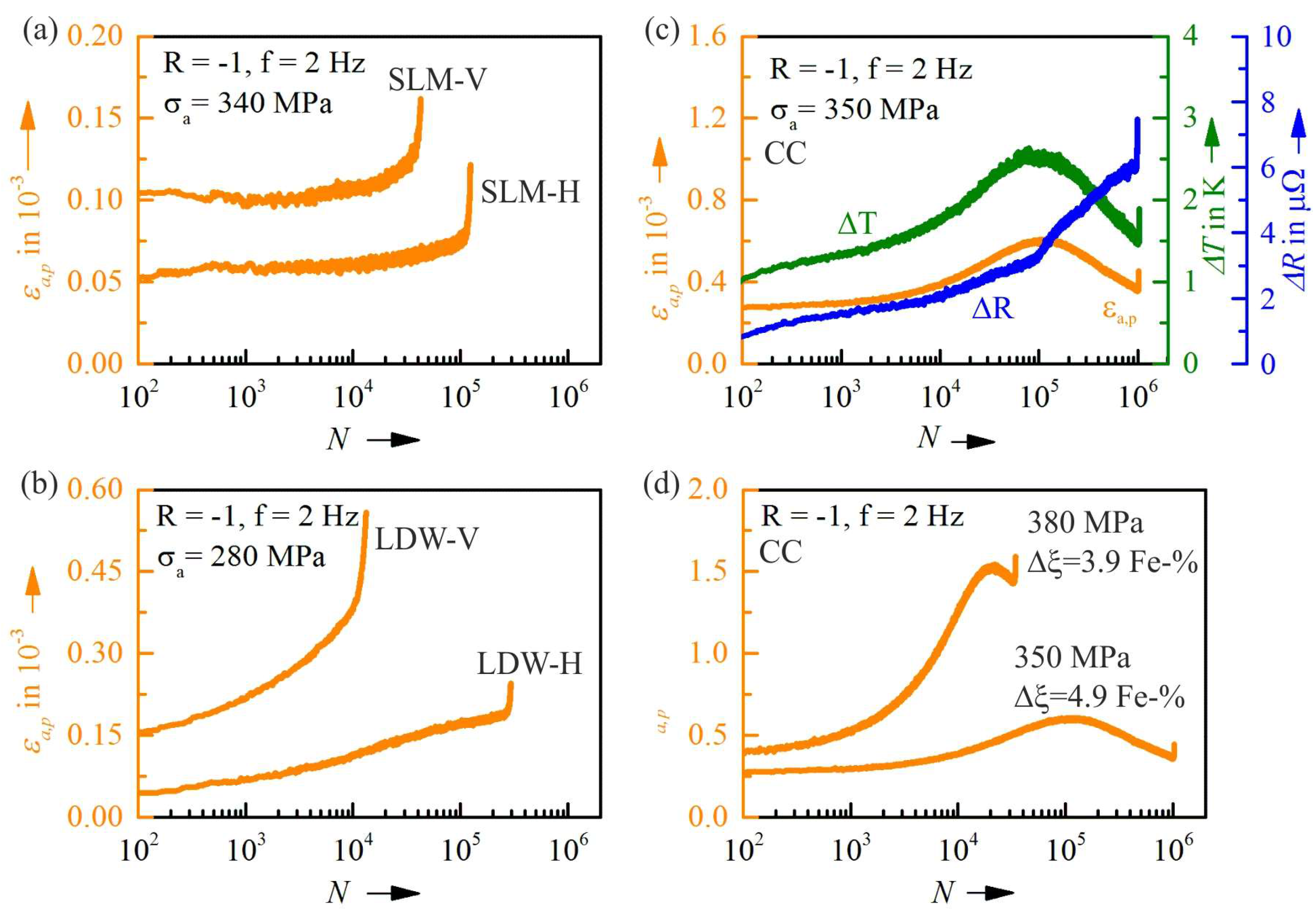
R = −1. The stress levels of the CATs were determined by means of the cyclic deformation behavior in the LITs. Based on the results in LITs, the frequency in CATs was reduced to avoid temperature increase under high constant amplitude loading. The plastic strain amplitude ε
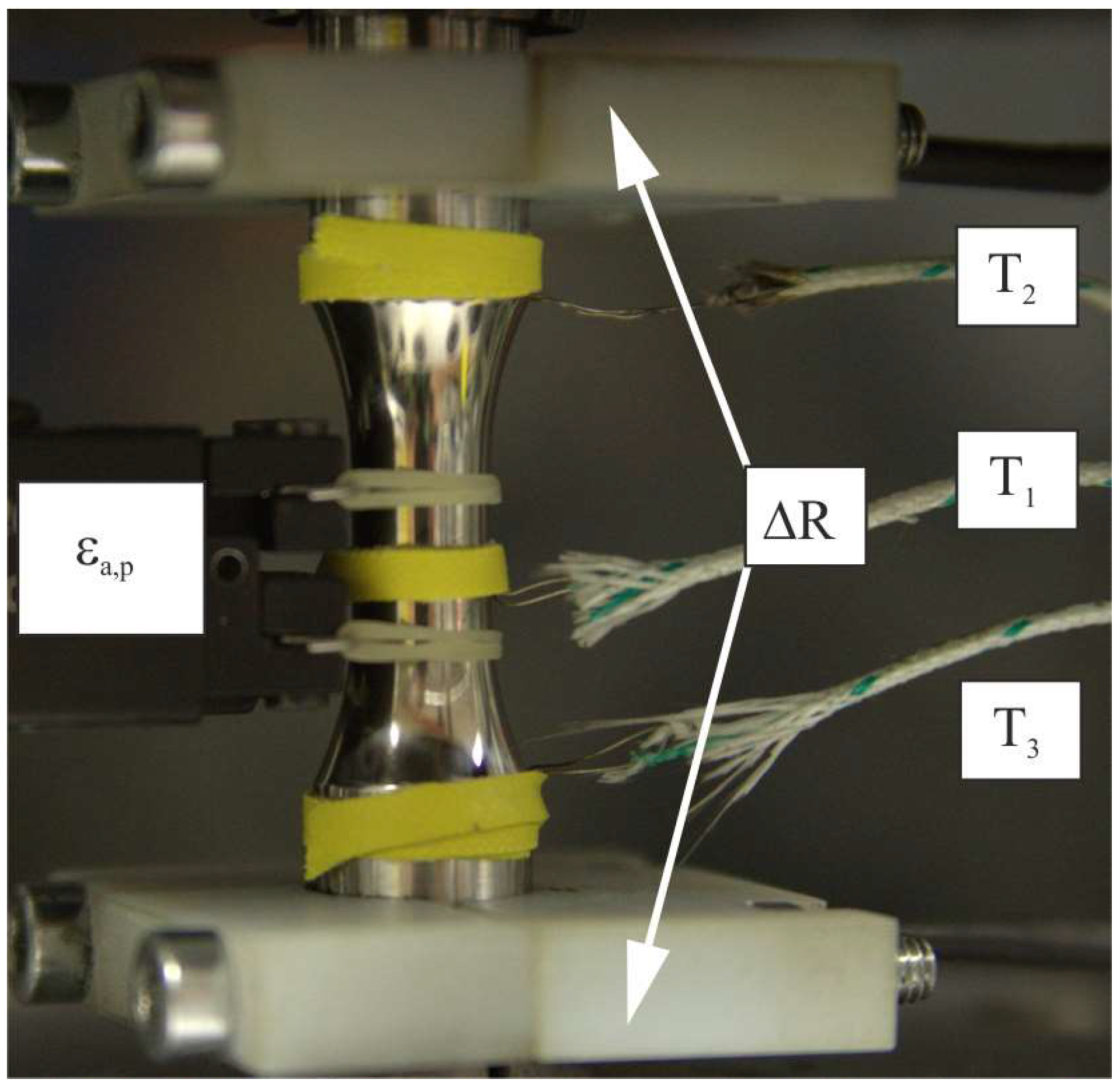
a,p was determined from the stress-strain-hysteresis loops measured by an extensometer. The area of each hysteresis loop describes the cyclic plastic strain energy dissipated per unit volume during a given loading cycle, which is mainly dissipated into heat and, hence, results in a change in the specimen temperature [34]. The temperature was measured with one thermocouple in the middle of the gauge length (T1) and two reference thermocouples at the elastically loaded specimen shafts (T2 and T3; see Figure 4). The temperature change induced by cyclic plastic deformation was calculated according to Equation (2) [34].
Δ T   =   T 1     T 2   +   T 3 2
Additionally, the change in the electrical resistance ΔR of the material during the fatigue tests was measured. The specific electrical resistance is influenced by microstructural defects—for example, pores, microcracks, vacancies, and dislocation structures, which makes this measurement sensitive to fatigue processes [34]. For ΔR measurements, a constant direct current of 8 A was applied to the specimen and the voltage drop was measured between the ends of the gauge length (see Figure 4).
The content of the ferromagnetic phase of the specimens was measured before and after tensile tests as well as fatigue tests using a FERITSCOPE™ MP 30E device (Helmut Fischer GmbH, Sindelfingen, Germany) to determine and quantify the transformation from paramagnetic austenite to ferromagnetic α′-martensite (Δξ) given in Fe-%. Measurements before the tests were conducted on the surface of the gauge length, while measurements after the tests were performed on both the surface of the gauge length and on the fracture surface.

4. Results and Discussion

4.1. Microstructure

Figure 5 shows the LOMs of cross-sections of differently manufactured and heat treated (HT) specimens. The AM-specimens showed a typical elongation of grains along the building direction, both in the as-built and heat treated condition, which could also be observed in the electron backscatter diffraction (EBSD) orientation maps (see Figure 5a,c,f,h and Figure 6a,c,e,g). This typical feature of AM-specimens, especially in the as-built condition, was already shown in other investigations of additively manufactured 316L [14,15,35] and can be explained by the directed heat flux during solidification, from the melt pool into the already applied material. In the cross-sections of the horizontally built specimens, the boundaries of the melt pools can be identified (see Figure 5a,c,f,h) according to the results of References [13,15,16,35]. In the heat treated SLM-H-specimens the visibility of the melt pool boundaries was much less pronounced than in the as-built condition (compare Figure 5a,f).
Grain sizes were rated in conformity to DIN EN ISO 643 [31] (see Table 3) on the cross-sections of the differently manufactured specimens. Due to the abovementioned grain elongation corresponding with a grain aspect ratio of <1, the grain size number of the AM-specimens was higher perpendicular to the building direction than along the building direction (see Table 3).
The grain sizes of the SLM-specimens (G = 6–7) were lower than that of the LDW-specimens (G = 1–3), due to the higher cooling rates correlating with smaller melt pool sizes in the SLM process. The CC-specimens (G = 5) showed a higher grain size than the SLM-specimens but a lower grain size than the LDW-specimens. Note that the ε-martensite and the twin boundaries were not taken into account in the grain size determination. Figure 5e shows that very thin, dark needles exist in a few austenitic grains, which indicate the presence of ε-martensite in the CC-specimens. The ε-martensite has a hexagonal crystallographic structure, is paramagnetic, and can be formed by plastic deformation. Furthermore, intersections of ε-martensite are nuclei for deformation induced α′-martensite [26,36]. The heat treatment did not influence the grain structure of the AM-specimens significantly (Figure 5 and Figure 6; Table 3), while CC-specimens showed an increased grain size and no ε-martensite was detected after the heat treatment.
Note that the LOMs of cross-sections of vertically/ horizontally built specimens correspond to the LOMs of longitudinal sections of horizontally/vertically built specimens (see Figure 7).
One of the main aspects in the microstructure of the AM-material is the occurrence of inhomogeneities like pores or oxide inclusions [15,20,37]. The porosity of the differently manufactured and heat treated materials was rated based on a minimum of ten LOMs for each type of specimen, which was taken from a minimum of five different samples, respectively. In addition to the results given in Reference [24], a larger number of specimens were investigated. The SLM-specimens exhibited a higher porosity than the LDW-specimens (Table 4). Because of the higher laser power [38] and the bigger layer thickness [39] in the LDW process, the porosity of the LDW-specimens was lower. Due to these differences in the process parameters, the penetration depth of the laser in LDW-process was higher, which led to a higher level of bonding compared to the SLM-specimens. Hence, the LDW-specimens exhibited a lower amount of incomplete bonding between melt pools, which is the main reason for the pores in the AM-materials (see Figure 8a).
The horizontally built SLM-specimens exhibited a higher porosity compared to the vertically built SLM-specimens. This could be caused by the slight differences in the parameters in the manufacturing process, which has, as can be seen in Figure 7, obviously no influence on the microstructure except on the porosity of the SLM-material. In Figure 7, the longitudinal sections (LS) and cross-sections (CS) of the SLM-specimens manufactured in the different building directions are shown. The microstructure of the different building directions exhibit no significant differences and also the heat treatment has no significant influence on the porosity of the AM-materials (see Table 4).
Oxide inclusions were observed in LDW-specimens (see Figure 8b and Figure 9). These inclusions showed a higher concentration of O, Si, and Mn, and a lower content of Fe, indicating the prevalence of SiMn-Oxides (see Figure 9). The oxide inclusions resulted from an incomplete coverage of the melt pool by the protective inert gas flow during the LDW-process [37] and were significantly more extended than the pores in the LDW-specimens (see Figure 8b). This leads to the assumption that the influence of oxide inclusions on the fatigue behavior is more pronounced.

4.2. Indentation and Tensile Tests

To investigate the mechanical properties of the differently manufactured and heat treated specimens, tensile tests, cyclic indentation tests, and macro- and microhardness measurements were conducted.
Note that for the AM-specimens, the indentations were placed in the cross-sections (see Figure 2) of the specimens with horizontal building direction parallel to the layer planes, while in vertically built specimens the indents were placed perpendicular to the layer planes. As can be seen from Figure 10, the microhardness distribution of the AM-specimens is not influenced by the building direction. In the as-built condition, the AM-specimens, both from the LDW and from SLM processing, showed a rather flat microhardness distribution. While the cooling rate and temperature gradient at the individual melt pools were very high, the distribution of the cooling rates along the cross section of the AM-specimens was nearly homogeneous due to the small volume fraction of each single melt pool, which led to the observed flat microhardness distributions. The CC-specimens showed an increased hardness in the near surface regions caused by the inhomogeneous plastic deformation during cold drawing, which led to the enhanced work hardening close to the surface. The SLM-specimens in the as-built condition showed a higher hardness than in the center of the CC- and in the overall cross section of the LDW-specimens (see Figure 10 and Table 5). The LDW-specimens showed the lowest hardness, which correlates to their relatively large grain sizes (see Figure 5 and Figure 6; Table 3 and Table 5).
The heat treatment led to a decreased and, in case of the CC-material flattened, microhardness distribution in all specimens. Compared to the LDW- and SLM-specimens, the CC-specimens exhibited the most pronounced decrease of hardness, indicating a reduction of the work hardening induced effects during the heat treatment. These assumptions correlate to the investigations of Altenberger et al. on austenitic steel AISI 304 [29] and are currently under further investigation. Furthermore, the ε-martensite detected in the initial state (Figure 5e) transforms completely to austenite (Figure 5j). Moreover, the ferromagnetic phase fraction, that is, the α′-martensite, is reduced by the heat treatment up to 0.0 Fe-% (compare Table 8 to Table 9), which also decreases the hardness of all specimen variants.
The results of the cyclic microindentation tests exhibited significant differences between the differently manufactured specimens in the as-built condition. The SLM-specimens showed lower ha,p-values than the LDW- and CC-specimens (see Figure 11). In the as-built condition, the hardening potential of the LDW-specimens was the highest and differed significantly to the eII-values of the SLM- and CC-specimens (see Figure 11 and Table 6).
The heat treatment significantly influences the results of the cyclic microindentation tests. In the first cycles, the ha,p-values of the heat treated specimens are similar to those in the as-built condition, while for N > 5, ha,p becomes significantly lower than in the as-built condition (see Figure 11). Hence, it can be concluded that the hardening potential of the heat treated specimens is higher, which can be seen by comparison of the values of eII in the as-built and heat treated conditions (see Table 6). The highest increase of the hardening potential due to the heat treatment was observed in the CC-specimens (Figure 11 and Table 6), which was caused by the reduction of the work hardening after the heat treatment.
Similar to the results of the microhardness measurements, no anisotropic behavior of the AM-specimens was observed in cyclic microindentation tests.
Tensile tests were conducted at the differently manufactured specimens in the as-built condition as published in Reference [24]. Young’s moduli of all specimens were in a similar range. However, as soon as the elastic range was exceeded, the AM-specimens showed an anisotropic behavior, that is, the horizontally built specimens showed a higher tensile strength, 0.2% yield stress, and elongation at the fracture (see Table 7). This anisotropic behavior is typical for AM-specimens; see for example, References [10,15,19,40,41].
The SLM-V-specimens showed similar tensile and 0.2% yield stress as the CC-specimens, while SLM-H-specimens showed even higher values. The tensile strength and the 0.2% yield stress of the LDW-H specimens were also close to the CC-specimens, while the LDW-V-specimens showed significantly lower values (see Table 7). The increase of the magnetic fraction (ξ in Fe-%) correlates with the austenite stabilities caused by the different chemical compositions (see Table 2). However, the different austenite stabilities influenced the elongation at the fracture. Accordingly, the CC-specimens showed the highest elongation at the fracture and the LDW-specimens showed the higher elongation at fracture than the SLM-specimens, for each building direction.

4.3. Fatigue Behavior of the Differently Manufactured Specimens

4.3.1. Fatigue Behavior in As-Built Condition

Load Increase Tests (LITs)

To rate the fatigue properties of the differently manufactured and heat treated specimens, cyclic deformation curves (εa,p-), ΔT-curves, and ΔR-N-curves obtained by LITs were analyzed. Besides the shape of the εa,p-, ΔT- and ΔR-N-curves, the load step at failure σf and the last load step—during which the linear growth of the measured material reaction occurs (indicated as σl) and after which a nonlinear increase of the εa,p, ΔT, and ΔR is indicated—are observed (see Figure 12). To compare the fatigue properties at lower stress amplitudes σl and at higher stress amplitudes σf can be used as the reference value.
As obvious from Figure 12 and Figure 13, the development of all measured materials reactions correlate well and result in identical stress amplitudes σ1.
In accordance with the anisotropic tensile properties, the horizontally built specimens in the as-built condition show a higher fatigue performance in the LIT (see Figure 13; Table 7 and Table 8).
The SLM-H-specimens exhibited the highest values of σf and σl. The SLM-V- and CC-specimens showed the same values of σl and the SLM-V-specimens had a slightly lower σf value than the CC-material. The LDW-H specimens exhibited lower values of σf but a delayed increase in the material’s reactions compared to the CC- and SLM-V-specimens, while the LDW-V-specimens showed lowest values of both σf and σl.

Constant Amplitude Tests and S-Nf-Curves

To further investigate the fatigue behavior of the differently manufactured specimens, CATs were conducted. To get sufficiently reliable information for the comparison of the fatigue behavior of the differently manufactured specimens, for each specimen type, a minimum number of ten CATs were performed in the HCF-regime. As seen in Figure 14, the anisotropic behavior of the AM-materials also occurs in CATs, that is, the vertically built specimens from both Additive Manufacturing processes exhibited a decreased fatigue strength, a slightly steeper slope in the S-Nf-curve, and also a higher scatter compared to the horizontal building direction, although the SLM-H-specimens (1.54 area %) showed a higher porosity than the SLM-V-specimens (0.85 area %) (see Table 4).
The cyclic deformation behavior of the differently manufactured specimens reflects the differences in austenite stabilities. The SLM- and LDW-specimens showed cyclic softening during the whole duration of the CATs, while the CC-specimens exhibited cyclic hardening, after a shorter phase of cyclic softening at the beginning of the CATs, due to a larger extent of α′-martensite formation (see Figure 15). Besides the decreased plastic strain amplitude, this resulted in an increased change in the electrical resistance as seen in Figure 15c. The relatively small amount of austenite-α′-martensite-transformation in the LDW-specimens does not lead to the global cyclic hardening and seems to be a locally restricted process in the microstructure in the LDW-material (see Figure 14 and Figure 15b).
Furthermore, the anisotropic cyclic deformation behavior of the AM-specimens from both SLM and LDW are characterized by the higher plastic strain amplitudes and lower lifetimes of the vertically built variants (see Figure 15a,b).
In each building direction, the SLM-specimens showed an increased fatigue life at higher stress amplitudes and a decreased fatigue life at lower stress amplitudes compared to the LDW-specimens. This correlates with the austenite-α′-martensite-transformation in the LDW-specimens indicated by an increase in the ferromagnetic fraction (Δξ) of about 0.1–0.2 Fe-%. In the SLM-specimens, no increase of magnetic fraction during the CATs was observed (see Figure 14). Obviously, this leads to an increase in the fatigue life of the LDW-specimens, especially at lower stress amplitudes, due to the reduction of the stress concentrations at oxide inclusions by the austenite-α′-martensite-transformation, leading to local compressive residual stresses according to the results of References [42,43]. The CC-specimens showed—similar to LDW-specimens—a lower fatigue life than the SLM-H-specimens at high-stress amplitudes, while at lower stress amplitudes, the CC-specimens reach a higher number of cycles to failure. This is caused by a more extended cyclic hardening at lower stress amplitudes of CC-specimens (see Figure 15d) caused by the austenite-α′-martensite-transformation, resulting in a flatter S-Nf-curve. These results show that the austenite stability has a significant influence on the fatigue behavior of the differently manufactured 316L-specimens.
Fractography of differently manufactured specimens after fatigue failure showed crack initiation in the AM-specimens at microstructural defects, that is, oxide inclusions or pores. The CC-specimens showed crack initiation from slip bands at the surface. As expected, crack initiation in the SLM-specimens occurred for both building directions at the pores in the near surface area (less than 1 mm distance to the surface of the gauge length) (see Figure 16a). For the LDW-specimens in both building directions, cracks were initiated at the oxide inclusions in the near surface area (see Figure 16b). Therefore, pores can be considered as the main crack initiating defects under cyclic loading for SLM- and oxide inclusions for LDW-specimens. Pores are hence, the main reason for the scatter in the determined S-Nf-curves (see Figure 14).
By comparison of the different S-Nf-curves, the AM-specimens showed a significantly lower fatigue strength compared to the CC-specimens, which is mainly caused by the occurrence of defects in the AM-material and work hardening in the CC-specimens, but also because of the influence by the different austenite stabilities resulting from the individual chemical compositions. Hence, the influence of the austenite stability has to be taken into account when comparing the fatigue behavior of differently manufactured 316L.
By comparison of the results of the LITs and CATs, it can be seen that the influence of the austenite-α′-martensite-transformation, which is prevalent especially at lower stress amplitudes, cannot be detected with LITs. However, if the material shows the same austenite stability, the anisotropy in the fatigue behavior can be described with low experimental effort by LITs in good accordance with CATs. Hence, LITs can be used to efficiently determine the influence of the process parameter variation or the post-treatment on the anisotropic fatigue behavior.

4.3.2. Fatigue Behavior in the Heat Treated Condition

Because LITs provide an efficient means to describe the anisotropic fatigue behavior of AM-specimens, this method was applied for the investigation of the heat treatment influence on the fatigue properties of the investigated material variants.
In Figure 17, the representative results of LITs at two different SLM-H-HT-specimens are shown. Both the changes in the electrical resistance ΔR and the plastic strain amplitude εa,p show nearly the same development up to the last three loading steps, resulting in identical values of σl and σf, indicating the repeatability of the results of LITs.
In the heat treated condition, as in as-built condition, the AM-specimens show an anisotropic fatigue behavior (see Figure 18 and Table 9). Because, in both conditions, the microstructure shows an elongation of grains and the boundaries of the melt pools from the Additive Manufacturing process are retained after heat treatment, it can be concluded that the grain structure and layer arrangement cause the typical anisotropic fatigue behavior of AM-specimens.
In the heat treated condition, all specimens showed decreased fatigue performance and higher plastic deformation compared to the as-built condition (see Figure 19 and compare Table 8 and Table 9), which may be caused by a lower amount of α′-martensite, indicated by a smaller content of the ferromagnetic phase of 0.0 Fe-% after annealing at 1070 °C/2 h/H2O (compare Table 8 and Table 9). The CC-HT-specimens especially showed a significant decrease in the fatigue performance and lower values of σf and σl, which was caused by the decrease of both the work hardening and the content of ε-martensite (see Section 4.2). For each building direction, the SLM-HT-specimens exhibited, similar to the as-built condition, a higher fatigue performance than the LDW-HT-specimens. The location of the crack initiation of the heat treated specimens is similar to the as-built condition at the surface near defects, that is, pores (SLM) and oxide inclusions (LDW).
The temperature increase during the LITs was more pronounced in the horizontally built specimens than in the vertically built specimens, which is associated with the higher amount of plastic strain amplitude occurring at the last load steps of LITs in the horizontally built specimens. For LDW-H-HT and SLM-H-HT, the specimen temperature exceeded 50 °C in the last two load steps and for CC-HT-specimens in the last three load steps, respectively. This temperature increase could be avoided with a lower test frequency. In the present work, a uniform test frequency of 5 Hz was chosen for the LITs to ensure the comparability of the as-built condition. Furthermore, the active cooling of the specimens during the fatigue tests was not conducted in order to ensure the comparability of the plastic deformation induced change in the temperature ΔT between the LITs of the as-built and heat treated specimens.
The magnetic fraction before the LIT is zero for all types of specimens in the heat treated condition due to the complete re-transformation of the ferromagnetic phase into austenite during the heat treatment (see Table 9). Taking the higher plastic strain amplitudes of the heat treated specimens into account, it could be expected that the content of the ferromagnetic phase of those specimens to be higher after the LIT. However, in case of the heat-treated LDW- and CC-specimens, the content of the ferromagnetic phase after the LIT was lower than in the as-built condition. This can be explained by the larger increase in temperature and lower stress amplitudes during the LIT compared to the as-built condition. Furthermore, the lower content of ε-martensite in the CC-HT-specimens leads to a lower number of nuclei for the deformation induced α′-martensite transformation.
The CC-HT-specimens showed pronounced cyclic hardening during the different load steps in the LIT and a lower increase of the content of magnetic fraction compared to the as-received condition. Hence, the cyclic hardening of CC-HT-specimens seems not to be dominated by the austenite-α′-martensite-transformation and the cyclic hardening of the austenitic phase must determine the cyclic deformation behavior. Note that the scale of the plastic strain amplitude εa,p in Figure 19e is two times larger compared to the graphs representing the results of AM-specimens. In all the load steps with plastic strain amplitudes significantly above 2 × 10⁻³, the CC-HT-material showed cyclic hardening. All the AM-specimen variants and the as-received CC-specimens exhibited significantly lower plastic strain amplitudes and therefore, no cyclic hardening in LITs. These details of cyclic deformation behavior are currently under further investigation.

5. Summary and Conclusions

Additively manufactured (AM-) austenitic stainless steel AISI 316L blanks, produced by Selective Laser Melting (SLM) (process category: powder bed fusion [12]) and Laser Deposition Welding (LDW) (process category: direct energy deposition [12]), were investigated with regard to their microstructure and mechanical properties. The results were compared to Continuous Casted, hot and cold drawn (CC) 316L blanks. The blanks were turned into final specimen geometry. For fatigue investigations, the fatigue specimens were additionally mechanically polished in the gauge length in order to exclude the influence of surface topography resulting from the different manufacturing processes and to focus the investigations on the volume microstructure. The AM-blanks were manufactured in the horizontal building direction in which the layer planes are parallel to the load axis of the specimens (SLM-H, LDW-H) and in the vertical building direction (SLM-V, LDW-V) in which the layer planes are perpendicular to the load axis of the specimens. Additionally, the differently manufactured specimens were heat treated (HT) and their results were compared to those of the as-built condition.
The differently manufactured specimens exhibited differences in chemical composition and, hence, in austenite stability, leading to the highest austenite stability in the CC-materials and the lowest in the SLM-material.
The heat treatment (2 h, 1070 °C, H2O) did not influence the grain structure of the AM-specimens significantly, while the heat-treated CC-specimens showed increased grain size than in the as-built condition.
Microhardness measurements of the specimens in the as-built condition showed a rather flat microhardness distribution of the SLM- and LDW-specimens, while the CC-specimens showed an increased hardness in the near surface regions. The heat-treated specimens generally showed a decreased hardness compared to the as-built condition.
The results of the cyclic microindentation tests showed differences in the hardening potential of the differently manufactured specimens, while the building direction had no influence. The heat treatment led to an increased hardening potential for all specimens, with a major influence on the CC-specimens.
Fatigue investigations were conducted with load increase tests (LITs). The AM-specimens showed in the as-built condition an anisotropic fatigue behavior with regard to the building direction in correlation to tensile tests. The SLM-H specimens showed highest values for the load step of failure σf and the last load step before the first significant material reaction σl. Similar to tensile tests, the LDW-H-specimens and SLM-V-specimens showed, in the as-built condition, a competitive fatigue performance in LIT compared to CC-specimen, while the LDW-V-specimens showed significantly lower values of σf and σl.
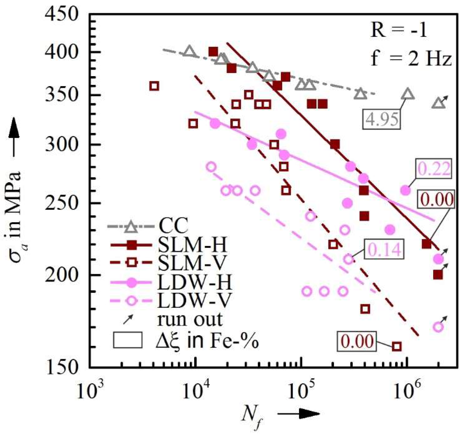
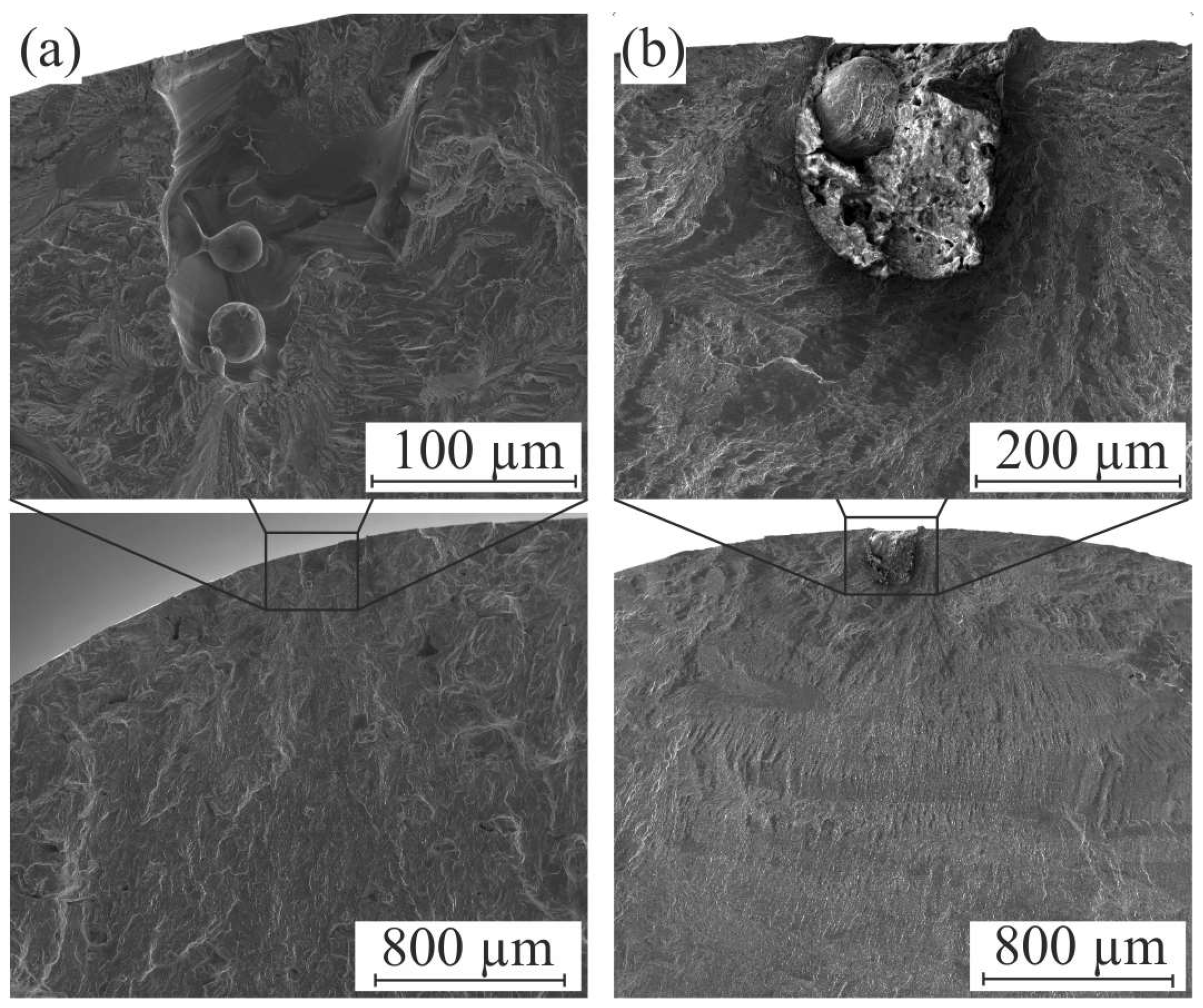
In constant amplitude tests (CATs), the AM-specimens showed a decreased fatigue strength compared to the CC-specimens, which was mainly caused by defects in the AM-materials, that is, pores (SLM) and oxide inclusions (LDW). Therefore, these defects have to be avoided as far as possible in additive manufacturing of cyclically loaded components. It can also be seen that the austenite stability has a big influence on the fatigue behavior of the differently manufactured specimens and hence, has to be taken into account in the rating of the fatigue properties of additively and conventionally manufactured 316L. Furthermore, the CATs showed an anisotropic fatigue behavior of the AM-specimens with regard to the building direction: horizontally built specimens showed a higher fatigue strength, lower scatter, and flatter slope in S-Nf-curves.
The results showed that LITs can characterize the anisotropic fatigue behavior of AM-materials with only one fatigue test for each building direction in an efficient way. LITs could be used to investigate the influence of different post-treatments or variation of manufacturing parameters on the anisotropic fatigue behavior of AM-materials. In the present study, LITs were used to show that an additional heat treatment (2 h, 1070 °C, H2O) leads to significantly lower fatigue performance of all specimen variants, but did not influence the anisotropic fatigue behavior of AM-specimens.
Based on the results of microstructural investigations, it is concluded that the anisotropic behavior is based on the elongation of grains and the arrangement of boundaries of the melt pools, which are both influenced by the building direction.
The main conclusions of the present work are that for determination of fatigue behavior, the austenite stability of the additively manufactured 316L has to be taken into account and that the load increase test can characterize the anisotropic fatigue behavior of AM-materials efficiently. This method was used for rating the fatigue behavior of the heat treated specimens.
In further investigations, the influence of defects, chemical composition, and building direction on additively manufactured 316L, with a stronger focus on the process parameters in the additive manufacturing process will be investigated by means of the short-time procedures LIT, PhyBaLCHT, and PhyBaLLIT [33].

Acknowledgments

The research described in this paper was funded by European Union’s European Regional Development Fund (ERDF) and the Commercial Vehicle Cluster (CVC) Südwest.

Author Contributions

Bastian Blinn, Marcus Klein and Tilmann Beck planned the experimental design, interpreted the given results and wrote the majority of the present paper; Marek Smaga was substantially involved in interpretation of the influence of austenite stability; Christopher Gläßner and Jan C. Aurich did aquire the investigated material, wrote the majority of the introduction of the paper, and were substantially involved in the discussion of the given results.

Conflicts of Interest

The authors declare no conflicts of interest.

References

  1. VDI-Standard: VDI 3405. Additive Manufacturing Processes, Rapid Manufacturing—Basics, Definitions, Processes; Beuth Verlag: Berlin, Germany, 2014. [Google Scholar]
  2. Levy, G.N.; Schindel, R.; Kruth, J.P. Rapid manufacturing and rapid tooling with layer manufacturing (LM) technologies, state of the art and future. Ann. CIRP 2003, 52, 589–609. [Google Scholar] [CrossRef]
  3. Santorinaios, M.; Brooks, W.; Sutcliffe, C.J.; Mines, R.A.W. Crush behaviour of open cellular lattice structures manufactured using selective laser melting. High Perform. Struct. Mater. III 2006, 85, 481–490. [Google Scholar] [CrossRef]
  4. Brennea, F.; Niendorf, T.; Maier, H.J. Additively manufactured cellular structures: Impact of microstructure and local strains on the monotonic and cyclic behavior under uniaxial and bending load. J. Mater. Process. Technol. 2013, 213, 1558–1564. [Google Scholar] [CrossRef]
  5. Buchbinder, D.; Schleifenbaum, H.; Heidrich, S.; Meiners, W.; Bültmann, J. High Power Selective Laser Melting (HP SLM) of Aluminum Parts. Phys. Procedia 2011, 12, 271–278. [Google Scholar] [CrossRef]
  6. Schmidt, M.; Merklein, M.; Bourell, D.; Dimitrov, D.; Hausotte, T.; Wegener, K.; Overmeyer, L.; Vollertsen, F.; Levy, G.N. Laser based additive manufacturing in industry and academia. CIRP Ann. Manuf. Technol. 2017, 66, 561–581. [Google Scholar] [CrossRef]
  7. Morrow, W.R.; Qi, H.; Kim, I.; Mazumder, J.; Skerlos, S.J. Environmental aspects of laser-based and conventional tool and die manufacturing. J. Clean. Prod. 2007, 15, 932–943. [Google Scholar] [CrossRef]
  8. Buchanan, C.; Matilainen, V.-P.; Salminen, A.; Gardner, L. Structural performance of additive manufactured metallic material and cross-sections. J. Constr. Steel Res. 2017, 136, 35–48. [Google Scholar] [CrossRef]
  9. Daniewicz, S.R.; Shamsaei, N. An introduction to the fatigue and fracture behavior of additive manufactured parts. Int. J. Fatigue 2017, 94, 167. [Google Scholar] [CrossRef]
  10. Lewandowski, J.J.; Seifi, M. Metal Additive Manufacturing: A Review of Mechanical Properties. Annu. Rev. Mater. Res. 2016, 46, 151–186. [Google Scholar] [CrossRef]
  11. Shamsaeia, N.; Yadollahi, A.; Bian, L.; Thompson, S.M. An overview of Direct Laser Deposition for additive manufacturing; Part II: Mechanical behavior, process parameter optimization and control. Addit. Manuf. 2015, 8, 12–35. [Google Scholar] [CrossRef]
  12. ISO/ASTM 52900:2015. Additive Manufacturing—General Principles—Terminology; BSI Standards Limited: Geneva, Switzerland, 2015. [Google Scholar]
  13. Mower, T.M.; Long, M.J. Mechanical behavior of additive manufactured, powder-bed laser-fused materials. Mater. Sci. Eng. A 2016, 651, 198–213. [Google Scholar] [CrossRef]
  14. Yasa, E.; Kruth, J.-P. Microstructural investigation of Selective Laser Melting 316L stainless steel parts exposed to laser re-melting. Procedia Eng. 2011, 19, 389–395. [Google Scholar] [CrossRef]
  15. Casati, R.; Lemke, J.; Vedani, M. Microstructure and Fracture Behavior of 316L Austenitic Stainless Steel Produced by Selective Laser Melting. J. Mater. Sci. Technol. 2016, 32, 738–744. [Google Scholar] [CrossRef]
  16. Brandl, E.; Schoberth, A.; Leyens, C. Morphology, microstructure, and hardness of titanium (Ti-6Al-4V) blocks deposited by wire-feed additive layer manufacturing (ALM). Mater. Sci. Eng. A 2012, 532, 295–307. [Google Scholar] [CrossRef]
  17. Caiazzo, F.; Alfieri, V.; Corrado, G.; Argenio, P. Laser powder-bed fusion of Inconel 718 to manufacture turbine blades. Int. J. Adv. Manuf. Technol. 2017, 93, 4023–4031. [Google Scholar] [CrossRef]
  18. Bauer, T.; Dawson, K.; Spierings, A.B.; Wegener, K. Microstructure and mechanical characterisation of SLM processed Haynes® 230®. In Proceedings of the 26th Annual International Solid Freeform Fabrication (SFF) Symposium, Austin, TX, USA, 10–12 August 2015. [Google Scholar]
  19. Yadollahi, A.; Shamsaei, N.; Thompson, S.M.; Elwany, A.; Bian, L. Effects of building orientation and heat treatment on fatigue behavior of selective laser melted 17-4 PH stainless steel. Int. J. Fatigue 2017, 94, 218–235. [Google Scholar] [CrossRef]
  20. Günther, J.; Krewerth, D.; Lippmann, T.; Leuders, S.; Tröster, T.; Weidner, A.; Biermann, H.; Niendorf, T. Fatigue life of additively manufactured Ti-6Al-4V in the very high cycle fatigue regime. Int. J. Fatigue 2017, 94, 236–245. [Google Scholar] [CrossRef]
  21. Leuders, S.; Thöne, M.; Riemer, A.; Niendorf, T.; Tröster, T.; Richard, H.A.; Maier, H.J. On the mechanical behaviour of titanium alloy TiAl6V4 manufactured by selective laser melting: Fatigue resistance and crack growth performance. Int. J. Fatigue 2013, 48, 300–307. [Google Scholar] [CrossRef]
  22. Greitemeier, D.; Palm, F.; Syassen, F.; Melz, T. Fatigue performance of additive manufactured TiAl6V4 using electron and laser beam melting. Int. J. Fatigue 2017, 94, 211–217. [Google Scholar] [CrossRef]
  23. Stoffregen, H.A.; Butterweck, K.; Abele, E. Fatigue Analysis in Selective Laser Melting: Review and Investigation of Thin-walled Actuator Housings. In Proceedings of the 25th Annual International Solid Freeform Fabrication Symposium—An Additive Manufacturing Conference, Austin, TX, USA, 4–6 August 2014; pp. 635–650. [Google Scholar]
  24. Gläßner, C.; Blinn, B.; Burkhart, M.; Klein, M.; Beck, T.; Aurich, J.C. Comparison of 316L test specimens manufactured by Selective Laser Melting, Laser Deposition Welding and Continuous Casting. In 7. WGP-Jahreskongress; Schmitt, R.H., Schuh, G., Eds.; Apprimus: Aachen, Germany, 2017; pp. 45–52. ISBN 978-3-86359-555-5. [Google Scholar]
  25. Leuk Lai, J.K.; Lo, K.H.; Shek, C.H. Stainless Steels: An Introduction and Their Recent Developments; Bentham Science Publishers: Hong Kong, China, 2012; ISBN 978-1-60805-305-6. [Google Scholar]
  26. Hahnenberger, F.; Smaga, M.; Eifler, D. Microstructural investigation of the fatigue behavior and phase transformation in metastable austenitic steels at ambient and lower temperatures. Int. J. Fatigue 2014, 69, 36–48. [Google Scholar] [CrossRef]
  27. Smaga, M.; Walther, F.; Eifler, D. Deformation-Induced Martensitic Transformation in Metastable Austenitic Steels. Mater. Sci. Eng. A 2008, 483–484, 394–397. [Google Scholar] [CrossRef]
  28. Angel, T. Formation of martensite in austenitic stainless steel—Effects of deformation, temperature and composition. J. Iron Steel Inst. 1954, 177, 165–174. [Google Scholar]
  29. Altenberger, I.; Scholtes, B.; Martin, U.; Oettel, H. Cyclic deformation and near surface microstructures of shot peened or deep rolled austenitic stainless steel AISI 304. Mater. Sci. Eng. A 1999, 264, 1–16. [Google Scholar] [CrossRef]
  30. Man, J.; Kubena, I.; Smaga, M.; Man, O.; Jaevenpaa, A.; Weidner, A.; Chlup, Z.; Polak, J. Microstructural changes during deformation of AISI 300 grade austenitic stainless steels: Impact of chemical heterogeneity. Procedia Struct. Integr. 2016, 2, 2299–2306. [Google Scholar] [CrossRef]
  31. DIN EN ISO. 643: Steels—Micrographic Determination of the Apparent Grain Size (ISO 643:2012); German Version EN ISO 643:2012; ISO: Geneva, Switzerland, 2012. [Google Scholar]
  32. ASTM. A 240/A 240Ma: Standard Specification for Chromium and Chromium-Nickel Stainless Steel Plate, Sheet, and Strip for Pressure Vessels and for General Applications; ASTM: West Conshohocken, PA, USA, 2016. [Google Scholar]
  33. Kramer, H.S.; Starke, P.; Klein, M.; Eifler, D. Cyclic hardness test PHYBALCHT—Short-time procedure to evaluate fatigue properties of metallic materials. Int. J. Fatigue 2014, 63, 78–84. [Google Scholar] [CrossRef]
  34. Biallas, G.; Piotrowski, A.; Eifler, D. Cyclic stress-strain, stress-temperature and stress-electrical resistance response of NiCuMo allyed sintered steel. Fatigue Fract. Eng. Mater. Struct. 1995, 18, 605–615. [Google Scholar] [CrossRef]
  35. Yadollahi, A.; Shamsaei, N.; Thompson, S.M.; Seely, D.W. Effects of process time interval and heat treatment on the mechanical and microstructural properties of direct laser deposited 316L stainless steel. Mater. Sci. Eng. A 2015, 644, 171–183. [Google Scholar] [CrossRef]
  36. Venables, J.A. The martensite transformation in stainless steel. Philos. Mag. J. Theor. Exp. Appl. Phys. 1962, 7, 35–44. [Google Scholar] [CrossRef]
  37. Ganesh, P.; Kaul, R.; Sasikala, G.; Kumar, H.; Venugopal, S.; Tiwari, P.; Rai, S.; Prasad, R.C.; Kukreja, L.M. Fatigue Crack Propagation and Fracture Toughness of Laser Rapid Manufactured Structures of AISI 316L Stainless Steel. Metallogr. Microstruct. Anal. 2014, 3, 36–45. [Google Scholar] [CrossRef]
  38. Kamath, C.; El-dasher, B.; Gallegos, G.F.; King, W.E.; Sisto, A. Density of additively-manufactured, 316L SS parts using laser powder-bed fusion at powers up to 400 W. Int. J. Adv. Manuf. Technol. 2014, 74, 65–78. [Google Scholar] [CrossRef]
  39. Spierings, A.B.; Levy, G. Comparison of density of stainless steel 316L parts produced with selective laser melting using different powder grades. In Proceedings of the SFF Symposium, Austin, TX, USA, 3–5 August 2009. [Google Scholar]
  40. Yu, J.; Rombouts, M.; Maes, G. Cracking behavior and mechanical properties of austenitic stainless steel parts produced by laser metal deposition. Mater. Des. 2013, 45, 228–235. [Google Scholar] [CrossRef]
  41. Suryawanshi, J.; Prashanth, K.G.; Ramamurty, U. Mechanical behavior of selective laser melted 316L stainless steel. Mater. Sci. Eng. A 2017, 696, 113–121. [Google Scholar] [CrossRef]
  42. Grigorescu, A.C.; Hilgendorff, P.-M.; Zimmermann, M.; Fritzen, C.-P.; Christ, H.-J. Effect of geometry and distribution of inclusions on the VHCF properties of a metastable austenitic stainless steel. Adv. Mater. Res. 2014, 891–892, 440–445. [Google Scholar] [CrossRef]
  43. Grigorescu, A.C.; Hilgendorff, P.-M.; Zimmermann, M.; Fritzen, C.-P.; Christ, H.-J. Cyclic deformation behavior of austenitic Cr–Ni-steels in the VHCF regime: Part I—Experimental study. Int. J. Fatigue 2016, 93, 250–260. [Google Scholar] [CrossRef]
Figure 1. The geometry of the fatigue specimens.
Metals 08 00220 g001
Figure 2. The schematic description of the microhardness measurements.
Metals 08 00220 g002
Figure 3. PhyBaLCHT: the schematic description of (a) the indentation force-indentation depth-hysteresis loop and (b) the ha,p-N-curves described by two power laws according to Reference [33].
Metals 08 00220 g003
Figure 4. The experimental setup for fatigue tests.
Metals 08 00220 g004
Figure 5. Light Optical Micrographs (LOMs) of 316L cross-sections for (a) SLM-H [24], (b) SLM-V [24], (c) LDW-H, (d) LDW-V, (e) CC [24], (f) SLM-H-HT, (g) SLM-V-HT, (h) LDW-H-HT, (i) LDW-V-HT, and (j) CC-HT.
Metals 08 00220 g005
Figure 6. The electron backscatter diffraction (EBSD) orientation maps of the cross-sections for (a) SLM-H [24]; (b) SLM-V [24]; (c) LDW-H [24]; (d) LDW-V [24]; (e) SLM-H-HT; (f) SLM-V-HT; (g) LDW-H-HT, and (h) LDW-V-HT.
Metals 08 00220 g006
Figure 7. The LOMs of (a) the longitudinal section (LS) of the SLM-H-specimen, (b) the cross section (CS) of the SLM-H-specimen, (c) the CS of the SLM-V-specimen, and (d) the LS of the SLM-V-specimen.
Metals 08 00220 g007
Figure 8. (a) Pore at the layer boundary of an SLM-H-specimen and (b) [24] the oxide inclusion and pore in a LDW-H-specimen.
Metals 08 00220 g008
Figure 9. SiMn oxide inclusions in a LDW-V-specimen [24].
Metals 08 00220 g009
Figure 10. The microhardness distribution in the cross-sections of (a) SLM-H, (c) SLM-V, (b) LDW-H, (d) LDW-V, and (e) continuous casted (CC) in the as-built condition [24] and the heat treated condition.
Metals 08 00220 g010
Figure 11. The plastic indentation depth amplitude (ha,p)-N-curves of (a) SLM-H, (c) SLM-V, (b) LDW-H, (d) LDW-V, and (e) CC in the as-built condition [24] and the heat treated condition.
Metals 08 00220 g011
Figure 12. The determination of the load step of the first significant reaction of the material based on the measurements of the plastic strain amplitude (εa,p), the change in temperature (ΔT), and the change in electrical resistance (ΔR) for a load increase test (LIT) of a SLM-H-specimen in the as-built condition.
Metals 08 00220 g012
Figure 13. The measurements of (a) plastic strain amplitude (εa,p), (b) change in temperature (ΔT), (c) change in electrical resistance (ΔR), and (d) magnetic fraction (ξ) on the surface of the gauge length in LITs of differently manufactured specimens in the as-built condition.
Metals 08 00220 g013
Figure 14. The S-Nf-curves of the differently manufactured specimens with Δξ-measurements in the gauge length before and after the constant amplitude tests (CATs) on a lower stress level.
Metals 08 00220 g014
Figure 15. The cyclic deformation behavior of (a) SLM-specimens in CATs, (b) LDW-specimens in CATs, and of CC-specimens in (c) LIT and (d) CATs with measurements of plastic strain amplitude εa,p (in (ad)), plastic deformation induced change in temperature ΔT (in (a)) and change in electrical resistance ΔR (in (a)).
Metals 08 00220 g015
Figure 16. The fracture surfaces in the region of the crack initiation due to pores at (a) SLM-H-specimen (σa = 300 MPa; Nf = 212,218) and due to inclusions at (b) LDW-H-specimen (σa = 260 MPa; Nf = 982,098).
Metals 08 00220 g016
Figure 17. Measurements of the plastic strain amplitude (εa,p) and the change in electrical resistance (ΔR) during two different SLM-H-HT specimens.
Metals 08 00220 g017
Figure 18. The measurements of (a) plastic strain amplitude (εa,p), (b) change in temperature (ΔT), (c) change in electrical resistance (ΔR) in LITs of differently manufactured specimens in the heat treated condition and (d) Fe-Signal (ξ) in the gauge length after specimen failure.
Metals 08 00220 g018
Figure 19. The measurements of the plastic strain amplitude (εa,p) in LITs of differently manufactured specimens with regard to the influence of heat treatment on the fatigue performance of (a) SLM-H-, (b) SLM-V, (c) LDW-H-, (d) LDW-V-, and (e) CC-specimens.
Metals 08 00220 g019
Table 1. The manufacturing parameters of the Additive Manufacturing (AM)-blanks [24].
Additive Manufacturing TechnologySLMLDW
Manufacturing machineEOS M 290DMG MORI LASERTEC 65 3D
Powder size in µm25–4550–150
Av. Layer thickness in µm40400
Dimension as-built in mmØ14 × 10215 × 15 × 103
Building direction Metals 08 00220 i001horizontal (SLM-H) Metals 08 00220 i002vertical (SLM-V) Metals 08 00220 i003horizontal (LDW-H) Metals 08 00220 i004vertical (LDW-V)
Table 2. The chemical compositions and Md30,Angel-temperatures of the investigated AISI austenitic stainless steel 316L (1.4404) batches [24].
Amount of Alloying Element in wt. %CNSiMnCrNiMoFeMd30,Angel in °C
SLM0.020.080.611.4417.6813.072.2664.68−58.3
LDW0.030.100.531.3016.4110.542.0468.75−28.5
CC0.020.030.381.6516.5910.482.0368.189.1
ASTM A 182min----16.0010.002.0060.8061.8
max0.030.101.002.0018.0015.003.0072.00−117.1
Table 3. The grain sizes of the differently manufactured and heat treated specimens.
SpecimenSLM-HSLM-VLDW-HLDW-VCC
Grain size number G67135
SpecimenSLM-H-HTSLM-V-HTLDW-H-HTLDW-V-HTCC-HT
Grain size number G67134
Table 4. Porosities of the differently manufactured and heat treated specimens.
SpecimenSLM-HSLM-VLDW-HLDW-VCC
Porosity in area %1.54 ± 0.490.85 ± 0.270.03 ± 0.010.02 ± 0.010
SpecimenSLM-H-HTSLM-V-HTLDW-H-HTLDW-V-HTCC-HT
Porosity in area %1.26 ± 0.190.93 ± 0.380.02 ± 0.010.03 ± 0.010
Table 5. The macrohardness measurements of the differently manufactured and heat treated specimens.
SpecimenSLM-HSLM-VLDW-HLDW-VCC
HV30/10219215171177202
SpecimenSLM-H-HTSLM-V-HTLDW-H-HTLDW-V-HTCC-HT
HV30/10175179159154131
Table 6. The cyclic hardening exponentsCHT eII of the differently manufactured and heat treated specimens.
SpecimenSLM-HSLM-VLDW-HLDW-VCC
|eII|0.391 ± 0.0250.399 ± 0.0160.456 ± 0.0250.455 ± 0.0090.396 ± 0.020
SpecimenSLM-H-HTSLM-V-HTLDW-H-HTLDW-V-HTCC-HT
|eII|0.491 ± 0.0210.467 ± 0.0130.540 ± 0.0220.540 ± 0.0160.568 ± 0.021
Table 7. The mechanical properties in the tensile tests of differently manufactured specimens in the as-built condition [24].
SpecimenSLM-HSLM-VLDW-HLDW-VCC
Rm in MPa681 ± 7612 ± 2629 ± 7564 ± 9639 ± 2
Rp0.2 in MPa609 ± 43490 ± 2438 ± 40322 ± 2454 ± 4
Young’s modulus in GPa167 ± 12152 ± 7172 ± 12170 ± 10161 ± 6
A in %28.9 ± 3.921.4 ± 1.637.8 ± 0.326.8 ± 4.944.5 ± 1.5
ξbefore TT in Fe-%0.13 ± 0.010.11 ± 0.020.68 ± 0.010.68 ± 0.090.17 ± 0.01
ξafter TT in Fe-%Surface gauge length0.13 ± 0.010.15 ± 0.011.13 ± 0.131.05 ± 0.262.90 ± 0.10
Fracture surface0.13 ± 0.020.15 ± 0.011.80 ± 0.702.30 ± 0.908.55 ± 0.15
Table 8. The load step of failure (σf), last load step of linear growth of measurements (σl), and the development of ξ on the fracture surface and gauge length after LIT in the as-built condition.
SpecimenSLM-HSLM-VLDW-HLDW-VCC
σf in MPa440360340280380
σl in MPa300240260220240
ξbefore LIT in Fe-%0.15 ± 0.010.15 ± 0.020.48 ± 0.100.53 ± 0.100.17 ± 0.00
ξafter LIT in Fe-%Surface gauge length0.15 ± 0.010.17 ± 0.010.99 ± 0.220.69 ± 0.090.86 ± 0.08
Fracture surface0.190.191.601.502.10
Table 9. The load step of failure (σf), last load step of linear growth of measurements (σl), and development of ξ on the fracture surface and gauge length after load increase (LIT) in the heat treated condition.
SpecimenSLM-H-HTSLM-V-HTLDW-H-HTLDW-V-HTCC-HT
σf in MPa380320300220280
σl in MPa240200180140160
ξbefore LIT in Fe-%0.000.000.000.000.00
ξafter LIT in Fe-%Surface gauge length0.10 ± 0.060.08 ± 0.060.21 ± 0.060.16 ± 0.020.29 ± 0.02
Fracture surface0.130.150.360.641.40

