Abstract
This study characterizes the microstructure and its associated crystallographic features of bulk maraging steels fabricated by selective laser melting (SLM) combined with a powder bed technique. The fabricated sample exhibited characteristic melt pools in which the regions had locally melted and rapidly solidified. A major part of these melt pools corresponded with the ferrite (α) matrix, which exhibited a lath martensite structure with a high density of dislocations. A number of fine retained austenite (γ) with a <001> orientation along the build direction was often localized around the melt pool boundaries. The orientation relationship of these fine γ grains with respect to the adjacent α grains in the martensite structure was (111)γ//(011)α and [-101]γ//[-1-11]α (Kurdjumov–Sachs orientation relationship). Using the obtained results, we inferred the microstructure development of maraging steels during the SLM process. The results depict that new and diverse high-strength materials can be used to develop industrial molds and dies.
1. Introduction
Metal additive manufacturing based on three-dimensional computer-aided design (CAD) models is a promising technology for fabricating metal products with arbitrary complex geometries within short time-frames [1,2,3,4]. A popular additive manufacturing process for metals is powder bed fusion (PBF) [2] in which the powder particles of metals (alloys) are melted and fused using either laser or electron beams. PBF technologies include the commonly used selective laser melting (SLM), selective laser sintering, selective heat sintering, and electron beam melting [3,4]. The SLM process has been recently applied to various steel powders [3,4], yielding geometrically complex components of maraging steels [5]. Maraging steels with high strength and adequate toughness [6] are extensively applied as tool steels in the mold and die-making industries. When applied to maraging steels, SLM could enable efficient manufacturing of an extensive variety of high-performance molds and dies for pressing or forging complex-shaped metal products.
The maraging steel would be favorable for the SLM process in terms of microstructure development. The local heating by laser-beam irradiation produces melt pools, which is followed by rapid solidification at an extremely high cooling rate [7,8]. During the cooling process, the locally irradiated areas are rapidly quenched from the austenitic region to reach temperatures that are lower than the martensite start temperature, resulting in the formation of a martensite structure that contributes strengthening materials. The strength level of SLM-fabricated maraging steels is approximately 1 GPa [9,10,11]. The subsequent aging at elevated temperatures (~460 °C) enhances the precipitation of fine intermetallic phases within the martensite structure, which further strengthens the materials [9,10,11]. However, most previous studies have investigated the effect of laser scanning conditions and aging treatments on the mechanical properties (strength and fatigue) of SLM-fabricated maraging steels [11,12,13,14]. Although the crystallographic orientation relation has been determined in as-quenched maraging steels [15], the microscopic features of the SLM-generated martensite structure remain unclear.
The current study characterizes the microstructural and crystallographic features of the martensite structure in the SLM-fabricated maraging steel using electron microscopy and electron backscatter diffraction (EBSD). Based on the results, the current study further discusses the development of microstructure in maraging steel during the SLM process.
2. Experimental Procedure
Table 1 presents the nominal and measured compositions of the maraging steel powder (depicted in Figure 1) and fabricated bulk sample, analyzed by inductively coupled plasma-atomic emission spectrometry (ICP–AES). A SEM image of the studied powder is shown in Figure 1. The proportions of major alloy elements were observed to be almost identical in both the initial powder and the SLM-fabricated bulk samples. The SLM processing was conducted at room temperature using a 3D systems ProX 200 (3D SYSTEMS, Rock Hill, SC, USA) additive-manufacturing system equipped with a Yb-fiber laser operating at 255 W (Figure 2a). The hexagonal grid laser-scanning pattern that has been applied in this study is depicted in Figure 2b. The fabrication parameters were as follows: laser spot size = approximately 100 μm, applied scan speed = 2.083 m/s, bedded-powder layer thickness = 30 µm, hatch spacing between adjacent laser-scanning tracks = 50 μm, and rotation angle between the bedded-powder layers = 90°. The optimization of the laser scanning parameters will be described in the following papers. The oxidation during the SLM process was prevented using high-purity Ar gas. Hereafter, the directions that are normal and parallel to the bedded-powder layer are designated as the Z and X/Y directions, respectively. To perform optical microscopy and scanning electron microscopy (SEM), the built bulk samples were cut out from the base plate and then mechanically polished, followed by etching with a natal solution at room temperature. The microstructures were observed using an SEM operating at 20 kV. The orientation was analyzed by EBSD with a 0.3 µm step size. The thin foil sample for transmission electron microscopy (TEM) was ion-polished by an ion-slicer (JEOL, Akishima, Japan) at 6.0 V. The TEM observation was performed using a JEM-2100 plus (JEOL, Akishima, Japan) operating at 200 kV.

Table 1.
Nominal and measured compositions of the investigated powdered and bulk maraging steels (wt. %), analyzed using inductively coupled plasma-atomic emission spectroscopy.
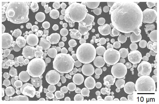
Figure 1.
Scanning electron microscope (SEM) image of the powder particles studied.
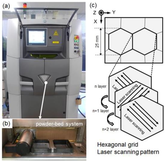
Figure 2.
(a) Appearance of the used selective laser melting (SLM) machine (3Dsystems ProX 200) and (b) inside a chamber for powder-bed system; (c) schematic of the laser-scanning tracks on each powder layer applied in this study.
3. Results
Figure 3 depicts the microstructures of the SLM-fabricated maraging steel at various magnifications. The characteristic microstructure of the SLM-fabricated sample (Figure 3a,b) comprises semi-cylindrical melt pools corresponding to the locally melted and rapidly solidified regions that are exposed to scanning laser irradiations [16,17,18]. The melt pools were approximately 50–100 µm high (Figure 3a) and approximately 50 µm wide (Figure 3b). They contained elongated cellar structures with a mean spacing of approximately 500 nm (Figure 3c,d), as reported in the literature [10,11,19,20,21]. The elongation direction of the cellar structure appears to be independent of the presence of the melt pool boundaries. Fine grains with relatively granular morphologies were locally observed at the boundaries between the melt pools (indicated by arrows in Figure 3d). These morphologies differ from the cellar morphologies observed inside the melt pools. Figure 4 presents a TEM bright filed image showing the dislocation substructure in the SLM-fabricated maraging steel. The TEM observation reveals a lath structure with a high density of dislocations. The mean lath width is approximately 200 nm. The electron diffraction pattern obtained from the observed area indicates the diffused orientation inside the lath structure. These features correspond well to previous studies on microstructural characterization of as-quenched maraging steels [15]. At the resolution level of conventional TEM, no precipitates larger than 10 nm were observed inside the lath structure, which is consistent with a previous result of atomic-probe tomography [19,20,21].
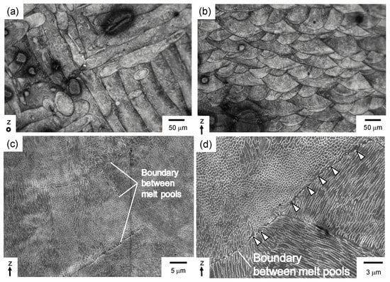
Figure 3.
(a,b) optical micrographs; (c,d) SEM image showing microstructure of the maraging steel fabricated by selective laser melting of power bed metal, which were observed from (a) z direction and (b–d) normal to z direction.
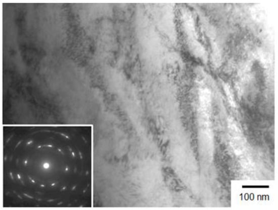
Figure 4.
Transmission electron microscope (TEM) bright-filed image showing dislocation substructures in the maraging steel fabricated by selective laser melting of power bed metal, which were observed from a normal to z direction.
Figure 5 presents the EBSD result of the SLM-fabricated sample. The EBSD analysis of the melt-pool microstructure revealed that a number of fine austenite (γ) grains were distributed in a ferrite (α) matrix (Figure 5a,b). The retained γ phases often appeared along the grain boundaries in the α-Fe matrix. This result strongly agrees with the results of previous studies [9,10,21]. Notably, the fine γ grains were often localized at the melt pool boundaries. The microstructural morphologies observed in the α phase (Figure 5c) corresponded well with the lath martensite structure characterized by EBSD analyses [15,22], indicating that a martensite structure developed in the SLM-fabricated maraging steels. Many of the fine γ grains were oriented at <001> along the Z direction (Figure 5d), forming a {001} texture of the retained γ phase (Figure 5e). Note that no particular crystallographic textures were observed in the α phase (Figure 5c).
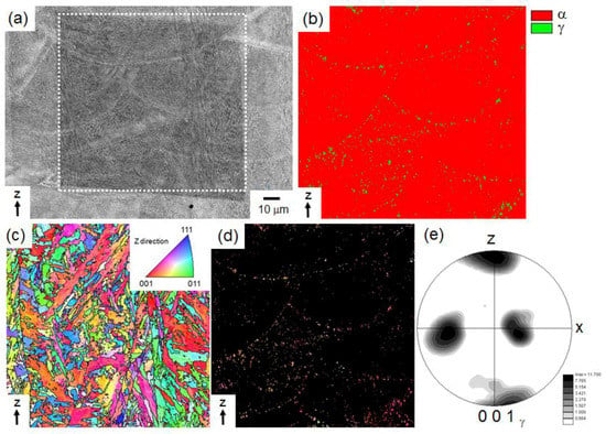
Figure 5.
(a) SEM image depicting the microstructure of the SLM-fabricated maraging steel; (b) its corresponding phase map for α(bcc) and γ (fcc) phases; (c) orientation color map of the α phase; (d) orientation color map of the γ phase; and (e) stereographic projection of the 001 poles in the γ phase presented in Figure 5d.
Figure 6a,b presents the EBSD color maps of the α and γ phases. The corresponding stereographic projections depicting the low-index orientations obtained by performing the EBSD analyses are displayed in panels c–f. EBSD analysis revealed the orientation relationship between the fine retained γ grains oriented at <001> along the Z direction (Figure 6b) and the adjacent α grains in the martensite structure (Figure 6a). As exhibited in the obtained stereographic projections (Figure 6c,d), the fine γ grain has an orientation relation of (111)γ//(011)α and [-101]γ//[-1-11]α with respect to the adjacent α grain (indicated by αA in Figure 6a). The stereographic projections (Figure 6e,f) represent the fine γ grain also has a different variant of (111)γ//(011)α and [-101]γ//[-1-11]α with respect to another adjacent α grain (indicated by αB in Figure 6a). The determined orientation relationship corresponds to the Kurdjumov–Sachs (K–S) orientation relationship between lath martensite and austenite [22] and is consistent with the crystallographic features of the lath martensite structure in conventionally quenched maraging steels [15].
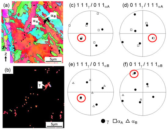
Figure 6.
High-magnification orientation color maps in the (a) α and (b) γ phases; (c–f) stereographic projections of the (c,e) 111γ /011α and (d,f) 011γ /111α poles. The orientation of the γ phase was extracted from the γ grains depicted in (b). The αA and αB grains adjacent to the γ grain are indicated in (a).
4. Discussion
In general, the characteristic microstructures of SLM-fabricated metals and alloys develop through local melting and rapid solidification during SLM [7,8]. To assess the phase transition in the maraging steel sample in solidification (during SLM process), the Fe-Ni-Co-Mo-Ti system was predicted via thermodynamic equilibrium calculations performed based on the CALPHAD approach [23] using an existing thermodynamic database for Fe-based multi-component systems (PanIron) [24]. Figure 7 shows the composition of the studied maraging steel in a vertical section representing Fe–18Ni–9Co–5Mo–1Ti (wt. %) of the Fe–Ni–Co–Mo–Ti system. The ICP–AES analyzed composition (Table 1) was used for the alloy composition. In the studied composition, the initial solid phase is γ (fcc) below 1440 °C, whereas a γ single-phase region forms below the solidus temperature of approximately 1400 °C, and has a wide temperature range from 800 °C to 1400 °C. Below 800 °C, µ-Fe7Mo6 phase appears and then α (bcc) phase form at lower temperature than 650 °C. The thermodynamic calculation assesses γ phase initially forms in liquid (L) phase. The assessment indicates the γ grains solidifying in the direction of the hottest point of the melt pool, considering the <001> preferential solidification direction of the fcc solid phase [25] as well as other fcc metals (Ni [26,27] or Al alloys [16,17,18]). This result is consistent with the observed retained γ grains oriented at <001> along the Z direction (Figure 5). Although the calculated phase diagram predicts the formation of inter-metallics phases (µ-Fe7Mo6 [28] and η-Ni3Ti [29]) at lower temperature than 800 °C (Figure 7), the martensite transformation could occur inside the initially solidified γ phase because of sluggish kinetics for the formation of α phase in the maraging steels [30] in the subsequent cooling (after the solidification).
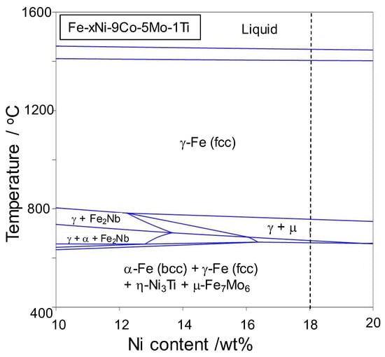
Figure 7.
A composition of maraging steel studied on a vertical section of Fe–9Co–5Mo–1Ti (wt. %) in a Fe–Ni–Co–Mo–Ti phase diagram calculated utilizing the reported thermodynamic database [24].
Based on the aforementioned experimental and calculated results, we can infer the development process of the microstructure in maraging steels during the SLM process. Figure 8 is a schematic of this development process. The laser-beam irradiation locally heats up and melts the bedded alloy powder layer, forming the melt pools. The primary solid phase (γ phase in the studied composition as indicated in Figure 7) is observed to form at the interface between the solid and liquid phases and grows to the center of the melt pool (the hottest point under the laser irradiation) in solidification (Figure 8a), as reported in the literature [16,17]. The γ grains solidify along the preferential <001> solidification direction, as reported in other fcc metals (Ni [26,27] or Al alloys [16,17,18]) that have been fabricated using the SLM process. The preferential solidification direction can explain the observed {001} texture of the retained γ phase (Figure 8e). During the rapid cooling process, the melt pool can rapidly solidify to a number of {001} oriented γ grains (Figure 8b). At temperatures that were lower than the initial martensite temperature (approximately 200 °C in the studied composition [30]), the solidified melt pool transformed into martensite (α phase) with a K–S orientation relation (determined in Figure 6), resulting in the development of the lath martensite structure (Figure 8c). The higher cooling rate around the liquid-solid interfaces in the irradiated regions would enhance the formation of the retained γ phase at the melt pool boundaries rather than inside the melt pools.
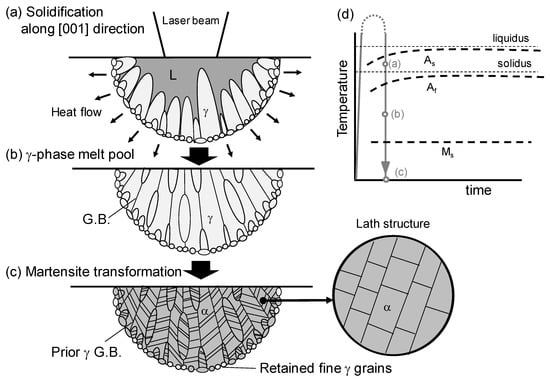
Figure 8.
Schematics showing (a–c) the formation process of microstructure in the maraging steel during the selective laser melting process, together with (d) a schematic thermal history of the sample by local laser heating.
The present study revealed a number of fine retained γ phases in the maraging steels fabricated by SLM, which are renowned to improve the ductility of steels with the martensite structure. The tensile ductility of SLM-fabricated alloys (Al, Ni, and Co alloys [31]) depends on the building direction, which is responsible for preferential fracturing along the melt pool boundaries [16,17,32]. However, in the SLM-fabricated maraging steel, the tensile ductility is apparently independent of direction [33] because the retained γ phase that is localized at the melt pool boundaries could suppress the preferential fracture along the melt pool boundaries. Consequently, controlling the retained γ phase inside the lath martensite structure could improve the mechanical performance of SLM-fabricated maraging steel. The proposed mechanism of microstructure development provides new insights about microstructure control by subsequent heat treatments. Furthermore, it has been interestingly reported that introducing carbides in the alloy powder enhances the formation of γ phase during the SLM process [34]. To control the microstructure (in particular the distribution of γ phase) by laser-scanning strategies during the SLM process and subsequent heat-treatments, it must await our future works to fundamentally investigate the austenite reversion of the SLM-fabricated maraging steel at elevated temperatures.
5. Summary
In this study, we have characterized microstructure and its associated crystallographic features of bulk maraging steels fabricated by selective laser melting (SLM) combined with a powder bed technique. The fabricated sample exhibited characteristic melt pools in which the regions had locally melted and rapidly solidified. A major part of these melt pools corresponded with the α- matrix, which exhibited a lath martensite structure with a high density of dislocations. A number of fine retained γ phase with a <001> orientation along the build direction was often localized around the melt pool boundaries. The orientation relationship of these fine γ grains with respect to the adjacent α grains in the martensite structure was determined as (111)γ//(011)α and [-101]γ//[-1-11]α (Kurdjumov–Sachs orientation relationship). Utilizing the obtained results, we inferred the microstructure development of maraging steels during the SLM process. These results can provide new insights to control microstructure of SLM-fabricated maraging steels by SLM process and subsequent heat treatments for developing materials for industrial molds and dies.
Author Contributions
N. Takata and R. Nishida performed microstructural characterizations and crystallographic analyses. R. Nishida, A. Suzuki and M. Kato fabricated the bulk sample by SLM process. N. Takata wrote and edited the paper. The research project was supervised by N. Takata and M. Kobashi.
Acknowledgments
The support of “Knowledge Hub Aichi,” which is a Priority Research Project of the Aichi Prefectural Government, Japan, is gratefully acknowledged. We are grateful for the technical support to prepare samples provided by Dr. Y. Ishida.
Conflicts of Interest
The authors declare no conflict of interest.
References
- Murr, L.E.; Gaytan, S.M.; Ramirez, D.A.; Martinez, E.; Hernandez, J.; Amato, K.N.; Shindo, P.W.; Medina, F.R.; Wicker, R.B. Metal Fabrication by Additive Manufacturing Using Laser and Electron Beam Melting Technologies. J. Mater. Sci. Technol. 2012, 28, 1–14. [Google Scholar] [CrossRef]
- King, W.E.; Anderson, A.T.; Ferencz, R.M.; Hodge, N.E.; Kamath, C.; Khairallah, S.A.; Rubenchi, A.M. Laser powder bed fusion additive manufacturing of metals; physics, computational, and materials challenges. App. Phys. Rev. 2015, 2, 041304. [Google Scholar] [CrossRef]
- Sames, W.J.; List, F.A.; Pannala, S.; Dehoff, R.R.; Babu, S.S. The metallurgy and processing science of metal additive manufacturing. Int. Mater. Rev. 2016, 61, 1–46. [Google Scholar] [CrossRef]
- Herzog, D.; Seyda, V.; Wycisk, E.; Emmelmann, C. Additive manufacturing of metals. Acta Mater. 2016, 117, 371–392. [Google Scholar] [CrossRef]
- Beyer, C.; Figueroa, D. Design and Analysis of Lattice Structures for Additive Manufacturing. ASME J. Manuf. Sci. Eng. 2016, 138, 121014. [Google Scholar] [CrossRef]
- ASM International. ASM Handbook Volume 2: Properties and Selection: Nonferrous Alloys and Special Purpose Materials; ASM International: Materials Park, OH, USA, 1990. [Google Scholar]
- Tang, M.; Pistorius, P.C.; Narra, S.; Beuth, J.L. Rapid Solidification: Selective Laser Melting of AlSi10Mg. JOM 2016, 68, 960–966. [Google Scholar] [CrossRef]
- Ding, X.; Wang, L. Heat transfer and fluid flow of molten pool during selective laser melting of AlSi10Mg powder: Simulation and experiment. J. Manuf. Proc. 2017, 26, 280–289. [Google Scholar] [CrossRef]
- Kempen, K.; Yasa, E.; Thijs, L.; Kruth, J.P.; Humbeeck, J.V. Microstructure and mechanical properties of Selective Laser Melted 18Ni-300 steel. Phys. Procedia 2011, 12, 255–263. [Google Scholar] [CrossRef]
- Casati, R.; Lemke, J.N.; Tuissi, A.; Vedani, M. Aging Behaviour and Mechanical Performance of 18-Ni 300 Steel Processed by Selective Laser Melting. Metals 2016, 6, 218. [Google Scholar] [CrossRef]
- Tan, C.; Zhou, K.; Ma, W.; Zhang, P.; Liu, M.; Kuang, T. Microstructural evolution, nanoprecipitation behavior and mechanical properties of selective laser melted high-performance grade 300 maraging steel. Mater. Des. 2017, 134, 23–34. [Google Scholar] [CrossRef]
- Meneghetti, G.; Rigon, D.; Cozzi, D.; Waldhauser, W.; Dabalà, M. Influence of building orientation on static and axial fatigue properties of maraging steel specimens produced by additive manufacturing. Struct. Integr. Procedia 2016, 7, 149–157. [Google Scholar] [CrossRef]
- Branco, R.; Costa, J.D.M.; Berto, F.; Razavi, S.M.J.; Ferreira, J.A.M.; Capela, C.; Santos, L.; Antunes, F. Low-Cycle Fatigue Behaviour of AISI 18Ni300 Maraging Steel Produced by Selective Laser Melting. Metals 2018, 8, 32. [Google Scholar] [CrossRef]
- Tian, J.; Huang, Z.; Qi, W.; Li, Y.; Liu, J.; Hu, G. Dependence of Microstructure, Relative Density and Hardness of 18Ni-300 Maraging Steel Fabricated by Selective Laser Melting on the Energy Density. In CMC2017: Advances in Materials Processing; Springer: Singapore, 2018; pp. 229–241. [Google Scholar]
- Morito, S.; Huang, X.; Furuhara, T.; Maki, T.; Hansen, N. The morphology and crystallography of lath martensite in alloy steels. Acta Mater. 2006, 54, 5323–5331. [Google Scholar] [CrossRef]
- Takata, N.; Kodaira, H.; Sekizawa, K.; Suzuki, A.; Kobashi, M. Microstructure and mechanical properties of AlSi10Mg alloy fabricated by selective laser melting. J. Jpn. Inst. Light Met. 2017, 67, 182–188. [Google Scholar] [CrossRef]
- Takata, N.; Kodaira, H.; Sekizawa, K.; Suzuki, A.; Kobashi, M. Change in microstructure of selectively laser melted AlSi10Mg alloy with heat treatments. Mater. Sci. Eng. A 2017, 704, 218–228. [Google Scholar] [CrossRef]
- Takata, N.; Kodaira, H.; Suzuki, A.; Kobashi, M. Size dependence of microstructure of AlSi10Mg alloy fabricated by selective laser melting. Mater. Charact. 2017. [Google Scholar] [CrossRef]
- Jägle, E.A.; Choi, P.-P.; Humbeeck, J.V.; Raabe, D. Precipitation and austenite reversion behavior of a maraging steel produced by selective laser melting. J. Mater. Res. 2014, 29, 2072–2079. [Google Scholar] [CrossRef]
- Kürnsteiner, P.; Wilms, M.B.; Weisheit, A.; Barriobero-Vila, P.; Jägle, E.A.; Raabe, D. Massive nanoprecipitation in an Fe-19Ni-xAl maraging steel triggered by the intrinsic heat treatment during laser metal deposition. Acta Mater. 2017, 129, 52–60. [Google Scholar] [CrossRef]
- Jägle, E.A.; Sheng, Z.; Kürnsteiner, P.; Ocylok, S.; Weisheit, A.; Raabe, D. Comparison of Maraging Steel Micro- and Nanostructure Produced Conventionally and by Laser Additive Manufacturing. Materials 2018, 10, 8. [Google Scholar] [CrossRef] [PubMed]
- Kitahara, H.; Ueji, R.; Tsuji, N.; Minamino, Y. Crystallographic features of lath martensite in low-carbon steel. Acta Mater. 2006, 54, 1279–1288. [Google Scholar] [CrossRef]
- Chang, Y.A.; Chen, S.; Zhang, F.; Yan, X.; Xie, F.; Schmid-Fetzer, R.; Oates, W.A. Phase diagram calculation: Past, present and future. Prog. Mater. Sci. 2004, 49, 313–345. [Google Scholar] [CrossRef]
- CompuTherm LLC, CompuTherm Database User’s Guide. Available online: http://www.computherm.com/download/database/Database_Manual.pdf (accessed on 20 May 2018).
- Kurz, W.; Fisher, D.J. Fundamentals of Solidification, 3rd ed.; Trans Tech: Wettingen, Switzerland, 1989. [Google Scholar]
- Wan, H.Y.; Zhou, Z.J.; Li, C.P.; Chen, G.F.; Zhang, G.P. Effect of scanning strategy on grain structure and crystallographic texture of Inconel 718 processed by selective laser melting. J. Mater. Sci. Technol. 2018. [Google Scholar] [CrossRef]
- Sun, S.H.; Hagihara, K.; Nakano, T. Effect of scanning strategy on texture formation in Ni-25 at. %Mo alloys fabricated by selective laser melting. Mater. Des. 2018, 140, 307–316. [Google Scholar] [CrossRef]
- Sinha, A.K.; Buckley, R.A.; Humu-Rothery, W. Equilibrium Diagram of the Iron-Molybdeunm System. J. Iron Steel Inst. 1967, 205, 191–195. [Google Scholar]
- Tayler, A.; Floyd, R.W. Precision Measurements of Lattice Parameters of Non-Cubic Crystals. Acta Cryst. 1950, 3, 285–289. [Google Scholar] [CrossRef]
- Banerjee, M.K. Comprehensive Materials Finishing, Vol. 2 Surface and Heat Treatment Processes; Hashmi, S., Ed.; Elsevier: New York, NY, USA, 2017; pp. 180–213. [Google Scholar]
- Hitzler, L.; Merkel, M.; Hall, W.; Ochsner, A. A Review of Metal Fabricated with Laser- and Powder-Bed Based Additive Manufacturing Techniques: Process, Nomenclature, Materials, Achievable Properties, and its Utilization in the Medical Sector. Adv. Eng. Mater. 2018, 1700658. [Google Scholar] [CrossRef]
- Hitzler, L.; Janousch, C.; Schanz, J.; Merkel, M.; Heine, B.; Mack, F.; Hall, W.; Öchsner, A. Direction and location dependency of selective laser melted AlSi10Mg specimens. J. Mater. Proc. Technol. 2017, 243, 48–61. [Google Scholar] [CrossRef]
- EOS GmbH, Material Data Sheet EOSINT M 280 EOSINT M 270. Available online: https://cdn.eos.info/04f875d5141d28f7/8ecee6ee388d/MS-MS1-M270-M280_200W_Material_data_sheet_05-14_en.pdf (accessed on 20 May 2018).
- Kang, N.; Ma, W.; Heraud, L.; Mansori, M.E.; Li, F.; Liu, M.; Liao, H. Selective laser melting of tungsten carbide reinforced maraging steel composite. Addit. Manuf. 2018, 22, 104–110. [Google Scholar] [CrossRef]
© 2018 by the authors. Licensee MDPI, Basel, Switzerland. This article is an open access article distributed under the terms and conditions of the Creative Commons Attribution (CC BY) license (http://creativecommons.org/licenses/by/4.0/).