Article

Ab Initio Guided Low Temperature Synthesis Strategy for Smooth Face–Centred Cubic FeMn Thin Films

1
Materials Chemistry, RWTH Aachen University, Kopernikusstr. 10, 52074 Aachen, Germany
2
Max-Planck-Institut für Eisenforschung GmbH, Max-Planck-Straße 1, 40237 Düsseldorf, Germany
*
Author to whom correspondence should be addressed.
Metals 2018, 8(6), 384; https://doi.org/10.3390/met8060384
Submission received: 30 April 2018 / Revised: 18 May 2018 / Accepted: 24 May 2018 / Published: 26 May 2018
(This article belongs to the Special Issue First-Principles Approaches to Metals, Alloys, and Metallic Compounds)

Abstract

:
The sputter deposition of FeMn thin films with thicknesses in the range of hundred nanometres and beyond requires relatively high growth temperatures for the formation of the face-centred cubic (fcc) phase, which results in high thin film roughness. A low temperature synthesis strategy, based on local epitaxial growth of a 100 nm thick fcc FeMn film as well as a Cu nucleation layer on an α-Al2O3 substrate at 160 °C, enables roughness values (Ra) as low as ~0.6 nm, which is in the same order of magnitude as the pristine substrate (~0.1 nm). The synthesis strategy is guided by ab initio calculations, indicating very strong interfacial bonding of the Cu nucleation layer to an α-Al2O3 substrate (work of separation 5.48 J/m²)—which can be understood based on the high Cu coordination at the interface—and between fcc FeMn and Cu (3.45 J/m²). Accompanied by small lattice misfits between these structures, the strong interfacial bonding is proposed to enable the local epitaxial growth of a smooth fcc FeMn thin film. Based on the here introduced synthesis strategy, the implementation of fcc FeMn based thin film model systems for materials with interface dominated properties such as FeMn steels containing κ-carbide precipitates or secondary phases appears meaningful.

1. Introduction

The material combination FeMn in its face-centred cubic (fcc) phase plays an important role in structural materials such as high manganese steels, which exhibit excellent mechanical properties [1,2,3,4]. FeMn thin films can serve as model systems to gain fundamental understanding required for the design of those steels: Single phase model systems—deposited with the highly efficient combinatorial thin film composition-spread method and combined with ab initio calculations—were shown to be a powerful tool to rationalize composition-structure-property relationships [5]; Multiphase model systems with multilayers separated by flat (2D) interfaces are expected to render fundamental and systematic insights required for the design of materials with interface dominated properties, for example, FeMn steels containing κ-carbide precipitates [6,7]. Furthermore, FeMn thin films offer antiferromagnetic properties and are used in magnetic thin film devices, for example, combined with at least one ferromagnetic layer in a multilayer thin film exhibiting the so-called exchange bias (EB) effect [8,9,10,11,12,13].
The multi-layered FeMn based thin film model systems as well as magnetic devices require sharp interfaces for a meaningful determination and understanding of interface dominated properties like coherency effects [14] or EB [15]. The sputter deposition of FeMn based model systems on rigid oxide substrates requires relatively high deposition temperatures of up to 450 °C for the fcc phase formation, which is reported to be accompanied by high thin film roughness of up to 170 nm for film thicknesses in the order of 2 µm [16,17,18,19]. Due to the high surface roughness, the implementation of fcc FeMn thin films in layered thin film model systems did not yet appear meaningful. On the other hand, (ultra) thin fcc FeMn layers in magnetic devices with high quality interfaces are accomplished by stabilizing the fcc lattice by epitaxial thin film growth on metallic nucleation layers at low deposition temperatures [20,21,22,23,24] but layer thicknesses are restricted to several nm [22]. The template effect necessitates a low lattice mismatch between FeMn and the nucleation layer and thus a similar arrangement of the atoms at the interface [20,25]. The lattice parameter of fcc Cu (aCu = 3.615 Å [26]) is very similar to the lattice parameter of fcc FeMn (aFeMn ≈ 3.59–3.74 Å [27]), whereby the latter is determined by the Fe to Mn ratio, giving rise to a low lattice mismatch <4% depending on the Mn content in a cube-on-cube oriented Cu/FeMn interface arrangement. If Cu were used as (bulk) substrate material, its mechanical properties (plastic deformation) would preclude analysis techniques such as nanoindentation. However, nanoindentation is possible if a thin Cu nucleation layer on a rigid (oxide) substrate material is employed. Schmidt et al. used MgO (aMgO = 4.210 Å [28]) substrates for the molecular beam epitaxy (MBE) synthesis of the EB FeMn/Co. thin-films due to its cubic structure and lattice mismatch of about 16% for cube-on-cube orientation on FeMn [15]. Sapphire (α-Al2O3) substrates (aα-Al2O3 = 4.759 Å [29]) possess a hexagonal structure but exhibit a lattice mismatch of about 8% in (0001) stacking with Cu(111). Cu was shown to grow epitaxially on both oxide substrates: Cu(100) on MgO(100) [30] as well as Cu(111) on MgO(111) [30] or α-Al2O3 (0001) [31]. Moreover, Sigumonrong et al. have suggested that a small lattice misfit accompanied by strong interfacial bonding—characterized by a large work of separation—enables local epitaxial thin film growth and this notion was verified experimentally by the local epitaxial growth of 1.5 µm thick sputter deposited V2AlC thin films on α-Al2O3( 11 2 ¯ 0 ) [32]. Further examples for local epitaxial growth are Ti1−xAlxN [33] and Ti1−xAlxN/Ti1−yAlyN multilayer [34] thin films on ferritic steel substrates or α-(Cr,Al)2O3 thin films on α-Al2O3 substrates [35].
Thus, the goal of our paper is to develop a low temperature synthesis strategy based on local epitaxial growth on a Cu nucleation layer to enable the growth of smooth fcc FeMn films with surface roughness values in the order of magnitude of the pristine substrate. This development is guided by ab initio calculations identifying a layer system comprising a rigid substrate material, Cu nucleation layer and fcc FeMn thin film that is characterized by strong interfacial bonding across both interfaces. The work of separation for each interface in the layer systems MgO(001)/Cu(001)/Fe0.6Mn0.4(001) and α-Al2O3(0001)/Cu(111)/Fe0.6Mn0.4(111) is determined as a measure for the interfacial strength. The layer system α-Al2O3(0001)/Cu(111) will be demonstrated to exhibit the highest interfacial strength across the substrate/nucleation layer interface. Furthermore, the low temperature growth of a combinatorially deposited 100 nm thick FeMn layer onto the Cu nucleation layer is employed. This thin film exhibits a continuous Fe-Mn concentration gradient parallel to the substrate surface and thus allows to determine the Mn concentration range for the formation of fcc FeMn on the Cu nucleation layer.

2. Materials and Methods

To determine the work of separation between different layers of the systems MgO/Cu/FeMn and α-Al2O3/Cu/FeMn, density functional theory [36] was used. Vienna ab initio simulation package (VASP 5.4.1, Computational Materials Physics, University of Vienna, Vienna, Austria) and projector augmented wave potentials [37,38,39] were employed. The augmented wave potential parametrization was performed within the generalized-gradient approximation by Perdew, Burke and Ernzerhof [40]. The Blöchl approach [41] was applied for the total energy. The integration in the reciprocal space was carried out on 9 × 9 × 1 k-point Monkhorst-Pack mesh [42]. Fe0.6Mn0.4 was randomized using special quasirandom structures (SQS) [43], whereby locally self-consistent Green’s function (LSGF) package [44,45] was employed. In particular, the Warren-Cowley short-range order parameter [46] within seven coordination shells was applied to treat randomness in these SQS configurations. The cells obtained from the LSGF code were used as input in the VASP code. Fe0.6Mn0.4 was spin polarized (antiferromagnetic ordering). Full structural optimization was made for each configuration employing the convergence criterion for the total energy of 0.01 meV and a 400 eV cut-off. Two interface configurations were studied: MgO(001)/Cu(001)/Fe0.6Mn0.4(001) and α-Al2O3(0001)/Cu(111)/Fe0.6Mn0.4(111). The interfaces were characterized by the work of separation [32,47], calculated from the total energy change per unit area upon separation of a slab from the remaining layered structure, for example, Fe0.6Mn0.4(001) separation from MgO(001)/Cu(001). MgO(001)/Cu(001)/Fe0.6Mn0.4(001) was constructed by 6 layers of MgO(001), 6 layers of Cu(001) and 6 layers of Fe0.6Mn0.4(001), accounting for 48 atoms. The layer thickness convergence was performed by considering 6 additional layers of Cu(001). The work of separation differed by only 0.02 J/m² between 6 and 12 layer Cu configurations so that 6 layers were henceforth considered. The stacking sequence for MgO(001)/Cu(001) was adopted from literature [48]. α-Al2O3(0001)/Cu(111)/Fe0.6Mn0.4(111) was span by 7 layers of O terminated α-Al2O3(0001), 6 layers of Cu(111) and 6 layers of Fe0.6Mn0.4(111). Cu(111) and Fe0.6Mn0.4(111) were constructed by A-B-C-A-B-C(111) stacking of the corresponding cubic lattice. The stacking of α-Al2O3(0001)/Cu(111) was implemented based on a previous work by Hashibon et al. [49]. The number of layers implemented for the oxide substrates is assumed to be sufficient based on ab initio studies on the surface energy of the binary oxides by Lazar et al. [50] and Sigumonrong et al. [51]. All interfaces were constrained to the corresponding 0 K lattice parameters of the substrates (MgO and α-Al2O3) obtained herein.
The combinatorial Fe-Mn thin films on Cu nucleation layers were deposited in a laboratory-scale sputtering system by direct current magnetron sputtering. The base pressure was below 2.2 × 10⁻⁵ Pa and the Ar deposition pressure was 0.75 Pa. A Cu target (power density 0.86 W/cm²) was facing the substrate for the deposition of the nucleation layers. A Fe target (power density 1.23 W/cm²) and a Mn target (power density 0.36 W/cm²) with inclination angles of 45° with respect to the substrate normal were used in order to achieve the desired Fe-Mn gradient. Fast acting target shutters (actuation time of 200 ms) ensured the deposition of defined Cu nucleation layers and the FeMn films directly followed by each other. Polished single-crystalline α-Al2O3(0001) substrates in a target-to-substrate distance of 10 cm were kept at floating potential and heated to 160 °C during deposition.
The chemical composition of the combinatorial FeMn thin film was determined by energy dispersive X-ray analysis (EDX) in a JEOL JSM-6480 scanning electron microscope (JEOL Ltd., Tokyo, Japan) equipped with an EDAX Genesis 2000 EDX system (EDAX Inc., Mahwah, NJ, USA). Spatially resolved, high-throughput X-ray diffraction (XRD) measurements were used to evaluate the local crystal structure of the combinatorial Fe-Mn thin films using a Bruker AXS D8 Discover XRD (Bruker Corporation, Billerica, MA, USA) equipped with a General Area Detector Diffraction System (GADDS). The diffractometer was operated at a current of 40 mA and a voltage of 40 kV with Cu Kα radiation at a fixed incident angle ω of 8°. ϕ-scans are performed with a frame width of 3° at 2θ = 43.39°, ω = 21.70° and χ = 20°. The primary beam was collimated with a 0.5 mm pinhole. For Bragg-Brentano XRD measurements with a step size of 0.02°, a Siemens D5000 (Siemens, Munich, Germany) diffractometer was employed and operated at a current of 40 mA and a voltage of 40 kV with Cu Kα radiation.
The surface roughness (Ra) of the FeMn thin film and a pristine α-Al2O3(0001) substrate was determined using a Hysitron TI-950 TriboIndenter (Hysitron Inc., Eden Prairie, MN, USA) by scanning the film surface with a cube corner diamond tip and average the Ra values from ten areas of 10 × 10 µm² or six areas of 5 × 5 µm², respectively.
Site-specific lift-outs for microstructural characterization of the interface were carried out in a FEI Helios Nanolab 660 (FEI Company, Hillsboro, OR, USA) dual-beam focused ion beam (FIB) microscope. Lamellae were extracted in growth direction of the thin films and Ga ions were used at an acceleration voltage of 30 kV. First, a 1 µm thick Pt protection layer was applied, followed by trench milling, extraction of the lamella with a manipulation needle and application of the lamella on a Cu Omniprobe grid. Final lamella thicknesses were <100 nm. The lamellae were investigated using EDX analysis in a JEOL JSM-2200FS field emission gun transmission electron microscope (TEM) (JEOL Ltd., Tokyo, Japan) in scanning TEM (STEM) mode, with a 30 mm diameter silicon drift detector from JEOL. In addition, selected area electron diffraction (SAED) investigations in the TEM were utilized to disclose the orientation dependency between the substrate and the Cu and FeMn layers. The results of the SAED were evaluated using the Java electron microscopy software (JEMS) (Version 3.8224U2012, JEMS-SAAS, Saas-Fee, Switzerland).

3. Results and Discussion

3.1. Ab Initio Interface Design

For the ab initio design of a suitable layer system, Figure 1 depicts the structural models as well as the corresponding electron density distributions, which are used to explore the electronic structure analysis. For MgO(001)/Cu(001)/Fe0.6Mn0.4(001), the calculated work of separation value is 0.85 J/m² for the substrate/Cu interface, which is consistent with literature [48] and 3.89 J/m² for the Cu/FeMn interface. For α-Al2O3(0001)/Cu(111)/Fe0.6Mn0.4(111), the work of separation value is 5.48 J/m² for the substrate/Cu interface, which is in line with previous studies [49] and 3.45 J/m² for the Cu/FeMn interface. Hence, striking differences occur for the considered substrate/Cu interfaces. MgO(001)/Cu(001) reveals a rather low work of separation, which is still by one order of magnitude higher compared to a weak interface, for example, ideal polypropylene/Ti0.5Al0.5N(002) [52] but smaller than medium strong interfaces like V2AlC/α-Al2O3 [32] or Pt/NbO2 [53]. The α-Al2O3(0001)/Cu(111) interface exhibits a more than six times higher work of separation which is in the range of strong interfaces such as Nb/α-Al2O3 [54], TiO2/α-Al2O3 [55], or Al/diamond [56]. On the other hand, the work of separation for the Cu/Fe0.6Mn0.4 interface in both layer systems is comparable and differs by 0.44 J/m². The values are in the range of other medium strong interfaces such as Ir/Ir3Zr [57].
The distinct differences in the calculated work of separation for the substrate/Cu interface can be understood based on the Cu coordination at the interface, which is 1 between Cu and O for MgO(001)/Cu(001) but 3 for α-Al2O3(0001)/Cu(111) with Cu being bonded to O via (short and strong) ionic-covalent bonds. The origin of the difference in interfacial bonding can then be explained by the different electronic structures of MgO and α-Al2O3: The Mg-O bonds are predominantly ionic in character with significant charge transfer from Mg to O, while the Al-O bonds are characterized by (ionic) charge transfer as well as some localization (hybridization; consistent with literature on isostructural oxides [58]). For the O terminated α-Al2O3, the bond distance between Cu and O is 2.10 Å and the shared charge between Cu and O provides only Cu-O bonds in the interface. Compared to that, MgO is terminated by both O and Mg so that the weaker Cu-O interaction is characterized by less near neighbours and hence the lower coordination and a bond distance Cu-O of 2.25 Å.
The comparable work of separation values for the Cu/FeMn interfaces in both systems can be explained by the rather similar bonding conditions. The bond distance between Cu and Fe is 2.55 Å for Cu(001)/Fe0.6Mn0.4(001) compared to 2.56 Å for the Cu(111)/Fe0.6Mn0.4(111) interface exhibiting a 13% lower work of separation for the considered Fe0.6Mn0.4 lattice with its Mn content dependent lattice constant. As the nature of both the Cu as well as the Fe-Mn bonds are mainly metallic offering itinerant change with some localization between the atoms and there are no coordination modulations across the interface, hence, the bonding conditions at the Cu/FeMn interface are maintained throughout both layers.
Hence, the interfacial bonding between rigid substrate and Cu nucleation layer is theoretically shown to be extraordinary high for α-Al2O3(0001)/Cu(111), which may facilitate the epitaxial growth of Cu(111) on α-Al2O3(0001). The subsequent Cu(111)/Fe0.6Mn0.4(111) interface exhibits high interfacial strength as well and may thus allow for the continuation of the epitaxial growth throughout the interface between nucleation layer and FeMn thin film. Consequently, the layer system α-Al2O3(0001)/Cu(111)/Fe0.6Mn0.4(111) is selected to be appraised experimentally.

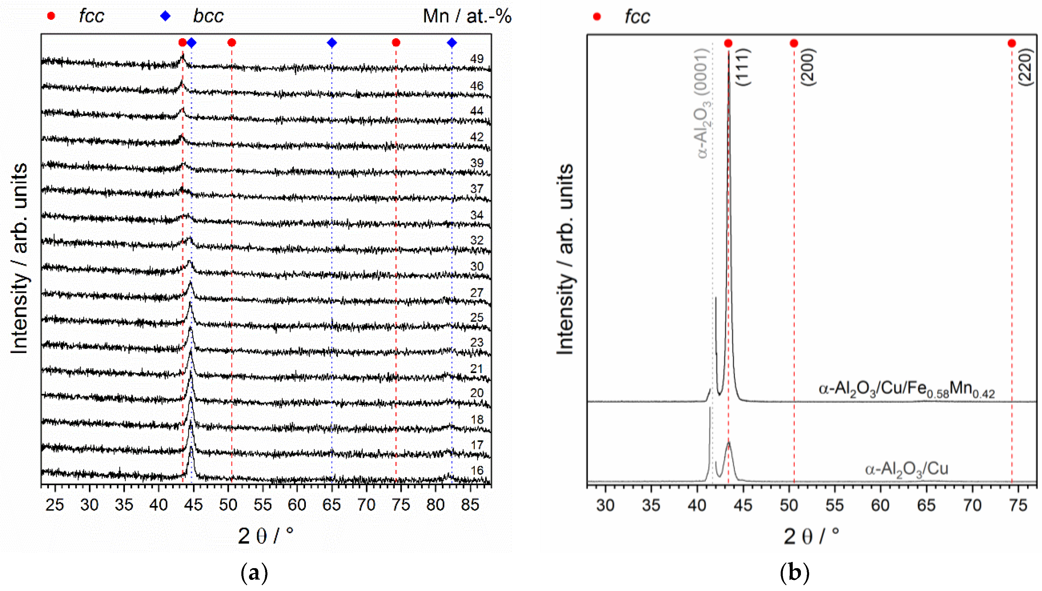
3.2. Experimental Validation

A 10 nm layer of Cu subsequently followed by a 100 nm combinatorial FeMn layer was synthesized on an α-Al2O3(0001) substrate and evaluated by EDX and spatially resolved XRD to identify the Mn content range, in which the desired fcc FeMn forms. Figure 2a shows the XRD scans (2θ-scans at fixed incidence angle ω) for Mn contents between 16 and 49 at. %. For Mn contents above 39 at. % the formation of phase pure fcc FeMn is observed. Lower Mn contents appear to facilitate the formation of an additional bcc phase and are thus excluded from further analysis. Figure 2b shows the Bragg-Brentano XRD scan of the fcc region of the α-Al2O3/Cu/FeMn sample, which is selected for TEM analysis (TEM-EDX: ~42 at. % Mn). For comparison, the XRD scan of a sole 10 nm Cu thin film (α-Al2O3/Cu)—deposited and measured under the same conditions—is included. Both Bragg-Brentano scans solely exhibit the (111) peak of the fcc structure. The intensity difference is caused by the difference in thin film thickness (110 nm for α-Al2O3/Cu/FeMn and 10 nm for α-Al2O3/Cu) and thus measured volume. Hence, the fcc FeMn layer as well as the Cu layer are highly (111) oriented and exhibit a very similar d111-value of about 2.08 Å. The presence of a (111) fibre texture was excluded by ϕ-scans (2θ = 43.39°, ω = θ°, χ = 20°) in the fcc region at ~42 at. % Mn. Figure S1 (Supplementary Material) shows the maximum intensities plotted in dependence of ϕ, exhibiting maximum intensities every 60° ϕ but minimum intensities in-between and thus refuting a fibre texture. Hence, XRD analysis indicates local epitaxial growth, which will be confirmed by high resolution techniques.
The surface roughness of the FeMn thin film is determined to be as low as Ra = 0.6 nm with a calculated standard deviation of 4% (based on ten individual measurements of 10 × 10 µm²; a representative surface area scan can be found in the Supplementary Material, Figure S2). Hence, the surface roughness is on the same order of magnitude as the one measured for the pristine α-Al2O3 substrate (Ra = 0.1 nm). Thus, a significant reduction of the surface roughness compared to the high temperature synthesis strategy resulting in surface roughness values of Ra = 58 nm [19] and larger [16,17] (film thickness ~2 µm) could be obtained.
The STEM high angle annular dark field (HAADF) image of the layer system α-Al2O3/Cu/Fe0.58Mn0.42 with the corresponding EDX line scan shown in Figure 3 confirms the chemical stacking of the layer system: The α-Al2O3 substrate is characterized by high Al K and O K intensities, while the nucleation layer shows a peak in Cu K intensity for a length of about 10 nm. The Cu layer is directly followed by the ~100 nm thick FeMn layer with correspondingly high Fe K and Mn K intensities. The uppermost region of the FeMn layer already shows significant intensities of Pt M and Ga K, which is an effect of the FIB preparation necessitating the deposition of a Pt protection layer in order to reduce Ga implantation. Spot EDX measurements of the Fe and Mn content in the thin film layer result in 58 ± 1 at. % and 42 ± 1 at. % Mn, respectively, which is close to the calculated Fe0.6Mn0.4 composition.
The SAED of the α-Al2O3/Cu/Fe0.58Mn0.42 layer system confirms that the α-Al2O3(0001) substrate is a chemically ordered structure and thus provides superstructure diffraction spots, as shown in the indexed diffraction pattern in Figure 4a. Figure 4b shows the diffraction pattern and an evaluation of the Cu/Fe0.58Mn0.42 layer. The Cu and the FeMn layer are not distinguishable and offer the same diffraction spots, confirming that they exhibit the same fcc structure as well as non-distinguishable lattice parameters. This was already indicated by the (macroscopic) XRD analysis discussed above, see Figure 2b. The fcc Fe0.58Mn0.42 is a chemically disordered solid solution, which is consistent with literature [25]. The orientation relationship between the α-Al2O3 substrate and the fcc Cu/Fe0.58Mn0.42 suggests (local) epitaxial growth and is determined as follows:
  • α-Al2O3 ( 0006 ) || Cu/Fe0.58Mn0.42 ( 1 ¯ 1 ¯ 1 ) [or ( 11 1 ¯ ) ] and
  • α-Al2O3 ( 0 3 ¯ 30 ) || Cu/Fe0.58Mn0.42 ( 2 2 ¯ 0 ) [or ( 2 ¯ 20 ) ]
The possibilities in square brackets are due to the rotational symmetry for a 180° rotation of the diffraction pattern. Furthermore, the inverted diffraction pattern of the layer system in Figure 4c reveals that the (small, focused) diffraction spots of the α-Al2O3 substrate are not positioned at the exact same positions as the (broad, unfocused) spots of the fcc Cu/Fe0.58Mn0.42 layer, indicating on the one hand that the (local) epitaxial growth is realized but also that the slightly different lattice plane spacing of α-Al2O3 and fcc Cu/Fe0.58Mn0.42 result in strain relaxation in the probed volume. Hence, we have demonstrated that fcc Fe0.58Mn0.42(111) can be grown epitaxially on fcc Cu(111) which in turn grows epitaxially on α-Al2O3(0001).
The low surface roughness of the 100 nm thick FeMn thin film, achieved by the local epitaxial growth on the Cu nucleation layer, allows for the formation of a flat (2D) interface between the fcc FeMn if another layer is deposited on top. This is a necessary step towards realizing the deposition of a bi- or multi-layered (multiphase) thin film model systems to allow for the systematic evaluation of interface dominated properties. These model systems are relevant to explore for example FeMn steels containing precipitates or secondary phases. The single phase model systems can benefit from the low surface roughness in terms of for example, a more accurate determination of mechanical properties by nanoindentation or other roughness-sensitive analysis techniques.

4. Conclusions

In conclusion, a low temperature deposition strategy for the growth of smooth fcc FeMn thin films was developed. Ab initio calculations suggest that the layer structure α-Al2O3(0001)/Cu(111) exhibits higher interfacial strength than MgO(001)/Cu(001) and is thus chosen as substrate/nucleation layer combination to enable (local) epitaxial growth of fcc Cu(111) on α-Al2O3(0001) as well as (local) epitaxial growth of fcc FeMn(111) on fcc Cu(111). The work of separation between Cu and Fe0.6Mn0.4 does not differ significantly between the two configurations studied, and, as such, is not decisive regarding the selection of the substrate system. However, the α-Al2O3(0001)/Cu(111) interface exhibits a more than six times higher work of separation (5.48 J/m²) than the MgO(001)/Cu(001) interface (0.85 J/m²) and hence strong interfacial bonding. This distinct difference in the calculated work of separation can be understood based on the Cu coordination at the interface, which is 1 between Cu and O for MgO(001)/Cu(001) but 3 for α-Al2O3(0001)/Cu(111).
The low temperature deposition strategy for the growth of smooth fcc FeMn thin films was critically appraised by synthesizing a 100 nm thick (combinatorial) FeMn thin film on a 10 nm Cu nucleation layer which was in turn deposited on an α-Al2O3(0001) substrate (α-Al2O3/Cu/FeMn). XRD confirms the phase formation of fcc FeMn for Mn contents above 39 at. %. The (local) epitaxial growth of fcc Fe0.58Mn0.42(111) on fcc Cu(111) on α-Al2O3(0001) is verified by TEM/SAED with the following orientation relationship: α-Al2O3 ( 0006 ) || Cu/Fe0.58Mn0.42 ( 1 ¯ 1 ¯ 1 ) and α-Al2O3 ( 0 3 ¯ 30 ) || Cu/Fe0.58Mn0.42 ( 2 2 ¯ 0 ) . The thin film exhibits the desired low surface roughness with Ra values as low as 0.6 nm, which is on the same order of magnitude as the α-Al2O3 substrate (Ra ~ 0.1 nm) and at least two orders of magnitude lower than the fcc FeMn based thin films deposited at high temperatures (Ra ≥ 58 nm). Thus, the introduced synthesis strategy opens the possibility of the successful implementation of thin film model systems for materials with interface dominated properties such as FeMn based steels containing κ-carbide precipitates.

Supplementary Materials

The following are available online at https://www.mdpi.com/2075-4701/8/6/384/s1.

Author Contributions

F.H., D.M. and J.M.S. conceived and designed the experiments and DFT calculations; D.M. designed and performed the DFT calculations; F.H., P.J.P. and A.L.R. performed the sputtering experiments as well as XRD, EDX and surface roughness analysis; M.H. performed the TEM sample preparation and B.V. conceived and performed the TEM analysis; D.M. and J.M.S. initiated and supervised the project; all authors contributed to the interpretation of the data and the writing of the paper.

Funding

This research was funded by the Deutsche Forschungsgemeinschaft (DFG) within the Collaborative Research Center (SFB) 761 “Steel ab initio”.

Acknowledgments

Simulations were performed with computing resources granted by JARA-HPC from RWTH Aachen University under project JARA0152.

Conflicts of Interest

The authors declare no conflict of interest.

References

  1. Frommeyer, G.; Brux, U.; Neumann, P. Supra-ductile and high-strength manganese-TRIP/TWIP steels for high energy absorption purposes. ISIJ Int. 2003, 43, 438–446. [Google Scholar] [CrossRef]
  2. Peng, C.T.; Callaghan, M.D.; Li, H.J.; Yan, K.; Liss, K.D.; Ngo, T.D.; Mendis, P.A.; Choi, C.H. On the compression behavior of an austenitic Fe-18Mn-0.6C-1.5Al twinning-induced plasticity steel. Steel Res. Int. 2013, 84, 1281–1287. [Google Scholar] [CrossRef]
  3. Gutierrez-Urrutia, I.; Raabe, D. Dislocation and twin substructure evolution during strain hardening of an Fe-22 wt. % Mn-0.6 wt. % C TWIP steel observed by electron channeling contrast imaging. Acta Mater. 2011, 59, 6449–6462. [Google Scholar] [CrossRef]
  4. Gebhardt, T.; Music, D.; Hallstedt, B.; Ekholm, M.; Abrikosov, I.A.; Vitos, L.; Schneider, J.M. Ab initio lattice stability of fcc and hcp Fe-Mn random alloys. J. Phys. Condes. Matter 2010, 22, 295402. [Google Scholar] [CrossRef] [PubMed]
  5. Gebhardt, T.; Music, D.; Takahashi, T.; Schneider, J.M. Combinatorial thin film materials science: From alloy discovery and optimization to alloy design. Thin Solid Films 2012, 520, 5491–5499. [Google Scholar] [CrossRef]
  6. Gutierrez-Urrutia, I.; Raabe, D. Influence of Al content and precipitation state on the mechanical behavior of austenitic high-Mn low-density steels. Scr. Mater. 2013, 68, 343–347. [Google Scholar] [CrossRef]
  7. Timmerscheidt, T.; Dey, P.; Bogdanovski, D.; von Appen, J.; Hickel, T.; Neugebauer, J.; Dronskowski, R. The role of κ-carbides as hydrogen traps in high-Mn steels. Metals 2017, 7, 264. [Google Scholar] [CrossRef]
  8. Kuch, W.; Chelaru, L.I.; Offi, F.; Wang, J.; Kotsugi, M.; Kirschner, J. Tuning the magnetic coupling across ultrathin antiferromagnetic films by controlling atomic-scale roughness. Nat. Mater. 2006, 5, 128–133. [Google Scholar] [CrossRef] [PubMed]
  9. Lenssen, K.M.H.; van Kesteren, H.W.; Rijks, T.; Kools, J.C.S.; de Nooijer, M.C.; Coehoorn, R.; Folkerts, W. Giant magnetoresistance and its application in recording heads. Sens. Actuator A Phys. 1997, 60, 90–97. [Google Scholar] [CrossRef]
  10. Savin, P.; Guzman, J.; Lepalovskij, V.; Svalov, A.; Kurlyandskaya, G.; Asenjo, A.; Vas’kovskiy, V.; Vazquez, M. Exchange bias in sputtered FeNi/FeMn systems: Effect of short low-temperature heat treatments. J. Magn. Magn. Mater. 2016, 402, 49–54. [Google Scholar] [CrossRef]
  11. Svalov, A.; Savin, P.; Lepalovskij, V.; Larranaga, A.; Vas’kovskiy, V.; Garcia-Arribas, A.; Kurlyandskaya, G. Tailoring the exchange bias in FeNi/FeMn bilayers by heat treatment and FeMn surface oxidation. IEEE Trans. Magn. 2014, 50, 1–4. [Google Scholar] [CrossRef]
  12. Stocks, G.M.; Shelton, W.A.; Schulthess, T.C.; Ujfalussy, B.; Butler, W.H.; Canning, A. On the magnetic structure of gamma-FeMn alloys. J. Appl. Phys. 2002, 91, 7355–7357. [Google Scholar] [CrossRef]
  13. Binasch, G.; Grünberg, P.; Saurenbach, F.; Zinn, W. Enhanced magnetoresistance in layered magnetic structures with antiferromagnetic interlayer exchange. Phys. Rev. B 1989, 39, 4828–4830. [Google Scholar] [CrossRef]
  14. Sawada, H.; Taniguchi, S.; Kawakami, K.; Ozaki, T. Transition of the interface between iron and carbide precipitate from coherent to semi-coherent. Metals 2017, 7, 277. [Google Scholar] [CrossRef]
  15. Schmidt, M.; Grafe, J.; Audehm, P.; Phillipp, F.; Schutz, G.; Goering, E. Preparation and characterisation of epitaxial Pt/Cu/FeMn/Co thin films on (100)-oriented MgO single crystals. Phys. Status Solidi A 2015, 212, 2114–2123. [Google Scholar] [CrossRef]
  16. Reeh, S.; Music, D.; Gebhardt, T.; Kasprzak, M.; Japel, T.; Zaefferer, S.; Raabe, D.; Richter, S.; Schwedt, A.; Mayer, J.; et al. Elastic properties of face-centred cubic Fe-Mn-C studied by nanoindentation and ab initio calculations. Acta Mater. 2012, 60, 6025–6032. [Google Scholar] [CrossRef]
  17. Reeh, S.; Kasprzak, M.; Klusmann, C.D.; Stalf, F.; Music, D.; Ekholm, M.; Abrikosov, I.A.; Schneider, J.M. Elastic properties of fcc Fe-Mn-X (X = Cr, Co, Ni, Cu) alloys studied by the combinatorial thin film approach and ab initio calculations. J. Phys. Condens. Matter 2013, 25, 245401. [Google Scholar] [CrossRef] [PubMed]
  18. Gebhardt, T.; Music, D.; Ekholm, M.; Abrikosov, I.A.; von Appen, J.; Dronskowski, R.; Wagner, D.; Mayer, J.; Schneider, J.M. Influence of chemical composition and magnetic effects on the elastic properties of fcc Fe-Mn alloys. Acta Mater. 2011, 59, 1493–1501. [Google Scholar] [CrossRef]
  19. Gebhardt, T.; Music, D.; Kossmann, D.; Ekholm, M.; Abrikosov, I.A.; Vitos, L.; Schneider, J.M. Elastic properties of fcc Fe-Mn-X (X = Al, Si) alloys studied by theory and experiment. Acta Mater. 2011, 59, 3145–3155. [Google Scholar] [CrossRef]
  20. Offi, F.; Kuch, W.; Kirschner, J. Structural and magnetic properties of FexMn1−x thin films on Cu(001) and on Co/Cu(001). Phys. Rev. B 2002, 66, 064419. [Google Scholar] [CrossRef]
  21. Kuch, W.; Chelaru, L.I.; Kirschner, J. Surface morphology of antiferromagnetic Fe50Mn50 layers on Cu(001). Surf. Sci. 2004, 566–568, 221–225. [Google Scholar] [CrossRef]
  22. Wuttig, M.; Feldmann, B.; Flores, T. The correlation between structure and magnetism for ultrathin metal films and surface alloys. Surf. Sci. 1995, 331–333, 659–672. [Google Scholar] [CrossRef]
  23. Allegranza, O.; Chen, M.M. Effect of substrate and antiferromagnetic films thickness on exchange-bias field (invited). J. Appl. Phys. 1993, 73, 6218–6222. [Google Scholar] [CrossRef]
  24. Sankaranarayanan, V.K.; Yoon, S.M.; Kim, D.Y.; Kim, C.O.; Kim, C.G. Exchange bias in NiFe/FeMn/NiFe trilayers. J. Appl. Phys. 2004, 96, 7428–7434. [Google Scholar] [CrossRef]
  25. Ekholm, M.; Abrikosov, I.A. Structural and magnetic ground-state properties of gamma-FeMn alloys from ab initio calculations. Phys. Rev. B 2011, 84, 104423. [Google Scholar] [CrossRef]
  26. Cu Crystal Structure; Datasheet from “Pauling File Multinaries Edition—2012” in Springermaterials; Springer: Berlin/Heidelberg, Germany; Material Phases Data System (MPDS): Vitznau, Switzerland; National Institute for Materials Science (NIMS): Tsukuba, Japan; Available online: http://materials.Springer.Com/isp/crystallographic/docs/sd_0250160 (accessed on 28 November.2017).
  27. Predel, B. Fe-Mn (iron-manganese): Datasheet from landolt-börnstein—Group iv physical chemistry volume 5e: “Dy-Er—Fr-Mo”. In SpringerMaterials; Springer: Berlin/Heidelberg, Germany, 1995. [Google Scholar]
  28. MgO Crystal Structure; Datasheet from “Pauling File Multinaries Edition—2012” in Springermaterials; Springer: Berlin/Heidelberg, Germany; Material Phases Data System (MPDS): Vitznau, Switzerland; National Institute for Materials Science (NIMS): Tsukuba, Japan; Available online: http://materials.Springer.Com/isp/crystallographic/docs/sd_0305005 (accessed on 28 November 2017).
  29. α-Al2O3 (Al2O3 Cor) Crystal Structure; Datasheet from “Pauling File Multinaries Edition—2012” in Springermaterials; Springer: Berlin/Heidelberg, Germany; Material Phases Data System (MPDS): Vitznau, Switzerland; National Institute for Materials Science (NIMS): Tsukuba, Japan; Available online: http://materials.Springer.Com/isp/crystallographic/docs/sd_0453386 (accessed on 28 November 2017).
  30. He, J.-W.; Møller, P.J. Epitaxial and electronic structures of ultra-thin copper films on MgO crystal surfaces. Surf. Sci. 1986, 178, 934–942. [Google Scholar] [CrossRef]
  31. Oh, S.H.; Scheu, C.; Wagner, T.; Tchernychova, E.; Ruhle, M. Epitaxy and bonding of Cu films on oxygen-terminated alpha-Al2O3(0001) surfaces. Acta Mater. 2006, 54, 2685–2696. [Google Scholar] [CrossRef]
  32. Sigumonrong, D.P.; Zhang, J.; Zhou, Y.; Music, D.; Emmerlich, J.; Mayer, J.; Schneider, J.M. Interfacial structure of V2AlC thin films deposited on (11-20)-sapphire. Scr. Mater. 2011, 64, 347–350. [Google Scholar] [CrossRef]
  33. Schönjahn, C.; Donohue, L.A.; Lewis, D.B.; Münz, W.-D.; Twesten, R.D.; Petrov, I. Enhanced adhesion through local epitaxy of transition-metal nitride coatings on ferritic steel promoted by metal ion etching in a combined cathodic arc/unbalanced magnetron deposition system. J. Vac. Sci. Technol. A 2000, 18, 1718–1723. [Google Scholar] [CrossRef]
  34. Petrov, I.; Losbichler, P.; Bergstrom, D.; Greene, J.E.; Münz, W.D.; Hurkmans, T.; Trinh, T. Ion-assisted growth of Ti1−xAlxN/Ti1−yNbyN multilayers by combined cathodic-arc/magnetron-sputter deposition. Thin Solid Films 1997, 302, 179–192. [Google Scholar] [CrossRef]
  35. Gao, Y.; Leiste, H.; Ulrich, S.; Stueber, M. Synthesis of local epitaxial α-(Cr1−xAlx)2O3 thin films (0.08 ≤ x ≤ 0.16) on α-Al2O3 substrates by r.f. Magnetron sputtering. Thin Solid Films 2017, 644, 129–137. [Google Scholar] [CrossRef]
  36. Hohenberg, P.; Kohn, W. Inhomogeneous electron gas. Phys. Rev. 1964, 136, B864. [Google Scholar] [CrossRef]
  37. Kresse, G.; Hafner, J. Ab initio molecular dynamics for open-shell transition metals. Phys. Rev. B 1993, 48, 13115. [Google Scholar] [CrossRef]
  38. Kresse, G.; Hafner, J. Ab initio molecular-dynamics simulation of the liquid-metal-amorphous-semiconductor transition in germanium. Phys. Rev. B 1994, 49, 14251. [Google Scholar] [CrossRef]
  39. Kresse, G.; Joubert, D. From ultrasoft pseudopotentials to the projector augmented wave method. Phys. Rev. B 1999, 59, 1758. [Google Scholar] [CrossRef]
  40. Perdew, J.P.; Burke, K.; Ernzerhof, M. Generalized gradient approximation made simple. Phys. Rev. Lett. 1996, 77, 3865. [Google Scholar] [CrossRef] [PubMed]
  41. Blöchl, P.E. Projector augmented-wave method. Phys. Rev. B 1994, 50, 17953. [Google Scholar] [CrossRef]
  42. Monkhorst, H.J.; Pack, J.D. Special points for brillouin-zone integrations. Phys. Rev. B 1976, 13, 5188. [Google Scholar] [CrossRef]
  43. Zunger, A.; Wei, S.-H.; Ferreira, L.G.; Bernard, J.E. Special quasirandom structures. Phys. Rev. Lett. 1990, 65, 353. [Google Scholar] [CrossRef] [PubMed]
  44. Abrikosov, I.A.; Niklasson, A.M.N.; Simak, S.I.; Johansson, B.; Ruban, A.V.; Skriver, H.L. Order-N green’s function technique for local environment effects in alloys. Phys. Rev. Lett. 1996, 76, 4203. [Google Scholar] [CrossRef] [PubMed] [Green Version]
  45. Abrikosov, I.A.; Simak, S.I.; Johansson, B.; Ruban, A.V.; Skriver, H.L. Locally self-consistent green’s function approach to the electronic structure problem. Phys. Rev. B 1997, 56, 9319. [Google Scholar] [CrossRef] [Green Version]
  46. Cowley, J.M. X-ray measurement of order in single crystals of Cu3Au. J. Appl. Phys. 1950, 21, 24–30. [Google Scholar] [CrossRef]
  47. Lin, Z.; Bristowe, P.D. Microscopic characteristics of the Ag(111)/ZnO(0001) interface present in optical coatings. Phys. Rev. B 2007, 75, 205423. [Google Scholar] [CrossRef]
  48. Matsunaka, D.; Shibutani, Y. Electronic states and adhesion properties at metal/MgO incoherent interfaces: First-principles calculations. Phys. Rev. B 2008, 77, 165435. [Google Scholar] [CrossRef]
  49. Hashibon, A.; Elsässer, C.; Rühle, M. Structure at abrupt copper–alumina interfaces: An ab initio study. Acta Mater. 2005, 53, 5323–5332. [Google Scholar] [CrossRef]
  50. Lazar, P.; Otyepka, M. Accurate surface energies from first principles. Phys. Rev. B 2015, 91, 115402. [Google Scholar] [CrossRef]
  51. Sigumonrong, D.P.; Music, D.; Schneider, J.M. Efficient supercell design for surface and interface calculations of hexagonal phases: α -Al2O3 case study. Comput. Mater. Sci. 2011, 50, 1197–1201. [Google Scholar] [CrossRef]
  52. Music, D.; Lange, D.; Raumann, L.; Baben, M.t.; von Fragstein, F.; Schneider, J.M. Polypropylene–MALN (M = Ti, Cr) interface interactions. Surf. Sci. 2012, 606, 986–989. [Google Scholar] [CrossRef]
  53. Music, D.; Schmidt, P.; Saksena, A. Experimental and theoretical exploration of mechanical stability of Pt/NbO2 interfaces for thermoelectric applications. J. Phys. D Appl. Phys. 2017, 50, 455502. [Google Scholar] [CrossRef]
  54. Batirev, I.G.; Alavi, A.; Finnis, M.W.; Deutsch, T. First-principles calculations of the ideal cleavage energy of bulk niobium(111)/α-alumina(0001) interfaces. Phys. Rev. Lett. 1999, 82, 1510–1513. [Google Scholar] [CrossRef]
  55. Popov, M.N.; Spitaler, J.; Mühlbacher, M.; Walter, C.; Keckes, J.; Mitterer, C.; Draxl, C. TiO2(100)/Al2O3(0001) interface: A first-principles study supported by experiment. Phys. Rev. B 2012, 86, 205309. [Google Scholar] [CrossRef]
  56. Qi, Y.; Hector, L.G. Hydrogen effect on adhesion and adhesive transfer at aluminum/diamond interfaces. Phys. Rev. B 2003, 68, 201403. [Google Scholar] [CrossRef]
  57. Gong, H.R.; Liu, Y.; Tang, H.P.; Xiang, C.S. Bond strength and electronic structures of coherent Ir/Ir3Zr interfaces. Appl. Phys. Lett. 2008, 92, 211914. [Google Scholar] [CrossRef]
  58. Eyert, V.; Schwingenschlögl, U.; Eckern, U. Covalent bonding and hybridization effects in the corundum-type transition-metal oxides V2O3 and Ti2O3. EPL (Europhys. Lett.) 2005, 70, 782. [Google Scholar] [CrossRef]
Figure 1. Structural models of (a) MgO(001)/Cu(001)/Fe0.6Mn0.4(001) and (b) α-Al2O3(0001)/Cu(111)/Fe0.6Mn0.4(111), each with corresponding electron density distribution in a ( 11 2 ¯ 0 ) plane of the substrate. The work of separation (WS) and bond length (d) at the interfaces are also provided.
Metals 08 00384 g001
Figure 2. (a) X-ray diffraction (XRD) scans (2θ-scans at fixed incidence angle ω) of α-Al2O3/Cu/FeMn in dependence of the Mn content of the FeMn layer; (b) XRD scan (Bragg-Brentano) of α-Al2O3/Cu/Fe0.58Mn0.42, which is chosen for transmission electron microscopy (TEM) analysis (comparison: α-Al2O3/Cu without FeMn layer).
Metals 08 00384 g002
Figure 3. Scanning transmission electron microscopy (STEM) high angle annular dark field (HAADF) image of the layer system α-Al2O3/Cu/Fe0.58Mn0.42 with corresponding energy dispersive X-ray (EDX) line scan including the Al K, O K, Cu K, Fe K, Mn K, Pt M and Ga K intensities. The intensity signal is not corrected for peak overlapping.
Metals 08 00384 g003
Figure 4. Indexed diffraction pattern of (a) α-Al2O3 substrate (zone axis [ 2 1 ¯ 1 ¯ 0 ] ); (b) fcc Cu/Fe0.58Mn0.42 layer (zone axis [ 112 ] ); (c) Diffraction pattern of the layer system α-Al2O3/Cu/Fe0.58Mn0.42 (fcc and α-Al2O3 diffraction spots are labelled with red circles and blue squares, respectively).
Metals 08 00384 g004

