Liquation Cracking in the Heat-Affected Zone of IN738 Superalloy Weld


1
Institute of Materials Engineering, National Taiwan Ocean University, Keelung 20224, Taiwan
2
Nuclear Fuels and Materials Division, Institute of Nuclear Energy Research, Taoyuan 32546, Taiwan
3
Department of Materials Science and Engineering, National Taiwan University, Taipei 10617, Taiwan
*
Author to whom correspondence should be addressed.
Metals 2018, 8(6), 387; https://doi.org/10.3390/met8060387
Submission received: 7 May 2018
/
Revised: 24 May 2018
/
Accepted: 25 May 2018
/
Published: 27 May 2018
(This article belongs to the Special Issue Science, Characterization and Technology of Joining and Welding)
Abstract
:The main scope of this study investigated the occurrence of liquation cracking in the heat-affected zone (HAZ) of IN738 superalloy weld, IN738 is widely used in gas turbine blades in land-based power plants. Microstructural examinations showed considerable amounts of γ’ uniformly precipitated in the γ matrix. Electron probe microanalysis (EPMA) maps showed the γ-γ’ colonies were rich in Al and Ti, but lean in other alloy elements. Moreover, the metal carbides (MC), fine borides (M3B2 and M5B3), η-Ni3Ti, σ (Cr-Co) and lamellar Ni7Zr2 intermetallic compounds could be found at the interdendritic boundaries. The fracture morphologies and the corresponding EPMA maps confirmed that the liquation cracking in the HAZ of the IN738 superalloy weld resulted from the presence of complex microconstituents at the interdendritic boundaries.
1. Introduction
The superior tensile strength, creep and oxidation resistance at elevated temperature make Ni-base superalloys used extensively in industrial gas turbines [1]. A wide range of Ni-base superalloys, from solid solution-strengthened to highly-alloyed precipitation-hardened materials, have been achieved to satisfy the requirements of high-temperature performance and environmental corrosion resistance. IN738, a cast Ni-base superalloy, is strengthened by extensive precipitation of γ’ (Ni3(Al,Ti)) and metal carbides (MC) to achieve excellent mechanical properties at elevated temperature [2,3]. After a long term of service at elevated temperature and high stress, the turbine blades eventually suffer from fatigue and creep damages, which degrade the microstructures and/or introduce defects into the components. To lower the life cost during service, less expensive means are developed as an alternative to replace new components. Furthermore, rejuvenation treatments are reported to be able to restore the microstructures and mechanical properties of degraded superalloys [4,5,6]. More often, repair-welding is chosen as the major way to refurbish cracked or damaged blades in gas turbines [1].
Traditionally, repair-welding of Ni-base superalloys has been conducted by gas tungsten arc welding (GTAW) processes [7,8,9,10,11]. However, the precipitation-hardened Ni-base superalloys are very sensitive to hot cracking in the heat-affected zone (HAZ) and fusion zone (FZ) during welding [7,8,12,13,14]. IN738 contains considerable amounts of Al and Ti, which is known for its poor weldability. Liquation cracking of precipitation-hardened Ni-base superalloys is strongly dependent on forming low-melting liquid film at the grain boundaries of the HAZ. The final solidified products with low melting point at the grain boundaries of cast Ni-base superalloys, such as M5B3 and M2B borides, γ-γ’ (Ni3(Al,Ti)) eutectics, MC carbides, and some other intermetallic compounds, are responsible for their high cracking susceptibility [15,16,17,18,19]. Cracking caused by the HAZ liquation in the as-welded condition is exacerbated by subsequent postweld heat treatment [20]. Preheating at sufficiently high temperatures before welding reduces thermally induced stress. Such preheating more effectively prevents cracking of IN738LC superalloy than does controlling the material ductility through preweld heat treatment [21].
To date, many efforts have been made to eliminate or reduce the HAZ cracking of precipitation-hardened Ni-base superalloys through the control of primary microstructures by preweld heat treatment [18,19,22,23,24], by laser [12,18,20,23,25,26,27] or electron beam [28,29] welding processes, or by using filler with lower Al + Ti content [30,31,32]. In practical applications, the use of under matched filler or low heat-input welding processes to reduce weld-shrinkage stress are able to lower cracking in those Ni-base superalloys with poor weldability. Hot isostatic pressing is effective to heal all the cracks present in FZ and HAZ of laser-repaired CM247LC superalloy weld [33]. The aim of this work was to investigate the influence of grain boundary constitutents on the hot cracking sensitivity of IN738 alloy. The microstructures and chemical compositions of the microconstituents in cast IN738 were investigated. The coverings on liquated crack surfaces were examined and their compositions were determined. Furthermore, the relationship between microstructural features and the hot cracking mechanism of the repaired specimens was correlated with the inherent solidification products at the interdendritic boundaries of the cast IN738 superalloy.
2. Materials and Experimental Procedures
The IN738 alloy ingot used in this work, which was melt and cast in vacuum, had a diameter of 75 mm. Disc samples with a thickness of 5 mm were wire-cut from the vacuum-melted ingot. The chemical compositions of the experimental material in wt. % were: 0.17 C, 3.5 Al, 3.5 Ti, 16 Cr, 8.5 Co, 1.7 Mo, 2.5 W, 0.8 Nb, 0.1 Zr, 0.01 B, and the balance Ni. To relieve the residual stress in the as-cast sample, the samples were heated at 1050 °C for 5 h in high vacuum. GTAW was used to perform bead-on-plate welding in this study. The welding parameters included a welding current of 60 A, welding voltage of 10 V, and travel speed of 100 mm/min. After welding, the samples were cut either parallel or normal to the FZ. The welds experienced a standard metallographic preparation, and great attentions were paid to the HAZ microcracks.
Microstructures of the substrate and weldment were examined using a JSM-7100F field emission scanning electron microscope (FESEM, JEOL Ltd., Tokyo, Japan). Chemical compositions of various phases at the solidified boundaries were measured using either an X-MaxN energy-dispersive spectrometer (EDS, Oxford Instruments, Abingdon, UK) or a JXA-8200 electron probe micro-analyzer (EPMA, JEOL Ltd., Tokyo, Japan) equipped in the SEM. D2 Phaser X-ray diffraction (XRD, Bruker, Karlsruhe, Germany) using Cu-Kα radiation was employed to reveal various phases in the sample. In the XRD analysis, the tested samples wire-cut from the IN-738 ingot was approximately 10 mm in width and 20 mm in length. Although the analyzed region varies with the 2θ angle, it changed not much when 2θ varied between 30° and 80° [34]. The fracture features of the cracked specimens were also inspected by a FESEM. The crystallographic analyses of various phases at solidification boundaries were investigated by using an FESEM equipped with a detector of NordlysMax2 electron backscatter diffraction (EBSD, Oxford Instruments, Abingdon, UK).
3. Results
3.1. Microstructural Examinations
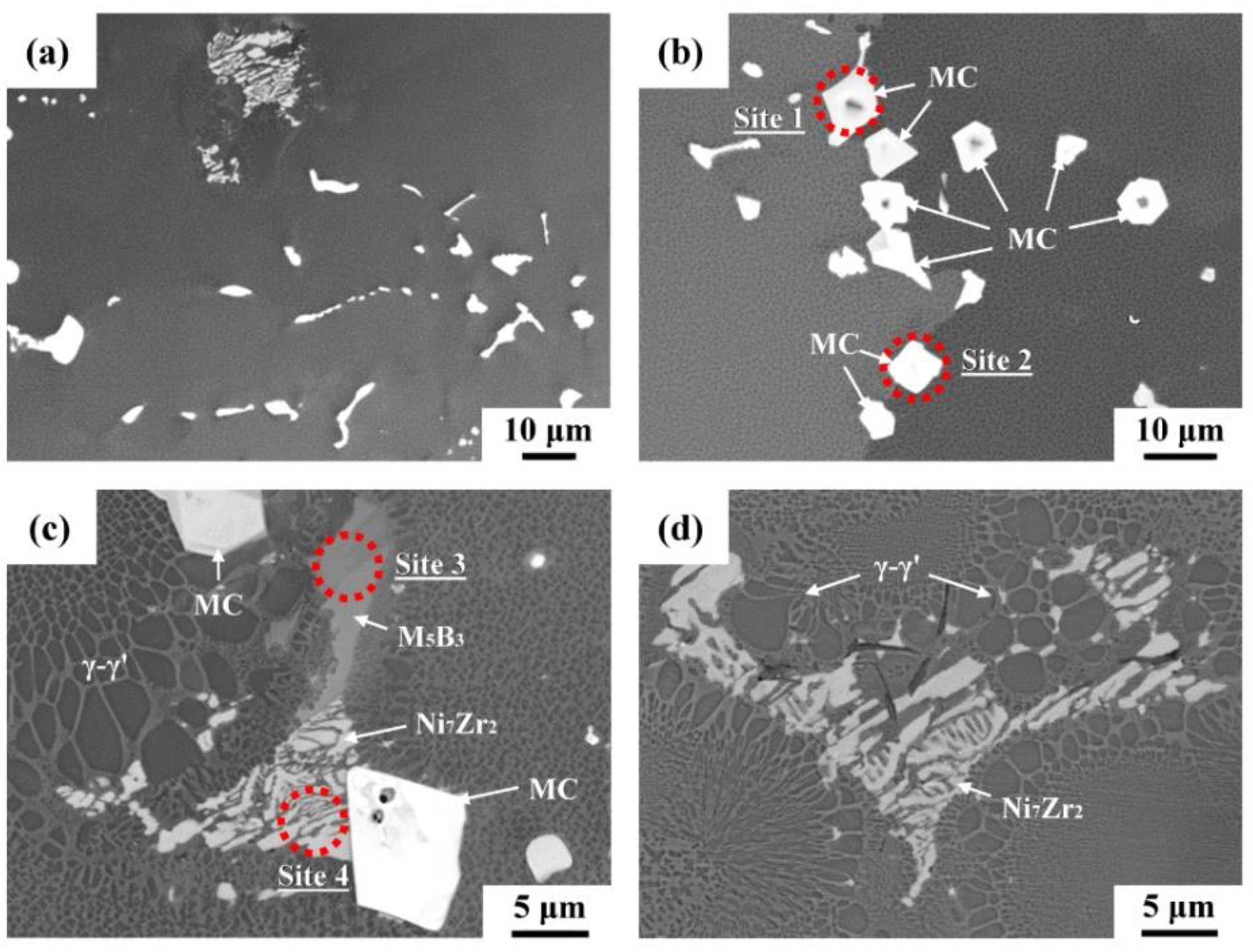
The back-scatter electron (BSE) images can be used to distinguish solidification products in a cast superalloy according to their image brightness or phase contrast. Figure 1 presents the SEM micrographs in BSE images, showing the microstructures of the cast IN738 alloy. Regarding the image brightness and phase contrast of the interdendritic microconstituents, the γ-γ’ colonies and γ matrix are revealed by high darkness in the figure. The segregation of carbide-forming (Nb, Ta, Ti) elements resulted in the formation of MC carbides, which are shown by high brightness. As shown in Figure 1a,b, MC carbides in different sizes and morphologies were the primary second phase in the cast alloy. The MC carbides were in different shapes: irregular, island-like, blocky, or Chinese-script. Moreover, lamellar eutectics were more likely to be found in the central part of the ingot. At higher magnification (Figure 1c,d), lamellar eutectics were observed nearby the γ-γ’ eutectic colonies, indicating the formation of low-melting microconstituents along solidified boundaries. A few fine white phases were found in the narrow boundaries between γ-γ’ colonies (Figure 1c,d). The lamellar eutectics were not as bright as the MC carbides, possibly due to lower concentrations of heavy elements in the former than those in the latter. In addition, the grain boundary product of gray color in Figure 1c was deduced to be boride. The fine particles at the boundaries between γ-γ’ colonies were likely fine MC carbides. The compositions and structures of those microconstituents would be confirmed below.
EPMA was used to determine the chemical compositions of the microconstituents at the interdendritic boundaries, as shown in Figure 1. Table 1 lists chemical compositions (in at. %) of the EPMA analysis, which were obtained at various locations displayed in Figure 1b,c. As illustrated in Table 1, MC carbides (Figure 1b, sites 1 and 2) were rich in Ti and alloyed with additional Ta and Nb. Because high Nb and Ta concentrations were observed in the MC carbides, the carbides naturally exhibited higher brightness in the BSE image. EDS analysis was also used to screen the chemical compositions of the carbides of different morphologies, which could be located inter- and intragranularly. All carbides were composed of the main alloy elements of Ti, Ta, and Nb. Figure 1c illustrates complex microconstituents ahead of the γ-γ’ eutectic colony, including a gray blocky phase (site 3) and white lamellar eutectic (site 4). The EPMA analysis results showed that the gray blocky phase comprised of high boron concentration, and enriched in Cr and Mo. It was reasonable to deduce that the gray blocky phase was Cr-Mo borides. Furthermore, the bright lamellar eutectic showed the high segregation of Zr along with high Ni content. The low alloy contents of the measurement at site 4 were due to the high yield volume of the detected site relative to the size of the lamellar structure. It was deduced that the bright lamellar eutectic could be intermetallic compound.
3.2. Phase Identification by XRD
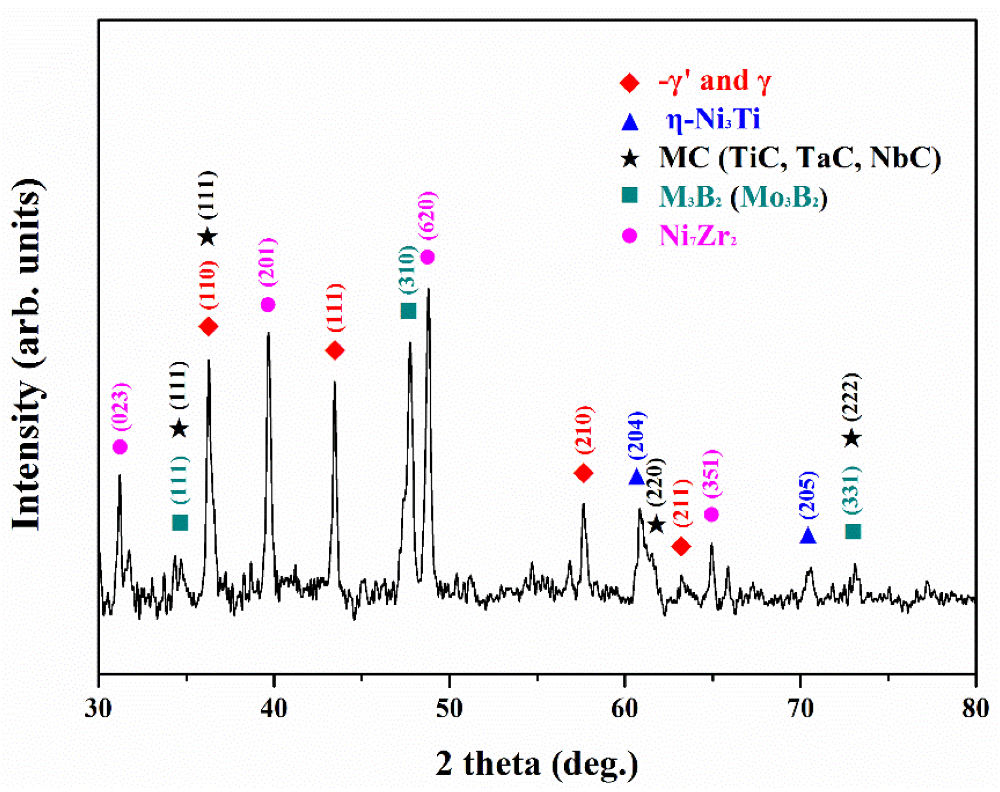
Figure 2 presents the XRD patterns of various phases in the cast IN738 substrate or base metal. The results indicated that MC carbides, M3B2 borides, η-Ni3Ti and Ni7Zr2 intermetallics associated with γ’ precipitates in the γ matrix, suggesting that the segregation of alloy elements during solidification caused the formation of many solidification products in the cast superalloy. According to previous research [7,8,12,14], different grain boundary constituents, such as MC carbide, M2SC sulphocarbide, Cr-Mo boride, Ni-Zr intermetallics, and γ-γ’ (Ni3(Al,Ti)) eutectic have been observed in IN738/IN738LC superalloys. In this study, η-Ni3Ti was also detected in the alloy. The presence of these final solidification products along interdendritic boundaries significantly deteriorated the weldability of cast IN738 superalloy.
3.3. Microconstituents Identified by EBSD
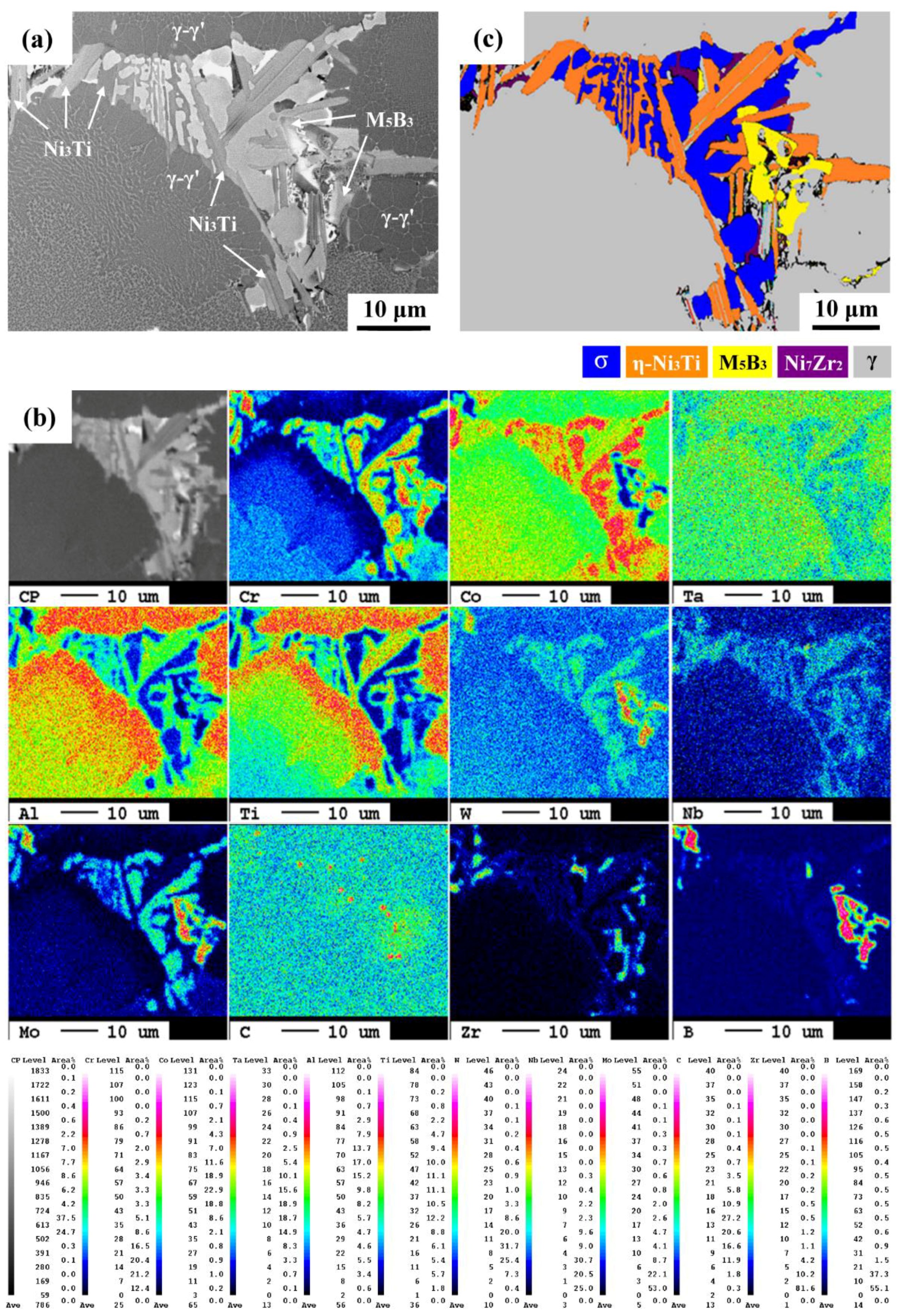
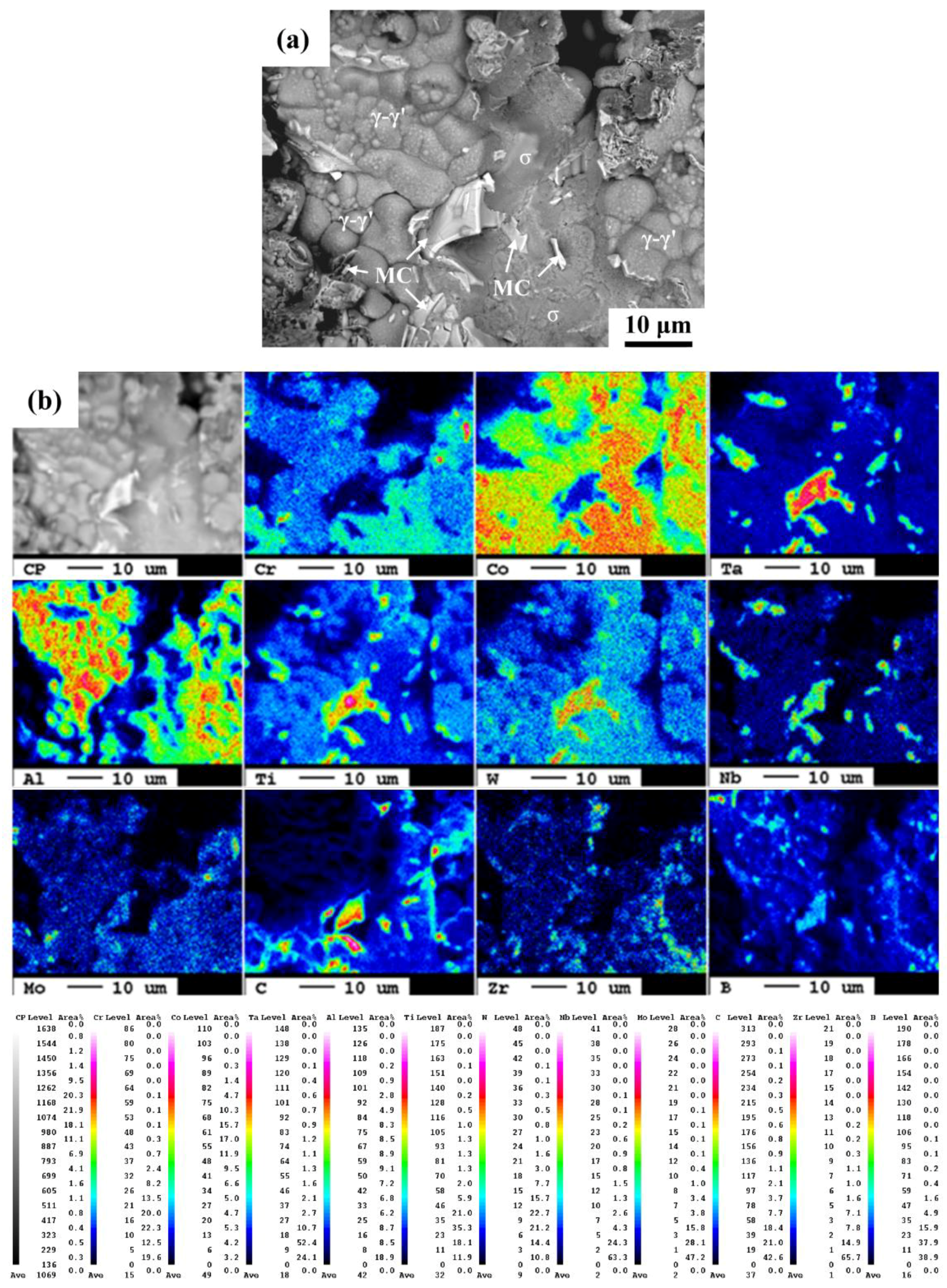
Figure 3 illustrates BSE image, the elemental mappings of EPMA and EBSD crystallographic map in order to identify various phases at the interdendritic boundary. In the BSE image (Figure 3a), the solidification products can be distinguished by image contrast. Additionally, the elemental maps (Figure 3b) illustrate the distributions of various elements in the microconstituents determined by EPMA. A bright color indicates higher count numbers of an element than does a dark one. EBSD map (Figure 3c) provides crystallographic data of different phases in the microconstituents. As shown in Figure 3a, the BSE image showed complex products formed nearby the dendrite boundary (Figure 3a). Both γ-γ’ colonies and γ matrix were in relatively high darkness in the figure. Isolated slender white phase, lamellar eutectic gray phase, and blocky gray product were also observed in Figure 3a. EPMA maps revealed that the γ-γ’ eutectic colonies were significantly enriched in Al and Ti as shown in high-intensity red (Figure 3b). The strong segregation of Al and Ti into the γ-γ’ eutectic colonies ahead of the final solidification products was also reported. Although the intensity of the Ta map was weak, it still showed the tendency of segregation to the γ-γ’ colonies. The C map was related to the sites of MC carbides, which showed the formation of fine, isolated carbides inter-dispersed in the grain boundary products. EPMA mappings displayed the co-segregation of B, Mo, Cr and W, which was expected to promote the formation of island-like Cr-Mo-W borides as shown in Figure 3a. It was also noted that a severe segregation of Co with Cr, Mo and W into the solidification products, which occupied a great fraction in this analysis. Moreover, according to the Ti and Nb maps, the distribution of Ti in the microconstituents was coincident with that of Nb therein. In addition, high Zr intensity was only observed in certain sites in the microconstituents of a slender form, as shown in Figure 3b.
The EBSD map (Figure 3c) showed the distributions of distinct phases in the solidification product. The co-segregation of B, Cr, Mo and W assisted the formation of M5B3 (CrMoW)5B3 borides, shown in yellow in Figure 3c. Additionally, the lamellar η-Ni3Ti, indicated by orange, has previously been pointed out in studies of Ni-Co superalloy and IN738 [35,36,37]. Although the Nb and Al intensity in the microconstituents was not so intense (Figure 3b), the distribution of Nb and Al in the solidification product was consistent with that of Ti. It was deduced that Nb and Al were partitioned into η-Ni3Ti (η-Ni3(TiAlNb)) intermetallic compound. Besides, locations with high Zr intensity were associated with the formation of Ni7Zr2 intermetallics, indicated by purple in the EBSD crystallographic map. EPMA mappings in this work showed a very high Co intensity in the solidification products. Basically, co-segregation of Co, Cr, Mo and W, which was confirmed by EPMA mappings, enhanced the formation of σ (CrCo) phase, as shown by dark blue in the EBSD map. Nodular σ phase has also been reported to nucleate and grow from the interdendritic liquid [37]. The result indicated that the chemical compositions of every phase in the terminal solidification products were quite complex. Compounds or precipitates predicted by the binary phase diagram were frequently alloyed with the third or even fourth elements.
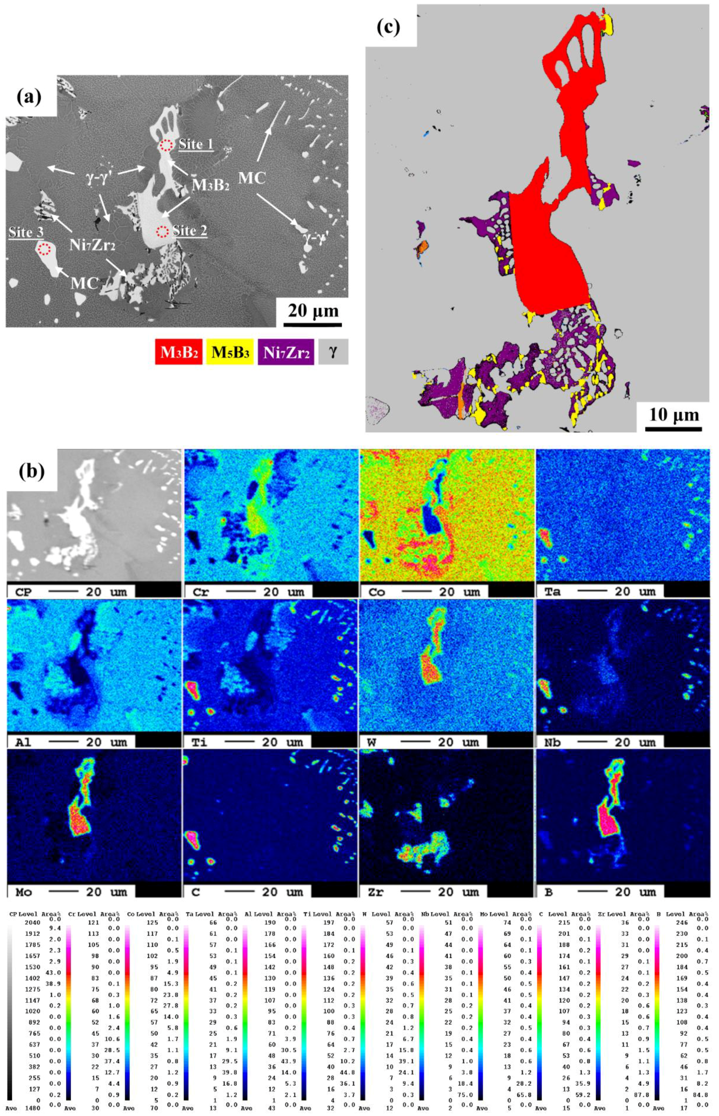
The solidification products with blocky and network morphologies ahead of the γ-γ’ eutectic colonies were examined and subjected to further investigation (Figure 4). As listed in Table 2, the chemical compositions of the blocky gray and white phases, indicated by arrows in Figure 4a, were determined by EPMA. At sites 1 and 2, the compositions of the blocky and footprint-like gray phases were high in B and Cr mixed with extra Mo. It was deduced that such solidification products would be Cr-Mo borides. The EPMA maps of various elements (Figure 4b) also confirmed the partitions of B, Cr, Mo and W into grain boundary borides. At site 3, the white phase possessed high Ti, Nb, Ta and C concentrations; they were expected to be MC carbides. The distribution of C in the EPMA map was correlated with carbide sites. The EPMA mappings revealed that all fine white phases in Figure 4a had high C, Ti, Ta and Nb intensity. Thus, those fine white phases having different morphologies were deduced to be MC carbides. Although the Ti and Al intensities were not so strong (Figure 4b), it still showed the fact of co-segregation of both elements into the γ-γ’ colonies. In addition, the lamellar structures shown in Figure 4a were more likely to coexist with borides, which were rich in Zr in the EPMA map (Figure 4b). The EBSD map showed that the blocky and footprint-like gray phases in Figure 4a were M3B2 borides, as shown by red in Figure 4c. A few slender M5B3 borides, indicated by yellow in Figure 4c, also could be seen in the solidification products. Moreover, the lamellar structures shown in Figure 4a were identified as Ni7Zr2 intermetallics, as indicated by purple in Figure 4c. It was obvious that the presence of borides and intermetallics at solidification boundaries would greatly depress the final solidification temperature, thus, leading to a high tendency of liquation cracking in the IN738 superalloy weld.
3.4. HAZ Microcrack Inspections
The welds were subjected to metallurgical preparations to reveal the liquation cracks. Figure 5a displays the crack path of the HAZ microcracks adjacent to the FZ. The results indicated that the serrated crack path could be linked to the melting of low-temperature microconstituents at the boundaries. The EBSD map showed that the HAZ microcrack had a tendency to propagate interdendritically between grains of different orientations (Figure 5b). It was deduced that the imposed shrinkage stress on the liquated phases caused the occurrence of liquation cracking in the HAZ of the IN738 weld. Higher magnifications revealed that the crack was more likely to propagate along the interfaces between the MC carbides and the matrix (Figure 5c,d), due to the presence of substantial amounts of MC carbides in the IN738 superalloy. Moreover, liquation cracking also occurred along the boundaries of γ-γ’ colonies, indicating the low solidus temperature of the colony boundaries or the presence of low-melting point microconstituents therein. Therefore, it was obviously that the induced HAZ microcracks of the IN738 weld clearly resulted from the inherently metallurgical issue of the IN738 superalloy itself. In material concerns, the weldability of the IN738 superalloy could be linked with the populations and distributions of those harmful microconstituents in the alloy. Advanced welding or repair-welding processes can lower the HAZ microcracks by reducing the shrinkage stress imposed on the weld, and by controlling the heat input to minimize the melting of those microconstituents. Besides, the usage of filler metals with low (Al + Ti) contents for repair-welding of superalloys is able to reduce the HAZ microcracks.
3.5. SEM Fractography
The microcracks in the HAZ of the weld were opened by using a bending fixture after immersion in liquid nitrogen for a few seconds. Figure 6 displays the fracture features of HAZ microcracks in an IN738 superalloy weld, which were inspected by SEM in BSE images. In addition, the EPMA maps were used to determine the distributions of alloy elements of the coverings on the fracture surface of the liquated crack. As shown in Figure 6a, the cobble-like fracture surface, deposited by fine solidified droplets, was rich in Al (Figure 6b). These regions with the cobble-like features, which displayed the same morphologies as the γ-γ’ colonies, were associated with the liquation cracking of the γ-γ’ colonies therein. Irregular bright phases of different sizes were present on the cracked surface. The EPMA maps (Figure 6b) revealed that the co-segregation of C, Ta, Ti, and Nb to those bright phases was expected to form MC carbides (Figure 6a). Both the constitutional liquation of fine carbides and the γ/MC eutectic reaction deteriorated the weldability and accounted for the HAZ microcracking of the IN738 weld. Also noted was strong segregation of Co to those zones with low concentrations of Al and carbide-forming elements (Figure 6b). As mentioned previously, σ phase (Co-Cr intermetallic compound) was found in the final solidification products. Therefore, it was deduced that the smooth fracture surface with high Co content was related to the liquation cracking of σ phase. Although the Zr intensity was weak in the EPMA map (Figure 6b), Zr tended to segregate to the lamellar structures, as shown in Figure 6a. It was deduced that the lamellar features on the fracture surface were associated with the formation of Ni7Zr2. Overall, the complex grain boundary microconstituents found in the cast superalloy were also observed on the fracture surface of the opened liquation cracks.
4. Discussion
It is reported that the original microstructures have great influence on the HAZ microfissuring of Ni-based superalloy welds [9]. The reduction in grain boundary area per unit volume accounts for the obvious decrease in microcracks in directionally solidified Rene 80 relative to the polycrystalline IN738LC [9]. Moreover, a proprietary single crystal alloy can be avoided from cracking when build-up welds with different fillers are performed [9]. Several published literatures have elucidated the mechanism of liquation cracking in the HAZ and FZ of IN738/IN738LC welds [8,14,16,19,32]. The grain boundary constituents [8,14,16,19,32], such as MC carbide, M2SC sulphocarbide, γ-γ’ eutectic, lamellar Ni7Zr2 intermetallics and Cr-Mo (M3B2) boride, are main causes of their poor weldability. Moreover, the major second phases are MC carbides and γ-γ’ eutectics formed along interdendritic boundaries [14]. Substantial microsegregation of strong carbide forming elements (Ti, Nb, Ta, Mo) along with C results in forming grain boundary carbides [8]. In addition, lamellar and dendritically shaped carbides support the L → γ + MC eutectic type transformation [8]. The supersaturation of Ti and Al in interdendritic liquid will assists the formation of γ-γ’ eutectic [8]. The terminal solidification products also consist of Ni7Zr2 and M3B2 formed in front of γ-γ’ eutectic in IN738 superalloy [14]. Furthermore, these boride particles decrease the solidus temperature at which non-equilibrium intergranular liquation is induced in the HAZ during the heating cycle of welding, thereby enhancing the cracking susceptibility of the weld [38]. In prior studies, the borides and intermetallics at the interdendritic boundaries are more likely to melt during repair-welding of Mar-M004 superalloy [39,40].
In addition to the reported Ni-Zr intermetallic, Cr-Mo boride and γ-γ’ eutectic, platelet η-Ni3Ti and nodular σ (Co-Cr) phase were also found in the terminal solidification products in this study. In fact, platelet η and nodular σ phases have been observed in cast Ni-Cr-Co superalloys like IN738 [35,36,37]. The σ phase consists of high Co and Cr concentrations [41], besides, the plate-like σ enriched in Co and Cr nucleates around the grain boundaries of GTD-111 superalloy [42]. Platelet and blocky η phases are also formed in IN738 [36] and in the interdendritic region of IN939 (Ni-Cr-Co) superalloy [43]. Local melting around the η phase occurs in the boundary region of IN939 at 1150 °C [43]. It seemed that local melting of those intermetallics (η, σ and Ni7Zr2) mixed borides at the dendrite boundaries would make the repair-welding of IN738 alloy become much difficult. Therefore, the HAZ liquation cracking of the investigated superalloy can be attributed to the presence of low-melting-temperature microconstituents at the grain boundaries, as confirmed by the coverings on the open surface of the hot cracks.
As mentioned in this work, the presence of complex solidification products in the IN738 superalloy made the welding or repair-welding very difficult. The occurrence of liquation cracking could not be avoided if the low-melting constituents were present. Hot isostatic pressing is reported to be able to heal those microcracks in the welds. To improve the weldability of this alloy, proper pre-weld heat treatments to reduce borides and intermetallic contents should be put in the first priority. Regarding the complete refurbishment of turbine blades, the machining of weld-repaired components is also a very important issue. Super Abrasive Machining is reported to be a good solution to increase machining efficiency during the production of blades and turbine disks [44]. Moreover, in case of machining IN718 superalloy, high performance cutting can be obtained in those tools with proper chemical vapor deposition (CVD) coating [45]. All those achievement in machining technologies will make the refurbishment of aeronautic components more reliable and successful.
5. Conclusions
GTAW was applied to investigate liquation cracking in the HAZ of the IN738 superalloy weld.
- (1)
- The microstructures of IN738 superalloy showed extensive precipitation of cuboidal γ’ and coarse MC carbides in the γ matrix. Several different microconstituents were found in the interdendritic boundaries of the cast alloy. The terminal microconstituents in distinct morphologies present at the grain boundaries included MC carbides, Cr-Mo borides, Ni-Zr intermetallics, σ (Co-Cr) and η-Ni3Ti phases.
- (2)
- The occurrence of liquation cracking in the HAZ of IN738 weldment was interrelated with the eutectic melting of terminal solidification products along interdendritic boundaries. Liquation cracks were prone to initiate and propagate at interfaces between MC carbides and the γ matrix, due to their higher contents among the solidification products. In addition, the lamellar eutectics formed ahead of the γ-γ’ colonies. They were the mixture of Cr-Mo borides, Ni-Zr intermetallics, σ and η-Ni3Ti phases, which were expected to melt at much lower temperatures than the matrix.
- (3)
- The fracture appearance of the liquation cracks showed that the causes of liquation cracking of the IN738 superalloy weld were strongly associated with the interdendritic microconstituents in the cast structures.
Author Contributions
L.-W.T. and R.-K.S. designed and planned the experiment. K.-C.C. and T.-C.C. carried out the experiments and inspections. All authors contributed to submission and manuscript proof.
Acknowledgments
Authors acknowledge the funding support of this research by the Ministry of Science and Technology, R.O.C. (Contract No. MOST 105-2221-E-019-003). Authors also appreciate Chung-Yuan Kao at National Taiwan University for his great help in EPMA analyses.
Conflicts of Interest
The authors declare no conflict of interest.
References
- Henderson, M.B.; Arrell, D.; Larsson, R.; Heobel, M.; Marchant, G. Nickel Based Superalloy Welding Practices for Industrial Gas Turbine Applications. Sci. Technol. Weld. Join. 2004, 9, 13–21. [Google Scholar] [CrossRef]
- Balikci, E.; Raman, A.; Mirshams, R.A. Influence of Various Heat Treatments on the Microstructure of Polycrystalline IN738LC. Metall. Mater. Trans. A 1997, 28, 1993–2003. [Google Scholar] [CrossRef]
- Balikci, E.; Raman, A. Characteristics of the γ′ Precipitates at High Temperature in Ni-Base Polycrystalline Superalloy IN738LC. J. Mater. Sci. 2000, 35, 3593–3597. [Google Scholar] [CrossRef]
- Qian, M.; Lippold, J.C. The Effect of Rejuvenation Heat Treatments on the Repair Weldability of Wrought Alloy 718. Mater. Sci. Eng. A 2003, 340, 225–231. [Google Scholar] [CrossRef]
- Yao, Z.; Degnan, C.C.; Jepson, M.A.E.; Thomson, R.C. Effect of Rejuvenation Heat Treatments on Gamma Prime Distributions in a Ni based Superalloy for Power Plant Applications. Mater. Sci. Technol. 2013, 29, 755–780. [Google Scholar] [CrossRef]
- Monti, C.; Giorgetti, A.; Tognarelli, L.; Mastromatteo, F. On the Effects of the Rejuvenation Treatment on Mechanical and Microstructural Properties of IN-738 Superalloy. J. Mater. Eng. Perform. 2017, 26, 2244–2256. [Google Scholar] [CrossRef]
- Ojo, O.A.; Richards, N.L.; Chaturvedi, M.C. Contribution of Constitutional Liquation of Gamma Prime Precipitate to Weld HAZ Cracking of Cast Inconel 738 Superalloy. Scr. Mater. 2004, 50, 641–646. [Google Scholar] [CrossRef]
- Ojo, O.A.; Richards, N.L.; Chaturvedi, M.C. Microstructural Study of Weld Fusion Zone of TIG Welded IN 738LC Nickel-based Superalloy. Scr. Mater. 2004, 51, 683–688. [Google Scholar] [CrossRef]
- Sidhu, R.K.; Ojo, O.A.; Richards, N.L.; Chaturvedi, M.C. Metallographic and OIM Study of Weld Cracking in GTA Weld Build-up of Polycrystalline, Directionally Solidified and Single Crystal Ni-based Superalloy. Sci. Technol. Weld. Join. 2009, 14, 125–131. [Google Scholar] [CrossRef]
- Sidhu, R.K.; Ojo, O.A.; Chaturvedi, M.C. Microstructural Response of Directionally Solidified Rene 80 Superalloy to Gas-Tungsten Arc Welding. Metall. Mater. Trans. A 2009, 40, 150–162. [Google Scholar] [CrossRef]
- González, M.A.; Martínez, D.I.; Pérez, A.; Guajardo, H.; Garza, A. Microstructural Response to HAZ Cracking of Prewelding Heat-Treated Inconel 939 Superalloy. Mater. Charact. 2011, 62, 1116–1123. [Google Scholar] [CrossRef]
- Montazeri, M.; Malek Ghaini, F.; Ojo, O.A. Heat Input and the Liquation Cracking of Laser Welded IN738LC Superalloy. Weld. J. 2013, 92, 258–264. [Google Scholar]
- Lachowicz, M.; Dudziński, W.; Hainmann, K.; Podrez-Radziszewska, M. Microstructure Transformations and Cracking in the Matrix of γ–γ′ Superalloy Inconel 713C Melted with Electron Beam. Mater. Sci. Eng. A 2008, 479, 269–276. [Google Scholar] [CrossRef]
- Ojo, O.A.; Richards, N.L.; Chaturvedi, M.C. Study of the Fusion Zone and Heat-Affected Zone Microstructures in Tungsten Inert Gas-Welded Inconel 738LC Superalloy. Metall. Mater. Trans. A 2006, 37, 421–433. [Google Scholar] [CrossRef]
- Li, Q.; Lin, X.; Wang, X.H.; Yang, H.; Song, M.; Huang, W.D. Research on the Grain Boundary Liquation Mechanism in Heat-Affected Zone of Laser Forming Repaired K465 Nickel-Based Superalloy. Metals 2016, 6, 64. [Google Scholar] [CrossRef]
- Ojo, O.A.; Richards, N.L.; Chaturvedi, M.C. On Incipient Melting During High Temperature Heat Treatment of Cast Inconel 738 Superalloy. J. Mater. Sci. 2004, 39, 7401–7404. [Google Scholar] [CrossRef]
- Zhang, H.R.; Ojo, O.A. Cr-rich Nanosize Precipitates in a Standard Heat-Treated Inconel 738 Superalloy. Philos. Mag. 2010, 90, 765–782. [Google Scholar] [CrossRef]
- Egbewande, A.T.; Zhang, H.R.; Sidhu, R.K.; Ojo, O.A. Improvement in Laser Weldability of INCONEL 738 Superalloy through Microstructural Modification. Metall. Mater. Trans. A 2009, 40, 2694–2704. [Google Scholar] [CrossRef]
- Ola, O.T.; Ojo, O.A.; Chaturvedi, M.C. On the Development of a New Pre-weld Thermal Treatment Procedure for Preventing Heat-Affected Zone (HAZ) Liquation Cracking in Nickel-Base IN 738 Superalloy. Philos. Mag. 2014, 94, 3295–3316. [Google Scholar] [CrossRef]
- Rush, M.T.; Colegrove, P.A.; Zhang, Z.; Broad, D. Liquation and Post-Weld Heat Treatment Cracking in Rene 80 Laser Repair Welds. J. Mater. Process. Technol. 2012, 212, 188–197. [Google Scholar] [CrossRef] [Green Version]
- Danis, Y.; Arvieu, C.; Lacoste, E.; Larrouy, T.; Quenisset, J.M. An Investigation on Thermal, Metallurgical and Mechanical States in Weld Cracking of Inconel 738LC Superalloy. Mate Des. 2010, 31, 402–416. [Google Scholar] [CrossRef]
- Shahsavari, H.A.; Kokabi, A.H.; Nategh, S. Effect of Preweld Microstructure on HAZ Liquation Cracking of Rene 80 Superalloy. Mater. Sci. Technol. 2007, 23, 547–555. [Google Scholar] [CrossRef]
- Pakniat, M.; Malek Ghaini, F.; Torkamany, M.J. Effect of Heat Treatment on Liquation Cracking in Continuous Fiber and Pulsed Nd:YAG Laser Welding of Hastelloy X Alloy. Metall. Mater. Trans. A 2017, 48, 5387–5395. [Google Scholar] [CrossRef]
- González Albarrán, M.A.; Martínez, D.I.; Díaz, E.; Guzman, I.; Saucedo, E.; Guzman, A.M. Effect of Preweld Heat Treatment on the Microstructure of Heat-Affected Zone (HAZ) and Weldability of Inconel 939 Superalloy. J. Mater. Eng. Perform. 2014, 23, 1125–1130. [Google Scholar] [CrossRef]
- Zhong, M.L.; Sun, H.Q.; Lin, W.J.; Zhu, X.F.; He, J.J. Boundary Liquation and Interface Cracking Characterization in Laser Deposition of Inconel 738 on Directionally Solidified Ni-Based Superalloy. Scr. Mater. 2005, 53, 159–164. [Google Scholar] [CrossRef]
- Sidhu, R.K.; Ojo, O.A.; Chaturvedi, M.C. Microstructural Analysis of Laser-Beam-Welded Directionally Solidified INCONEL 738. Metall. Mater. Trans. A 2007, 38, 858–870. [Google Scholar] [CrossRef]
- Osoba, L.O.; Ding, R.G.; Ojo, O.A. Microstructural analysis of laser weld fusion zone in Haynes 282 superalloy. Mater. Charact. 2012, 65, 93–99. [Google Scholar] [CrossRef]
- Lachowicz, M.; Dudzinski, W.; Radziszewska, M.P. TEM Observation of the Heat-Affected Zone in Electron Beam Welded Superalloy Inconel 713C. Mater. Charact. 2008, 59, 560–566. [Google Scholar] [CrossRef]
- Angella, G.; Barbieri, G.; Donnini, R.; Montanari, R.; Richetta, M.; Varone, A. Electron Beam Welding of IN792 DS: Effects of Pass Speed and PWHT on Microstructure and Hardness. Materials 2017, 10, 1033. [Google Scholar] [CrossRef] [PubMed]
- Liu, D.; Lippold, J.C.; Li, J.; Rohklin, S.R.; Vollbrecht, J.; Grylls, R. Laser Engineered Net Shape (LENS) Technology for the Repair of Ni-Base Superalloy Turbine Components. Metall. Mater. Trans. A 2014, 45, 4454–4469. [Google Scholar] [CrossRef]
- Banerjee, K.; Richards, N.L.; Chaturvedi, M.C. Effect of Filler Alloys on Heat-Affected Zone Cracking in Preweld Heat-Treated IN-738 LC Gas-Tungsten-Arc Welds. Metall. Mater. Trans. A 2005, 36, 1881–1890. [Google Scholar] [CrossRef]
- Sidhu, R.K.; Richards, N.L.; Chaturvedi, M.C. Effect of Filler Alloy Composition on Post-weld Heat Treatment Cracking in GTA Welded Cast Inconel 738LC Superalloy. Mater. Sci. Technol. 2008, 24, 529–539. [Google Scholar] [CrossRef]
- Hsu, K.T.; Wang, H.S.; Chen, H.G.; Chen, P.C. Effects of the Hot Isostatic Pressing Process on Crack Healing of the Laser Repair-Welded CM247LC Superalloy. Metals 2016, 6, 238. [Google Scholar] [CrossRef]
- Oliveira, J.P.; Miranda, R.M.; Braz Fernandes, F.M. Welding and Joining of NiTi Shape Memory Alloys: A Review. Prog. Mater. Sci. 2017, 88, 412–466. [Google Scholar] [CrossRef]
- Cui, C.Y.; Gu, Y.F.; Ping, D.H.; Harada, H.; Fukuda, T. The Evolution of η-phase in Ni–Co Base Superalloys. Mater. Sci. Eng. A 2008, 485, 651–656. [Google Scholar] [CrossRef]
- EI-Bagoury, N.; Nofal, A. Microstructure of an Experimental Ni Base Superalloy under Various Casting Conditions. Mater. Sci. Eng. A 2010, 527, 7793–7800. [Google Scholar] [CrossRef]
- Long, F.; Yoo, Y.S.; Jo, C.Y.; Seo, S.M.; Jeong, H.W.; Song, Y.S.; Jin, T.; Hu, Z.Q. Phase Transformation of η and σ Phases in an Experimental Ni-based Superalloy. J. Alloys Compd. 2009, 478, 181–187. [Google Scholar] [CrossRef]
- Montazeri, M.; Ghaini, F.M. The Liquation Cracking Behavior of IN 738LC Superalloy during Low Power Nd:YAG Pulsed Laser Welding. Mater. Charact. 2012, 67, 65–73. [Google Scholar] [CrossRef]
- Chen, T.C.; Cheng, Y.H.; Tsay, L.W.; Shiue, R.K. Effects of Grain Boundary Microconstituents on Heat Affect Zone Cracks in a Mar-M004 Weldment. Metals 2018, 8, 201. [Google Scholar] [CrossRef]
- Cheng, Y.H.; Chen, J.T.; Shiue, R.K.; Tsay, L.W. The Evolution of Cast Microstructures on the HAZ Liquation Cracking of Mar-M004 Weld. Metals 2018, 8, 35. [Google Scholar] [CrossRef]
- Hou, J.S.; Guo, J.T.; Yang, G.X.; Zhou, L.Z.; Qin, X.Z. The Microstructure Instability of a Hot Corrosion Resistant Superalloy during Long-Term Exposure. Mater. Sci. Eng. A 2008, 498, 349–353. [Google Scholar]
- Lee, H.-S.; Kim, D.-S.; Yoo, K.-B.; Song, K.-S. Quantitative Analysis of Carbides and the Sigma Phase in Thermally Exposed GTD-111. Met. Mater. Int. 2012, 18, 287–293. [Google Scholar] [CrossRef]
- Jahangiri, M.R.; Arabi, H.; Boutorabi, S.M.A. Investigation on the Dissolution of η Phase in a Cast Ni-based Superalloy. Int. J. Min. Metall. Mater. 2013, 20, 42–48. [Google Scholar] [CrossRef]
- Gonzalez, H.; Calleja, A.; Pereira, O.; Ortega, N.; de Lacalle, L.N.L.; Barton, M. Super Abrasive Machining of Integral Rotary Components Using Grinding Flank Tools. Metals 2018, 8, 24. [Google Scholar] [CrossRef]
- Thakur, D.G.; Ramamoorthy, B.; Vijayaraghavan, L. Some Investigations on High Speed Dry Machining of Aerospace Material Inconel 718 Using Multicoated Carbide Inserts. Mater. Manuf. Process. 2012, 27, 1066–1072. [Google Scholar] [CrossRef]
Figure 1.
SEM micrographs showing (a) the microstructures of the IN738 superalloy; (b) the metal carbides (MC) carbides; (c,d) γ-γ’ eutectic colonies, lamellar intermetallics and borides around the boundaries. The electron probe microanalysis (EPMA) analysis of carbides at sites 1 and 2 in (b), boride at site 3 and lamellar structure at site 4 in (c) were performed.

Figure 2.
XRD patterns of the cast IN738 superalloy.

Figure 3.
(a) Back-scatter electron (BSE) image of the microconstituents; (b) the elemental maps determined by EPMA; (c) Electron backscatter diffraction (EBSD) crystallographic map to identify various phases in the microconstituents.
Figure 3.
(a) Back-scatter electron (BSE) image of the microconstituents; (b) the elemental maps determined by EPMA; (c) Electron backscatter diffraction (EBSD) crystallographic map to identify various phases in the microconstituents.

Figure 4.
(a) BSE image of the IN738 superalloy; (b) the elemental maps of the solidification products determined by EPMA; (c) the EBSD map to identify the terminal solidification products.
Figure 4.
(a) BSE image of the IN738 superalloy; (b) the elemental maps of the solidification products determined by EPMA; (c) the EBSD map to identify the terminal solidification products.

Figure 5.
(a) The liquation crack in the HAZ of the IN738 weld; (b) EBSD map showing interdendritic crack between adjacent grains; (c,d) grain boundary crack along γ-MC and γ-γ’ interfaces.
Figure 5.
(a) The liquation crack in the HAZ of the IN738 weld; (b) EBSD map showing interdendritic crack between adjacent grains; (c,d) grain boundary crack along γ-MC and γ-γ’ interfaces.

Figure 6.
(a) SEM fractograph of liquation crack; (b) the associated elemental maps determined by EPMA.
Figure 6.
(a) SEM fractograph of liquation crack; (b) the associated elemental maps determined by EPMA.


Table 1.
The chemical compositions in at. % of the microconstituents indicated in Figure 1b,c.
Table 1.
The chemical compositions in at. % of the microconstituents indicated in Figure 1b,c.
| Element | Al | B | C | Cr | Mo | Nb | Ti | Zr | Co | Ta | Ni |
|---|---|---|---|---|---|---|---|---|---|---|---|
| Site 1 | 0.02 | - | 45.72 | 0.89 | 1.69 | 6.21 | 30.07 | 0.05 | 0.27 | 11.25 | Bal. |
| Site 2 | 0.01 | - | 44.03 | 0.98 | 1.66 | 6.52 | 30.34 | 0.04 | 0.26 | 11.98 | Bal. |
| Site 3 | - | 27.14 | 1.87 | 54.3 | 9.59 | 0.40 | 0.98 | - | 1.31 | 0.08 | Bal. |
| Site 4 | 1.06 | - | 2.28 | 3.49 | 0.23 | 0.94 | 2.34 | 16.67 | 7.01 | 0.31 | 65.58 |
Table 2.
The chemical compositions in at. % of the microconstituents indicated in Figure 4a.
Table 2.
The chemical compositions in at. % of the microconstituents indicated in Figure 4a.
| Element | Al | B | C | Cr | Mo | Nb | Ti | Ta | Ni |
|---|---|---|---|---|---|---|---|---|---|
| Site 1 | 0.04 | 29.06 | 1.39 | 37.43 | 17.32 | 2.37 | 3.2 | 0.48 | Bal. |
| Site 2 | 0.01 | 27.82 | 1.38 | 38.35 | 18.13 | 2.82 | 3.01 | 0.43 | Bal. |
| Site 3 | - | - | 24.14 | 1.22 | 0.46 | 16.89 | 39.74 | 12.66 | Bal. |
© 2018 by the authors. Licensee MDPI, Basel, Switzerland. This article is an open access article distributed under the terms and conditions of the Creative Commons Attribution (CC BY) license (http://creativecommons.org/licenses/by/4.0/).
Share and Cite
MDPI and ACS Style
Chen, K.-C.; Chen, T.-C.; Shiue, R.-K.; Tsay, L.-W. Liquation Cracking in the Heat-Affected Zone of IN738 Superalloy Weld. Metals 2018, 8, 387. https://doi.org/10.3390/met8060387
AMA Style
Chen K-C, Chen T-C, Shiue R-K, Tsay L-W. Liquation Cracking in the Heat-Affected Zone of IN738 Superalloy Weld. Metals. 2018; 8(6):387. https://doi.org/10.3390/met8060387
Chicago/Turabian StyleChen, Kai-Cheng, Tai-Cheng Chen, Ren-Kae Shiue, and Leu-Wen Tsay. 2018. "Liquation Cracking in the Heat-Affected Zone of IN738 Superalloy Weld" Metals 8, no. 6: 387. https://doi.org/10.3390/met8060387
Note that from the first issue of 2016, this journal uses article numbers instead of page numbers. See further details here.