Microstructural and Fractographic Analysis of Plastically Deformed Al-Zn-Mg Alloy Subjected to Combined High-Cycle Bending-Torsion Fatigue

 , ,
, ,
Abstract
:1. Introduction
2. Materials and Methods
2.1. Materials
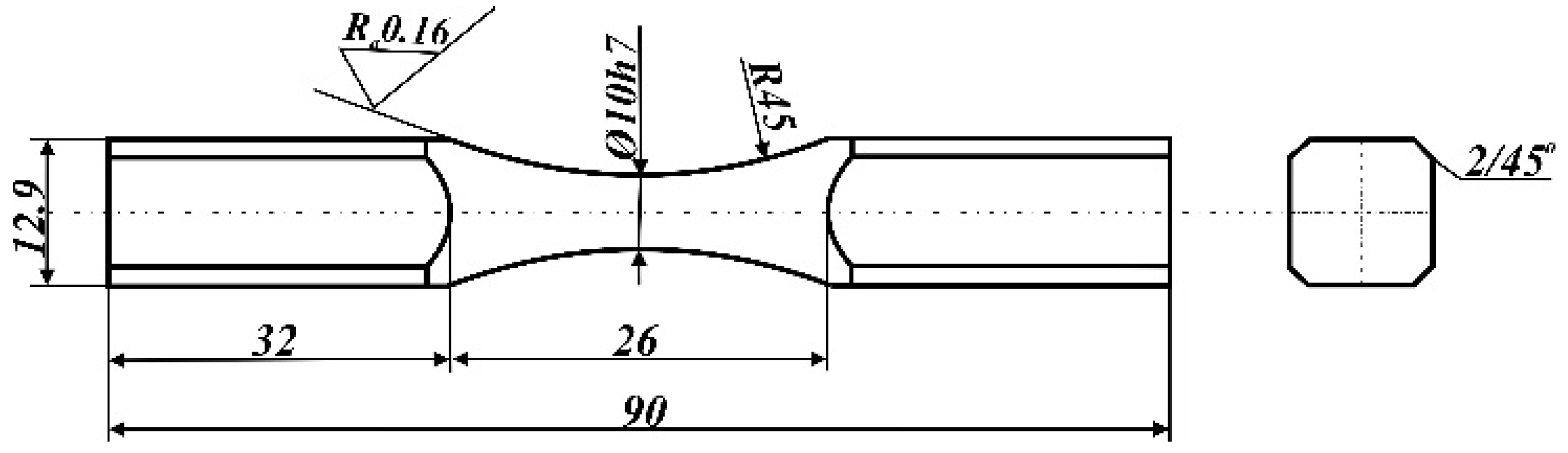
2.2. Fatigue Behavior
2.3. Microstructure Observation
2.4. Fractography
3. Results and Discussion
3.1. Fatigue Properties
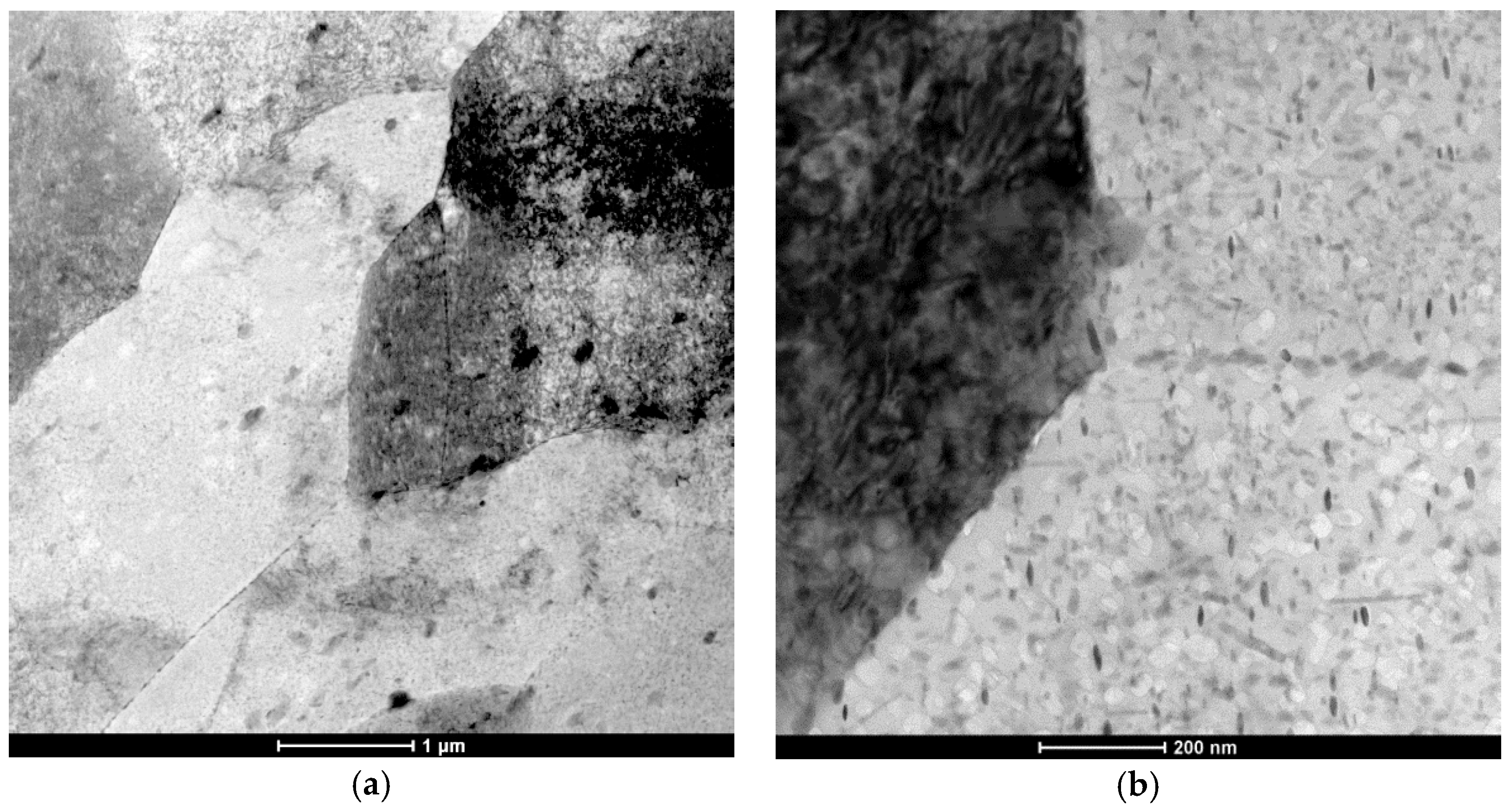
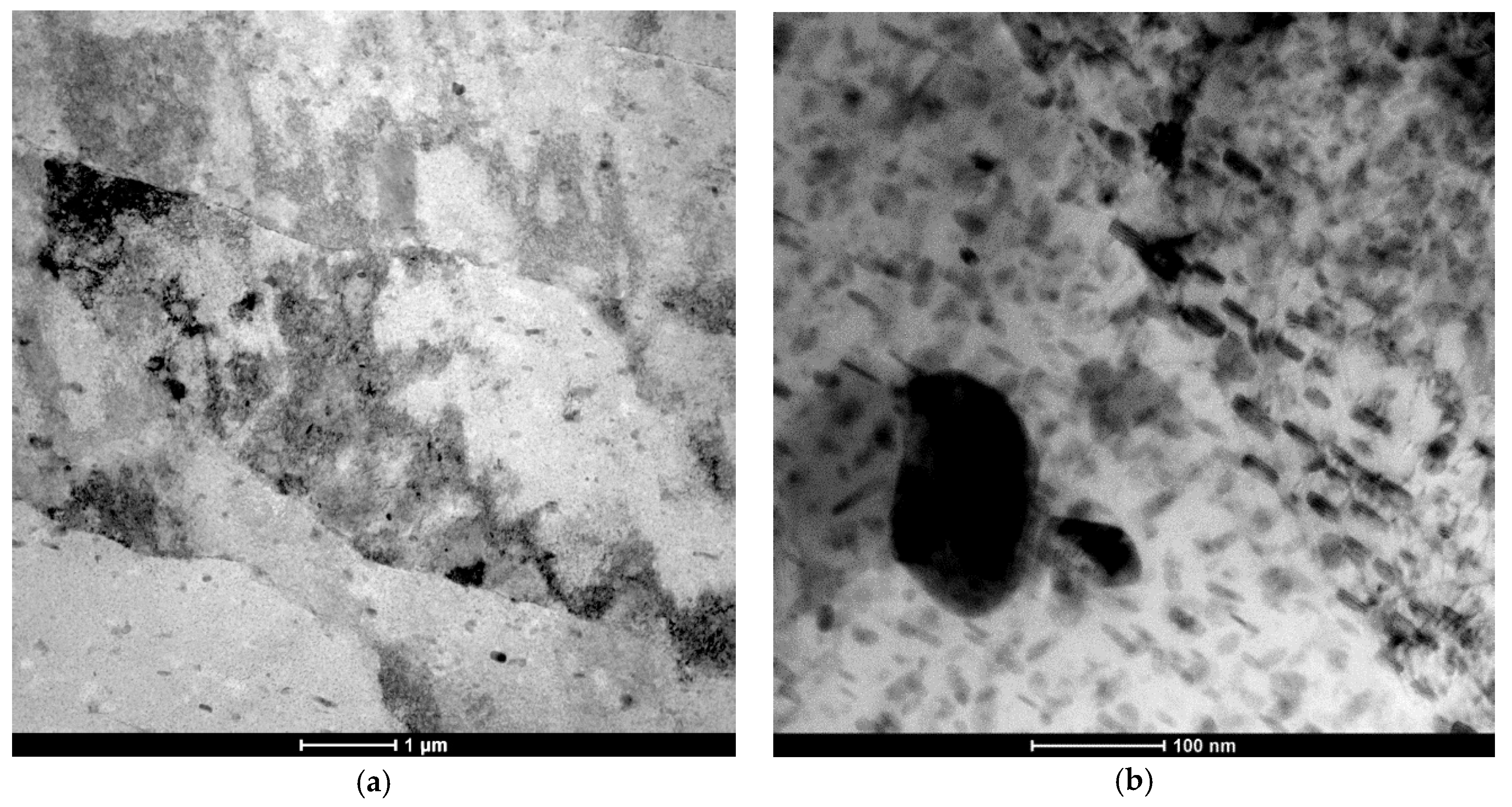
3.2. Microstructure
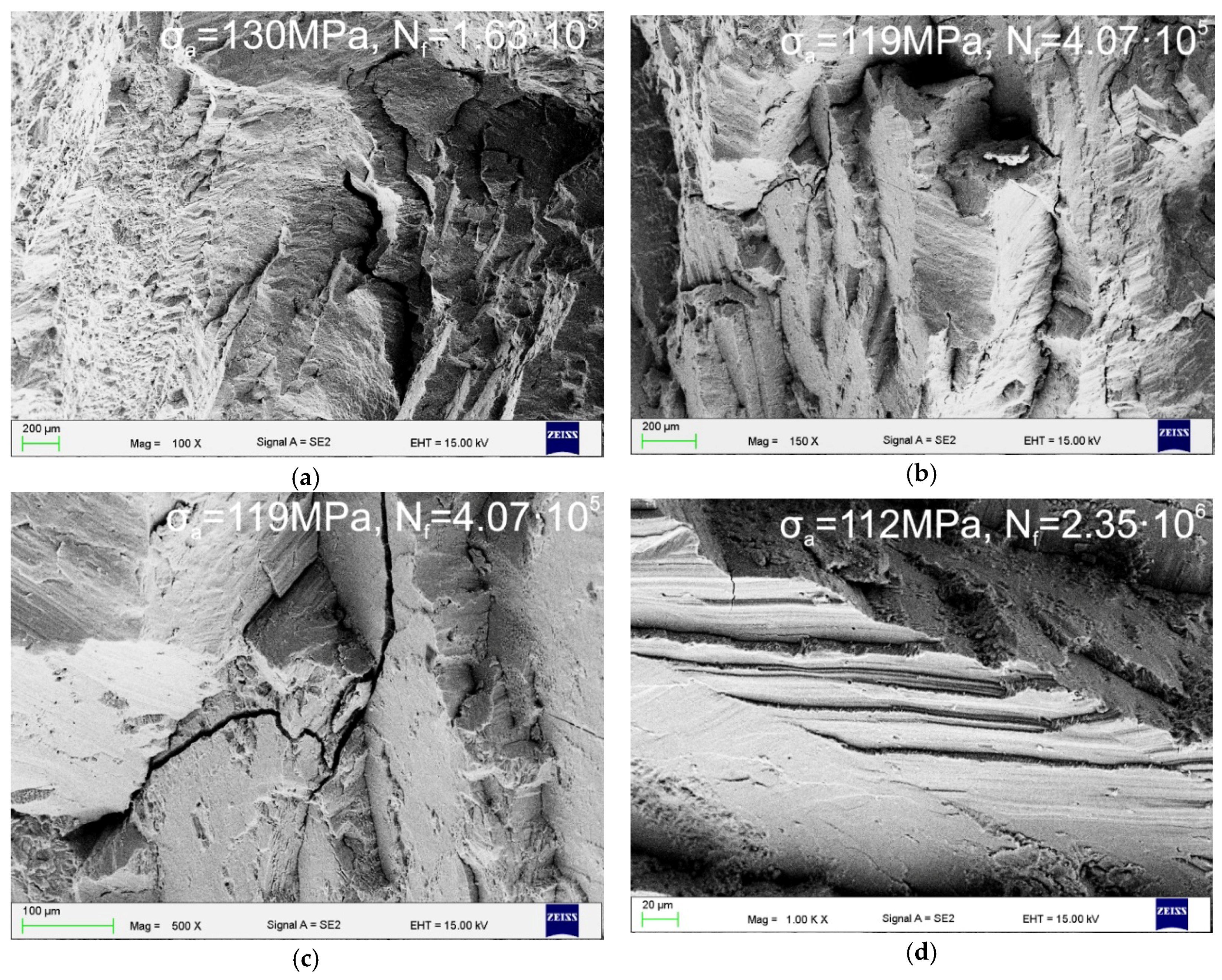
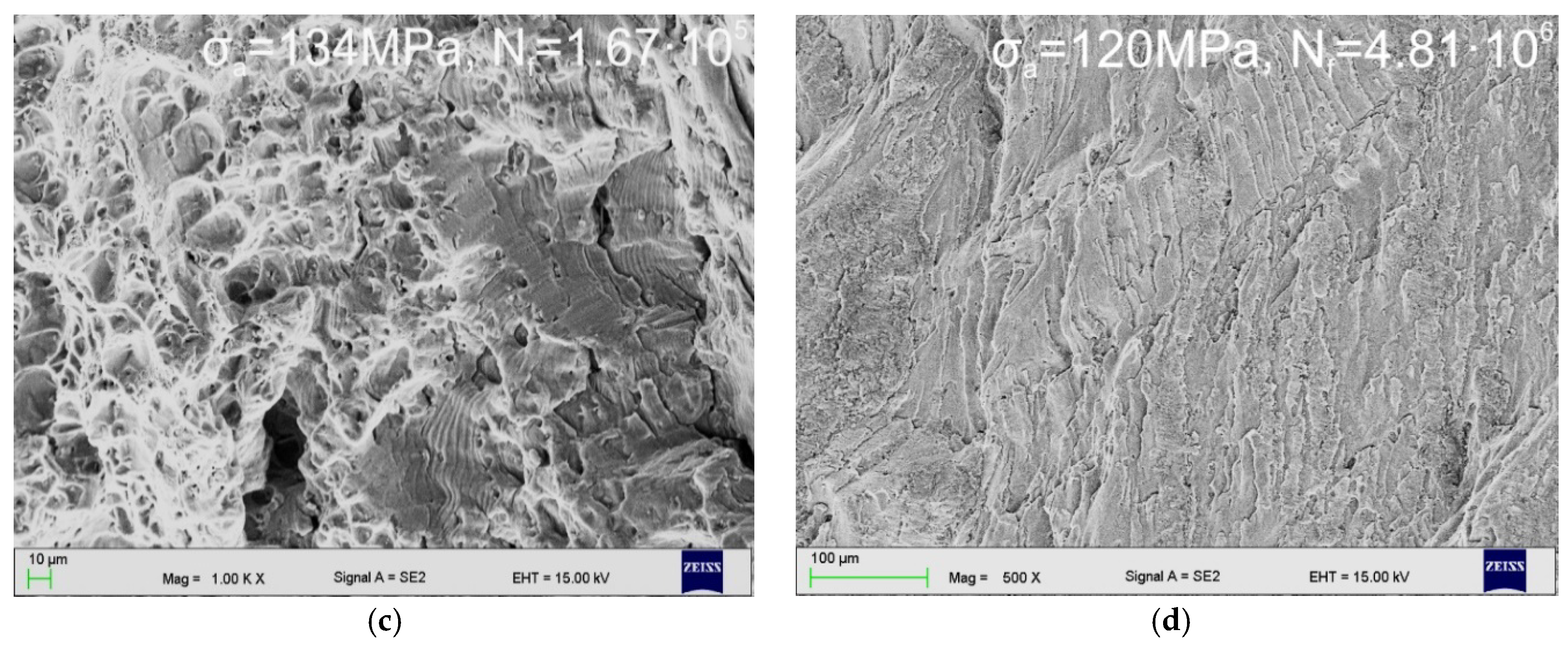
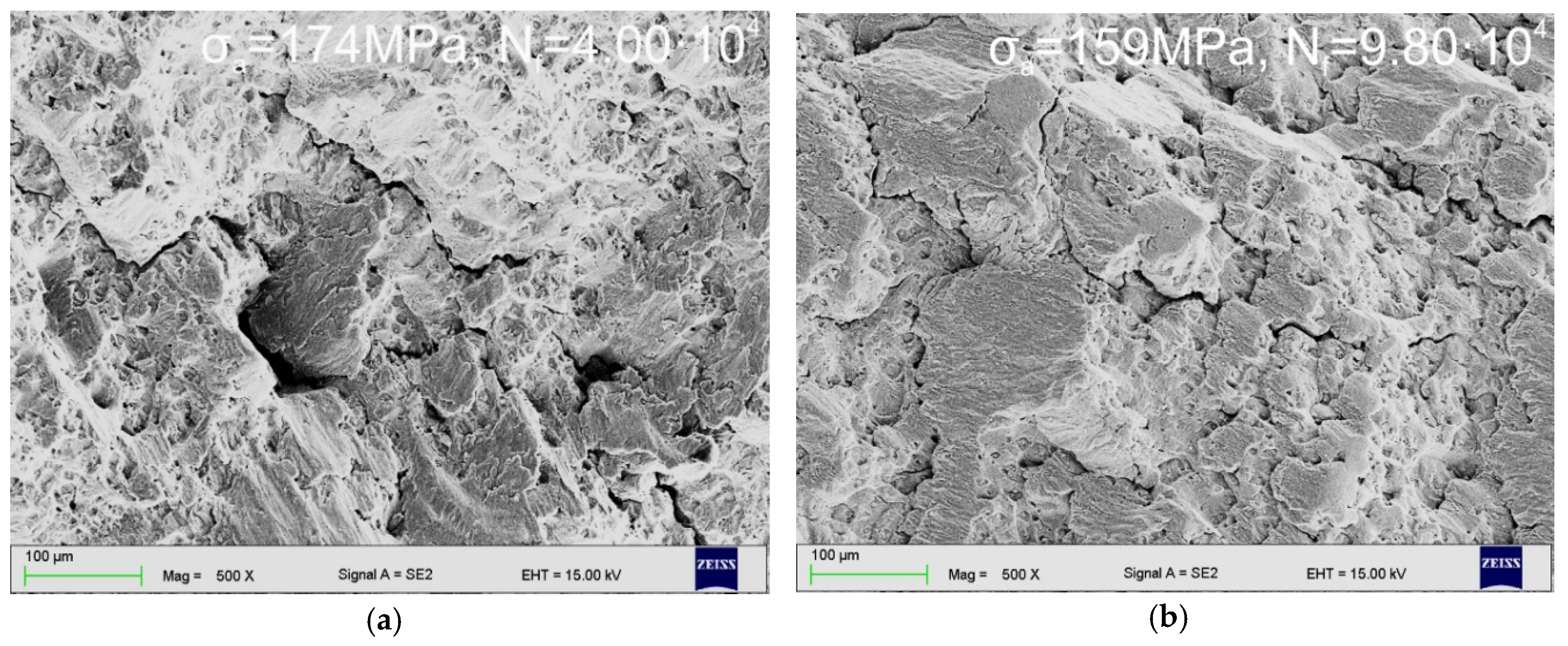
3.3. Fractography
4. Conclusions
- Plastic deformation in the range of 10–30%, realized through cold rolling, leads to an increase of the density of privileged areas for homogeneous precipitation of the strengthening particles. It results in a more pronounced precipitation of η–MgZn2 phase and a decay of precipitation-free zones in the vicinity of grain boundaries.
- The material condition after LTTT and the size of cyclic loads determine the portion of transcrystalline, quasi-cleavage, and ductile fracture. The increase in deformation level in the range of 10–30% results in an increase of the proportion of ductile fracture.
- Grain boundaries are the areas where the initiation of fatigue cracks is easy. Its propagation occurs mainly by the connection of successive cracks, which are formed on adjacent boundaries.
- The morphology and high dispersion of intermetallic η–MgZn2 particles, and the activation of a significant quantity of cross slip systems, are the factors determining the formation of extensive crack paths under conditions of complex bending-torsion fatigue loads.
Author Contributions
Funding
Acknowledgments
Conflicts of Interest
References
- Chemingui, M.; Khitouni, M.; Jozwiak, K.; Mesmacque, G.; Kolsi, A. Characterization of the mechanical properties changes in an Al-Zn-Mg alloy after a two-step ageing treatment at 70 °C and 135 °C. Mater. Des. 2010, 31, 3134–3139. [Google Scholar] [CrossRef]
- Deschamps, A.; Livet, F.; Bréchet, Y. Influence of predeformation on ageing in an Al-Zn-Mg alloy—I. Microstructure evolution and mechanical properties. Acta Mater. 1998, 27, 281–292. [Google Scholar] [CrossRef]
- Lü, X.; Guo, E.; Rometsch, P.; Wang, L. Effect of on-step and two-step homogenization treatments on distribution of Al3Zr dispersoids in commercial AA7150 aluminium alloy. Trans. Nonferr. Met. Soc. China 2012, 22, 2645–2651. [Google Scholar] [CrossRef]
- Thevenet, D.; Mliha-Touati, M.; Zeghloul, A. Characteristics of the propagation deformation bands associated with the Portevin-Le Chatelier effect in an Al-Zn-Mg-Cu alloy. Mater. Sci. Eng. A 2000, 291, 110–117. [Google Scholar] [CrossRef]
- Khalid Rafi, H.; Janaki Ram, G.D.; Phanikumar, G.; Prasad Rao, K. Microstructure and tensile properties of friction welded aluminium alloy AA7075-T6. Mater. Des. 2010, 31, 2375–2380. [Google Scholar] [CrossRef]
- Andreatta, F.; Terryn, H.; de Wit, J.H.W. Corrosion behavior of different tempers of AA7075 aluminium alloy. Electrochim. Acta 2004, 49, 2851–2862. [Google Scholar] [CrossRef]
- Xiao, Y.P.; Pan, Q.L.; Li, W.B.; Liu, X.Y.; He, Y.B. Influence of retrogression and re-aging treatment on corrosion behavior of an Al-Zn-Mg-Cu alloy. Mater. Des. 2011, 32, 2149–2156. [Google Scholar] [CrossRef]
- Gürbüz, R.; Sarioğlu, F. Fatigue crack growth behavior in aluminium alloy 7475 under different aging conditions. Mater. Sci. Technol. 2001, 17, 1539–1543. [Google Scholar] [CrossRef]
- Payne, J.; Welsh, G.; Christ, R.J., Jr.; Nardiello, J.; Papazian, J.M. Observations of fatigue crack initiation in 7075-T651. Int. J. Fatigue 2010, 32, 247–255. [Google Scholar] [CrossRef]
- Das, P.; Jayaganthan, R.; Chowdhury, T.; Singh, I.V. Fatigue behaviour and crack growth rate of cryorolled Al 7075 alloy. Mater. Sci. Eng. A 2011, 528, 7124–7132. [Google Scholar] [CrossRef]
- Jo, B.L.; Park, D.S.; Nam, S.W. Effect of Mn dispersoid on the fatigue crack propagation of Al-Zn-Mg alloys. Metall. Mater. Trans. 1996, 27, 490–493. [Google Scholar] [CrossRef]
- Park, D.S.; Kong, B.O.; Nam, S.W. Effect of Mn-dispersoid on the low-cycle fatigue life of Al-Zn-Mg alloys. Metall. Mater. Trans. 1994, 25, 1547–1550. [Google Scholar] [CrossRef]
- Deng, C.; Wang, H.; Gong, B.; Li, X.; Lei, Z. Effects of microstructural heterogeneity on very high cycle fatigue properties of 7050-T7451 aluminum alloy friction stir butt welds. Int. J. Fatigue 2016, 83, 100–108. [Google Scholar] [CrossRef]
- Kowalski, A.; Ozgowicz, W.; Grajcar, A.; Lech-Grega, M.; Kurek, A. Microstructure and fatigue properties of AlZn6Mg0.8Zr alloy subjected to low-temperature thermomechanical processing. Metals 2017, 7, 488. [Google Scholar] [CrossRef]
- Zhao, T.; Jiang, Y. Fatigue of 7075-T651 aluminum alloy. Int. J. Fatigue 2008, 30, 834–849. [Google Scholar] [CrossRef]
- Kurek, A.; Wachowski, M.; Niesłony, A.; Płocinski, T.; Kurzydłowski, K.J. Fatigue tests and metallographic of explosively cladded steel-titanium bimetal. Arch. Metall. Mater. 2014, 59, 1565–1570. [Google Scholar] [CrossRef]
- Kowalski, A.; Ozgowicz, W.; Jurczak, W.; Grajcar, A.; Boczkal, S.; Żelechowski, J. Microstructure, mechanical properties and corrosion resistance of thermomechanically processed AlZn6Mg0.8Zr alloy. Materials 2018, 11, 570. [Google Scholar] [CrossRef] [PubMed]
- Cai, Y.; Lang, Y.; Cao, L.; Zhang, J. Enhanced grain refinement in AA7050 Al alloy by deformation-induced precipitation. Mater. Sci. Eng. A 2012, 549, 100–104. [Google Scholar] [CrossRef]
- Huo, W.T.; Shi, J.T.; Hou, L.G.; Zhang, J.S. An improved thermo-mechanical treatment of high-strength Al-Zn-Mg-Cu alloy for effective grain refinement and ductility modification. J. Mater. Process. Technol. 2017, 239, 303–3014. [Google Scholar] [CrossRef]
- Wang, W.; Zhang, W.; Wang, H.; Fang, X.; Liang, X. Influence of grain boundary on the fatigue crack growth of 7050-T7451 aluminum alloy based on small time scale method. Adv. Mater. Sci. Eng. 2016. [Google Scholar] [CrossRef]


| Elements | Zn | Mg | Mn | Fe | Cr | Si | Zr | Al |
|---|---|---|---|---|---|---|---|---|
| Mass fraction wt. % | 6.13 | 0.74 | 0.29 | 0.19 | 0.17 | 0.12 | 0.08 | Bal. |
© 2018 by the authors. Licensee MDPI, Basel, Switzerland. This article is an open access article distributed under the terms and conditions of the Creative Commons Attribution (CC BY) license (http://creativecommons.org/licenses/by/4.0/).
Share and Cite
Kowalski, A.; Ozgowicz, W.; Jurczak, W.; Grajcar, A.; Boczkal, S.; Kurek, A. Microstructural and Fractographic Analysis of Plastically Deformed Al-Zn-Mg Alloy Subjected to Combined High-Cycle Bending-Torsion Fatigue. Metals 2018, 8, 487. https://doi.org/10.3390/met8070487
Kowalski A, Ozgowicz W, Jurczak W, Grajcar A, Boczkal S, Kurek A. Microstructural and Fractographic Analysis of Plastically Deformed Al-Zn-Mg Alloy Subjected to Combined High-Cycle Bending-Torsion Fatigue. Metals. 2018; 8(7):487. https://doi.org/10.3390/met8070487
Chicago/Turabian StyleKowalski, Aleksander, Wojciech Ozgowicz, Wojciech Jurczak, Adam Grajcar, Sonia Boczkal, and Andrzej Kurek. 2018. "Microstructural and Fractographic Analysis of Plastically Deformed Al-Zn-Mg Alloy Subjected to Combined High-Cycle Bending-Torsion Fatigue" Metals 8, no. 7: 487. https://doi.org/10.3390/met8070487