Effect of Tool Rotational Speeds on the Microstructure and Mechanical Properties of a Dissimilar Friction-Stir-Welded CuCrZr/CuNiCrSi Butt Joint

1
State Key Laboratory of High Performance Complex Manufacturing, Central South University, Changsha 410083, China
2
Light Alloy Research Institute, Central South University, Changsha 410083, China
*
Author to whom correspondence should be addressed.
Metals 2018, 8(7), 526; https://doi.org/10.3390/met8070526
Submission received: 1 June 2018
/
Revised: 4 July 2018
/
Accepted: 4 July 2018
/
Published: 6 July 2018
(This article belongs to the Special Issue Friction Stir Welding and Processing in Alloy Manufacturing)
Abstract
:In this study, dissimilar CuNiCrSi and CuCrZr butt joints were friction stir welded at a constant welding speed of 150 mm/min, but at different rotational speeds of 800, 1100, 1400, 1700, and 2100 rpm. Sound joints were achieved at the rotational speeds of 1400 and 1700 rpm. It was found that the area of retreating material and grain size in the nugget zone increased with the increase of tool rotational speeds. The base metal on the CuNiCrSi side (CuNiCrSi-BM) contains a large density of Cr and δ-Ni2Si precipitates, and a great deal of Cr precipitates can be observed in the base metal on the CuCrZr side (CuCrZr-BM). All these precipitates are completely dissolved into the matrix in both the nugget zone on the CuCrZr side (CuCrZr-NZ) and the nugget zone on the CuNiCrSi side (CuNiCrSi-NZ). The precipitation strengthening plays a dominant role in the base metals, but the grain boundary strengthening is more effective in improving the mechanical properties in the nugget zone. Both the hardness and tensile strength decrease sharply from the base metal to the nugget zone due to the dissolution of precipitates. Mechanical properties such as microhardness and tensile strength in the nugget zone decrease with the increase of rotational speeds because the grain size is larger at a higher rotational speed.
1. Introduction
Friction-stir welding (FSW) is a solid-state joining process [1]. This technique is characterized by combining frictional heating and mechanical breakup arising from the rotating tool. Friction-stir welding was initially designed to weld aluminum alloys. However, with the improvement of this technique, FSW has been significantly expanded to the welding of high-melting-point materials, such as Cu and its alloys. The friction-stir-welded joints are controlled by several welding parameters. The tool rotational speed and the welding speed are two dominant welding parameters. Numerous studies have been carried out to study the influence of the tool rotational speed and the welding speed on the resulting properties of copper joints. Sun et al. [2] studied the microstructure and mechanical properties of FSW copper joints over a wide range of welding parameters, including rotational speed (from 750 to 1200 rpm) and welding speed (from 200 to 800 mm/min). They found that the grain size in the nugget zone (NZ) is much smaller than that of the base metal, and the highest tensile strength of joints can reach 380 MPa. Liu et al. [3] reported friction-stir-welded copper joints at different tool rotational speeds ranging from 300 to 1000 rpm. They found that the ultimate tensile strength (UTS) initially increased to the maximum (277 MPa) and then decreased as the rotational speeds increased from 300 to 1000 rpm. Azizi et al. [4] reported microstructure and mechanical properties of friction-stir-welded copper joints in plates with 10 mm thickness. They found that the ultimate tensile strength initially increases to a maximum (260 MPa) and then decreases when the welding speeds increase from 50 to 200 mm/min.
Dissimilar joints are currently of great interest in industrial applications due to their technical and economic benefits [5]. Copper and aluminum are the most common materials used in the dissimilar joints. Dissimilar joints of Al/Cu which combine copper’s improved strength and electrical properties with aluminum’s low weight are used widely in industrial fields. There are a number of studies which are related to dissimilar Al/Cu joints. Xue et al. [6] investigated the effects of the rotational speeds and tool offsets on dissimilar friction-stir-welded joints of 1060 aluminum and pure copper. They found that good tensile properties can be obtained at higher rotational speeds of 600–1000 rpm with a constant welding speed of 100 mm/min, as well as proper pin offsets of 2 and 2.5 mm to softer aluminium alloys. The maximum value of tensile strength in their study was 110 MPa. Tan et al. [7] discussed the microstructure and mechanical properties of dissimilar 5A02 aluminium and pure copper joints fabricated by FSW. They found that defect-free joints can be achieved under the condition of high rotational speeds (1100 rpm) and low welding speed (20 mm/min), with the tool offset by 0.2 mm relative to the weld centreline and Al sheet. They also found that sound joints can be obtained when the harder copper plate was fixed at the retreating side. Sahu et al. [8] systematically investigated the influence of welding parameters, including plate position, tool offsets, and tool rotational speeds, on the microstructure and mechanical properties of dissimilar 1051 aluminium and pure copper joints. They found that good mechanical properties can be obtained at a tool rotational speed of 1200 rpm, welding speed of 30 mm/min, 0.1 mm plunging depth, and 1.5 mm offset towards Al alloy. In this condition, the ultimate strength and the yield strength can respectively reach 126 MPa and 119.3 MPa.
Thus, the review of the existing literature exposes the substantial study on FSW of Cu and dissimilar Al/Cu joints. However, the conventional Cu joints and dissimilar Al/Cu joints possess limited capabilities to handle structural loads due to their relatively lower strength. It is also difficult for Al/Cu dissimilar joints to perform well in terms of electrical conductivity. The conventional Cu joints and dissimilar Al/Cu joints cannot fulfill the demands of critical functional and structural applications, which require both a high mechanical strength and a high electrical conductivity. CuCrZr and CuNiCrSi alloys, which are treated by solution and aging process, can possess a good combination of high strength and good electrical conductivities. The ultimate tensile strength and the electrical conductivity of the CuCrZr alloy can reach about 530 MPa and 80% international annealed copper standard (IACS) [9], respectively. In comparison with the CuCrZr alloy, the CuNiCrSi alloy possesses a higher ultimate tensile strength of 600–800 MPa, but a lower electrical conductivity of about 45% IACs, owing to the different additions of Ni and Si [10]. CuCrZr and CuNiCrSi alloys with both high strength and good electrical conductivity are in high demand in many industries, in such applications as large generator rotors and heat sink material for fusion reactor components [11,12]. Therefore, fabrication and processing technology of these alloys with both high strength and high conductivity are very important. Although substantial studies have been focused on the FSW of conventional copper alloys and dissimilar Al/Cu alloys, the reports concentrating on FSW of copper alloys with high strength and good electrical conductivity such as CuCrZr and CuNiCrSi alloys are limited. There are only a few studies on the FSW of CuCrZr. Sahlot et al. [13] discussed the wear of the tool used in the FSW of CuCrZr rather than characteristics of the joints. Jha et al. [14] studied the microstructure and mechanical properties of CuCrZr alloys welded by FSW. They found that the tensile strength of welded joints was lower than that of the base metal due to the dissolution of precipitates in the welded zone. Lai et al. [15] studied the microstructural properties of the CuCrZr joints welded by FSW. The thickness of CuCrZr plates in their study were 10 mm. They found that the grain size in the NZ was decreased gradually from the top to the bottom area of the welds due to the distinctive heat production and the heat dissipation on the welding joint, which cause the microhardness and tensile strength of the welds to be slightly increased from the top to the bottom area of the welds. To our knowledge, no studies have evaluated the effects of welding parameters on the properties of dissimilar CuCrZr and CuNiCrSi joints fabricated by FSW. The present study systematically investigated the influence of tool rotational speeds on the microstructural evolution and mechanical properties of dissimilar CuCrZr and CuNiCrSi joints. The grain structure and precipitates of the investigated alloys after the FSW process were discussed in detail. The mechanical properties including microhardness and tensile strength were also studied in detail.
2. Materials and Methods
The base materials used in this study were rolled CuCrZr and CuNiCrSi plates with 3 mm thickness. All plates were cut into dimensions of 300 mm long and 100 mm wide before the welding process. The CuCrZr alloy was treated through solution (920 °C for 0.5 h) process and then aged at 440 °C for 2 h. The CuNiCrSi alloy was also subjected to solution (800 °C for 2 h) treatment followed by an aging (450 °C for 5 h) process. Table 1 shows the chemical compositions of these two alloys.
2.1. Friction-Stir-Welding Process
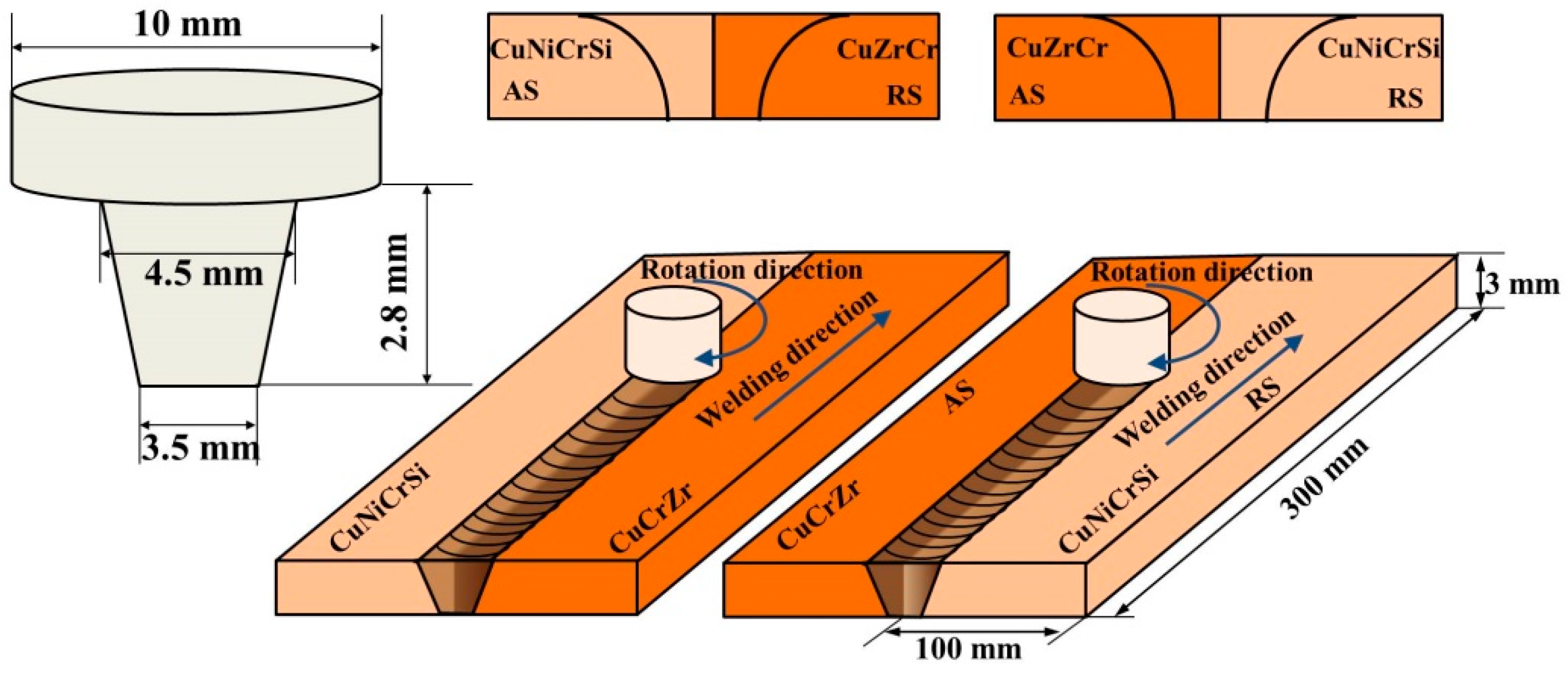
Dissimilar CuCrZr and CuNiCrSi joints were friction-stir-welded by a tool at rotational speeds of 800, 1100, 1400, 1700, and 2000 rpm. The tool welding speed and the tool tilt angle were fixed at 150 mm/min and 2.5°, respectively. To investigate the effects of material positions on microstructure and mechanical properties, the CuCrZr and CuNiCrSi alloys were alternately placed on the advancing side (AS) and retreating side (RS), respectively. When CuNiCrSi was on the AS, then CuZrCr was on the retreating side (RS) of the welding tool pin. When CuZrCr was on the AS, then CuNiCrSi was on the RS. The detailed welding conditions are listed in Table 2. The friction-stir-welding process was performed on a specially constructed apparatus, which has been reported by our previous work [16]. The FSW tool was composed of a concave shoulder and a conical pin. The diameters of the shoulder and the length of the pin were 10 mm and 2.8 mm, respectively. The diameters of the pin were 3.5 mm at the root and 4.5 mm at the head. For the welding process, the tool rotated in the clockwise direction. The pin was slowly inserted into the workpieces with a constant plunging depth of 0.1 mm and plunging speed of 0.05 mm/s. The schematic presentation of the friction-stir-welding process and dimensions of the FSW tool are shown in Figure 1.
After the welding, a preliminary region of applicable rotational speeds was carefully chosen by eliminating joints which had groove-like defects and surface-galling defects on the surfaces of the joints. Then, X-ray radiography inspections were performed on an X-ray nondestructive testing system (XD7600NT, Dage, London, UK) to further reveal the weld defects in the inner zones of the welded joints. The welded joints were scanned along the weld line using a 100 KV X-ray source voltage. Finally, joints were cut into strips perpendicularly to the welding line. Specimens for metallographic observation and mechanical testing were made from these strips.
2.2. Microstructural Characterization
The microstructures of samples under welding conditions were analyzed by optical microscope (OM), electron backscatter diffraction (EBSD), and transmission electron microscope (TEM). Specimens for OM analysis were polished according to a standard process and then etched with a 40 mL H2O, 10 mL HCl, and 2 g Fe3Cl solution. The transverse cross-section macrographs of the welded joints were observed by a 3D microscope (VHX 5000, KEYENCE, Osaka, Japan). For the EBSD analysis, the samples after mechanical polishing were further vibration-polished to remove stress. The grain structures of different zones including CuCrZr-BM, CuCrZr-NZ, CuNiCrSi-BM, and CuNiCrSi-NZ were analyzed using a FEI Quanta 650 FEG scanning electron microscopy (FEI Corporation, Hillsboro, OR, USA). For the TEM study, some thin foils of 0.5 mm thickness were cut perpendicular to the welding direction. Then, the foils were grinded into one of a thickness of 70 µm~80 µm and several (Φ3 mm) discs were punched out from different zones including the CuCrZr-BM, CuCrZr-NZ, CuNiCrSi-BM, and CuNiCrSi-NZ. A twin-jet electro-polisher was used to produce electron-transparent thin sections in these discs with a solution of 75% methanol and 25% nitric acid, using an electrolyte voltage of 10 V at −30 °C. TEM experiments were conducted on the Tecnai G2 F20 (FEI Corporation, Hillsboro, OR, USA) with an acceleration voltage of 120 keV.
2.3. Mechanical Testing
The tensile properties of the dissimilar joints were evaluated using a universal electronic tensile testing machine (MTS Systems Corporation, Eden Prairie, MN, USA). The tensile testing specimens with a gauge length of 150 mm and a width of 25 mm were machined perpendicularly to the welding direction using a wire electrical discharge machine (DK7720, Terui, Taizhou, China). The tensile tests were performed three times for each welding condition with a testing speed of 2 mm/min at room temperature. The measurement of Vickers hardness was conducted along the centerline, using a Vickers hardness machine (Huayin Testing Instrument Co., Ltd., Yantai, China) with a load of 100 g and a dwell time of 10 s. The distance between each neighboring measured points was 0.5 mm. The Vickers hardness tests were repeated three times under each welding condition to obtain the average microhardness of welds.
3. Results
3.1. Surface Morphologies and X-ray Radiographs of the Joints
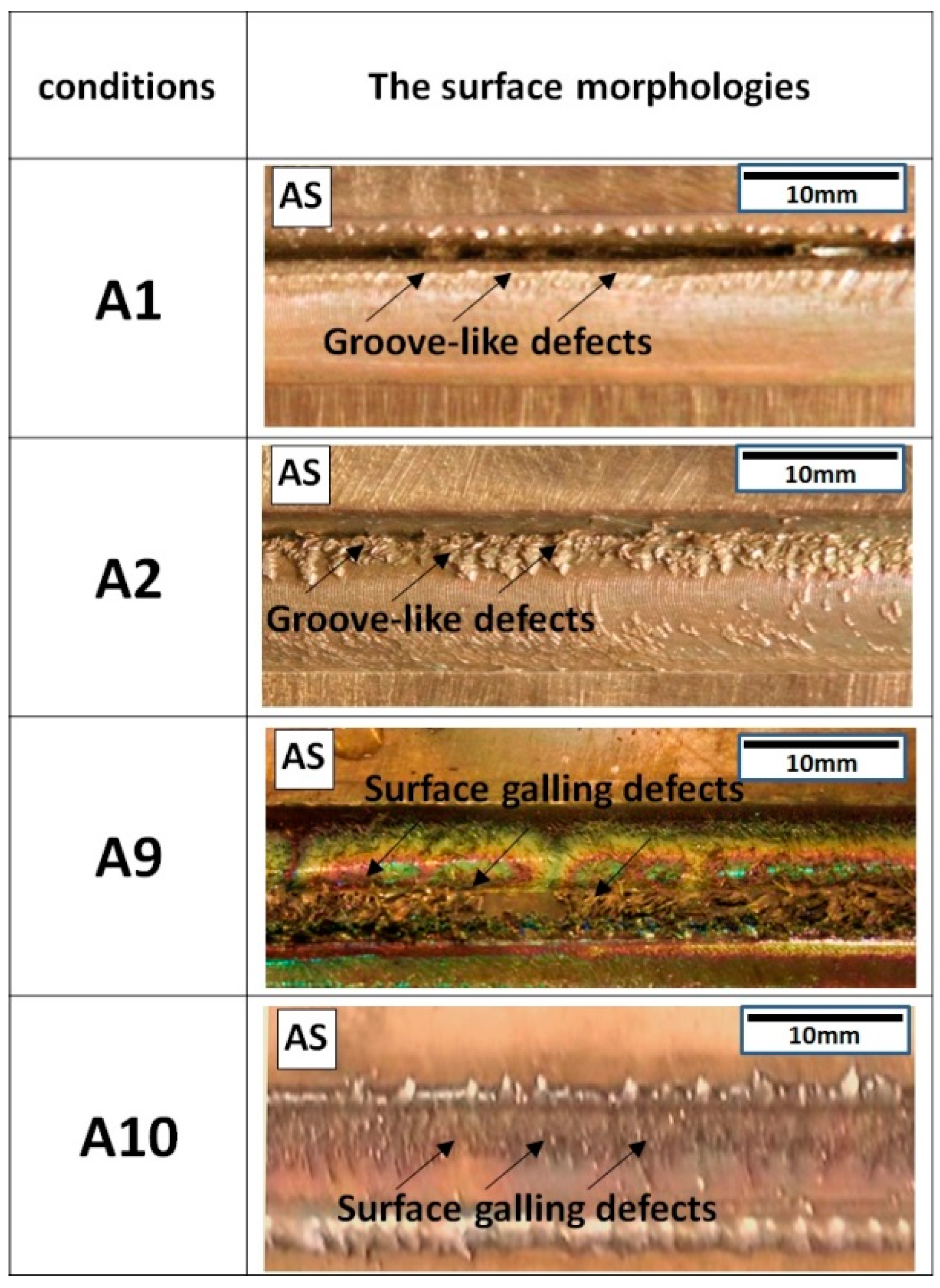
Figure 2 shows the surface morphologies of dissimilar CuCrZr/CuNiCrSi butt joints under conditions A1, A2, A9, and A10. It is seen that the groove-like defects are formed on the AS side at the lower rotational speeds of 800 rpm. However, surface galling defects are seen to occur at the higher rotational speed of 2000 rpm.
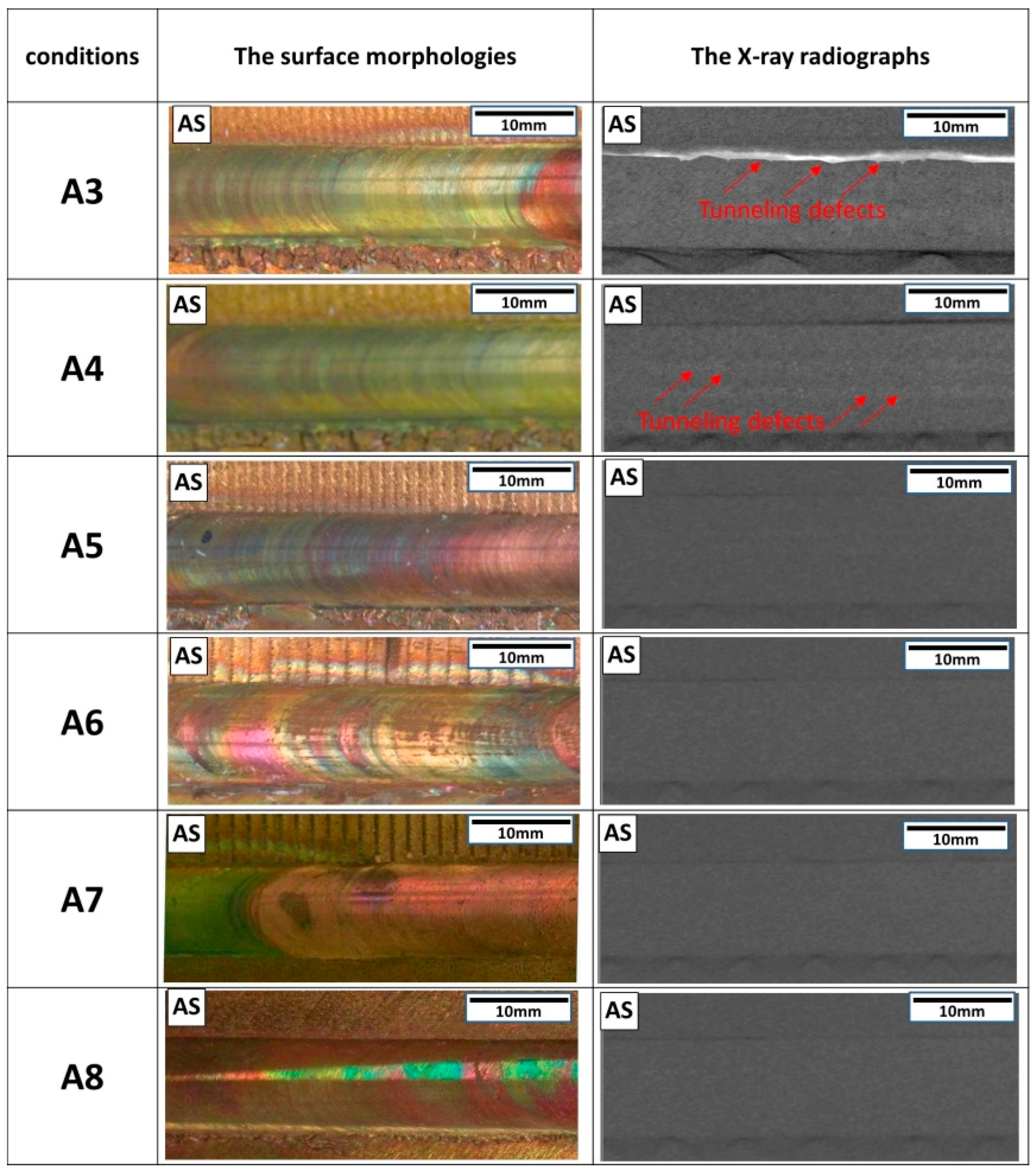
Figure 3 shows the surface morphologies and the relevant X-ray radiographs of welded joints under conditions A3–A8. When the rotational speed is 1100 rpm, tunnelling defects are found to be formed inside the joints by X-ray radiographs, but these defects cannot be seen on the surface morphologies. The defect-free joints are formed at the rotational speeds of 1400 rpm and 1700 rpm. Based on the surface morphologies and X-ray radiographs of the stir zone, it can be concluded that the rotational speeds of 1400 rpm and 1700 rpm are adequate rotational speeds for dissimilar friction-stir-welded CuCrZr/CuNiCrSi butt joints at the constant travel speed of 150 mm/min.
3.2. Microstructure of Dissimilar CuCrZr/CuNiCrSi Butt Joints
Figure 4 shows the transverse cross-section macrographs of the welded joints obtained under conditions A3–A8. Due to the difference in etching response, the CuNiCrSi alloy appears as a light color, whereas the CuCrZr alloy appears as the dark colour regions. When the rotational speed is 1100 rpm, a tunnelling defect is formed at the bottom of the AS side with the CuNiCrSi alloy located on the AS, while two smaller defects are observed in the NZ near the AS with the inverse material positions. Sound joints are produced at the rotational speeds of 1400 and 1700 rpm. The cross-section micrographs are in complete conformity with the X-ray radiographs seen in Figure 3. Some discernable differences can be found between these cross-section macrographs. Two stir patterns can be identified from these differences: one is that the area of retreating materials in the NZ increases with the increase of rotational speeds; the other is that the area of retreating materials in the NZ is seen to be a little bigger when the CuNiCrSi alloy is placed on the RS.
Figure 5 shows inverse pole figure maps in the different regions, including the CuCrZr-BM, CuNiCrSi-BM, CuCrZr-NZ, and CuNiCrSi-NZ. The grain size frequencies of different zones under different rotational speeds of 1400 and 1700 rpm are also shown in Figure 6. Figure 5a,b shows that both the CuNiCrSi-BM and CuCrZr-BM exhibit a rolled structure with coarse grains of different size. It can be found from Figure 6a,b that the average grain sizes of the CuNiCrSi-BM and CuCrZr-BM are 33.30 µm and 40.53 µm, respectively. In comparison, the CuNiCrSi-NZ (Figure 5c,e) and the CuCrZr-NZ (Figure 5d,f) are composed of equiaxed grains with even distribution. Moreover, the grain size in the NZ is observed to increase with the increase of rotational speeds. The average grain sizes of the CuNiCrSi-NZ and CuCrZr-NZ are 0.95 µm (Figure 6c) and 1.42 µm (Figure 6d) at the rotational speed of 1400 rpm, respectively. However, the average grain sizes of the CuNiCrSi-NZ and CuCrZr-NZ increase to 1.48 µm (Figure 6e) and 2.32 µm (Figure 6f) with the rotational speed increased to 1700 rpm.
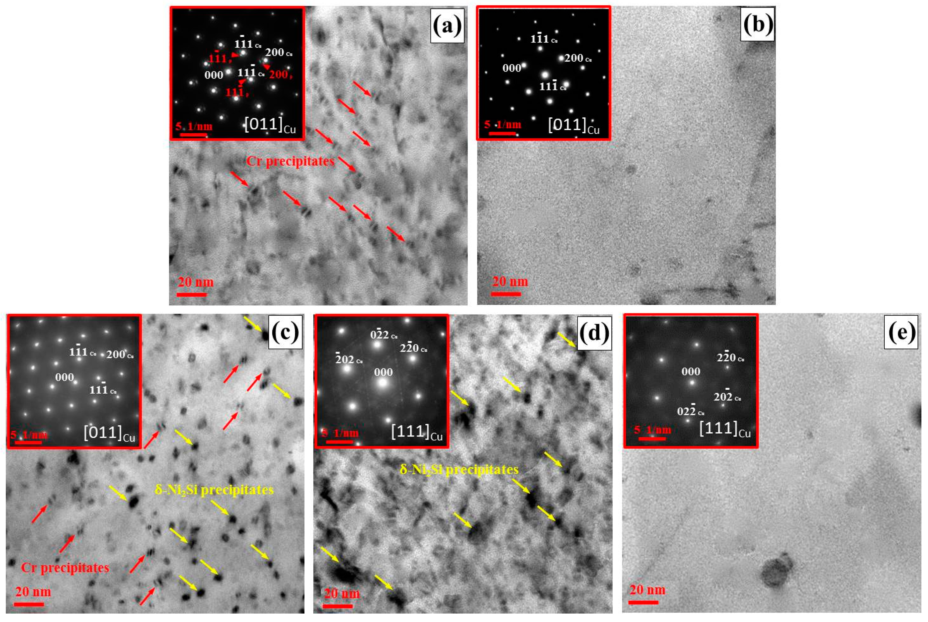
Figure 7 shows the bright-field TEM micrographs of samples from different zones at the rotational speed of 1400 rpm (condition A5). The relevant selected-area electron diffraction (SAD) patterns are shown in the top left-hand corner of each TEM micrograph as well. Figure 7a shows that the lobe-lobe contrast precipitates are scattered randomly in the CuCrZr-BM. The average length of these precipitates is 5–8 nm. In addition, the relevant SAD pattern parallel to the [011]Cu direction reveals the reflections spots from the Cu matrix and precipitates. Moreover, the face center cubic (FCC) Cr precipitates can be identified as the contributors to the reflections spots of the precipitates. In fact, these Cr precipitates are found to be generated in the aging process of the CuCrZr alloy due to the solubility limit of the Cr element in copper [17], and these Cr precipitates can mitigate the movement of dislocations so as to improve the strengths of the CuCrZr alloy. Figure 7c shows that the lobe-lobe contrast Cr precipitates can also be detected in the CuNiCrSi-BM. However, these Cr precipitates cannot be identified by the reflection spots from the relevant SAD pattern parallel to [011]Cu. Apart from Cr precipitates, another type of precipitates which are rod-shaped in the [011]Cu direction (Figure 7c) and disc-shaped in the [111]Cu direction (Figure 7d) can be found in the CuNiCrSi-BM. Moreover, the corresponding SAD patterns parallel to the [011]Cu direction and the [111]Cu direction supported the assumption that the δ-Ni2Si precipitates existed in the CuNiCrSi alloy. Similar results can also be found in previous works about the CuNiCrSi alloy [18,19]. After the welding, Figure 7b,e shows that all precipitates are dissolved into the matrix in both the CuCrZr-NZ and CuNiCrSi-NZ.
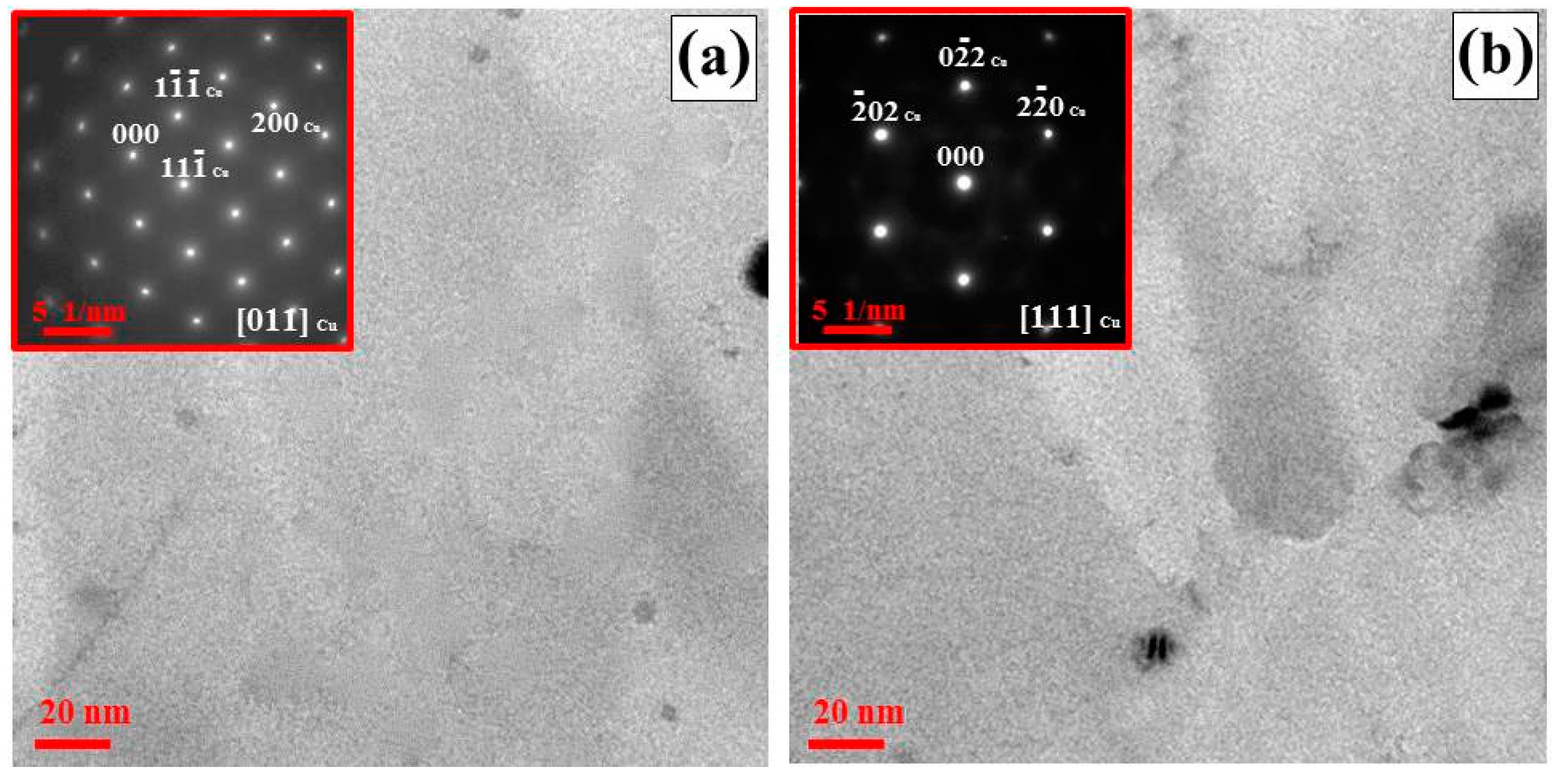
Figure 8 shows the TEM micrographs of samples from the CuCrZr-NZ and CuNiCrSi-NZ when the rotational speed increased to 1700 rpm (condition A7). As shown in Figure 7a,b, all precipitates are dissolved into the Cu matrix in the NZ, which is similar to the results under the rotational speed of 1400 rpm.
3.3. Mechanical Properties of CuCrZr/CuNiCrSi Butt Joints
Figure 9 illustrates the microhardness along the centreline of dissimilar CuCrZr/CuNiCrSi joints produced under different rotational speeds (conditions A5–A8). The distribution of the microhardness profile is asymmetrical along the measuring line, which is caused by different mechanical properties of the CuCrZr and CuNiCrSi alloys. The CuNiCrSi-BM and CuCrZr-BM demonstrate average microhardness values of about 225 HV and 155 HV, respectively. However, both the CuNiCrSi-NZ and CuCrZr-NZ show lower hardness relative to the base metal. The average microhardness in the CuNiCrSi-NZ and CuCrZr-NZ is 150 HV and 125 HV, respectively. The CuCrZr-NZ is the softest region of the whole dissimilar joint. In addition, it can be seen from Figure 9 that the microhardness of the NZ decreases with the increase of rotational speeds.
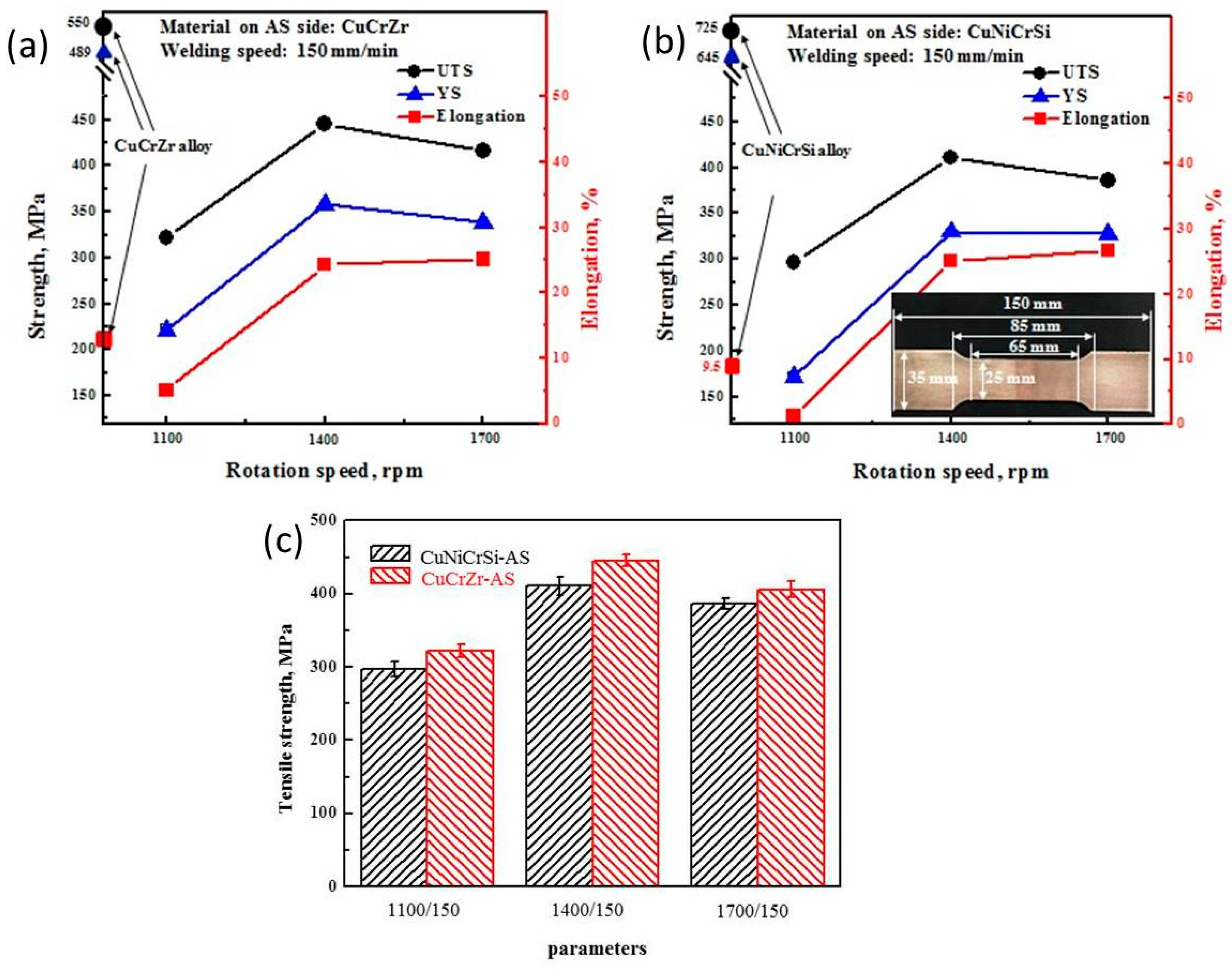
Figure 10 demonstrates the mechanical properties of dissimilar joints. Table 3 describes the ultimate tensile strength, yield strength, and elongation of different joints in detail. Figure 10a shows the variation tendency of mechanical properties when the CuCrZr alloy is located on the AS. It is seen that both the tensile strength and the yield strength tend to increase first and then decrease slightly as the rotational speeds increase from 1100 rpm to 1700 rpm. Figure 10b shows that the same variation tendency is achieved in dissimilar joints when the CuNiCrSi alloy is located on the AS. Figure 10c shows that the strengths of welds are affected by the material position at the same rotational speed. The tensile strength of joints with CuCrZr located on the AS is slightly greater than when CuCrZr is on the RS. The maximum value of tensile strength is about 445 MPa in all welds, which is found to be only 80% and 60% of the tensile strengths of the CuCrZr and CuNiCrSi alloys, respectively. However, the strength of the joints obtained in the present study is still higher than that of most friction-stir-welded copper joints mentioned in previous studies [4,15].
Figure 11 shows the failure locations of tensile testing specimens under the different conditions A3–A8. Obviously, all the welds failed at the stir zone in spite of different rotational speeds. The tensile specimens failed directly at the position of tunnelling defects with no necking under conditions A3 and A4. In comparison, other welds without any defects exhibit some apparent necking in the process of tensile testing. It is worth noting that the relative material position exerts an influence on the failure locations of the tensile specimens, although the previous studies of dissimilar joints always ignored this issue. Specifically, it is seen that the fracture location of the tensile specimens is the CuCrZr-NZ with the CuNiCrSi alloy on the AS (conditions A5 and A7), but the tensile specimens failed at the mixed zone containing the CuNiCrSi and CuCrZr alloys when the CuNiCrSi-NZ and CuCrZr-NZ are in the inverse material position (conditions A6 and A8).
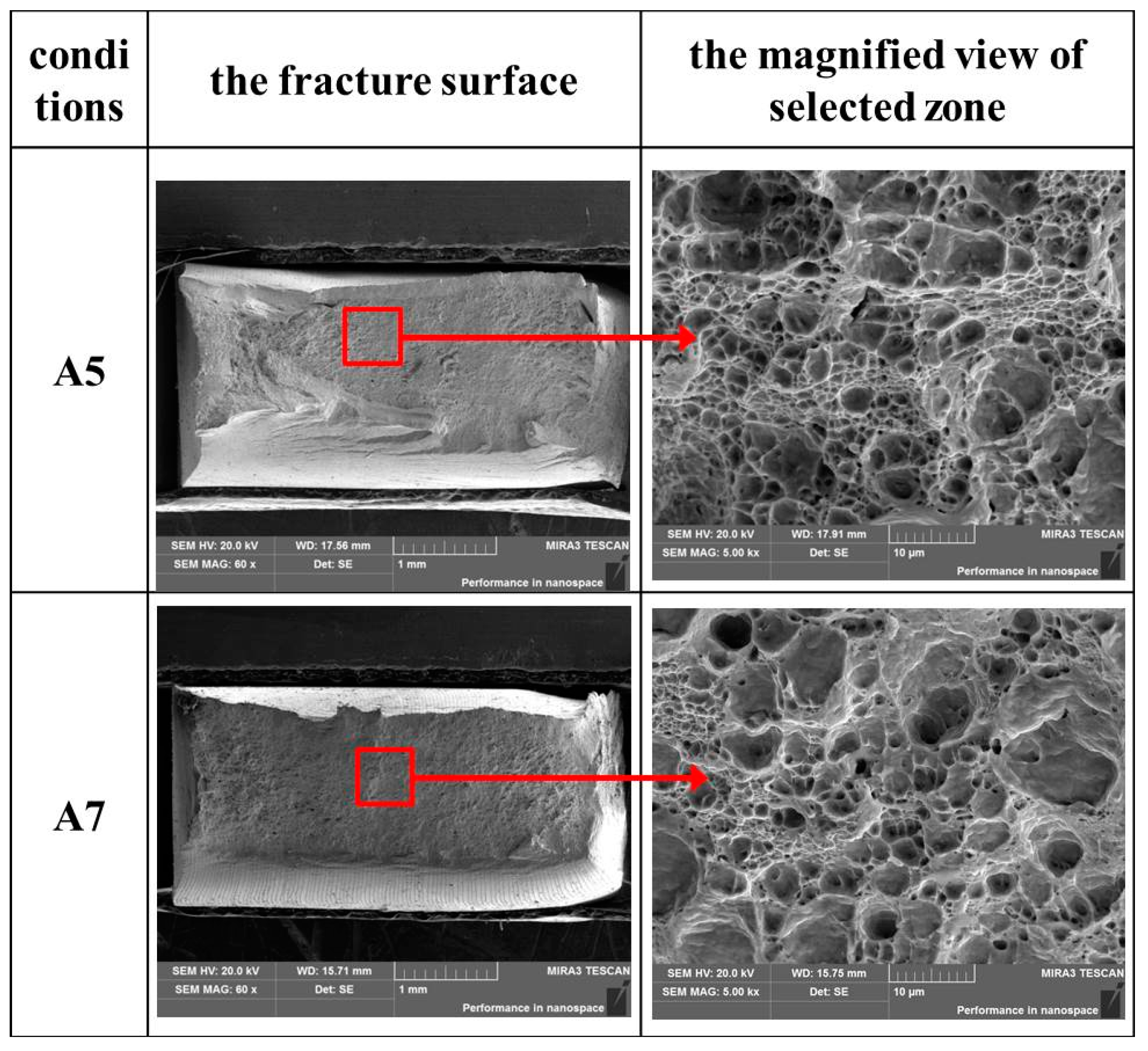
Figure 12 shows the SEM micrographs of the fracture surface of the dissimilar joints under conditions A5 and A7, respectively. Fine populated dimples were observed on fracture surfaces of joints under conditions A5 and A7, which indicates that the failure mode is ductile fracture in these two conditions. There is seen to be no significant difference in the fracture mechanism under conditions A5 and A7. Both selected samples of tensile testing specimens experience extensive plastic deformation during the process of failure in these two conditions.
4. Discussion
4.1. Effect of Rotational Speeds on the Formation of Welds
In Figure 2 and Figure 3, it can be seen that tunneling defects and groove-like defects occur at lower rotational speeds, while higher rotational speed produces galling defects on the surface of joints. The difference between the tunnelling defects and groove-like defects is that tunnelling defects cannot be found on the surface of joints. It is well documented that the heat input resulting from the rotational tool is the key factor in the formation of defects during FSW. The rotational speed has a direct relationship with heat input. According to Equation (1) [20], the maximum temperature during FSW increases with the increase of tool rotational speeds when at a constant tool welding speed. When at the lower rotational speeds of 800 rpm and 1100 rpm, the induced heat is insufficient, which results in less material softening and low plastic flow [21]. Therefore, the groove-like defects and tunnelling defects take place in these conditions. Ajri and Shin [22] offered a numerical model whereby to predict the formation of defects during FSW. The tunnelling defects are formed under the condition that the pin-induced flow does not drive the material on the AS to the RS, while the shoulder-induced flow does. In contrast, groove-like defects occurred when both the shoulder- and pin-induced flow fail to move the material from the advancing side to retreating side. Therefore, tunnelling defects are not visible on the top surface, but are present at the bottom of the joints. The results of the present study are highly consistent with this numerical modelling. However, when the rotational speed increases to 2100 rpm, the surface of the joint appears to contain surface galling as a result of too much heat input during the FSW [23].
where T is the welding temperature (°C), Tm is the melting temperature of the plates (°C), 0.04 < α < 0.06 and 0.65 < K < 0.75 are two defined constants, and w and v are the rotational and welding speeds, respectively.
4.2. Effects of Rotational Speeds on the Microstructure of Joints
Two stir patterns can be identified from the cross-section microstructures when the rotational speeds range from 1100 rpm to 1700 rpm. The key point of the difference between these two stir patterns is the area of retreating materials in the NZ. It is shown in Figure 4 that the area of the retreating section of material in the stir zone increases with the increasing of rotational speeds, which is mainly influenced by the material flow at different rotational speeds. Zhu et al. [24] indicated that the material flow velocity is reduced due to the insufficient driving force when the material on the AS was moved to the RS along the circular path. Moreover, the flow velocity and friction force of material on the rear AS reached minimum values. All these resulted in difficulties for the material to move from the RS to the AS. At higher rotational speeds, the material in the stir zone is softened enough that the material flow and the friction force are powerful enough to move it. Thus, a bigger part of the retreating section of material in the stir zone is pushed to the AS. However, this effect seems to be weakened when the CuNiCrSi plate is located on the AS, because the area of the retreating section of materials seems a little smaller than that when CuNiCrSi alloy is located on the AS. This is mainly because of the higher flow stress of the harder CuNiCrSi alloy. In our previous work [16], we found that the softer CuCrZr alloy is more difficult to push to the AS by the rotational tool due to the bigger resistance caused by the CuNiCrSi alloy when the CuNiCrSi plate is placed on the AS. In addition to that, both the velocity and friction force of the CuCrZr alloy were reduced as it is moved to the AS. In comparison, since it is easier for CuNiCrSi to move to the AS, the area of retreating materials seems to be larger in the NZ when the CuNiCrSi plate is located on the RS. Similar results can be found in other dissimilar friction-stir-welded joints, such as dissimilar joints of AA6061 and AA7075 [25]. Investigation found that the material flow is more difficult when the harder AA7075 was located on the AS.
Figure 5 and Figure 6 show that the grain size increases with the increase of rotational speeds. This phenomenon can be explained by grain growth during the dynamic recrystallization. As is well-known, the rotational tool used in the FSW provides the material in the NZ with the frictional heating and the plastic flow. Then, the softened material is forced to rotate along the circular path by the rotational tool. In this process, dynamic recrystallization occurs due to the deformation at a high temperature. Consequently, the equiaxed grains in the NZ experience nucleation and then grain growth. So, it can be confirmed that the deformation and temperature are the key factors to the generation of the dynamic recrystallization and recrystallized grains; that is to say, recrystallized grain size in the NZ is mainly dependent on two factors: the peak temperature and the degree of deformation [3]. When the rotational speed increases, both the degree of deformation and the peak temperature increase. Increasing peak temperature causes larger grain size, but the increase of the degree of deformation has the opposite effect. In the present study, the grain size increases as the rotational speeds increase. Thus, it is seen that the dominant factor which influences the recrystallization phenomena in this study is the peak temperature. In fact, the higher peak temperature, which means a larger heat input, can provide more energy for grain growth.
In Figure 7 and Figure 8, precipitates distributing in the BM are dissolved into the matrix in the NZ when the rotational speeds are 1400 rpm and 1700 rpm. The high welding heat produced by the frictional work and material deformation during FSW is responsible for the dissolution of nano-level strengthening precipitates in the NZ. In general, the heat input during the friction stir welding of Cu joints is usually high as a result of the high thermal conductivity of copper alloy. Jha et al. [14] found that the peak temperature can reach over 800 °C in the friction stir welding of aged CuCrZr plates. A peak temperature which is higher than the solvus temperature of precipitates can produce a supersaturated solution condition, which results in the dissolution of strengthening precipitates into the Cu matrix in the NZ. Similar results can also be found in the friction-stir-welding process of other precipitate-hardening alloys, such as 6063 aluminium [26], 7075 aluminium [27], and thick CuCrZr plates [15].
4.3. Effects of Rotational Speeds on the Mechanical Properties of Joints
In Figure 9 and Figure 10, both the hardness and tensile strength decreases sharply from the BM to the NZ. In addition, tensile strength and the hardness of the NZ decrease slightly with the rotational speed increasing from 1400 rpm to 1700 rpm. Precipitation strengthening and grain boundary strengthening are important strengthening mechanisms of the studied alloy. The effects of precipitation strengthening are associated with the size and the density of precipitates. Small size and large density of precipitates can more effectively impede the dislocation movement and then strengthen the alloys [28]. The grain boundary strengthening is related to the size of grains. Small grain size can create a high density of grain boundaries that hinders the movement of dislocation, thereby improving the mechanical properties of alloys [28].
- (1)
- Regarding the strengthening mechanisms of the BM, the grain boundary strengthening is limited due to the large grain size in the BM, which can reach up to 30–50 µm. However, the CuCrZr-BM contains a large density of Cr precipitates, while a great deal of Cr and δ-Ni2Si precipitates can be detected in the CuNiCrSi-BM, which can contribute a strong precipitation strengthening effect by hindering the movements of dislocations.
- (2)
- For the strengthening mechanisms of the NZ, on the one hand, all precipitates distributed in the BM are dissolved into the matrix in the NZ. The precipitation strengthening cannot work in the NZ. On the other hand, the grain size in the NZ is small when compared with that in the BM. In this case, the grain boundary strengthening plays a dominant impact on the mechanical properties in the NZ. Because the grain size in the NZ increases with the increasing of the rotational speeds, mechanical properties such as microhardness and tensile strength in the NZ decrease when the rotational speed increases from 1400 rpm to 1700 rpm.
In Figure 11, the tensile specimens all failed at the CuCrZr-NZ with the CuCrZr alloy located on the RS side. This is because the microhardness is lowest in the CuCrZr-NZ, which means the CuCrZr-NZ is the softest zone in the whole joint. However, when the CuCrZr alloy is located at the AS, the CuNiCrSi alloy at the RS is taken to the AS easily, so the specimens failed at the mixed zone of the CuCrZr-NZ and CuNiCrSi-NZ in the NZ. In this case, the tensile strength is a little higher than that when the CuNiCrSi alloy is located at the RS.
5. Conclusions
In the present study, the dissimilar CuNiCrSi and CuCrZr joints were friction-stir-welded at a constant welding speed of 150 mm/min and various rotational speeds of 800, 1100, 1400, 1700, and 2100 rpm, and the effects of rotational speeds on the microstructure and mechanical properties of the dissimilar CuNiCrSi and CuCrZr joints were investigated. The following conclusions can be drawn:
- (I)
- Dissimilar joints without any defects are obtained at rotational speeds of 1400 and 1700 rpm. Groove-like defects and tunneling defects are formed along the weld line at the lower rotational speeds of 800 and 1100 rpm. However, surface-galling defects are seen to occur at the higher rotational speed of 2100 rpm.
- (II)
- The area of retreating materials and the grain size in the NZ increases with the increasing of rotational speeds. The CuNiCrSi-BM contains a large density of Cr and δ-Ni2Si precipitates, while a great deal of Cr precipitates is detected in the CuCrZr-BM. All these precipitates are completely dissolved into the NZ as a consequence of high welding speed.
- (III)
- Precipitation strengthening plays a dominant role in the BM. Both hardness and tensile strength decrease sharply from the BM to the NZ due to the dissolution of precipitates. Grain boundary strengthening plays a dominant impact on the mechanical properties in the NZ. Mechanical properties such as microhardness and tensile strength in the NZ decrease with the rotational speed increasing.
- (IV)
- The CuCrZr-NZ is the softest zone in the whole joint. The fracture location of the tensile specimens is the CuCrZr-NZ with the CuNiCrSi alloy fixed on the AS, but the tensile specimens failed at the mixed zone of the two alloys when CuNiCrSi was on the RS.
Author Contributions
D.H. was the principle investigator of the research. Y.S., F.X., and R.L. carried out the welding tests and characterized the microstructure of the welded samples. Y.S. performed mechanical tests of hardness, fractography, and wrote the paper.
Funding
This research was funded by the National Basic Research Program of China (“973 Program”, 2014CB046605).
Acknowledgments
This work was supported by Science and Technology Innovation Projects of graduate students of central south university (2017zzts653) and the National Basic Research Program of China (“973 Program”, 2014CB046605). Youqing Sun especially wishes to thank Shu Li, for offering encouragement and help during the process of research.
Conflicts of Interest
The authors declare no conflict of interest.
References
- Ahmed, M.M.Z.; Ataya, S.; El-Sayed Seleman, M.M.; Ammar, H.R.; Ahmed, E. Friction stir welding of similar and dissimilar AA7075 and AA5083. J. Mater. Process. Technol. 2017, 242, 77–91. [Google Scholar] [CrossRef]
- Sun, Y.F.; Fujii, H. Investigation of the welding parameter dependent microstructure and mechanical properties of friction stir welded pure copper. Mater. Sci. Eng. A 2010, 527, 6879–6886. [Google Scholar] [CrossRef]
- Liu, H.J.; Shen, J.J.; Huang, Y.X.; Kuang, L.Y.; Liu, C.; Li, C. Effect of tool rotation rate on microstructure and mechanical properties of friction stir welded copper. Sci. Technol. Weld. Join. 2009, 14, 577–583. [Google Scholar] [CrossRef]
- Azizi, A.; Barenji, R.V.; Barenji, A.V.; Hashemipour, M. Microstructure and mechanical properties of friction stir welded thick pure copper plates. Int. J. Adv. Manuf. Technol. 2016, 86, 1985–1995. [Google Scholar] [CrossRef]
- Zhang, Q.Z.; Gong, W.B.; Liu, W. Microstructure and mechanical properties of dissimilar Al-Cu joints by friction stir welding. Trans. Nonferr. Met. Soc. China 2015, 25, 1779–1786. [Google Scholar] [CrossRef]
- Xue, P.; Ni, D.R.; Wang, D.; Xiao, B.L.; Ma, Z.Y. Effect of friction stir welding parameters on the microstructure and mechanical properties of the dissimilar Al–Cu joints. Mater. Sci. Eng. A 2011, 528, 4683–4689. [Google Scholar] [CrossRef]
- Tan, C.W.; Jiang, Z.G.; Li, L.Q.; Chen, Y.B.; Chen, X.Y. Microstructural evolution and mechanical properties of dissimilar Al–Cu joints produced by friction stir welding. Mater. Des. 2013, 51, 466–473. [Google Scholar] [CrossRef]
- Sahu, P.K.; Pal, S.; Pal, S.K.; Jain, R. Influence of plate position, tool offset and tool rotational speed on mechanical properties and microstructures of dissimilar Al/Cu friction stir welding joints. J. Mater. Process. Technol. 2016, 235, 55–67. [Google Scholar] [CrossRef]
- Mishnev, R.; Shakhova, I.; Belyakov, A.; Kaibyshev, R. Deformation microstructures, strengthening mechanisms, and electrical conductivity in a Cu–Cr–Zr alloy. Mater. Sci. Eng. A 2015, 629, 29–40. [Google Scholar] [CrossRef]
- Gholami, M.; Vesely, J.; Altenberger, I.; Kuhn, H.A.; Janecek, M.; Wollmann, M.; Wagner, L. Effects of microstructure on mechanical properties of CuNiSi alloys. J. Alloys Compd. 2017, 696, 201–212. [Google Scholar] [CrossRef]
- Shueh, C.; Chan, C.K.; Chang, C.C.; Sheng, I.C. Investigation of vacuum properties of CuCrZr alloy for high-heat-load absorber. Nucl. Instrum. Methods Phys. Res. 2017, 841, 1–4. [Google Scholar] [CrossRef]
- Lipa, M.; Durocher, A.; Tivey, R.; Huber, T.; Schedler, B.; Weigert, J. The use of copper alloy CuCrZr as a structural material for actively cooled plasma facing and in vessel components. Fusion Eng. Des. 2005, 75, 469–473. [Google Scholar] [CrossRef]
- Sahlot, P.; Jha, K.; Dey, G.K.; Arora, A. Quantitative wear analysis of H13 steel tool during friction stir welding of Cu-0.8%Cr-0.1%Zr alloy. Wear 2017, 378–379, 82–89. [Google Scholar] [CrossRef]
- Jha, K.; Kumar, S.; Nachiket, K.; Bhanumurthy, K.; Dey, G.K. Friction stir welding (FSW) of aged CuCrZr alloy plates. Metall. Mater. Trans. A 2018, 49, 223–234. [Google Scholar] [CrossRef]
- Lai, R.; He, D.; He, G.; Lin, J.; Sun, Y. Study of the microstructure evolution and properties response of a friction-stir-welded copper-chromium-zirconium alloy. Metals 2017, 7, 381. [Google Scholar] [CrossRef]
- Sun, Y.; He, D.; Xue, F.; Lai, R.; He, G. Microstructure and mechanical characterization of a dissimilar friction-stir-welded CuCrZr/CuNiCrSi butt joint. Metals 2018, 8, 325. [Google Scholar] [CrossRef]
- Holzwarth, U.; Stamm, H. The precipitation behaviour of ITER-grade Cu–Cr–Zr alloy after simulating the thermal cycle of hot isostatic pressing. J. Nucl. Mater. 2000, 279, 31–45. [Google Scholar] [CrossRef]
- Lei, Q.; Xiao, Z.; Hu, W.; Derby, B.; Li, Z. Phase transformation behaviors and properties of a high strength Cu-Ni-Si alloy. Mater. Sci. Eng. A 2017, 697, 37–47. [Google Scholar] [CrossRef]
- Lockyer, S.A.; Noble, F.W. Precipitate structure in a Cu-Ni-Si alloy. J. Mater. Sci. 1994, 29, 218–226. [Google Scholar] [CrossRef]
- Mishra, R.S.; Ma, Z.Y. Friction stir welding and processing. Mater. Sci. Eng. R 2005, 50, 1–78. [Google Scholar] [CrossRef]
- Zoeram, A.S.; Anijdan, S.H.M.; Jafarian, H.R.; Bhattacharjee, T. Welding parameters analysis and microstructural evolution of dissimilar joints in Al/Bronze processed by friction stir welding and their effect on engineering tensile behavior. Mater. Sci. Eng. A 2017, 687, 288–297. [Google Scholar] [CrossRef]
- Ajri, A.; Shin, Y.C. Investigation on the effects of process parameters on defect formation in friction stir welded samples via predictive numerical modeling and experiments. J. Manuf. Sci. Eng. 2017, 139, 111009. [Google Scholar] [CrossRef]
- Zettler, R.; Vugrin, T.; Schmücker, M. Effects and defects of friction stir welds. Frict. Stir Weld. 2010, 23, 245–276. [Google Scholar]
- Zhu, Y.; Chen, G.; Chen, Q.; Zhang, G.; Shi, Q. Simulation of material plastic flow driven by non-uniform friction force during friction stir welding and related defect prediction. Mater. Des. 2016, 108, 400–410. [Google Scholar] [CrossRef]
- Guo, J.F.; Chen, H.C.; Sun, C.N.; Bi, G.; Sun, Z.; Wei, J. Friction stir welding of dissimilar materials between AA6061 and AA7075 Al alloys effects of process parameters. Mater. Des. 2014, 56, 185–192. [Google Scholar] [CrossRef]
- Sato, Y.S.; Kokawa, H.; Enomoto, M.; Jogan, S. Microstructural evolution of 6063 aluminum during friction-stir welding. Metall. Mater. Trans. A 1999, 30, 2429–2437. [Google Scholar] [CrossRef]
- Rhodes, C.G.; Mahoney, M.W.; Bingel, W.H.; Spurling, R.A.; Bampton, C.C. Effects of friction stir welding on microstructure of 7075 aluminum. Scr. Mater. 1997, 36, 69–75. [Google Scholar] [CrossRef]
- Ma, K.; Wen, H.; Hu, T.; Topping, T.D.; Isheim, D.; Seidman, D.N.; Lavernia, E.J.; Schoenung, J.M. Mechanical behavior and strengthening mechanisms in ultrafine grain precipitation-strengthened aluminum alloy. Acta Mater. 2014, 62, 141–155. [Google Scholar] [CrossRef]
Figure 1.
The schematic representation of the friction-stir-welding process and dimensions of the friction stir welding (FSW) tool.
Figure 1.
The schematic representation of the friction-stir-welding process and dimensions of the friction stir welding (FSW) tool.

Figure 2.
The surface morphologies of dissimilar CuCrZr/CuNiCrSi butt joints under conditions A1, A2, A9, and A10.
Figure 2.
The surface morphologies of dissimilar CuCrZr/CuNiCrSi butt joints under conditions A1, A2, A9, and A10.

Figure 3.
The surface morphologies and the relevant X-ray radiographs of welded joints under conditions A3–A8.
Figure 3.
The surface morphologies and the relevant X-ray radiographs of welded joints under conditions A3–A8.

Figure 4.
The transverse cross-section macrographs of the welded joints obtained under conditions A3–A8.
Figure 4.
The transverse cross-section macrographs of the welded joints obtained under conditions A3–A8.
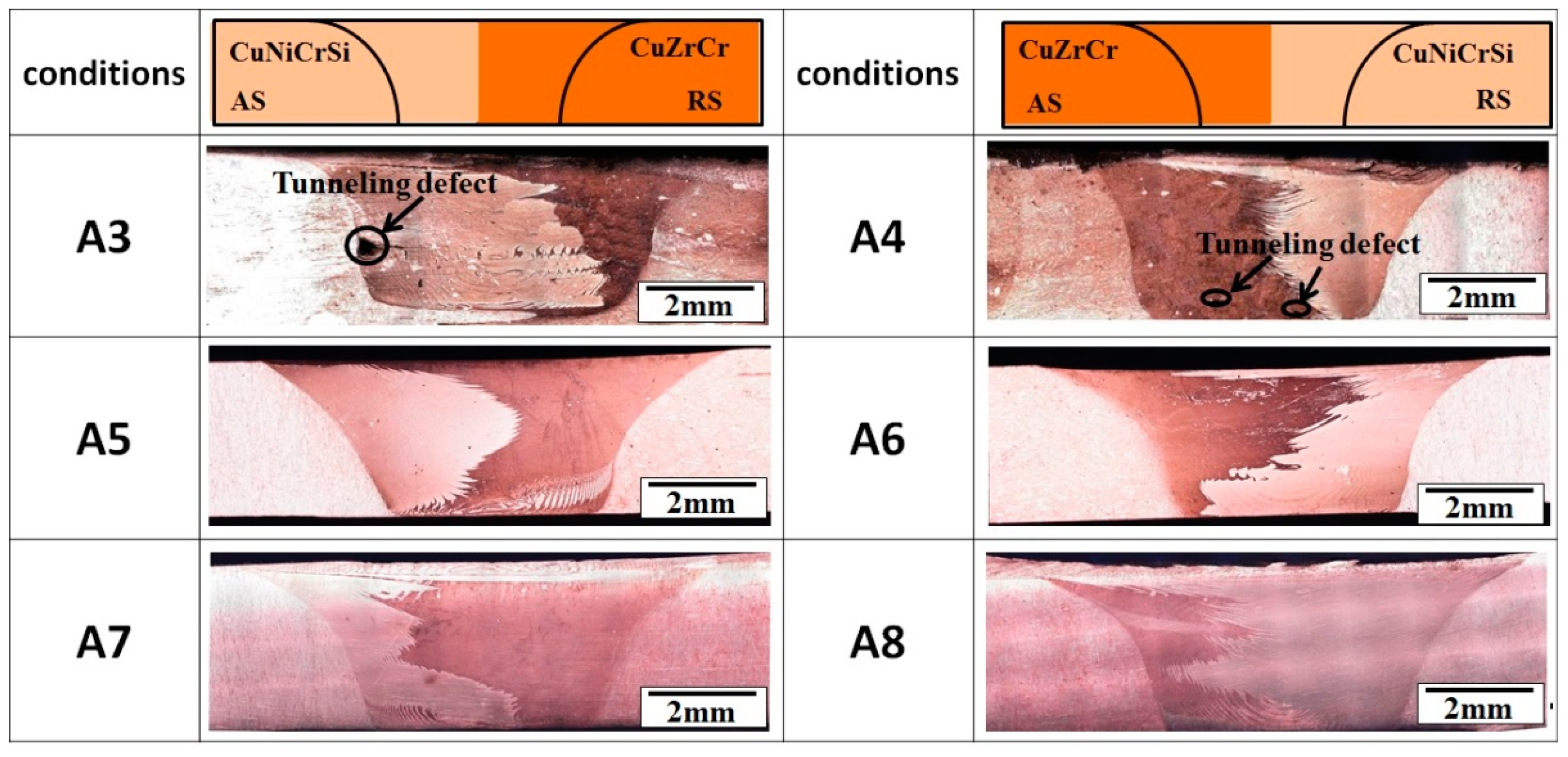
Figure 5.
Inverse pole figure maps in the different regions. (a) CuNiCrSi-BM; (b) CuCrZr-BM; (c) CuNiCrSi-NZ under condition A5; (d) CuCrZr-NZ under condition A5; (e) CuNiCrSi-NZ under condition A7; (f) CuCrZr-NZ under condition A7.
Figure 5.
Inverse pole figure maps in the different regions. (a) CuNiCrSi-BM; (b) CuCrZr-BM; (c) CuNiCrSi-NZ under condition A5; (d) CuCrZr-NZ under condition A5; (e) CuNiCrSi-NZ under condition A7; (f) CuCrZr-NZ under condition A7.
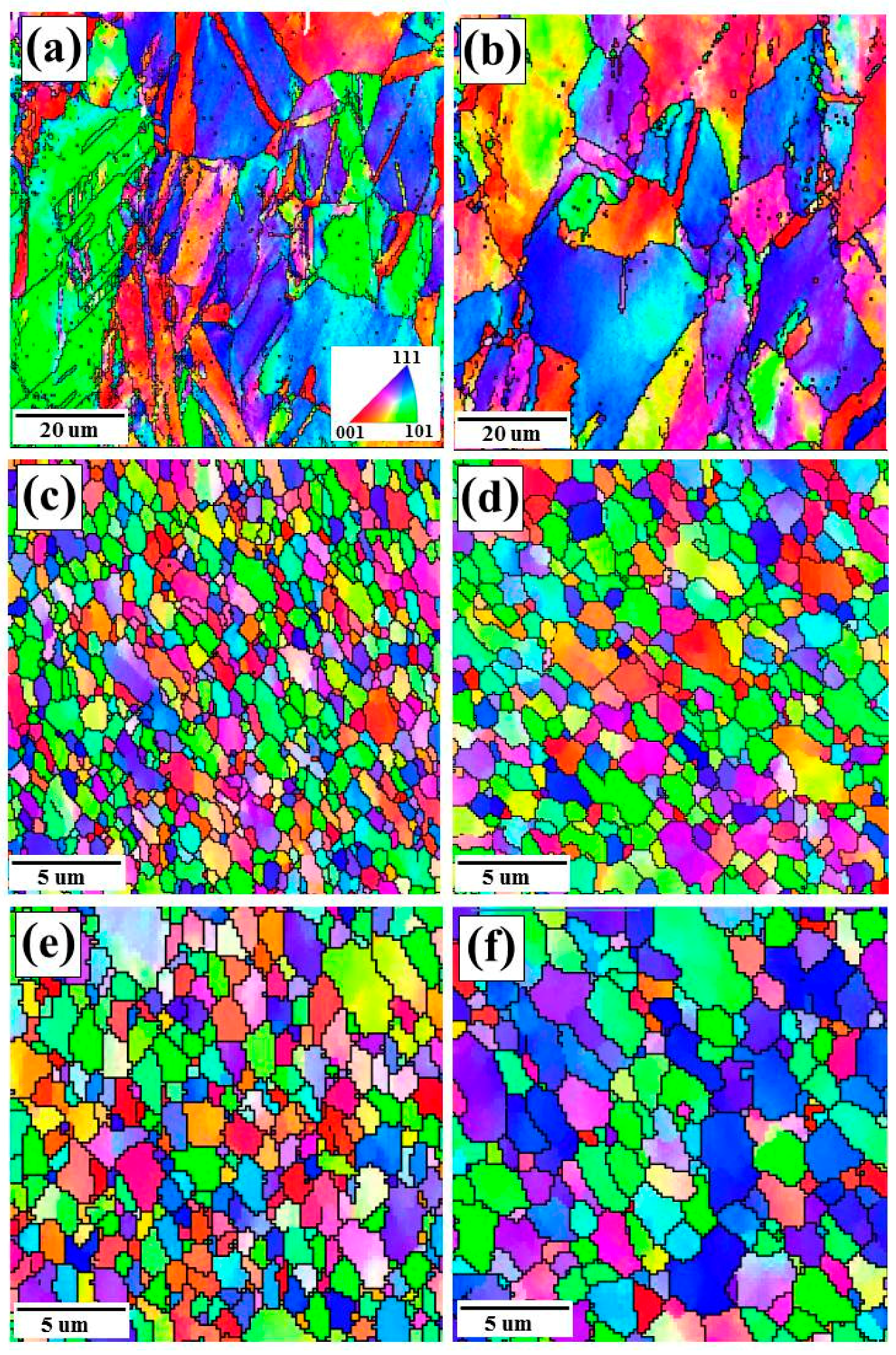
Figure 6.
Grain size frequencies of different regions. (a) CuNiCrSi-BM; (b) CuCrZr-BM; (c) CuNiCrSi-NZ under condition A5; (d) CuCrZr-NZ under condition A5; (e) CuNiCrSi-NZ under condition A7; (f) CuCrZr-NZ under condition A7. (Davg means the average diameter of grains).
Figure 6.
Grain size frequencies of different regions. (a) CuNiCrSi-BM; (b) CuCrZr-BM; (c) CuNiCrSi-NZ under condition A5; (d) CuCrZr-NZ under condition A5; (e) CuNiCrSi-NZ under condition A7; (f) CuCrZr-NZ under condition A7. (Davg means the average diameter of grains).
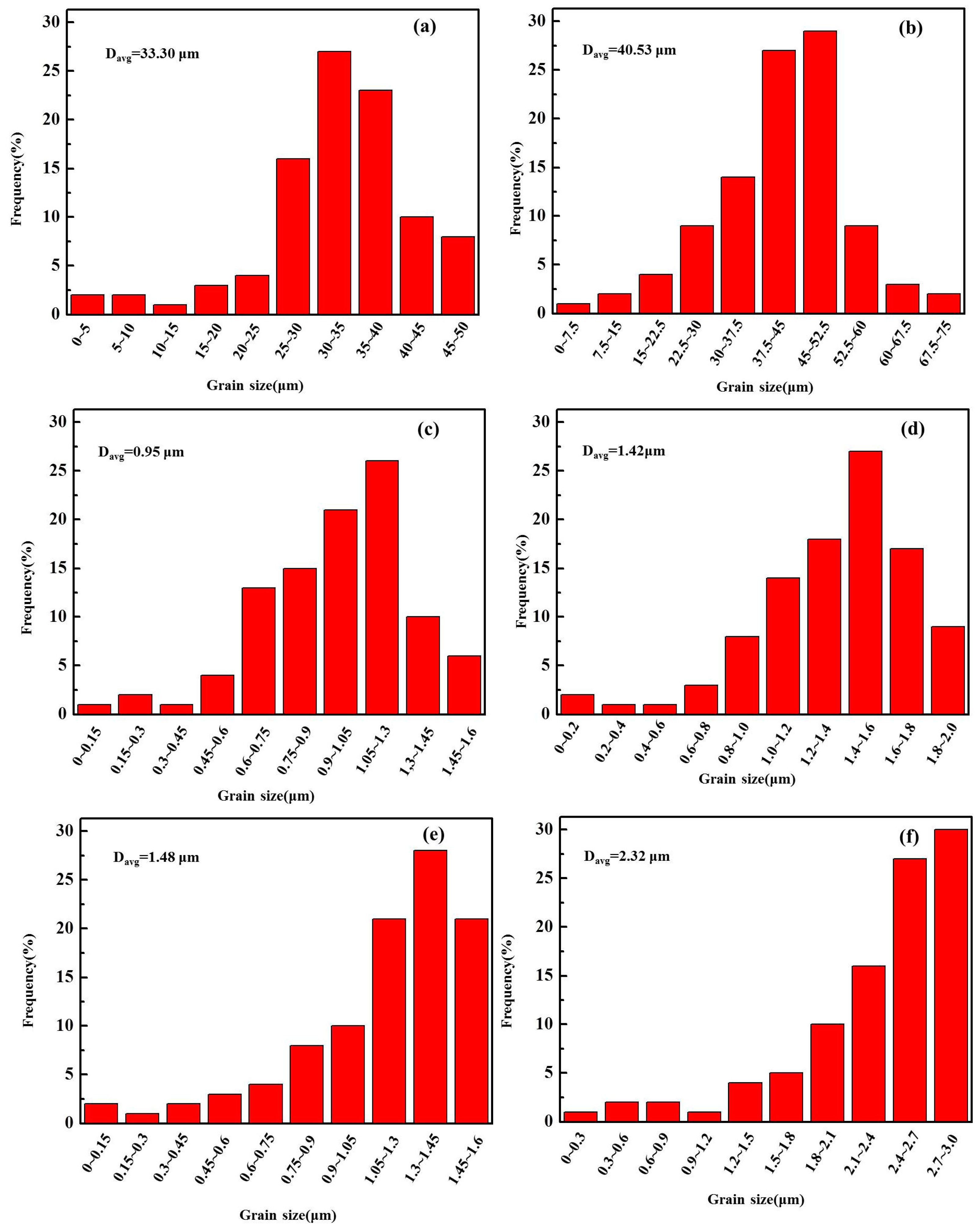
Figure 7.
The bright-field TEM micrographs of samples from different zones at the rotational speed of 1400 rpm (condition A5). (a) CuCrZr-BM in the [011]Cu direction; (b) CuCrZr-NZ in the [011]Cu direction; (b) CuNiCrSi-BM in the [011]Cu direction; (d) CuNiCrSi-BM in the [111]Cu direction; (e) CuNiCrSi-NZ in the [111]Cu direction.

Figure 8.
The bright-field TEM micrographs of samples from the CuCrZr-NZ and CuNiCrSi-NZ when the rotational speed increased to 1700 rpm (condition A7). (a) CuCrZr-NZ in the [011]Cu direction; (b) CuNiCrSi-NZ in the [111]Cu direction.
Figure 8.
The bright-field TEM micrographs of samples from the CuCrZr-NZ and CuNiCrSi-NZ when the rotational speed increased to 1700 rpm (condition A7). (a) CuCrZr-NZ in the [011]Cu direction; (b) CuNiCrSi-NZ in the [111]Cu direction.

Figure 9.
The microhardness along the centreline of dissimilar CuCrZr/CuNiCrSi joints.
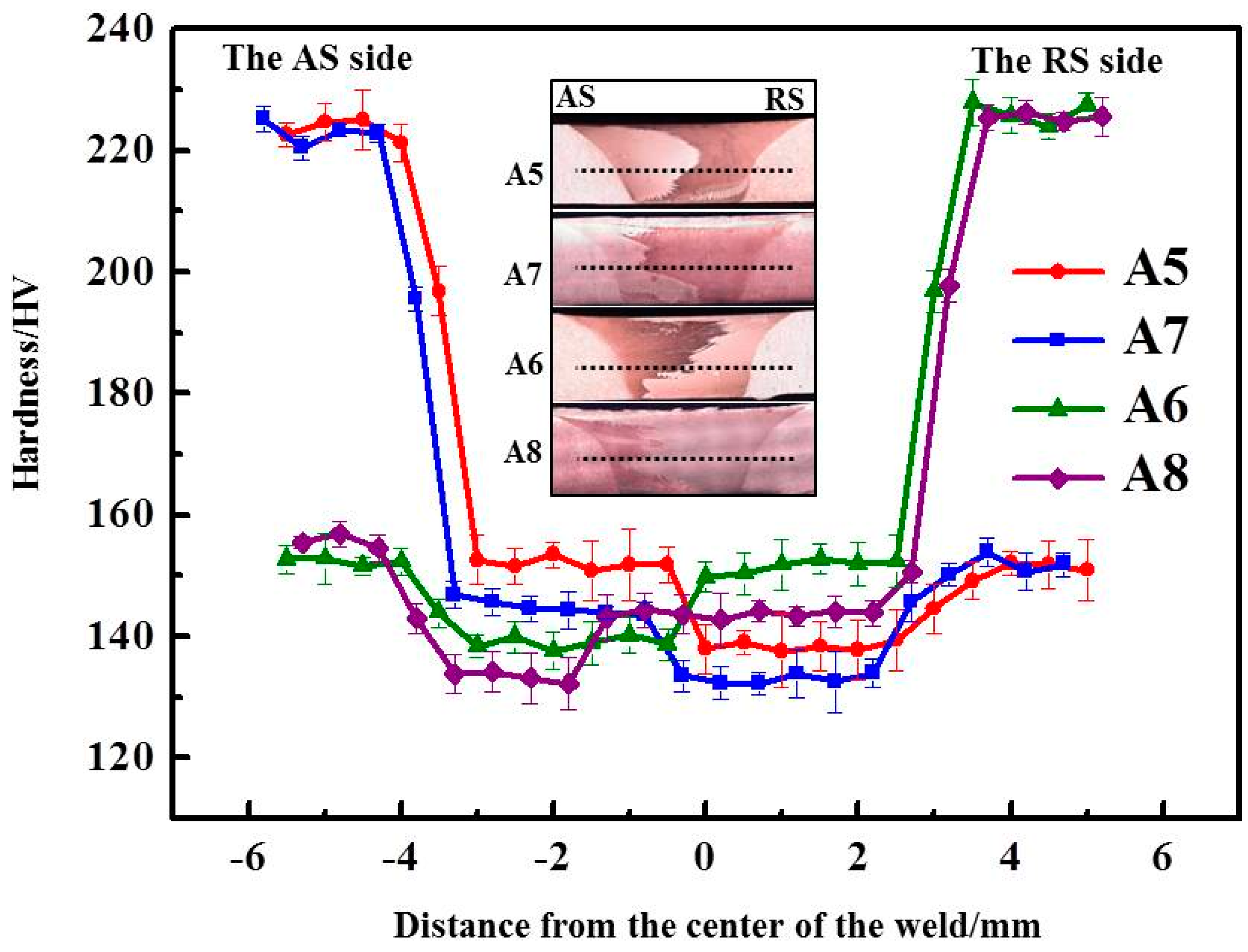
Figure 10.
The mechanical properties of dissimilar joints. (a) The variation tendency of mechanical properties when the CuCrZr alloy is located on the AS; (b) the variation tendency of mechanical properties when the CuNiCrSi alloy is located on the AS; (c) tensile strength of joints. (UTS means the ultimate tensile strength; YS means the yield strength).

Figure 11.
The failure locations of tensile testing specimens under the different conditions A3–A8.
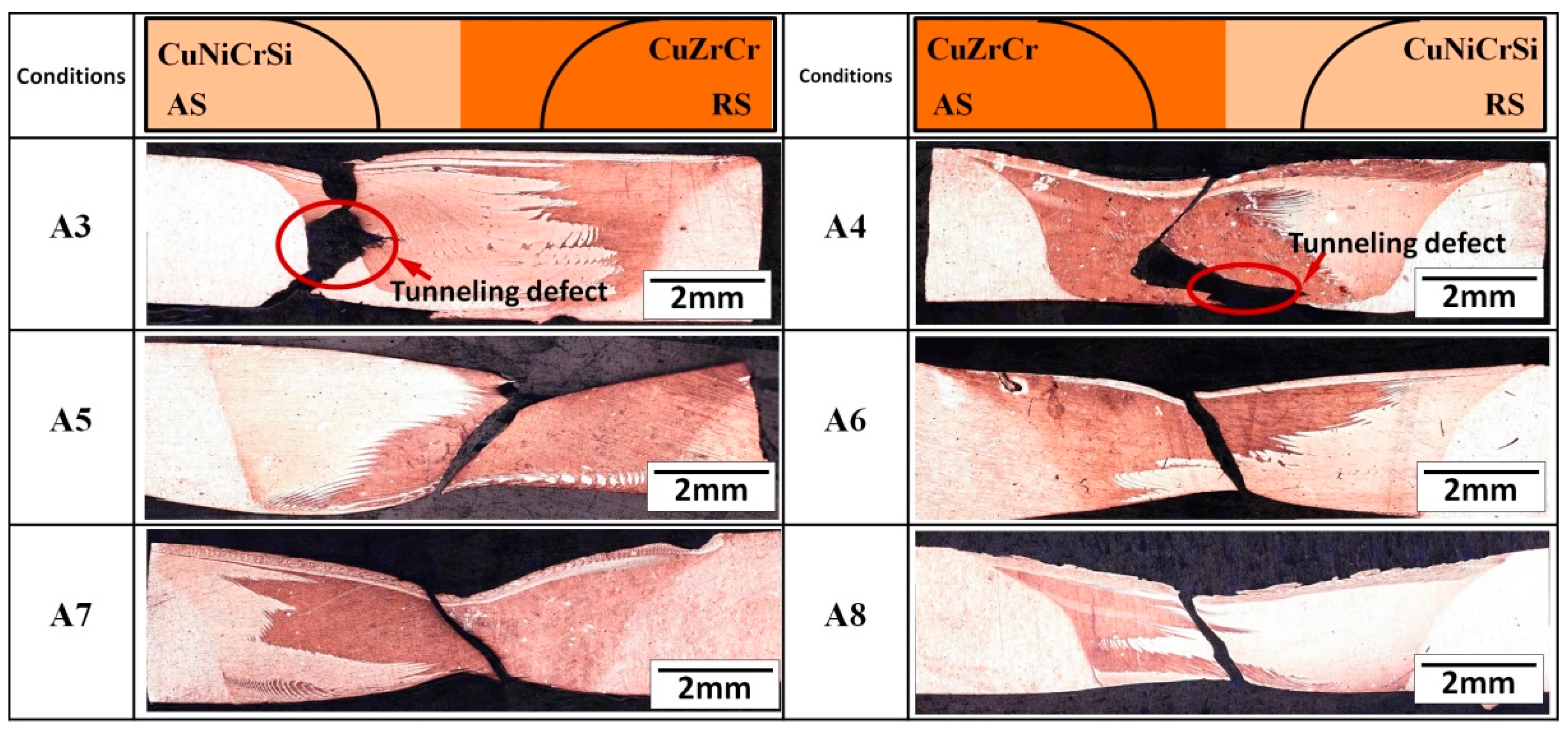
Figure 12.
The SEM micrographs of the fracture surface of the dissimilar joints under conditions A5 and A7.
Figure 12.
The SEM micrographs of the fracture surface of the dissimilar joints under conditions A5 and A7.


Table 1.
The chemical compositions of the CuCrZr alloy and CuNiCrSi alloy.
| Alloy (wt %) | Cu | Al | Mg | Cr | Ni | Zr | Fe | Si |
|---|---|---|---|---|---|---|---|---|
| CuCrZr | Bal. | 0.25 | 0.1 | 0.8 | - | 0.3 | 0.09 | 0.04 |
| CuNiCrSi | Bal. | - | - | 0.5 | 2.0 | - | ≤0.15 | 0.5 |
Table 2.
The welding parameters used in the study.
| Conditions | Material on the Advancing Side (AS) | Material on the Retreating Side (RS) | Rotational Speeds (rpm) | Travel Speed (mm/s) | Tilt Angle (°) |
|---|---|---|---|---|---|
| A1 | CuNiCrSi | CuCrZr | 800 | 150 | 2.5 |
| A2 | CuCrZr | CuNiCrSi | 800 | 150 | 2.5 |
| A3 | CuNiCrSi | CuCrZr | 1100 | 150 | 2.5 |
| A4 | CuCrZr | CuNiCrSi | 1100 | 150 | 2.5 |
| A5 | CuNiCrSi | CuCrZr | 1400 | 150 | 2.5 |
| A6 | CuCrZr | CuNiCrSi | 1400 | 150 | 2.5 |
| A7 | CuNiCrSi | CuCrZr | 1700 | 150 | 2.5 |
| A8 | CuCrZr | CuNiCrSi | 1700 | 150 | 2.5 |
| A9 | CuNiCrSi | CuCrZr | 2000 | 150 | 2.5 |
| A10 | CuCrZr | CuNiCrSi | 2000 | 150 | 2.5 |
Table 3.
The ultimate tensile strength, yield strength, and elongation of different joints.
| Conditions | Material on AS Side | UTS (MPa) | YS (MPa) | Elongation (%) |
|---|---|---|---|---|
| A3 | CuNiCrSi | 296.82 ± 10 | 171.73 ± 5 | 1.32 ± 0.5 |
| A4 | CuCrZr | 321.77 ± 8 | 221.59 ± 5 | 5.1 ± 0.9 |
| A5 | CuNiCrSi | 410.76 ± 12 | 329.82 ± 3 | 25.02 ± 1.2 |
| A6 | CuCrZr | 445.56 ± 9 | 358.38 ± 7 | 24.25 ± 0.8 |
| A7 | CuNiCrSi | 386.09 ± 7 | 318.08 ± 6 | 26.62 ± 1.5 |
| A8 | CuCrZr | 405.78 ± 11 | 338.51 ± 10 | 25.13 ± 1.3 |
| CuNiCrSi | - | 725 ± 13 | 646 ± 9 | 9.5 ± 1.5 |
| CuCrZr | - | 550 ± 15 | 489 ± 10 | 11.5 ± 1.0 |
© 2018 by the authors. Licensee MDPI, Basel, Switzerland. This article is an open access article distributed under the terms and conditions of the Creative Commons Attribution (CC BY) license (http://creativecommons.org/licenses/by/4.0/).
Share and Cite
MDPI and ACS Style
Sun, Y.; He, D.; Xue, F.; Lai, R. Effect of Tool Rotational Speeds on the Microstructure and Mechanical Properties of a Dissimilar Friction-Stir-Welded CuCrZr/CuNiCrSi Butt Joint. Metals 2018, 8, 526. https://doi.org/10.3390/met8070526
AMA Style
Sun Y, He D, Xue F, Lai R. Effect of Tool Rotational Speeds on the Microstructure and Mechanical Properties of a Dissimilar Friction-Stir-Welded CuCrZr/CuNiCrSi Butt Joint. Metals. 2018; 8(7):526. https://doi.org/10.3390/met8070526
Chicago/Turabian StyleSun, Youqing, Diqiu He, Fei Xue, and Ruilin Lai. 2018. "Effect of Tool Rotational Speeds on the Microstructure and Mechanical Properties of a Dissimilar Friction-Stir-Welded CuCrZr/CuNiCrSi Butt Joint" Metals 8, no. 7: 526. https://doi.org/10.3390/met8070526
Note that from the first issue of 2016, this journal uses article numbers instead of page numbers. See further details here.