Article

The Influence of Microstructural Heterogeneity on Mechanical Properties of Friction Stir Welded Joints of T6-Treated Al-Zn-Mg Alloy 7A52

1
School of Materials Science and Engineering, Nanjing University of Science and Technology, Nanjing 210094, China
2
Herbert Gleiter Institute of Nanoscience, Nanjing University of Science and Technology, Nanjing 210094, China
3
State Key Laboratory of Advanced Design and Manufacturing for Vehicle Body, Hunan University, Changsha 410082, China
*
Authors to whom correspondence should be addressed.
Metals 2018, 8(7), 527; https://doi.org/10.3390/met8070527
Submission received: 11 June 2018 / Revised: 1 July 2018 / Accepted: 2 July 2018 / Published: 6 July 2018

Abstract

:
A high strength Al-Zn-Mg alloy 7A52 with T6 treatment was successfully friction stir welded. The grain structure, dislocations and precipitates in typical regions of the weld joint, including the weld nugget zone (WNZ), thermos-mechanically affected zones (TMAZ) and heat affected zones (HAZ) were investigated to understand the mechanical properties of each zone and the weld joint. In WNZ, a relatively higher density of dislocations is observed on the advancing side, caused by vacancy collapse induced by severe plastic deformation during stirring. However, in the center and on the retreating side, the dislocation density is very low. The strength of the WNZ is influenced by grain refinement, solution strengthening, or natural ageing hardening. In TMAZs, different mechanical properties on each side are due to different grain structures and precipitates introduced by the asymmetrical thermo-mechanical cycle. In HAZs, the mechanical properties are a strong function of the ratio of η′ to η phase. Compared to the micro-tensile results, premature failure of the weld joint occurs in HAZs on the advancing side, resulting from stress concentration near the area with the lowest hardness.

Graphical Abstract

1. Introduction

Al-Zn-Mg alloys, as structural materials, are widely used in civil aviation and military vehicles due to their high specific strength, fracture toughness, and excellent resistance to stress corrosion cracking, along with strengthening by natural aging [1,2,3,4,5,6]. However, the welding of the Al-Zn-Mg alloys with high strength is a large problem in the application of engineering because of difficulties arising from melting and solidification during fusion welding such as loss of strength and ductility in heat affected zones (HAZ), hot cracking, porosity, and fusion defects. The 7A52 is a medium strength alloy of Al-Zn-Mg system, which is age-hardenable by forming η-series precipitates [7,8]. This alloy is suitable for welding because the strength can be recovered by natural aging and its welded components are widely used for military and other structural applications.
Friction stir welding (FSW), a promising solid-state process developed by The Welding Institute in Cambridge England, provides potential to join aluminum alloys traditionally considered unweldable. Using this method, the joint may be free from the dendritic structure typical of a fusion-weld joint and has better mechanical properties and lower distortion and residual stresses compared to fusion welding joints [4,9,10,11,12,13]. These improvements are a result of reduced heat input during FSW compared with conventional fusion weld. The solid phase joining of FSW is achieved by introducing frictional heat, interface deformation and solid-state diffusion, which results in gradual local microstructure changes in the aluminum alloy [14,15]. Understanding the microstructural evolution during the thermomechanical process imposed by FSW is a very important step in understanding the weld’s mechanical properties.
A number of research papers have been published on the development of microstructures and mechanical properties [4,9,11,15,16,17]. Concerning Al-Zn-Mg alloys, such studies in alloys 7075 [18,19,20,21], 7050 [10,12,22], 7449 [11], 7039 [4,23,24,25,26,27], 7010 [28] are presented. Results from these studies suggested six different microstructure zones: the nugget in the center of the weld (WNZ), thermo-mechanical affected zones (TMAZ) on each side of the nugget and under the shoulder contact zone, heat affected zones (HAZ) in between the TMAZ and the unaffected parent material. An asymmetrical microstructure produced by FSW has been revealed by hardness testing. This is due to differences in strain levels and thermal cycles on the advancing side and on the retreating side. In addition to the grain structure evolution, different precipitate distributions are induced within each zone by the severe thermo-mechanical condition, which results in higher deformation and temperature gradients to the passing tool.
Although microstructural evolution has been reported, the direct link between microstructures and tensile properties has not been established. Previous works have noted more interesting observations on microstructures but not macroscopic tensile properties. The present paper focuses on the direct relationship between microstructures and micro-tensile properties within each zone, thus providing fracture mechanism from both a micro-view and macro-view.

2. Material and Experimental Details

The base metal was a T6-treated Al-Zn-Mg alloy of 7A52 rolled sheets with the composition listed in Table 1. After quenching, its supersaturated solid solution (SSS) decomposed, as the following sequence, during artificial aging [29,30,31]:
The rod-like η (MgZn2), an equilibrium phase incoherent with the Al matrix, makes the alloy soften [32,33]. The η′ and GPη′ zones, with a disc-like shape and well-ordered structure, are coherent with the Al matrix and believed to be the main strengthening phases in T6-treated alloy [34,35,36]. GPI zones or solute clusters have no obvious periodical lattice, forming at the very early stage of aging and being responsible for the initial increase in hardness [36,37,38,39].
A commercial gantry type FSW machine (FSW-LM-025-2030, Jiangsu Ruicheng Machinery Co., Ltd (RCM), Yixing, China) was employed to make FSW joints in position control mode, with working table of size 2.4 m × 1.4 m. The pin rotational speed and welding speed were in the range of 100–1500 rpm and 0–1500 mm/min respectively. The friction stir butt welds rolled plates of size 250 mm × 120 mm × 16 mm of T6-treated 7A52 aluminum alloy were obtained using a welding speed of 150 mm/min and rotational speed of 400 rpm, employing single pass welding procedure. The plates were held firmly using a specially designed and developed fixture. The welding direction was normal to the rolling direction. An FSW tool was made of die steel and had a flat shoulder with a truncated conical pin with an anticlockwise thread of 1 mm pitch. The depth of the shoulder plunge was kept at 0.2 mm from workpiece surface.
The developed joints were examined by visual inspection to make sure no there were no obvious defects (like lack of fill/penetration, cracks, excessive flash generation) on the crown and root surface. The qualified joints were then inspected using optical microscopy to further exclude those with the presence of kissing bonds or zigzag line defects. The perfect joints were extracted for mechanical property measurement and microstructure analysis. Generally, the FSW joint was divided into three different zones: the WNZ, the TMAZ and the HAZ. Microhardness and microtensile tests were employed to characterize mechanical properties of different zones. Microhardness variation across the joint was measured using an HMV-G 21DT Micro Vickers Hardness Tester (SHIMADZU, Kyoto, Japan) with an applied load of 100 g and a holding time of 10 s, each value was obtained by averaging at least five successive measurements. The tensile experiments were performed on an Instron 5892 machine (Instron Limited Inc., Boston, MA, USA) with a constant strain rate of 10−3 s−1. The dog-bone-shaped specimens used in the tensile tests were shaped by spark erosion to have a rectangular gauge section of 2 × 0.5 mm2 and a gauge length of 5 mm. A contactless video strain gauge based on digital image correlation (DIC) technique was developed to accurately measure the strain in the gauge section. Geometries and orientations of the tensile samples in FSW joints are schematically showed in Figure 1. The specimen axis was aligned perpendicular to the welding direction. Larger tensile samples, whose gauge length covers different zones of the joint, were designed to examine the tensile properties of the FSW joint.
FSW joints were polished and etched in Keller’s reagent (2.5 mL nitric acid, 1.0 mL hydrofluoric acid, 1.5 mL hydrochloric acid mixed with 95 mL distilled water) for 30 s to observe grain morphology using an optical microscope (Carl Zeiss Inc., Jena, Germany). The grain structures were characterized by electron back-scattered diffraction (EBSD) attached to a focal-ion beam (FIB)/SEM system (Carl Zeiss Auriga 45–66, Carl Zeiss Inc., Jena, Germany). The EBSD specimens were prepared using electrochemical polish in a solution mixed of 10% perchloric acid and 90% ethyl alcohol at a voltage of 15 mV and a temperature of –30 °C. A FEI Titan G2 60–300 transmission electron microscope (TEM, Thermo Fisher Scientific Inc., Waltham, MA, USA) with a spherical aberration corrector under the objective lens operated at 300 kV was used to examine precipitates in different zones. With the help of the trace of hardness test, the TEM specimens were extracted accurately in a certain zone. TEM specimens were prepared by mechanical grinding and subsequently electro-polish using a twinjet unit (TJ100-SE, LEBOscience, Jiangyin, Jiangsu, China) with an electrolyte of 30% nitric acid in methanol at –25 °C and 20 V. Specimens for microstructure examination were sectioned from the transverse section perpendicular to the welding direction because the transverse section comprises all the zones with different microstructures and associated mechanical properties.

3. Results

3.1. Mechanical Properties
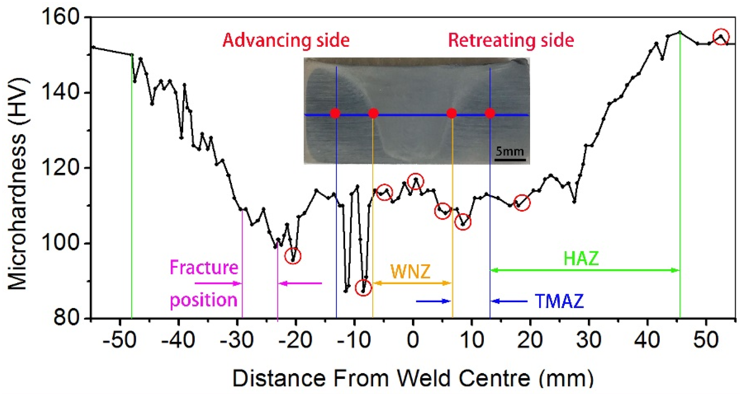
3.1.1. Hardness

The hardness variation across the weld joint along the central line of the transverse section is presented in Figure 2, where the different zones are indicated. The average hardness of T6-treated base metal is about 152 HV. The hardness curve of the FSW joint is asymmetrical with respect to the weld center because of different microstructures on the advancing side and the retreating side introduced by the non-uniform field of plastic flow. On both sides, in HAZs next to the base metal, the hardness slopes downward from the base metal to the weld, but the lowest hardness presents on the advancing side, which is 10 HV lower than that on the retreating side. In TMAZs in between HAZs and the WNZ, the hardness fluctuates largely on the advancing side with an amplitude of up to 20 HV, while the hardness holds steady on the retreating side. In TMAZs of the FSW joint on the advancing side, the bottom hardness is even lower than the lowest hardness in HAZs, and the top hardness is the same as that in the WNZ, where the hardness is about 114 HV.

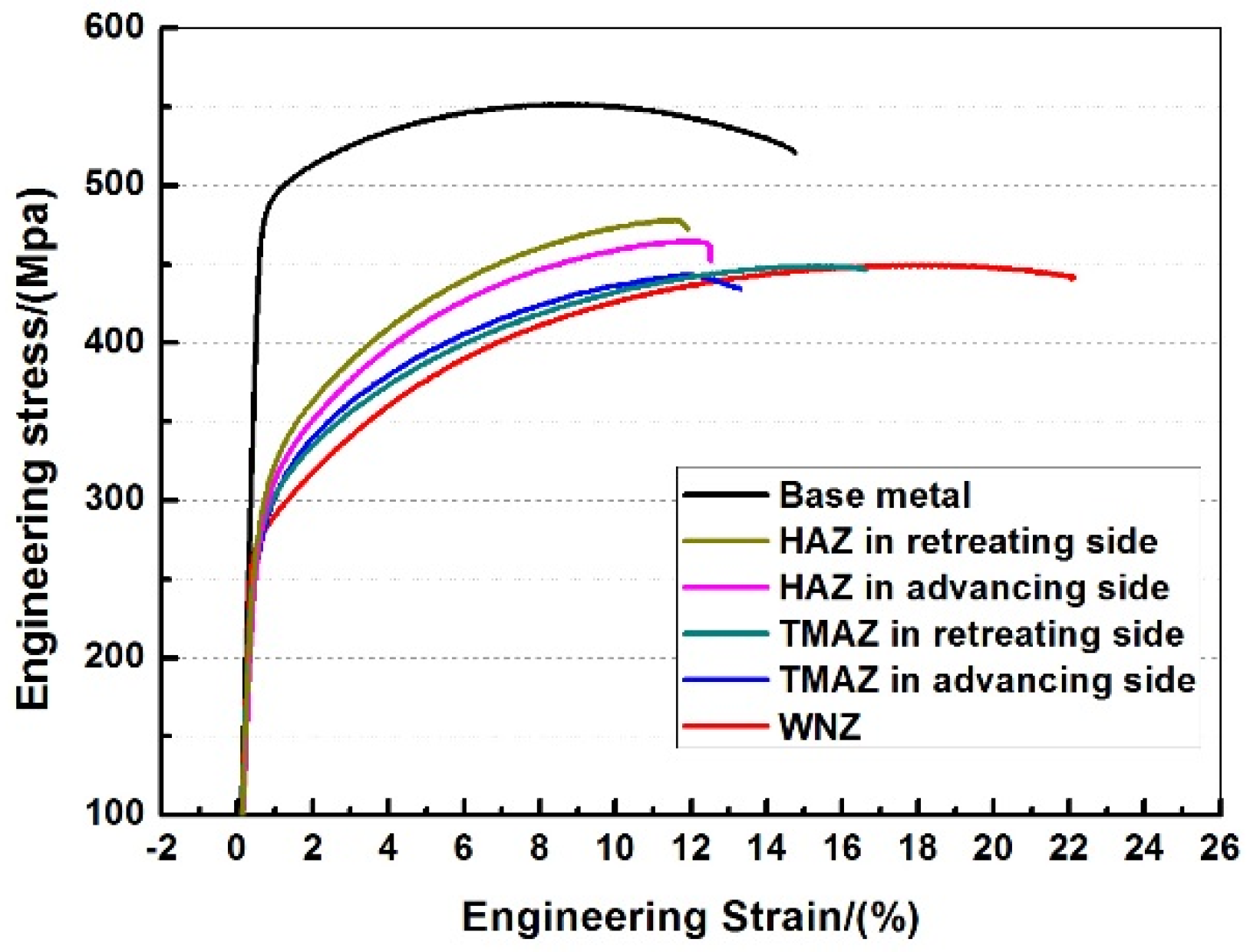
3.1.2. Tensile Properties

Tensile curves of samples obtained in each zone of FSW joints are presented in Figure 3, and the corresponding mechanical properties are summarized in Table 2. Obviously, the tensile strength of the weld is lower than that of the T6-treated base metal, the strength efficiency is located in the range of 80–87%. The TMAZs on both sides and the WNZ have the similar ultimate tensile strength, but a strong difference in yield strength and elongation. The WNZ has the lowest yield strength but the highest elongation. The TMAZs on both sides have similar yield strengths but big differences in elongation. The strength of the HAZ is higher than that of the TMAZ on both sides, but the elongation of the HAZ is lower than that of the TMAZ on both sides. This difference is even more marked on the retreating side. The tensile properties of the whole FWS weld joint are much lower than that of each zone obtained by micro-tensile, and the fracture position is near the region with the lowest hardness (Figure 2), where stress concentration easily occurs during tensile.

3.2. Microstructures
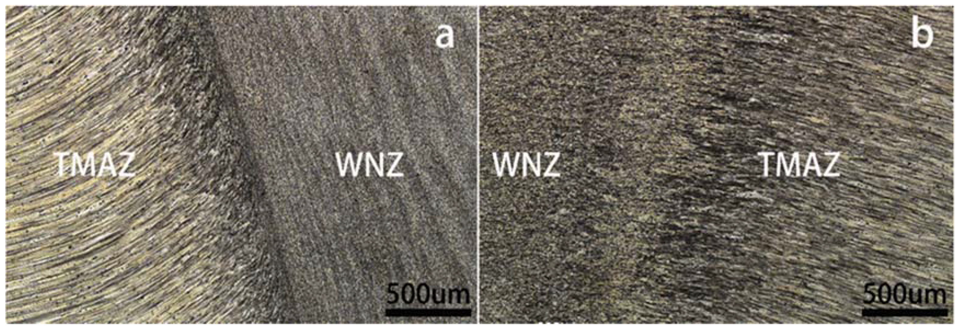
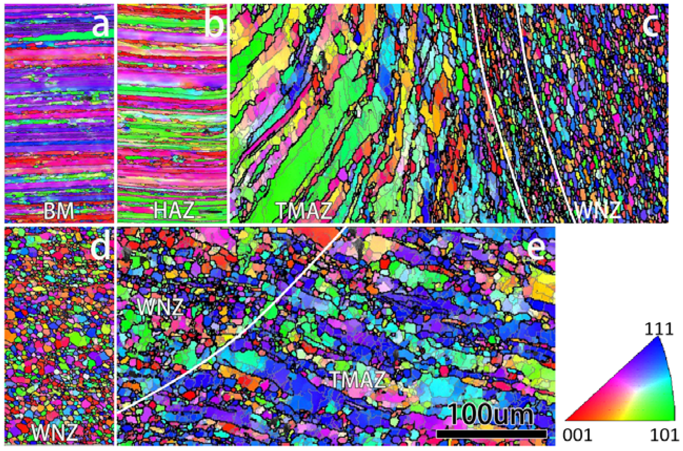
3.2.1. Grains

The photograph of the selected FSW joint is shown as the inset in Figure 2, showing the weld is free of defects. The FSW joint is a symmetric nugget zone about the weld center line and has a size of the tool pin diameter. The microstructures across the weld joint along the central line of the transverse section were examined. Micrographs near the joint line are shown in Figure 4, where the most prominent feature is the sharp bending of grain structures in TMAZs due to severe plastic deformation. Moreover, the grains are more curved in the TMAZ on the advancing side than that on the retreating side, suggesting more severe deformation occurs in TMAZ on the advancing side.
The orientation map of grains in and adjacent to different zones located by hardness measurement are shown in Figure 5. Figure 5a shows the as-rolled base metal comprises of partially recrystallized lamellar grains, in some of which subgrains are observed with the size of a few microns. Figure 5b shows the grain structure in HAZ, which has not been disturbed mechanically by FSW, is very similar to that of the base metal, except for a few more recrystallized grains due to heat transport from welding. In the TMAZ on the advancing side, there are mainly high angle elongated grains with large thickness and some subgrains in the interior. These grains bend too far along the direction of metal flow. On the other hand, in the TMAZ on the retreating side, high angle elongated grains with large thickness coexist with equiaxed recrystallized grains. Obviously, in the TMAZ on the retreating side the degree of recrystallization is higher than that on the advancing side. The WNZ contains fine, equiaxed grains (Figure 5c–e), with an average diameter of 4.7 μm, due to dynamic recrystallization. At the joint line (bordered by white lines in Figure 5c) between the TMAZ on the advancing side and the WNZ, finer grains are observed with an average diameter of 2.7 μm (Figure 5c). However, on the retreating side it was found the transition of grains was pretty smooth from the TMAZ to the WNZ.

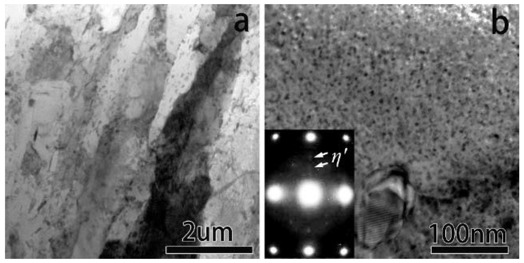
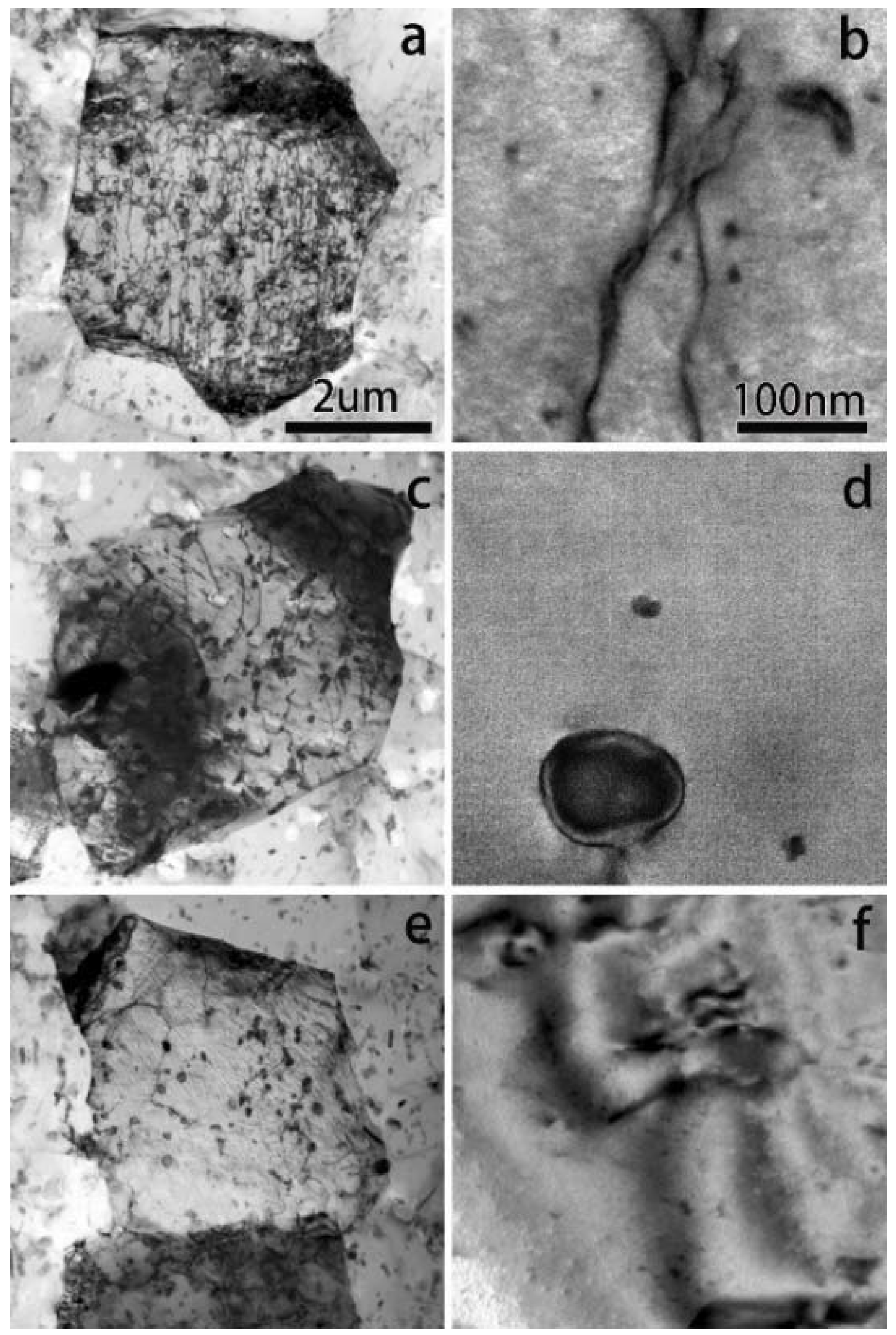
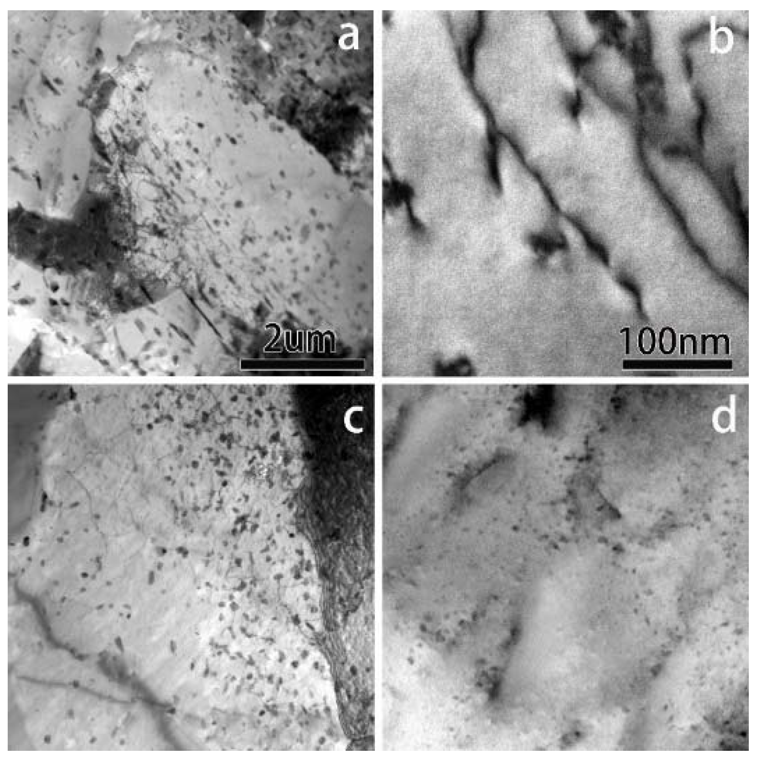
3.2.2. Microstructures in the Interior of Grains

The hardness’ circled in Figure 2 were selected for TEM examination and the results are shown in Figure 6, Figure 7, Figure 8 and Figure 9. Figure 6 shows the microstructures in unaffected base metal with T6-treatment. Figure 6a indicates that grains in the base metal contain a relatively low dislocation density, and a great number of the second phases (CrMn-rich and MgZn-rich). Figure 6b demonstrates a high density of nanoprecipitates distributing homogenously in the interior of grains. They are mostly η′ phase, identified by their disc-like morphology and the selected area electron diffraction (SAED) pattern along <112>Al zone axis as inset in Figure 6b.
Figure 7 shows the microstructures in the WNZ of the FSW joint. Although the grains are all recrystallized and equiaxed, the dislocation structures in the grains are absolutely different across the WNZ. The dislocation density decreases gradually from the advancing side to the retreating side traversing through the whole WNZ, as shown in Figure 7a,c,e, the dislocation recovery is speculated to be related to the elevated temperature on the retreating side induced by friction and stir. On the advancing side (Figure 7a), there is a high density of linear dislocations resulting from vacancies collapsing, due to severe plastic deformation during stir. A common feature of dislocations in the whole WNZ is that they are pinned by the second phase particles. In the whole WNZ, no precipitate is observed (Figure 7b,d,f), some Zn and Mg atoms segregate at the interface of the CrMn-rich particles and the matrix or form a ZnMg-rich second phase, but most of the alloying atoms are soluted into in the matrix.
Figure 8 shows microstructures in HAZs on both sides. The second phases and dislocations in the HAZ are both very similar to those in the matrix, as shown in Figure 8a,c. Compared with the matrix, in the HAZ, the big microstructural change is nano-sized precipitates, which are much larger in size. Especially on the advancing side, most of the precipitates in the HAZ are stable η-phase (Figure 8b), which make the HAZ soften, resulting in the lowest hardness (Figure 2). While on the retreating side in the HAZ, precipitates are composed of metastable η′ phase and stable η phase (Figure 8d). The η′ is the strengthening phase, while the η is the softening phase. With the effect of the two aspects, the HAZ on the retreating side has a lower hardness than the matrix, but a little higher hardness than the HAZ on the advancing side. The hardness of the HAZ is significantly dependent on the number ratio of η′ precipitates, which is largely affected by heat input. With the influence of the heat input decreasing, the hardness increases gradually and gets close to that of the matrix, as the distance to the WNZ increases.
Figure 9 shows the microstructures of the TMAZ which are more complex and influenced by heat input and by severe plastic deformation. A high density of dislocations pinned by the second phases are observed in the TMAZ on both sides (Figure 9a,c). The second phases in the TMAZ are significantly more than those in the matrix, because there is a large volume of coarse (Mg, Zn)-rich particles forming in the TMAZ. The distribution of these particles in the TMAZ is not uniform, more particles locate in the dislocation pile-up zone (Figure 9a,c). Further magnification of the TMAZ in Figure 9b,d shows that no nano-precipitate is observed on the advancing side (Figure 9b), but non-uniform nano-precipitates are observed on the retreating side (Figure 9d). On the advancing side, all precipitates grew into a coarser (Mg, Zn)-rich second phase, influenced by dislocation and by heat input. On the retreating side, with higher temperature (induced by stir and friction) than on the advancing side but lower temperature than the WNZ, precipitates were partially dissolved.

4. Discussion

The heterogeneity with respect to microstructure and mechanical properties across the FSW joint is well known due to the development of a gradient in temperature distribution and plastic strain induced during FWS. Although there are is a weld nugget zone, a heat affected zone and a thermo-mechanically affected zone, the microstructural and mechanical properties changes were found to be gradual and less drastic than those occurring in a fusion weld.
The most significant changes in microstructure, occurring in the WNZ, were the recrystallization of the elongated grains and the full solution of nano-sized precipitates due to temperatures in the WNZ as high as 400 to 480 °C [21]. The strength of the WNZ could be attributed to three mechanisms, i.e., solution strengthening by Mg and Zn, grain boundary strengthening facilitated by grain refinement, and dislocations. The contribution of dislocations can be neglected here because of a very low density of dislocations in the center and on the retreating side, in spite of a relative high density of dislocations on the advancing side. Although no precipitate is observed in the WNZ using TEM, the hardness will increase with storage time at room temperature, resulting in nano-clusters (or GPI zones) forming during “natural aging” as reported [31,40,41]. With an increase in storage time, the solution strengthening will be replaced by the contribution of nano-clusters (or GPI zones), leading to an increase in strength.
In the TMAZs of the FSW joints, grains were deformed. On the advancing side, recrystallization was not remarkable as temperature rise induced by deformation was less and could not initiate the same recrystallization as that in the WNZ. However, partial recrystallization was found in the TMAZ on the retreating side, due to higher temperature induced by stirring. The temperature change also caused different evolution of precipitates. In the TMAZ on the advancing side, precipitates grew into sub-micro and even micro particles, while in the TMAZ on the retreating side precipitates partially dissolved. These different microstructures in TMAZs leads to different mechanical properties. In the TMAZ on the advancing side, the hardness fluctuates largely because of non-uniform second phases and no nano-precipitates. In the TMAZ on the retreating side, the hardness remains stable because of non-dissolution precipitates offsetting the non-uniform second phase. Thus, these microstructural differences resulted in higher strength and better elongation on the retreating side than on the advancing side.
In HAZs of the FWS joints, no big changes occurred for grains compared with the base metal. The mechanical properties are due to precipitates. More η precipitates result in lower strength and better elongation. The zone with the lowest hardness in Figure 2 is very narrow (~5 mm) on the advancing side, this has no big influence on the micro-tensile result but remarkable negative effects on the tensile properties of a large specimen including the base metal and the whole joint because the stress concentration in the lowest hardness zone becomes more pronounced at excessive strength than at low strength conditions, resulting in the lowest tensile elongation and premature failure.

5. Conclusions

FWS joints show significant heterogeneity with respect to microstructure and mechanical properties through the joints at the same thickness, primarily due to development of a gradient in temperature distribution and plastic strain introduced during FSW.
(1)
The hardness curve of the FSW joint is asymmetrical with respect to the weld center because of different microstructures on the advancing side and on the retreating side, introduced by non-uniform field of plastic flow.
(2)
Micro-tensile test results show the HAZ on the advancing side has lower strength but higher elongation than that on the retreating side because in the HAZ on the retreating side there are more η′ precipitates providing strengthening, although grain structures and the second phase are very similar in the HAZs on both sides.
(3)
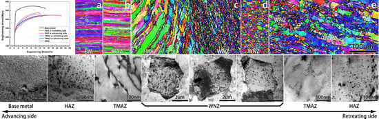
Micro-tensile test results show the TMAZ on the advancing side has lower strength and elongation than on the retreating side. The higher strength is partially due to nano-sized precipitates, while the higher elongation is due to the higher degree of recrystallization, compared with the TMAZ on the advancing side.
(4)
Tensile tests with the large sample show that fracture occurs near the position in the HAZ on the advancing side with the lowest hardness. Both strength and elongation are much lower than in all other zones due to stress concentration in the area with the lowest hardness.
(5)
In the WNZ, the dislocation density gradually decreases from the advancing side to the retreating side, although they both contain only dynamic recrystallized grains. These dislocations are mainly caused by vacancy collapse induced by severe plastic deformation during FWS.
(6)
The mechanical properties of the FWS joints depend on the hardness difference throughout the joint. With larger differences in hardness, the stress concentration in the lowest hardness zone becomes more pronounced, resulting in premature failure and lowest tensile elongation.

Author Contributions

Conceptualization, J.L. and K.W.; Methodology, J.L., Y.J. and Y.Q.; Validation, J.L., Y.Q. and Y.J.; Formal Analysis, J.L.; Investigation, Y.J., Y.Q. and Y.O.; Resources, K.W.; Data Curation, Y.Q. and Y.J.; Writing-Original Draft Preparation, Y.J., Y.Q. and J.L.; Writing-Review & Editing, J.L.; Supervision, K.W. and J.L.; Project Administration, K.W. and J.L.; Funding Acquisition, K.W. and J.L.

Funding

This research was funded by the National Key R&D Program of China (No. 2017YFA0204403), the National Natural Science Foundation of China (No. 51301064, 51505226), State Key Laboratory of Advanced Design and Manufacturing for Vehicle Body at Hunan University (No. 31715009), the Fundamental Research Funds for the Central Universities (No. 30918011341).

Acknowledgments

All TEM experiments were performed at the Materials Characterization and Research Center of Nanjing University of Science and Technology.

Conflicts of Interest

The authors declare no conflict of interest.

References

  1. Wang, S.S.; Jiang, J.T.; Fan, G.H.; Panindre, A.M.; Frankel, G.S.; Zhen, L. Accelerated precipitation and growth of phases in an Al-Zn-Mg-Cu alloy processed by surface abrasion. Acta Mater. 2017, 131, 233–245. [Google Scholar] [CrossRef]
  2. Ma, K.; Hu, T.; Yang, H.; Topping, T.; Yousefiani, A.; Lavernia, E.J.; Schoenung, J.M. Coupling of dislocations and precipitates: Impact on the mechanical behavior of ultrafine grained Al-Zn-Mg alloys. Acta Mater. 2016, 103, 153–164. [Google Scholar] [CrossRef]
  3. Williams, J.C.; Starke, E.A. Progress in structural materials for aerospace systems 11 The Golden Jubilee Issue-Selected topics in Materials Science and Engineering: Past, Present and Future, edited by S. Suresh. Acta Mater. 2003, 51, 5775–5799. [Google Scholar] [CrossRef]
  4. Sharma, C.; Dwivedi, D.K.; Kumar, P. Influence of pre-weld temper conditions of base metal on microstructure and mechanical properties of friction stir weld joints of Al-Zn-Mg alloy AA7039. Mater. Sci. Eng. 2015, 620, 107–119. [Google Scholar] [CrossRef]
  5. Starke, E.A.; Staley, J.T. Application of modern aluminum alloys to aircraft. Prog. Aerosp. Sci. 1996, 32, 131–172. [Google Scholar] [CrossRef]
  6. Zhang, Z.; Xiao, B.L.; Ma, Z.Y. Hardness recovery mechanism in the heat-affected zone during long-term natural aging and its influence on the mechanical properties and fracture behavior of friction stir welded 2024Al–T351 joints. Acta Mater. 2014, 73, 227–239. [Google Scholar] [CrossRef]
  7. Hornbogen, E. Hundred years of precipitation hardening. J. Light Met. 2001, 1, 127–132. [Google Scholar] [CrossRef]
  8. Lendvai, J. Precipitation and Strengthening in Aluminium Alloys. Mate. Sci. Forum 1996, 217, 43–56. [Google Scholar] [CrossRef]
  9. Liu, F.C.; Nelson, T.W. Grain structure evolution, grain boundary sliding and material flow resistance in friction welding of Alloy 718. Mater. Sci. Eng. 2018, 710, 280–288. [Google Scholar] [CrossRef]
  10. Komarasamy, M.; Alagarsamy, K.; Ely, L.; Mishra, R.S. Characterization of 3″ through-thickness friction stir welded 7050-T7451 Al alloy. Mater. Sci. Eng. 2018, 716, 55–62. [Google Scholar] [CrossRef]
  11. Dos Santos, J.F.; Staron, P.; Fischer, T.; Robson, J.D.; Kostka, A.; Colegrove, P.; Wang, H.; Hilgert, J.; Bergmann, L.; Hütsch, L.L.; et al. Understanding precipitate evolution during friction stir welding of Al-Zn-Mg-Cu alloy through in-situ measurement coupled with simulation. Acta Mater. 2018, 148, 163–172. [Google Scholar] [CrossRef]
  12. Sun, T.; Reynolds, A.P.; Roy, M.J.; Withers, P.J.; Prangnell, P.B. The Effect of Shoulder Coupling on the Residual Stress and Hardness Distribution in AA7050 Friction Stir Butt Welds. Mater. Sci. Eng. 2017. [Google Scholar] [CrossRef]
  13. Hannard, F.; Castin, S.; Maire, E.; Mokso, R.; Pardoen, T.; Simar, A. Ductilization of aluminium alloy 6056 by friction stir processing. Acta Mater. 2017, 130, 121–136. [Google Scholar] [CrossRef]
  14. Malard, B.; De Geuser, F.; Deschamps, A. Microstructure distribution in an AA2050 T34 friction stir weld and its evolution during post-welding heat treatment. Acta Mater. 2015, 101, 90–100. [Google Scholar] [CrossRef] [Green Version]
  15. Xu, W.F.; Liu, J.H.; Chen, D.L.; Luan, G.H.; Yao, J.S. Change of microstructure and cyclic deformation behavior along the thickness in a friction-stir-welded aluminum alloy. Scr. Mater. 2012, 66, 5–8. [Google Scholar] [CrossRef]
  16. Sato, Y.S.; Watanabe, H.; Kokawa, H. Grain growth phenomena in friction stir welded 1100 Al during post-weld heat treatment. Sci. Technol. Weld. Join. 2007, 12, 318–323. [Google Scholar] [CrossRef]
  17. Cabibbo, M.; McQueen, H.J.; Evangelista, E.; Spigarelli, S.; Di Paola, M.; Falchero, A. Microstructure and mechanical property studies of AA6056 friction stir welded plate. Mater. Sci. Eng. A 2007, 460–461, 86–94. [Google Scholar] [CrossRef]
  18. Fratini, L.; Buffa, G.; Shivpuri, R. Mechanical and metallurgical effects of in process cooling during friction stir welding of AA7075-T6 butt joints. Acta Mater. 2010, 58, 2056–2067. [Google Scholar] [CrossRef]
  19. Cai, B.; Adams, B.L.; Nelson, T.W. Relation between precipitate-free zone width and grain boundary type in 7075-T7 Al alloy. Acta Mater. 2007, 55, 1543–1553. [Google Scholar] [CrossRef]
  20. Ma, Z.Y.; Mishra, R.S. Cavitation in superplastic 7075Al alloys prepared via friction stir processing. Acta Mater. 2003, 51, 3551–3569. [Google Scholar] [CrossRef]
  21. Rhodes, C.G.; Mahoney, M.W.; Bingel, W.H.; Spurling, R.A.; Bampton, C.C. Effects of friction stir welding on microstructure of 7075 aluminum. Scr. Mater. 1997, 36, 69–75. [Google Scholar] [CrossRef]
  22. Su, J.Q.; Nelson, T.W.; Mishra, R.; Mahoney, M. Microstructural investigation of friction stir welded 7050-T651 aluminium. Acta Mater. 2003, 51, 713–729. [Google Scholar] [CrossRef]
  23. Sharma, C.; Dwived, D.K.; Kumar, P. Friction Stir Welding of Al–Zn–Mg Alloy AA7039. In Light Metals 2012; Suarez, C.E., Ed.; Springer: Cham, Switzerland, 2016; pp. 503–507. [Google Scholar]
  24. Singh, R.K.R.; Sharma, C.; Dwivedi, D.K.; Mehta, N.K.; Kumar, P. The microstructure and mechanical properties of friction stir welded Al-Zn-Mg alloy in as welded and heat treated conditions. Mater. Des. 2011, 32, 682–687. [Google Scholar] [CrossRef]
  25. Sharma, C.; Dwivedi, D.K.; Kumar, P. Effect of welding parameters on microstructure and mechanical properties of friction stir welded joints of AA7039 aluminum alloy. Mater. Des. 2012, 36, 379–390. [Google Scholar] [CrossRef]
  26. Sharma, C.; Dwived, D.K.; Kumar, P. Effect of post weld heat treatments on microstructure and mechanical properties of friction stir welded joints of Al-Zn-Mg alloy AA7039. Mater. Des. 2013, 43, 134–143. [Google Scholar] [CrossRef]
  27. Sharma, C.; Dwivedi, D.K.; Kumar, P. Fatigue behavior of friction stir weld joints of Al–Zn–Mg alloy AA7039 developed using base metal in different temper condition. Mater. Des. 2014, 64, 334–344. [Google Scholar] [CrossRef]
  28. Steuwer, A.; Dumont, M.; Peel, M.; Preuss, M.; Withers, P.J. The variation of the unstrained lattice parameter in an AA7010 friction stir weld. Acta Mater. 2007, 55, 4111–4120. [Google Scholar] [CrossRef]
  29. Liu, J.Z.; Chen, J.H.; Yuan, D.W.; Wu, C.L.; Zhu, J.; Cheng, Z.Y. Fine precipitation scenarios of AlZnMg(Cu) alloys revealed by advanced atomic-resolution electron microscopy study Part I: Structure determination of the precipitates in AlZnMg(Cu) alloys. Mater. Charact. 2015, 99, 277–286. [Google Scholar] [CrossRef]
  30. Liu, J.Z.; Chen, J.H.; Liu, Z.R.; Wu, C.L. Fine precipitation scenarios of AlZnMg(Cu) alloys revealed by advanced atomic-resolution electron microscopy study Part II: Fine precipitation scenarios in AlZnMg(Cu) alloys. Mater. Charact. 2015, 99, 142–149. [Google Scholar] [CrossRef]
  31. Sha, G.; Cerezo, A. Early-stage precipitation in Al-Zn-Mg-Cu alloy (7050). Acta Mater. 2004, 52, 4503–4516. [Google Scholar] [CrossRef]
  32. Auld, J.H.; Cousland, S.M. The structure of the metastable η′ phase in aluminium-zinc-magnesium Alloys. J. Aust. Inst. Met. 1974, 19, 194–199. [Google Scholar]
  33. Kverneland, A.; Hansen, V.; Vincent, R.; Gjønnes, K.; Gjønnes, J. Structure analysis of embedded nano-sized particles by precession electron diffraction. η′-precipitate in an Al–Zn–Mg alloy as example. Ultramicroscopy 2006, 106, 492–502. [Google Scholar] [CrossRef] [PubMed]
  34. Waterloo, G.; Hansen, V.; Gjønnes, J.; Skjervold, S.R. Effect of predeformation and preaging at room temperature in Al–Zn–Mg–(Cu,Zr) alloys. Mater. Sci. Eng. A 2001, 303, 226–233. [Google Scholar] [CrossRef]
  35. Li, X.Z.; Hansen, V.; GjØnnes, J.; Wallenberg, L.R. HREM study and structure modeling of the η′ phase, the hardening precipitates in commercial Al-Zn-Mg alloys. Acta Mater. 1999, 47, 2651–2659. [Google Scholar] [CrossRef]
  36. Berg, L.K.; Gjønnes, J.; Hansen, V.; Li, X.Z.; Knutson-Wedel, M.; Waterloo, G.; Schryvers, D.; Wallenberg, L.R. GP-zones in Al-Zn-Mg alloys and their role in artificial aging. Acta Mater. 2001, 49, 3443–3451. [Google Scholar] [CrossRef]
  37. Stiller, K.; Warren, P.J.; Hansen, V.; Angenete, J.; Gjønnes, J. Investigation of precipitation in an Al-Zn-Mg alloy after two-step ageing treatment at 100° and 150 °C. Mater. Sci. Eng. A 1999, 270, 55–63. [Google Scholar] [CrossRef]
  38. Blaschko, O.; Ernst, G.; Fratzl, P.; Bernole, M.; Auger, P. A neutron scattering investigation of the early stages of guinier-preston zone formation in AlZnMg(Cu)-alloys. Acta Met. 1982, 30, 547–552. [Google Scholar] [CrossRef]
  39. Murakami, M.; Kawano, O.; Murakami, Y. The formation and reversion of guinier-preston zones in an aluminium-6.7 at. % zinc alloy and the effects of small concentrations of magnesium and silver. Acta Met. 1969, 17, 29–40. [Google Scholar] [CrossRef]
  40. Jiang, X.J.; Tafto, J.; Noble, B.; Holme, B.; Waterloo, G. Differential scanning calorimetry and electron diffraction investigation on low-temperature aging in Al-Zn-Mg alloys. Met. Mater. Trans. A 2000, 31, 339–348. [Google Scholar] [CrossRef]
  41. Frigaard, Ø.; Grong, Ø.; Midling, O.T. A process model for friction stir welding of age hardening aluminum alloys. Met. Mater. Trans. A 2001, 32, 1189–1200. [Google Scholar] [CrossRef]
Figure 1. Schematic of the friction stir welding (FSW) process and cross section of the weld showing tensile specimens from different weld zone regions.
Metals 08 00527 g001
Figure 2. Microhardness profile along the middle section of the weld, the inset is a photograph of the corresponding FSW joint, the circled hardness’ were selected for transmission electron microscope (TEM) examination.
Metals 08 00527 g002
Figure 3. Engineering stress–strain curves for base metal, weld nugget zone, heat-affected zone, thermos-mechanically affected zone on the advancing side or the retreating side.
Metals 08 00527 g003
Figure 4. Microstructures of the weld nugget and thermo-mechanically affected zones in FSW joint of 7A52 alloy: (a) advancing side, (b) retreating side.
Metals 08 00527 g004
Figure 5. Electron back-scattered diffraction (EBSD) orientation map of grains in different zones in a FSW joint of 7A52 alloy: (a) base metal; (b) HAZ with the lowest hardness on the advancing side; (c) thermo-mechanically affected zone (TMAZ) on the advancing side; (d) weld nugget; (e) TMAZ on the retreating side.
Metals 08 00527 g005
Figure 6. Microstructures in T6-treated base metal, (a) indicates that grains in the base metal contain a relatively low dislocation density, the inset in (b) is the corresponding SAED pattern.
Metals 08 00527 g006
Figure 7. Microstructures in the weld nugget zone: (a,b) in the advancing side; (c,d) in the center; (d,e) on the retreating side.
Metals 08 00527 g007
Figure 8. Microstructures in the HAZ: (a,b) on the advancing side with the lowest hardness; (c,d) on the retreating side. The insets in (b,d) are the corresponding SAED patterns.
Metals 08 00527 g008
Figure 9. Microstructures in the TMAZ: (a,b) on the advancing side; (c,d) on the retreating side.
Metals 08 00527 g009
Table 1. Chemical composition of 7A52 aluminum alloy.
AlZnMgMnCrZrTiVCuFeSi
Bal.4.402.330.270.180.0830.0940.0080.100.210.071
SSS → solute clusters (GPI zones) → GPη′ zones → metastable η′ → stable η-MgZn2.
Table 2. Tensile properties of FSW weld joints of 7A52 alloy.
LocationsUTS (MPa)YS (MPa)Elongation (%)Strength Coefficient (%)Elongation Coefficient (%)
Base metal551.5 ± 15483.7 ± 1214.7 ± 1--
HAZ on advancing side464.5 ± 15286.6 ± 1012.5 ± 184.285.0
TMAZ on advancing side442.9 ± 15270.9 ± 1013.3 ± 180.390.5
WNZ449.2 ± 8247.9 ± 521.9 ± 181.5149.0
TMAZ on retreating side448.8 ± 10275.9 ± 816.6 ± 181.4113.0
HAZ on retreating side477.9 ± 10290.8 ± 811.9 ± 186.781.0
The whole weld joint420.0 ± 20-10.0 ± 276.268.0

