Energy Dissipation Characteristics and Dynamic Modeling of the Coated Damping Structure for Metal Rubber of Bellows


Abstract
1. Introduction
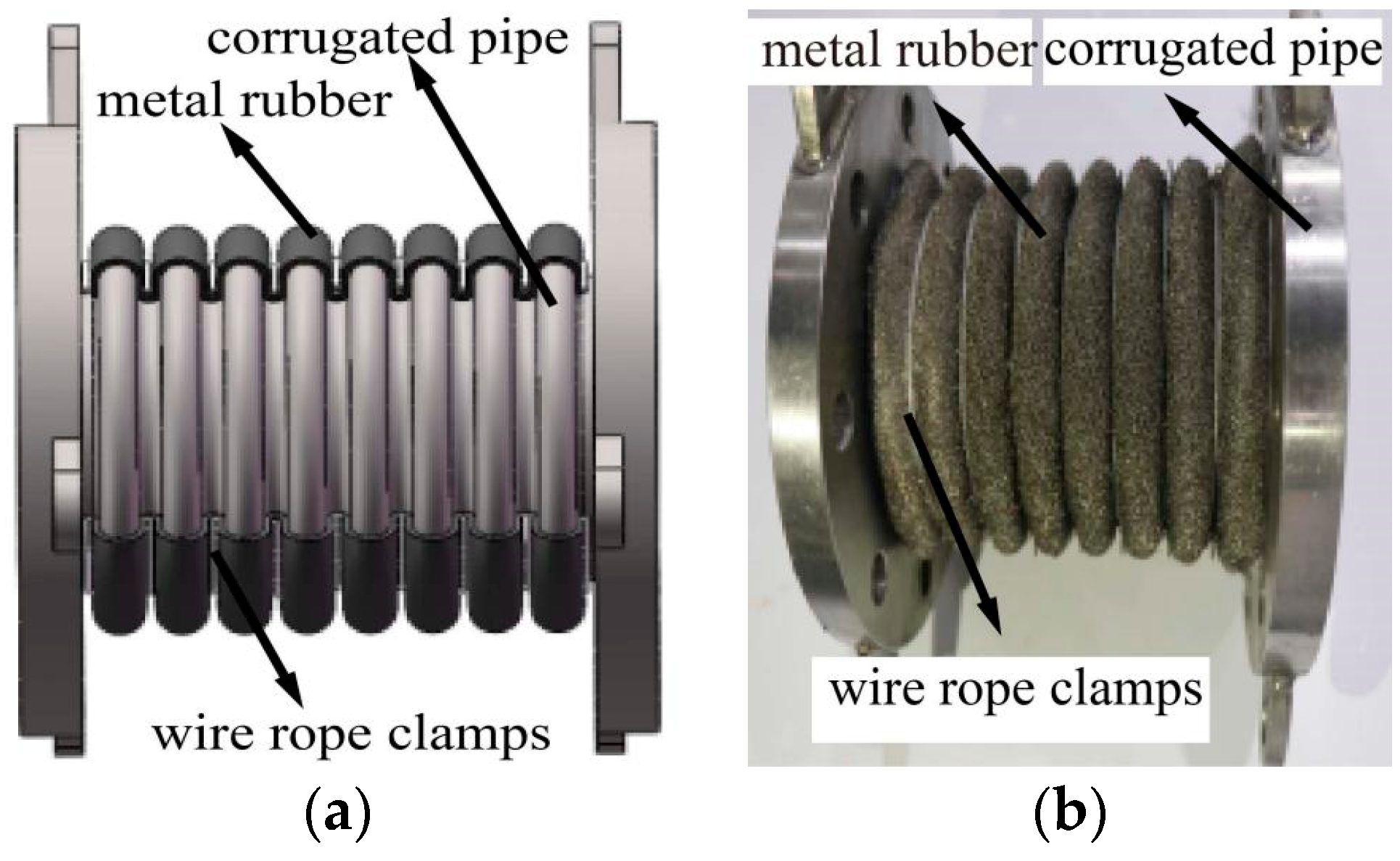
2. Design of the Coated Damping Structure for Metal Rubber of Bellows
3. Test Specimen and Test Design
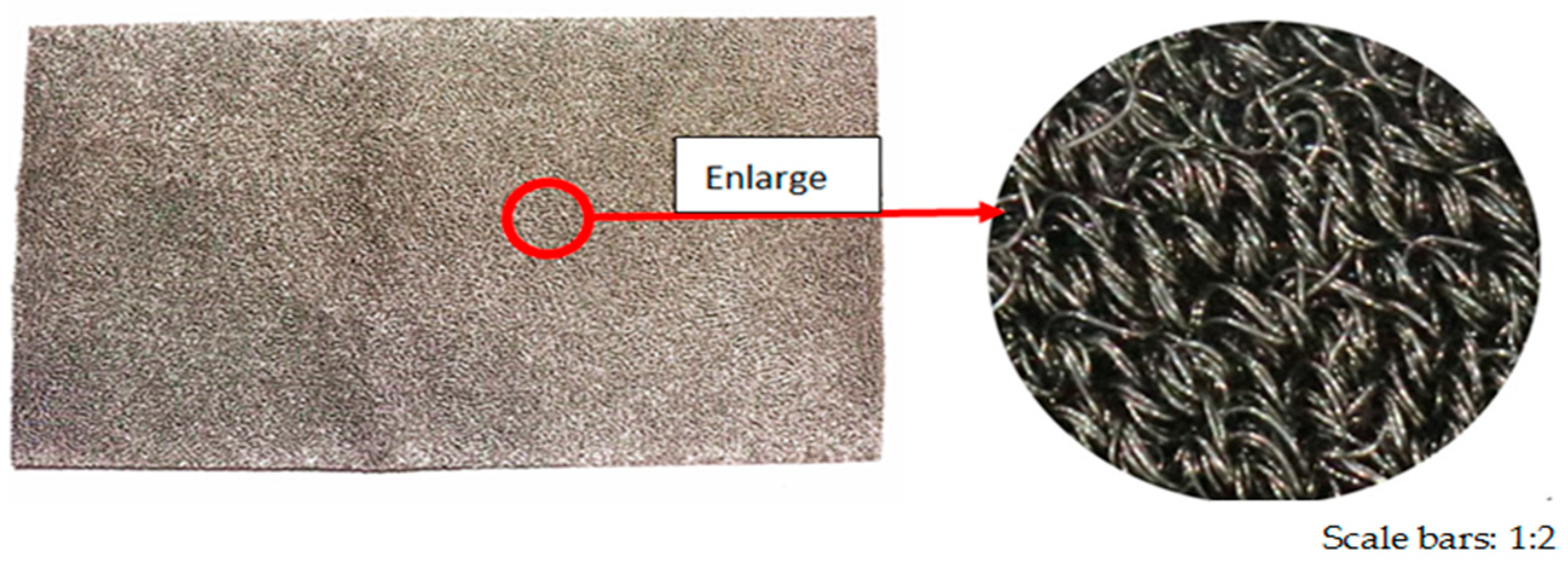
3.1. Preparation of Test Specimen and Design of Device
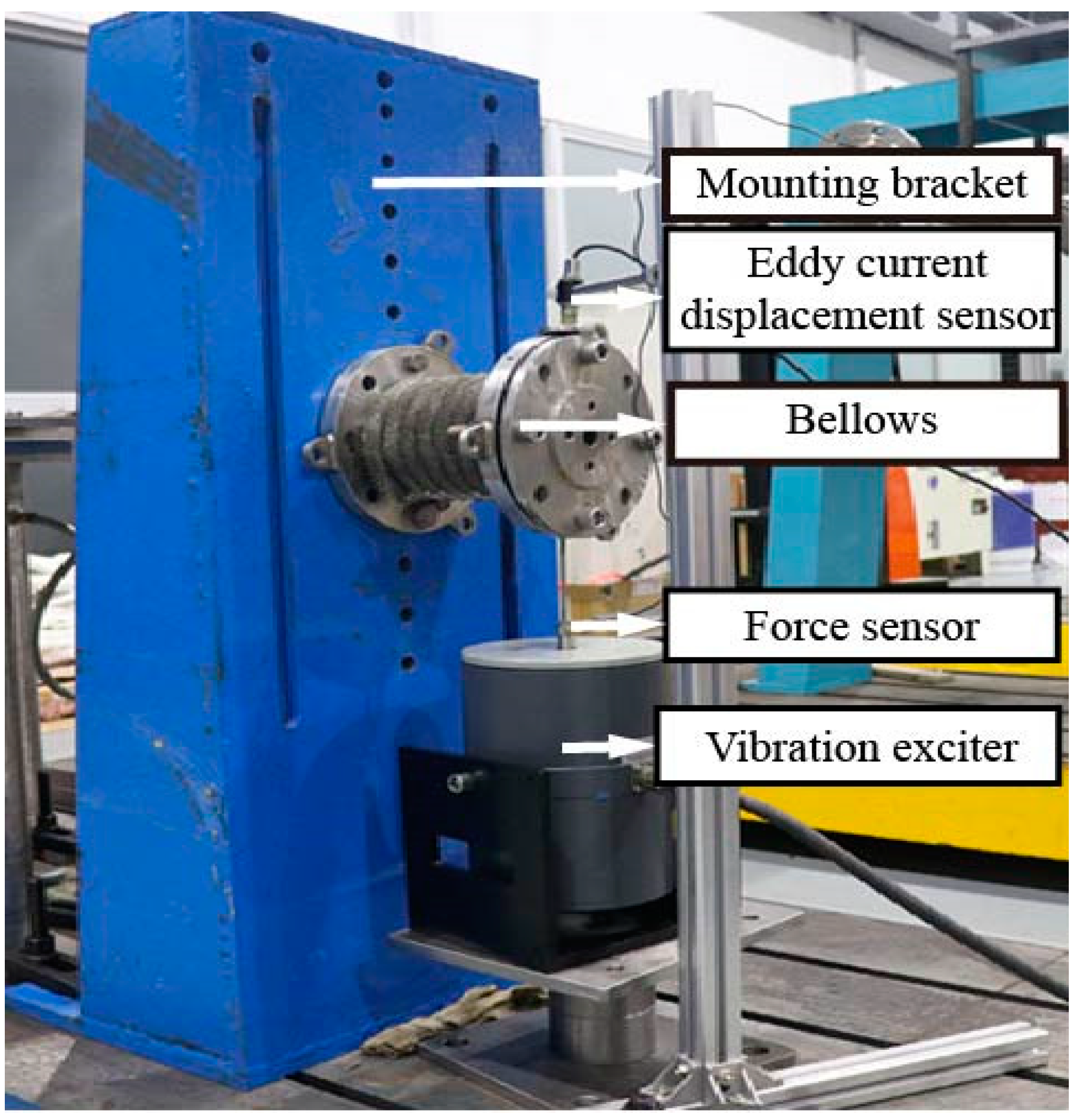
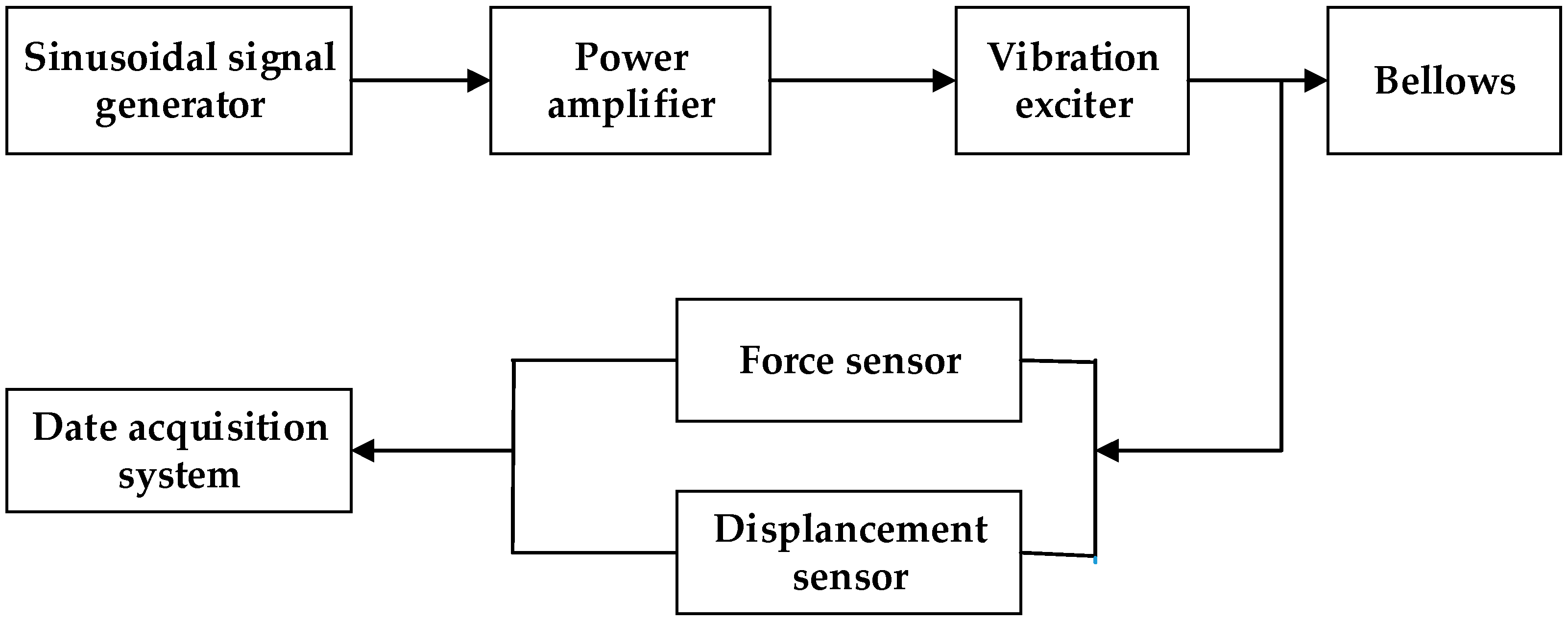
3.2. Test System and Equipment
4. Dynamic Test
4.1. Frequency Sweeping Test
4.1.1. Test Method
4.1.2. Test Results and Analysis
- (1)
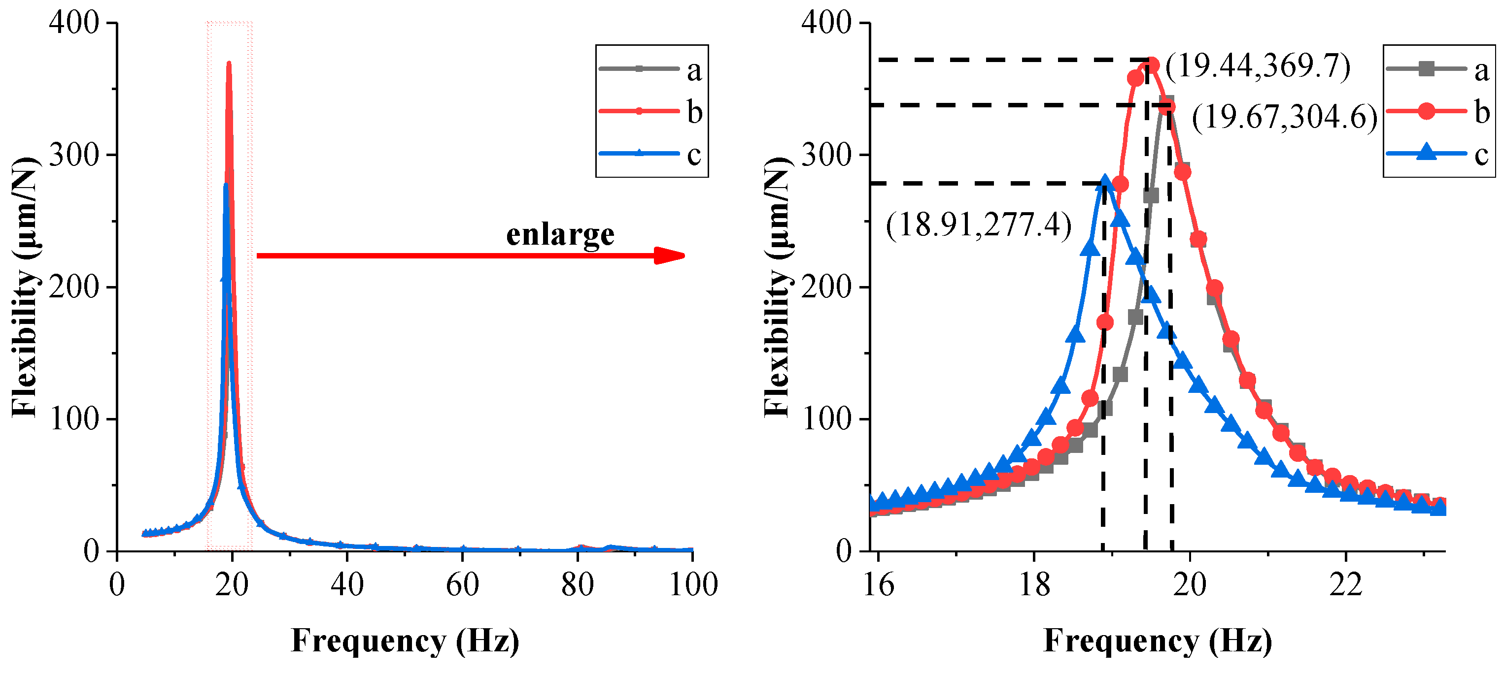
- When the exciting force was 1 N, the resonant frequency in the forward frequency sweeping test (Figure 5 (Line a)) was 19.67 Hz, and in the backward frequency sweeping test (Figure 5 (Line b)) it was 19.44Hz. It can be seen that the resonant frequency in forward frequency sweeping was higher than that in backward frequency sweeping, indicating that the frequency response curve of the coated damping structure for metal rubber of bellows bent and jumped. The bending and jumping of the frequency response curve indicate that the coated damping structure for metal rubber of bellows contained a high-order nonlinear elastic restoring force.
- (2)
- When the exciting force was 3 N, the resonant frequency in the forward frequency sweeping test (Figure 5 (Line c)) was 18.91 Hz, and the flexibility was 277.4 μm/N. When the exciting force was 1 N, the resonant frequency in the forward frequency sweeping test (Figure 5 (Line a)) was 19.67 Hz, and the flexibility was 340.6 μm/N. It was found that the resonance peak of the sweeping curve drifted towards low frequencies, and the height of resonance peak was reduced at a high exciting force. This indicated that the increase of exciting force order led to a stiffness reduction and damping energy dissipation enhancement of the coated damping structure for metal rubber of bellows.
4.2. Damping Energy Dissipation Test
4.2.1. Test Method
4.2.2. Test Results and Analysis
5. Modelling and Parameter Identification
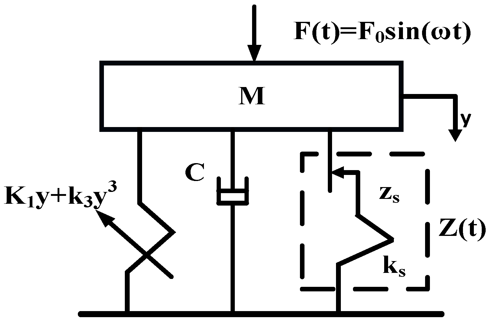
5.1. Modelling
5.2. Parameter Identification
6. Conclusions
- (1)
- Large-size metal rubber sheets were prepared, and a novel coated damping structure for metal rubber of bellows was designed. In the dynamic experiment, it was found that when the bellows expands, bends, and torsionally deforms, the metal rubber and the bellows were closely attached, and the metal rubber followed the bellows to have a good deformation effect.
- (2)
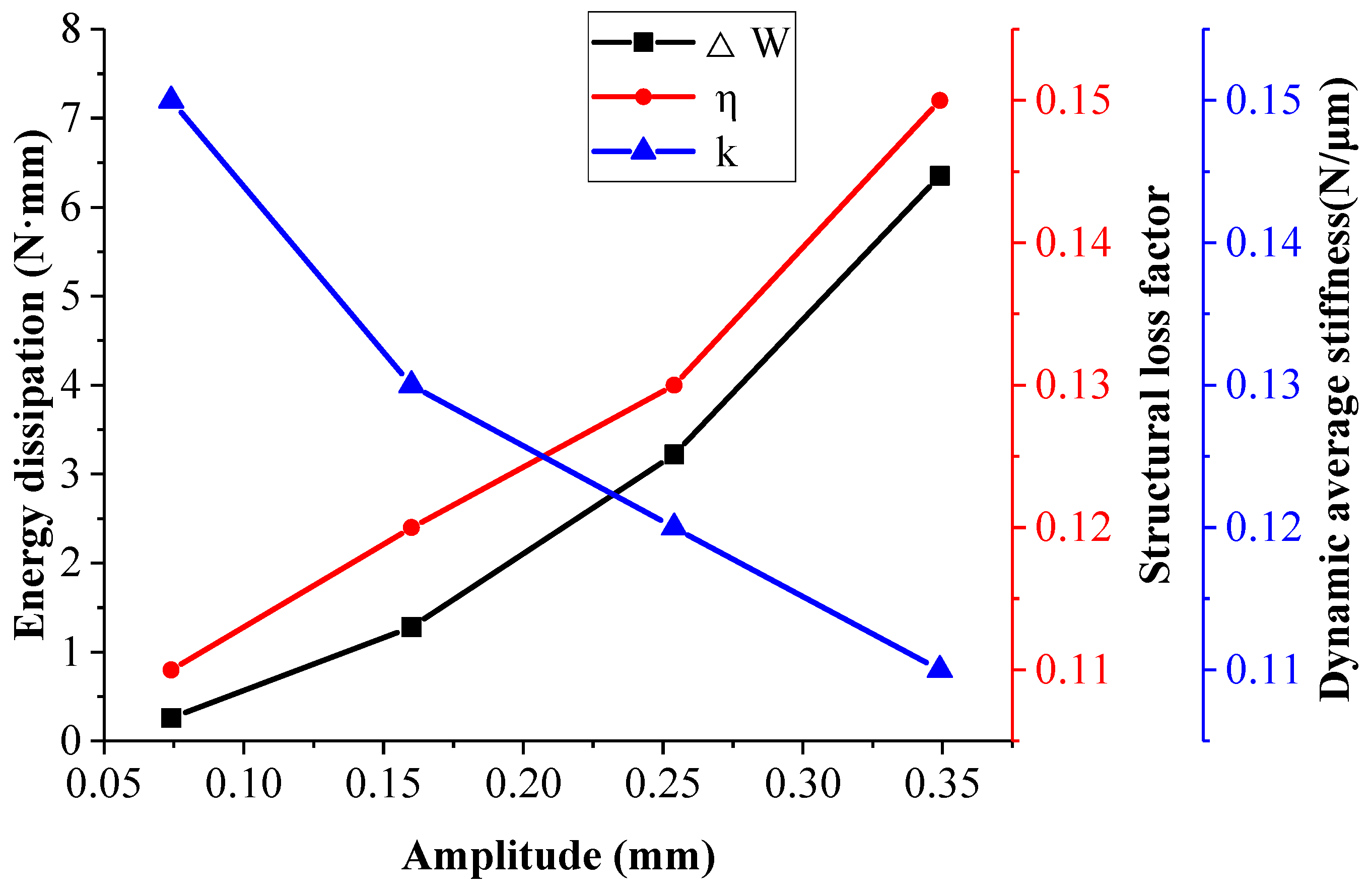
- Under all the test conditions, the structural loss factor of the coated damping structure for metal rubber of bellows was greater than 0.1, which proved that the coated damping structure for metal rubber of bellows was highly capable for damping energy dissipation.
- (3)
- It also proved that the coated damping structure for metal rubber of bellows was a nonlinear hysteresis system of variable damping and variable stiffness.
- (4)
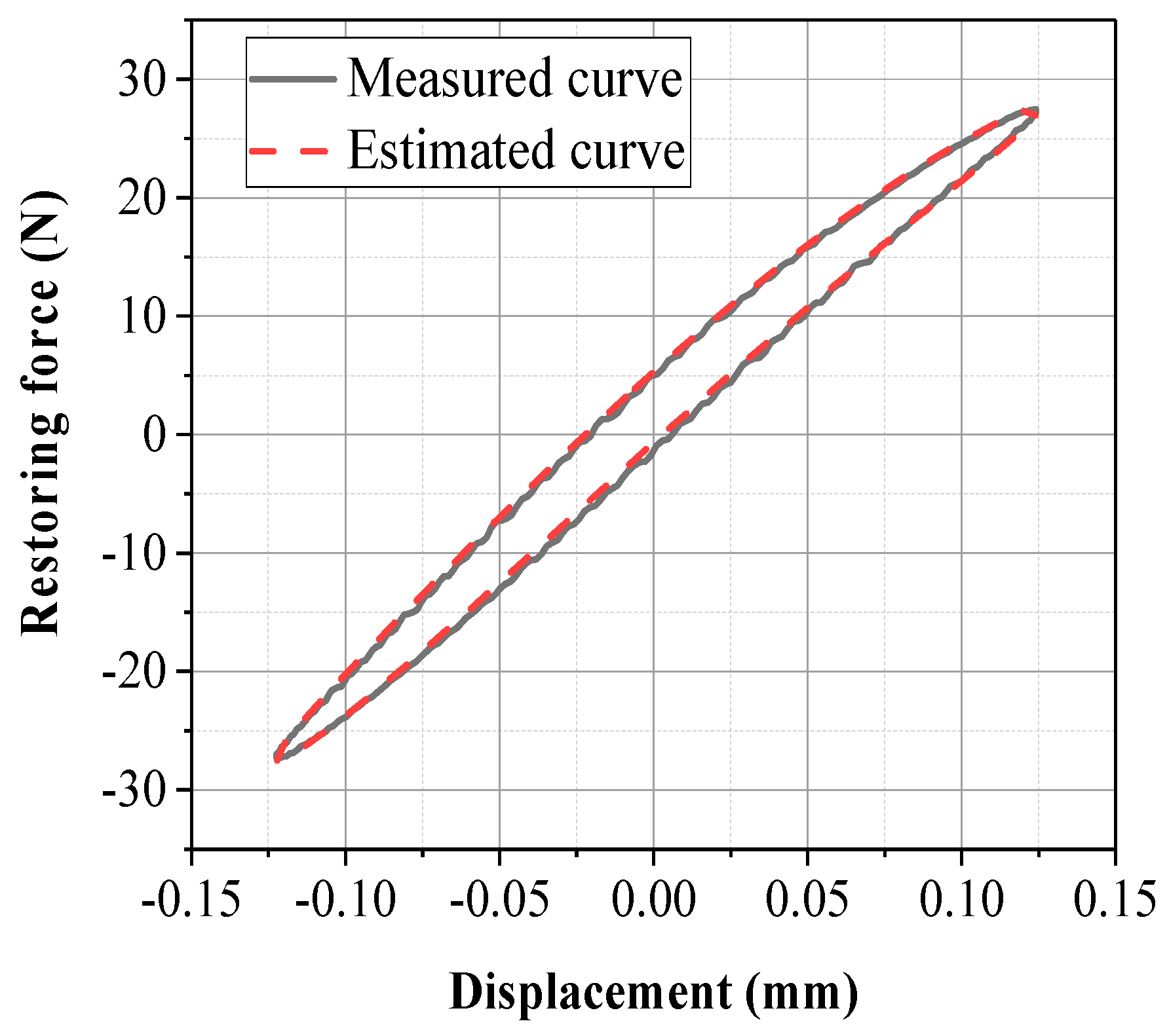
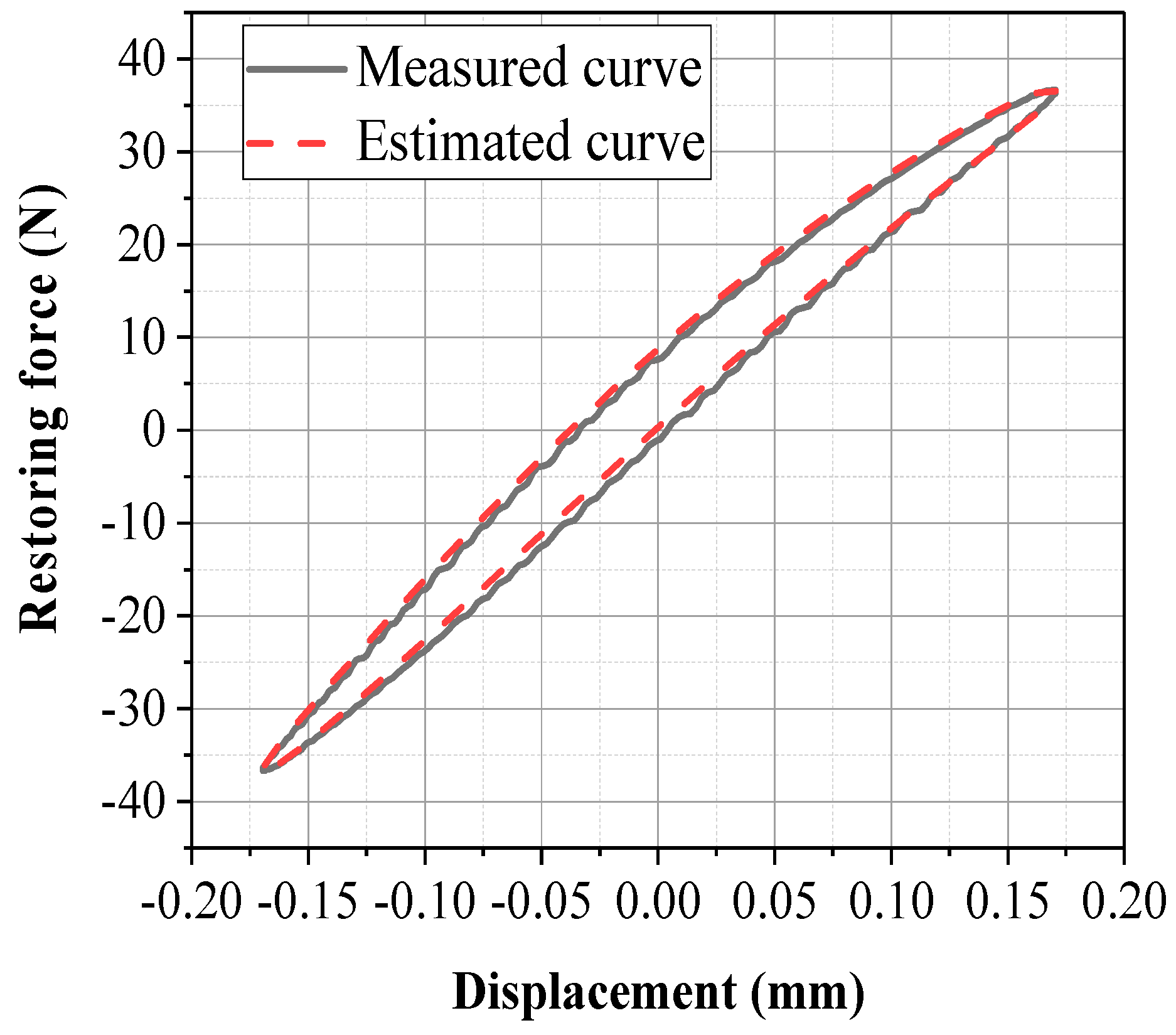
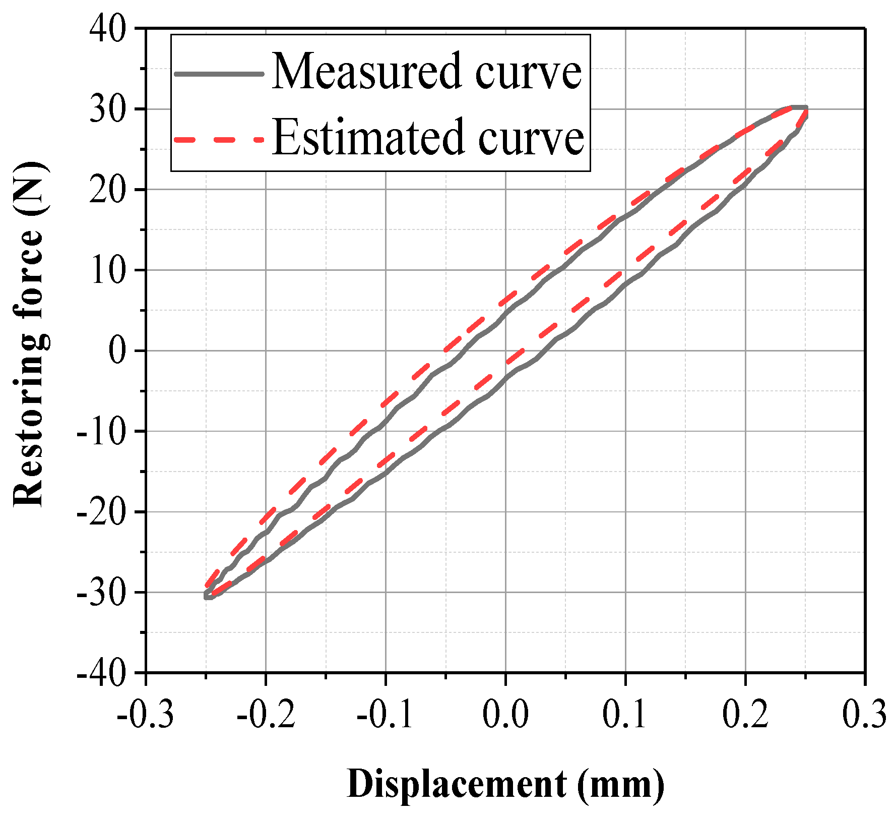
- A model of non-linear elastic restoring force was set up for the coated damping structure for metal rubber of bellows. The model was proved to properly describe the dynamic characteristics of the coated damping structure for metal rubber of bellows by parameter identification and simulation.
Author Contributions
Funding
Acknowledgments
Conflicts of Interest
References
- Ma, W.; Yu, Y.J.; Liu, Y.G.; Li, J.S.; Xue, Y.J. Simulation and experiment on the vibration performance of pre-loaded multi-plies bellows. Key Eng. Mater. 2010, 455, 476–480. [Google Scholar] [CrossRef]
- Si, D.H.; Liu, Y.G.; Ma, W. Research the influence of curved shape on the multilayer bellows. Appl. Mech. Mater. 2013, 303, 2740–2743. [Google Scholar] [CrossRef]
- Liu, Y.; Meng, H.B.; Lv, W.J. Experimental research on vibration transmission and isolation for ship’s seawater piping system. Appl. Mech. Mater. 2012, 192, 68–72. [Google Scholar] [CrossRef]
- Miao, R.; Lin, J.N. Failure analysis on cracking of DN50 stainless steel bellows. Phys. Test. Chem. Anal. 2015, 51, 136–142. [Google Scholar]
- Ma, W.; Lu, Y.V.; Liu, Y.G.; Li, J.S.; Xue, Y. Influence of sandwich damping on the loss factor of multi-plies bellows. Appl. Mech. Mater. 2010, 44, 2998–3002. [Google Scholar] [CrossRef]
- Liu, Y.G. Research on stiffness and damping of sandwich damping metal bellows considering fluid-solid interaction. J. Mech. Eng. 2014, 50, 74. [Google Scholar] [CrossRef]
- Zhao, P.; Ma, W.; Yu, Y.J.; Yang, M.H. Research on the influencing factors of dynamic stiffness of multilayer bellows. Press. Vessel Technol. 2012, 29, 11–15. [Google Scholar]
- Liu, Y.G.; Si, D.H.; Ma, W.; Yu, Y.J.; Xie, J.F. Research on the stiffness and damping of multi-layer metal bellows with interlayer damping under fluid-solid coupling. J. Mech. Eng. 2014, 50, 74–81. [Google Scholar] [CrossRef]
- Xie, Z.; Sebald, G.; Guyomar, D. Temperature dependence of the elastocaloric effect in natural rubber. Phys. Lett. A 2017, 81, 2112–2116. [Google Scholar] [CrossRef]
- Sakulkaew, K.; Thomas, A.G.; Busfield, J.J.C. The effect of temperature on the tearing of rubber. Polym. Test. 2013, 32, 86–93. [Google Scholar] [CrossRef]
- Bai, H.B.; Lu, C.H. Metal Rubber Material and Engineering Application; Science Press: Beijing, China, 2014; pp. 123–126. [Google Scholar]
- Ma, Y.H.; Tong, X.L.; Zhu, B.; Zhang, D.Y.; Hong, J. Theoretical and experimental study on thermo-physical properties of metal rubber. Proc. Phys. 2013, 62, 470–479. [Google Scholar]
- Hou, J.F.; Bai, H.B.; Li, D.W.; Wang, Y.Y.; Tao, S. Experimental research on damping performance of metal-rubber shock absorber in high and low temperature environment. J. Aeron. Mater. 2006, 26, 50–54. [Google Scholar]
- Lin, Z.; Li, G.Z.; Bai, H.B.; Lu, C.H. Corrosion behavior and damping performance of metal rubber in simulated marine environment. Mater. Test. 2014, 38, 69–73. [Google Scholar]
- Rongong, J.A.; Goruppa, A.A.; Buravalla, V.R.; Tomlinson, G.R.; Jones, F.R. Plasma deposition of constrained layer damping coatings. Proc. Inst. Mech. Eng. Part. C J. Mech. Eng. Sci. 2004, 218, 669–680. [Google Scholar] [CrossRef]
- Paimushin, V.N.; Firsov, V.A.; Gyunal, I.; Shishkin, V.M. Identification of the elastic and damping characteristics of soft materials based on the analysis of damped flexural vibrations of test specimens. Mech. Compos. Mater. 2016, 52, 435–454. [Google Scholar] [CrossRef]
- Catania, G.; Strozzi, M. Damping oriented design of thin-walled mechanical components by means of multi-layer coating technology. Coatings 2018, 8, 73. [Google Scholar] [CrossRef]
- Lu, C.H.; Bai, H.B.; Hu, R.X. Dynamic model of metal rubber/rubber composite laminated energy dissipation device. J. Vib. Eng. 2008, 21, 493–497. [Google Scholar]
- Lu, C.H.; Bai, H.B. Experimental modeling and parameter identification of metal rubber/rubber composite laminated energy dissipation device. J. Vib. Shock 2007, 26, 5–8. [Google Scholar]


| k1/(N/mm) | k3/(N/mm) | c/(N·s/mm) | zs/N | ys/mm |
|---|---|---|---|---|
| 217.0547 | 93.7498 | 1.4049 | 0.2140 | 0.0006 |
| k1/(N/mm) | k3/(N/mm) | c/(N·s/mm) | zs/N | ys/mm |
|---|---|---|---|---|
| 207.5159 | 126.6203 | 1.6700 | 0.2571 | 0.0008 |
| k1/(N/mm) | k3/(N/mm) | c/(N·s/mm) | zs/N | ys/mm |
|---|---|---|---|---|
| 121.4934 | 20.2165 | 0.4099 | 0.1627 | 0.0016 |
© 2018 by the authors. Licensee MDPI, Basel, Switzerland. This article is an open access article distributed under the terms and conditions of the Creative Commons Attribution (CC BY) license (http://creativecommons.org/licenses/by/4.0/).
Share and Cite
Wu, K.; Bai, H.; Xue, X.; Li, T.; Li, M. Energy Dissipation Characteristics and Dynamic Modeling of the Coated Damping Structure for Metal Rubber of Bellows. Metals 2018, 8, 562. https://doi.org/10.3390/met8070562
Wu K, Bai H, Xue X, Li T, Li M. Energy Dissipation Characteristics and Dynamic Modeling of the Coated Damping Structure for Metal Rubber of Bellows. Metals. 2018; 8(7):562. https://doi.org/10.3390/met8070562
Chicago/Turabian StyleWu, Kenan, Hongbai Bai, Xin Xue, Tuo Li, and Min Li. 2018. "Energy Dissipation Characteristics and Dynamic Modeling of the Coated Damping Structure for Metal Rubber of Bellows" Metals 8, no. 7: 562. https://doi.org/10.3390/met8070562
APA StyleWu, K., Bai, H., Xue, X., Li, T., & Li, M. (2018). Energy Dissipation Characteristics and Dynamic Modeling of the Coated Damping Structure for Metal Rubber of Bellows. Metals, 8(7), 562. https://doi.org/10.3390/met8070562