Corrosion, Erosion and Wear Behavior of Complex Concentrated Alloys: A Review
by
 , ,
, ,
Aditya Ayyagari
1 ,
,
Vahid Hasannaeimi
1,
Harpreet Singh Grewal
2,
Harpreet Arora
2 and
Sundeep Mukherjee
1,* 1
Department of Materials Science and Engineering, University of North Texas, Denton, TX 76203, USA
2
Surface Science and Tribology Lab Department of Mechanical Engineering, School of Engineering, Shiv Nadar University, Uttar Pradesh 201314, India
*
Author to whom correspondence should be addressed.
Metals 2018, 8(8), 603; https://doi.org/10.3390/met8080603
Submission received: 18 June 2018
/
Revised: 18 July 2018
/
Accepted: 24 July 2018
/
Published: 3 August 2018
(This article belongs to the Special Issue Complex Concentrated Alloys (CCAs) - Current Understanding and Future Opportunities)
Abstract
:There has been tremendous interest in recent years in a new class of multi-component metallic alloys that are referred to as high entropy alloys, or more generally, as complex concentrated alloys. These multi-principal element alloys represent a new paradigm in structural material design, where numerous desirable attributes are achieved simultaneously from multiple elements in equimolar (or near equimolar) proportions. While there are several review articles on alloy development, microstructure, mechanical behavior, and other bulk properties of these alloys, then there is a pressing need for an overview that is focused on their surface properties and surface degradation mechanisms. In this paper, we present a comprehensive view on corrosion, erosion and wear behavior of complex concentrated alloys. The effect of alloying elements, microstructure, and processing methods on the surface degradation behavior are analyzed and discussed in detail. We identify critical knowledge gaps in individual reports and highlight the underlying mechanisms and synergy between the different degradation routes.
1. Introduction
Development of materials having superior surface degradation resistance has been a major thrust area of research in modern metallurgy. Loss of material in the form of corrosion, erosion, and wear results in economic impact in the range of billions of dollars worldwide by some estimates. Several technologies have not realized their full potential due to the lack of materials that can withstand surface degradation in critical applications. Specific examples include core walls, diverters, and reactor vessels in nuclear reactors that can withstand hot corrosion, contact with molten metals, high-pressure water, and exposure to super critical temperatures. Similarly, there is high demand for developing materials with improved wear resistance for enhancing the energy efficiency of turbines, windmill rotors, and automobiles. These call for structural components that can withstand high torque and resist metallurgical changes that are caused by frictional heat and high pressure. Problems, such as white matter in bearings, spalling, and deterioration in mechanical properties under operating conditions remain as a major challenge. In addition, synergistic combination of different surface degradation mechanisms leads to accelerated material loss. Examples include simultaneous wear and corrosion seen in food processing and chemical handling industries. Erosion is another significant source of material loss, where particulate materials, such as sand and debris entrapped in a moving/impinging liquid, degrade the surface integrity of materials.
Traditionally, development of materials that simultaneously meet multiple application requirements has been done by adding minor proportions of alloying elements to the base material and tailoring the heat treatment. Examples include aluminum alloys, where tempering treatments are used to obtain a balance in mechanical properties and corrosion resistance. In that regard, multi-principal element alloys represent a new paradigm in structural material design, where numerous desirable attributes are achieved simultaneously from multiple elements in equimolar (or near equimolar) proportions [1,2,3,4,5,6,7]. These alloys are typically referred to as high entropy alloys (HEAs) or more generally as complex concentrated alloys (CCAs). High configurational entropy leads to single-phase solid solutions in a certain subset of these multi-component systems. It was initially believed that the core effects, such as high configurational entropy [8], lattice distortion [9], and sluggish diffusion [10] may have resulted in a gamut of attractive properties including high strength-ductility combination [6,10,11], resistance to oxidation, corrosion and wear properties [12,13]. However, recent reports suggest that these may not be the only structure-property determining parameters, thus leaving a large scope for understanding the physical metallurgy of complex concentrated alloys [14,15,16]. Another advantage of the complex concentrated approach is the vast number of alloy systems that can be developed from a small palette of elements by focusing on the central region of the multi-component phase space, rather than the edges [16].
With exponentially growing interest in complex concentrated (or high entropy) alloys, there are several reports in literature on the surface degradation behavior of these multi-component systems. The corrosion behavior of high entropy alloys has been discussed in a recent review [17]. However, a clear understanding of the underlying mechanisms and synergy between the different surface degradation routes is lacking. Here, we provide a comprehensive overview of corrosion, erosion, and wear behavior of complex concentrated alloys to elucidate the similarities and in certain cases the unique differences in response to different environments. The effect of alloying elements, microstructure, and processing methods on the different surface degradation routes are analyzed and discussed in detail.
2. Evaluation of Surface Degradation Mechanisms
In this section, the methods used in literature for evaluation of corrosion, wear and erosion behavior of complex concentrated (or high entropy) alloys are summarized along with the pertinent metrics for quantifying the extent of damage.
2.1. Corrosion Characterization
Corrosion behavior of complex concentrated alloys has been evaluated by immersion (or mass loss/gain) test, open circuit potential measurement with time, potentiodynamic polarization, and anodic polarization. Immersion test is the simplest, where the change in mass of the sample is measured by assessing the damage that is caused by the environment in which it is immersed (ASTM G31). The corrosion rate is calculated as:
where, K is a constant, T is time of exposure in hours, A is area in cm2, W is mass loss/gain in g, and D is the density in gm/cm3.
Accelerated assessment of corrosion performance can be made using electrochemical corrosion tests. When no external current or potential is applied to a metal immersed in an electrolyte, the system eventually reaches equilibrium and the net current measured is zero. The potential developed on the surface of the electrode when the metal is immersed into the electrolyte is called the open circuit potential (OCP). For potentiodynamic polarization, three types of reference electrodes are typically used, namely saturated calomel electrode (SCE), Ag/AgCl electrode, and standard hydrogen electrode (SHE). In a three-electrode set up, one of the aforementioned electrodes is connected as reference electrode, the sample as working electrode, and platinum or graphite as counter electrode. In the potentiodynamic polarization test, the sample is subjected to a potential sweep typically from −250 mV with respect to OCP to at least +250 mV at a scan rate of 0.16 mV/s. Scanning beyond 250 mV above OCP may cause further anodic reactions, such as breakdown of the protective surface oxides and pitting. Potentiodynamic polarization tests are extensively used to identify critical corrosion parameters such as pitting potential, passivation range, corrosion current, and re-passivation potentials in an accelerated way. Corrosion rate is calculated as:
where, K is 3.27 × 10⁻³ mm g/(μA·cm·year), icorr is the corrosion current density, and EW is the equivalent weight. Equivalent weight is calculated from the expression:
where, fi is the mass fraction, wi is the atomic weight, and ni is the valence of the ith element in the alloy [18].
2.2. Wear Testing
The wear behavior of complex concentrated alloys has been evaluated using three techniques, namely sliding reciprocating wear test, pin on disc test, and modified pin on disc test (pin-on-belt test). The fundamental working principle is the same in all three tests—a normal load is applied on to a sample while it is in contact with a reference material. Depending on the test type, either the reference material or the sample are moved to cause a relative motion between the surfaces. In pin-on-disc and pin-on-belt tests, the sample is made into the form of a stationary cylinder called “pin”, which is brought in contact with a rotating disc made of hardened steel. A test load is applied normal to the pin, producing wear at the interface of the two materials as shown in Figure 1a. The rotating steel disc may be replaced with a moving belt, typically coated with Alumina or Silica abrading media, as shown in Figure 1b. In the sliding reciprocating test, the sample is made in the form of a flat plate and loaded under a hard counterface, such as WC or Si3N4 ball indenter or steel pin, as shown in Figure 1c. The stage slides at a set frequency and stroke length. The wear volume loss is quantified while using weight loss, contact profilometry, or interferometry.
Quantification of loss during wear test is done from the volume of worn material removed (Vw) and relating it to total sliding distance (L) and load (F). Wear volume loss for most engineering materials increases with decreasing hardness, as given by Archard’s relation:
where, K is the dimensionless wear coefficient and H is the hardness. Certain high entropy alloys followed the Archard’s wear relation in sliding wear test. The engineering unit of wear resistance is measured as wear volume loss per unit distance of sliding and expressed in the dimensions of [L]/[L]3.
2.3. Erosion and Erosion Corrosion Characterization
Erosion is a form of material degradation characterized by the progressive loss of material from a solid surface due to mechanical interaction between the surface and a fluid or impinging liquid containing solid particles. There are very limited number of reports on erosion behavior of complex concentrated (or high entropy) alloys. Erosion that is caused by the impact of solid particles entrained in gaseous medium is termed as solid particle erosion. On the other hand, if a liquid is used as a carrier medium, the process is termed as slurry erosion [19,20]. The impact of the entrained abrasive particles results in micro-cutting and severe plastic deformation of the target surface depending on the operating parameters (Table 1). Other forms of erosion, which result from the interaction between a solid surface and fluid alone, are cavitation erosion and liquid droplet erosion [21,22,23]. In the case of cavitation erosion, degradation takes place due to implosion of cavities/bubbles in the liquids. Implosion of such cavities results in the formation of high velocity micro jets or shockwaves affecting the solid surfaces. Contact pressures at the point of impact can reach several hundred Giga-Pascals, which is sufficient for the deformation and removal of material. Several parameters influence the erosion processes, which may be classified into flow related, erodent related, and materials related parameters (Table 1) [24,25,26,27,28]. Chemical/electrochemical interactions (corrosion) are also possible along with erosion depending on the working environment. The synergy between erosion and corrosion can further aggravate the material degradation. The synergistic effect in tribo-corrosion process due to interaction between erosion and corrosion is given as [25]:
where, S is the synergy, W is the material removal rate by combined erosion and corrosion process, E is the material removal rate by pure erosion process, and C is the material removal rate by pure corrosion process. The synergy, S, is further composed of: (1) erosion induced corrosion (ΔCE) and (2) corrosion induced erosion (ΔEC). The factors that are responsible for erosion-induced corrosion are increase in surface area due to roughening effect, increased strain hardening and dislocation density, mechanical damage of the passive layer, and increased local temperatures. The factors contributing towards corrosion-induced erosion may be dislodgement of hard particles due to corrosion of the matrix, weakened grain boundaries, inter-granular pitting, and accelerated cracking due to crevice corrosion.
3. Corrosion Behavior of Complex Concentrated Alloys
Majority of the complex concentrated alloys studied so far for their corrosion behavior are based on the CoCrFeNi equimolar system. The observed corrosion behavior in these alloys may be broadly classified based on their composition and the resulting surface passivation layers, microstructural heterogeneity, phase segregation and associated galvanic corrosion, and finally, the test environment. CoCrFeNi-Cux (where “x” indicates varying proportions) was one of the earliest developed alloys, where the effect of increasing copper content on the microstructure and corrosion properties was reported [29]. Immersion and potentiodynamic polarization tests were conducted in 3.5 wt% NaCl solution. The as-cast CoCrFeNi-Cux alloys showed face centered cubic (FCC) phase mixture having distinct dendritic (copper lean) and inter-dendritic (copper rich) phases. In this alloy, the bright inter-dendritic regions were Cu rich as shown in Figure 2a. The X-ray diffraction (XRD) results show a single set of FCC peaks for several of these compositions, although the microstructure shows segregation between dendrites. This may be due to the very close d-spacing of the two phases that could not be resolved in XRD. The corrosion behavior of these alloys was comparable to SS304 stainless steel, with the copper free composition showing highest resistance to pitting (Figure 2b). The x = 0.5 alloy showed higher corrosion current density and pitting density, as shown in Figure 2c. This was attributed to higher galvanic action prompted from the Cu segregated in the inter-dendritic regions. Galvanic coupling results in initiation and propagation of localized corrosion pits causing rapid dissolution of the more anodic phase (in this case the bright Cu rich phase).
The effect of Al addition to CoCrFeNi has also been systematically studied and the resulting microstructure and corrosion behavior has been reported [30]. The Al0.1CoCrFeNi alloy shows a single-phase FCC structure with good microstructural stability. The XRD patterns for the alloy in recrystallized and as-cast state are shown in Figure 3a,b, respectively. The corresponding SEM microstructures are shown in Figure 3c,d.
The corrosion behavior of Al0.1CoCrFeNi has been reported in as-cast and recrystallized states in 3.5 wt% NaCl solution [31,32]. The corrosion behavior of the alloy was superior to SS304 steel as seen in Figure 4a. The corrosion potential, corrosion current density, and pitting resistance (referred to as EBD in [32]) were comparable between as-cast and recrystallized states for Al0.1CoCrFeNi alloy. Minor variations between reported values in literature may be explained based on the microstructural differences between as-cast and recrystallized samples. Surface finish also plays an important role in determining the corrosion behavior. Potentiodynamic polarization for Al0.1CoCrFeNi alloy was compared with another single phase HEA, CoCrFeMnNi, as shown in Figure 4b. Both alloys showed wide passivation region and transient pitting, which may be an indication of local corrosion and the re-passivation on the surface.
The pitting resistance (ΔE) or breakdown resistance (EBD) of Al0.1CoCrFeNi alloy measured as the difference of pitting potential (EPIT) and corrosion potential (ECORR) in both conditions was ~1 V. Transient pitting was observed in both conditions around 0.6 V (highlighted with circle on the polarization curve), which may be an indicator of localized surface instability. More events of transient pitting were seen for the as-cast condition as compared to the recrystallized sample, which may be explained from the microstructural heterogeneity. Both as-cast and wrought alloys showed a high passivation resistance, 193 kΩ [31] and 115.5 kΩ [32], respectively, when tested for their EIS response. The superior corrosion resistance of Al0.1CoCrFeNi alloy has been explained based on the relatively high content of Cr and Ni that form a strong passivating surface layer. Pitting resistance is typically quantified based on the wt% of passivating elements that are present in the alloy. Particularly, Cr, Mo, and Ni enhance pitting resistance of most engineering alloys. Since CCAs have passivating elements as high as 20%, are reported to have excellent pitting and corrosion resistance, provided that there are no extraneous corrosion promoters, such as galvanic phases or physical surface aberrations. Al0.1CoCrFeNi high entropy alloy showed unique corrosion microstructures, as shown in Figure 5. Corrosion was initially observed to occur in the form of tiny pits, as shown in Figure 5a. Unique hierarchical features developed as a result of extensive grain boundary corrosion as well as micro/nano porosity formation within the grains, as shown in Figure 5c,d.
The effect of increasing Al content on the corrosion behavior of AlxCoCrFeNi alloy system was investigated in sulfuric acid [33] as well as in NaCl solution [34]. Besides the effect of alloying elements, the effect of experimental variable, i.e., scanning rate and temperature of the alloys in the corrosive media was also studied. This is an important metric to be systematically studied since scan rate can significantly alter the values of corrosion rate measured [33,34]. Increasing Al content induced microstructural changes to Figure 7. Pitting morphology hat significantly affected the corrosion behavior. The single phase FCC alloys for x = 0, x = 0.25, and x = 0.3 were more corrosion resistant when compared to the alloys containing higher fraction of Al. This was primarily attributed to phase separation induced by increasing Al content. Figure 6a shows secondary passive region for alloys with x = 0.5 and x = 1.0, which was attributed to the selective corrosion of dual phase face centered cubic (FCC)–body centered cubic (BCC) alloy (for x = 0.5) and BCC-ordered structure (for x = 1.0). In comparison, Figure 6b shows the potentiodynamic polarization charts for alloys with x = 0.5 and x = 0.7, displaying multiple transient pitting sites and continuous corrosion, both of which indicate the corrosion of secondary phases and partial passivation behavior of the matrix.
The single phase FCC alloys for x = 0 to 0.3 in AlxCoCrFeNi system showed significantly lower pitting density and pit depth when compared to the two phase alloys resulting from higher Al content. The x = 0.5 alloy showed pits on the inter-phase boundary between the FCC and BCC phases, indicating the formation of a galvanic couple. For x = 0.7 and x = 1.0, the BCC phase was observed to significantly/completely dissolved in H2SO4 solution and NaCl solution. Increasing Al content promotes the formation of BCC phase in AlxCoCrFeNi alloys, which undergoes selective dissolution. Increasing Al content likely results in the formation of porous Al oxide on the surface at the expense of more compact and passivating Cr oxide. A clear pattern of evolution of pitting morphology is seen as the Al content in gradually increased. Al = {0.1–0.3}: uniform pitting → Al = {0.5}: interphase galvanic corrosion → Al = 0.70–1.0 complete dissolution of BCC phase. Therefore, increasing the Al content beyond a threshold value resulted in higher pitting susceptibility, as seen in Figure 7.
Heat treatment of Al0.5CoCrFeNi alloy resulted in phase separation and formation of BCC + FCC phases from a single-phase parent FCC cast alloy [35]. The overall corrosion resistance of the alloy was lower when compared to SS304 steel. Corrosion morphology on the single-phase FCC phase alloy comprised mostly of hemispherical pits nucleating randomly on the surface. This is an indicator of no preferred pit initiation site, while the hemispherical morphology indicates an equal propensity for pit to propagate into the material (Figure 8a). No dendritic coring or secondary pitting was seen. However, in contrast, the alloy with FCC + BCC phases showed preferred pitting along the interphase boundary. This is a clear indication of galvanic coupling between the two phases, governed by composition difference and the partitioning of elements between the two phases. Figure 8b shows the random pitting morphology preferentially occurring along the grain boundaries of the two phases.
In addition to intrinsic chemistry and crystal structure, melt-solidification history was found to affect corrosion resistance of CCAs [36]. Understanding the effect of re-melting on the microstructure and consequent corrosion properties can help in casting alloys with superior chemical homogeneity and properties. A multicomponent AlCoCrFeNiTi alloy was prepared by induction melting in Ar atmosphere. The alloy was subsequently re-melted several times in order to homogenize the distribution of elements. The re-melting may have eliminated macro-segregation arising from incomplete melting of elemental metal chunks used in alloy making. However, this may not have completely eliminated micro-segregation in the form of coring. This was evident in the form of a dendritic microstructure with micro-segregation in the inter-dendritic areas. The dendrites were rich in Al, Co, Ni, and Ti, while the inter-dendritic regions contained a higher fraction of Fe and Cr. The microstructure consisted of BCC phases along with complex intermetallics such as AlFe3. Despite the complex microstructure, the corrosion performance of the alloy was better than SS410 alloy. The addition of Ti improved the corrosion rate of the alloy (0.0216 mm/year) by almost a factor of four compared to the Ti-free alloy (0.08 mm/year). This improvement may have resulted from the complex surface oxides that promote strong passivation. Re-melting the alloy homogenized the microstructure by removing macro-segregation, which contributed to improved corrosion resistance.
With increasing interest in the additive manufacture of these complex alloys, the first step is to be able to process the alloys using power-technology. The corrosion behavior of AlCoCrFeNi alloy system was studied as a function of Cu addition via the powder metallurgy route. The corrosion properties were evaluated in 1 mol/L NaCl [37]. The alloy produced using powder metallurgy route showed a microstructure that is similar to the conventional casting route. Microstructure of the AlCoCrFeNi–Cu alloy after sintering is shown in Figure 9a. The microstructure was complex and showed a two phase-mixture of FCC + BCC phases. The potentiodynamic polarization curve for this alloy is shown in Figure 9b. The corrosion potential was −0.012 V and the corrosion current density was 3.23 nA/cm2. The alloy did not show any pitting up to potentials as high as 1.5 V versus saturated calomel electrode (SCE). This observation is insightful since powder-technology route was observed to possess improved corrosion resistance compared to conventional melt route. This may have resulted from the fact that powder particles individually possess oxide on the surface that are retained when the compacted is sintered. The larger surface oxide present on the bulk of the material may have imparted a nobler corrosion resistance as compared to its fused counter parts. The highly symmetric pattern seen in Figure 9a may have its origins in the parent (oxide covered) powder particles that explains the improved corrosion resistance that is seen in Figure 9b.
Increasing B content led to the precipitation of boride containing phases as seen in Figure 10a–d [38]. The corrosion behavior of the alloys was tested in 1 N H2SO4 [39]. The corrosion current density of the alloy increased from 787 µAmps/cm2 to 2848 µAmps/cm2 with the increase in boron content and boride phase fraction. The increasing boride phase fraction promoted the formation of “stringy precipitates” rich in Cr, Fe, and Co borides. This difference in composition led to the formation of local micro galvanic couples, making them susceptible to corrosion, as seen in Figure 10e–h. The phases rich in strongly passivating elements (Cr, Co) showed high pitting resistance while the matrix and inter-dendritic regions preferentially corroded. The morphology of the secondary phase changed with progressively increasing B content. Increasing B promoted stronger phase separation and formation of anodic regions that corroded more aggressively. The precipitation of hard boride phases may improve other surface properties, such as hardness and wear resistance (as discussed in subsequent sections), but certainly deteriorated the corrosion resistance due to galvanic corrosion. A balance of mechanical degradation resistance and galvanic corrosion resistance must be achieved by properly tailoring the composition to suite the application requirements.
The corrosion behavior resulting from addition of Cr and Ti to the base composition of AlCoCuFeNi has been reported and corresponding microstructures are shown in Figure 11a–d [40]. The bright phase in the images is Cu-rich FCC, whereas the BCC phases are rich in Al and Ni and they show a darker contrast. Adding Cr resulted in the formation of dendrites, whereas BCC formed into lamellar Widmanstatten type structures. Ti caused Al-, Co-, Ni-, and Ti-rich BCC phases (A2/B2), whereas adding both Cr and Ti refined the grain structure and led to copper segregation. The corrosion behavior of the alloys studied in 0.5 mol/L H2SO4 solution showed very low corrosion current densities—in the range of 5–8 μA/cm2 for the Cr containing alloy. In contrast, the Ti and Ti-Cr containing alloys showed much higher corrosion activity. Cr and Ti typically improve corrosion resistance. The anomalous finding in this study may be due to the heterogeneous microstructure of the alloy that resulted in the formation of micro-anode and micro-cathode regions that accelerated corrosion. The corroded microstructures are shown in Figure 11e–g, indicating that the Cu-rich FCC phase was highly susceptible to corrosion. Corrosion of Cu-rich phases may be due to the higher galvanic character of the alloy, thus making it susceptible to dissolution.
In contrast to adding passivating elements, such as Cr and Ti, in the aforementioned study, the effect of changing corroding species, such as Cu and Al content on mechanical and corrosion behavior was studied for AlxCoCrCu0.5FeNi system [41]. The corrosion resistance of this alloy was studied in 0.5 M H2SO4 and 0.5 M NaCl solution. The x = 0.5 alloy showed single-phase FCC structure, while alloys with x = 1.0 and x = 1.5 showed a mixture of FCC and BCC phases. The microstructure of the two-phase alloys was a BCC-rich dark matrix and light inter-dendritic FCC phase, as shown in Figure 12a. Potentiodynamic polarization curves showed that the alloys with two-phase microstructure had lower corrosion resistance due to the formation of micro-galvanic couples. NaCl environment caused pitting, while the alloy showed passivation behavior in H2SO4 solution. Solutionizing heat treatment improved the corrosion resistance of the x = 1.5 alloy as the FCC phase dissolved leaving behind a largely BCC alloy. The potentiograms in Figure 12b,c show the alloys’ behavior in 0.5 M NaCl and 0.5 M H2SO4 solution.
The pitting corrosion resistance of CoCrFeNiTiMox was evaluated as a function of Mo content, varying from x = 0 to x = 0.8 [42,43]. The corrosion behavior was tested in acidic, basic, and saline solution. The as-cast microstructures of CoCrFeNiTiMox are shown in Figure 13a–d. Increasing Mo content altered the microstructure to result in phase-partitioning—a dark dendritic phase and a bright interdendritic (ID) phase. Mo was observed be uniformly distributed between the two phases at 0.1 at%, however, increasing the Mo content partitioned in to the interdendritic (ID) regions. This may be due to the strong single-phase forming tendency of Co-Cr-Fe-Ni system, as established by various studies. While the average composition of Co, Cr, Fe, and Ti varied by a mere 2–4% between the two regions, Ni content variation between the dendritic and interdendritic phase was as high 50%, as measured by EDS. A broad observation is that the interdendritic region is rich in Mo and lean in Ni. This information in conjunction with individual binary phase diagrams of Mo and Co, Cr, Fe, Ti, (elements in the ID region), and enthalpy of mixing values suggests that the σ phase that is formed in the alloy might not be a simple Mo-Cr phase, akin to SS316L. The changing phase composition and partitioning of elements between dendritic and ID regions may have resulted in galvanic coupling and the consequent increased corrosion of Mo containing alloys as compared to Mo free/lean alloys.
The corrosion behavior by immersion test was studied for two CCAs, namely, CrCu0.5FeMnNi and Cr0.5CuFeMnNi [44]. The as-cast microstructure of the two alloys are shown in Figure 14a,d. Both of the alloys showed dendritic microstructure with FCC or FCC + BCC solid solution phases. The corrosion behavior of the alloys was characterized by an immersion test and potentiodynamic polarization in 1 M H2SO4. The microstructures after immersion test are shown in Figure 14b,e, while that after accelerated corrosion are shown in Figure 14c,f. Both tests showed preferred corrosion of the inter-dendritic phase due to galvanic coupling from the partitioning of alloying elements. Superior corrosion resistance of the dendritic phase was explained by the passive layers of NiO, Ni(OH)2, NiSO4, and Cr2O3. The corrosion resistance of both the alloys was superior to stainless steel. Between the two alloys, the one with lower Cu content showed lesser elemental segregation and higher corrosion resistance.
Complex concentrated (or high entropy) alloys have been synthesized in the form of coatings by several processing routes, including melt cladding and deposition, chemical vapor deposition (CVD), physical vapor deposition (PVD), electro spark processing [45], direct current magnetron sputtering [46], and laser cladding techniques [47]. Surface clad CCAs showed a desirable microstructure because of rapid solidification, good metallurgical bonding to substrate, and lesser compositional segregation [48,49]. In the form of coating, CoCrFeMnNi CCA showed spontaneous passivation in NaCl solution. Although this CCA coating showed icorr value similar to 304SS, the passivation potential window for 304SS being wider. The CCA showed better corrosion resistance than 304SS in H2SO4, with a stable passive film formation. The initiation of corrosion for CoCrFeMnNi coating started with the depletion of chromium between the dendrites, and the subsequent weakening of the microstructure.
Addition of Ti up to a certain percentage to AlCoCrFeNi CCA coating resulted in better corrosion and cavitation erosion performance in NaCl [28]. Further increase in Ti content resulted in the formation of Ti2-Ni and NiAl intermetallic compounds and decreased the passivation resistance. The alloy with the highest Ti content showed the worst corrosion resistance. Cavitation erosion behavior is primarily dictated by mechanical strength of a material in a non-corrosive medium. Therefore, the coating with the highest Ti content showed improved cavitation erosion resistance in distilled water, because the intermetallic compounds acted as a deformation barrier on the surface. In contrast, the same alloy (highest Ti content) showed the worst cavitation resistance in NaCl solution due to the synergistic effect of cavitation and corrosion in NaCl medium. Interestingly, AlCoCrFeNi coating without Ti showed remarkable cavitation erosion resistance, better than 304 stainless steel in NaCl with a lower icorr value [50]. Ti addition up to a certain percentage to Al2CrCoCuFeNiTix coating fabricated by laser cladding resulted in good corrosion performance in HNO3 [51]. Ti promoted the formation of a BCC phase in this CCA coating and affected both the corrosion and wear properties. Due to rapid cooling rates that were achieved during laser cladding, lesser segregation and uniformly refined grains (down to nanoscale) were reported [52]. The homogenous microstructure resulted in better corrosion resistance. Addition of Ti to AlCoCuFeNi CCA produced by arc melting resulted in a two-phase heterogeneous microstructure and micro-anode/cathode regions in the electrolyte [53]. The corrosion resistance was found to decrease for this alloy at both 298 K and 366 K in H2SO4. Laser processed AlCoCuFeNi CCA coating showed similar corrosion current densities to the coatings containing Ti [40,54]. The improvement in corrosion performance was attributed to the reduced dilution rate and formation of a compact CCA phase by controlling the laser parameters. Niobium also showed a similar effect as Ti in CCA coatings. The addition of Nb prevented less noble elements from dissolving in corrosive environments [54]. Corrosion performance of CoCrCuFeNi CCA coating increased considerably with the addition of Nb due to modification of microstructure and the formation of a very stable passive film [55]. Addition of Nb reduced the Cu segregation in interdendrite regions, resulted in the formation of a finer FCC phase and very stable surface oxide films.
Al addition up to a certain percentage showed improved corrosion current density for AlxCoCuFeNi CCA coating made by laser cladding [56]. A monotonic increase in corrosion resistance was reported for AlxCoCrFeNiTi [57]. A similar trend was observed for addition of Ni to Al2CoCrCuFeNixTi laser cladded CCA coating [58]. Increasing Ni content in this CCA coating, with x values up to 2, resulted in better corrosion performance in NaOH and NaCl solutions. In summary, the presence of corrosion resistant elements, such as Cr, Ti, Al, and Ni in limited quantity improved corrosion resistance in CCA coatings. However, beyond a certain mole fraction, microstructural segregation and lattice distortion led to a worsening of corrosion resistance.
The presence of Co in CCA coatings typically resulted in improved corrosion performance. In some CCA coatings, Co formed a passive film of CoO, which after exposure to corrosive medium, formed Co(OH)2 [59]. Co(OH)2 acted as a protective passivation layer and prevented corrosive species, such as Cl− and O2−, from diffusing into the coating. AlCoCrCuFe-X0.5 CCA coating in which X was Si, Mo, and Ti, showed no passivation in NaCl [60]. In addition, extensive pitting was observed for the alloy containing Mo and Ti on the Cr-depleted Fe2Mo and Fe2Ti phases, as shown in Figure 15. However, the dendritic regions enriched with Cr remained passivated after polarization tests.
The electrochemical behavior of CCA coatings has been reported to be different from their bulk counterparts with identical chemical composition [18,61,62]. Due to rapid cooling rates, CCA coatings possess more homogenous microstructure with lesser elemental segregation. In contrast, bulk as-cast HEAs typically consist of dendrites and inter-dendritic regions with different chemical compositions, resulting in micro-galvanic cells that accelerate the corrosion process. This effect was clearly demonstrated for AlCoCrFeNi CCA coating fabricated through electro-spark method. Relatively uniform corrosion was seen for the coating (Figure 16a), while a non-uniform attack was seen for the as-cast alloy (Figure 16b). The inhomogeneous corrosion of the cast CCA was attributed to the micro-galvanic coupling between the matrix precipitates and the matrix itself. However, the CCA coating was free from intercellular segregation and precipitates.
Direct current magnetron sputtering has also been used for the fabrication of CCA coating with a uniform and homogenous microstructure consisting of very fine grains and low levels of segregation. Coatings fabricated via this method typically showed amorphous microstructure at initial stages of deposition, which crystallized with the increase in deposition time. AlCoCrCuFeMn CCA coating fabricated by magnetron sputtering with a thickness of 1–2 µm showed better corrosion resistance than 201 stainless steel in NaCl, NaOH, and H2SO4, with a wide passive region due to fine grains and limited segregation in the microstructure.
Overall, the corrosion resistance of several CCAs are reported to be comparable or better than stainless steels. This may be attributed to the larger fraction of constituent elements, such as Co, Cr, and Ni in the alloy that improve the pitting resistance and improve passivation. Addition of copper was found to induce phase separation and formation of galvanic couples. Vast majority of CCAs reported so far have corrosion potential between −200 to −400 mV and corrosion current density less than 2 µAmps/cm2 as summarized in Figure 17. The corrosion current density is lower than stainless steels although corrosion potentials are comparable. Another metric for evaluating the corrosion behavior is the pitting resistance (ΔE), measured as the difference between corrosion potential and pitting potential. The pitting resistance of several CCAs are compared with stainless steels in Figure 18. Some CCAs show two times higher pitting resistance when compared to stainless steel. Table 2 is a summary of reported CCAs, their microstructure, corrosion environment, and type of polarization along with the major finding in each case.
The overall corrosion behavior of CCAs was observed to be dependent on three major factors. First, the composition of the alloys—this in turn affects the nature of the passivation layers, and the relative galvanic characteristic of the constituent phases; second, the environment in which corrosion is being evaluated; and third, the processing parameters. Most of the CCAs investigated showed better corrosion resistance as compared to stainless steels. This is primarily due to the high content of elements that form a passivating oxide layer. For example, SS316 has ~18% Cr, ~12% Ni, and ~2% Mo. In contrast, most of the CCAs that are made of equimolar proportions have at least 20% Cr, 20% Co, and 20% Ni, all of which provide strong passivating effect that translates into better corrosion resistance. Further, the HEA subset showed high resistance to uniform corrosion since these alloys form a single phase structure devoid of galvanic coupling. The general observation of lowering of corrosion resistance with multi-phase CCAs is in line with the galvanic series of alloys. Cu was observed to be particularly detrimental in several of these alloys since it is not only anodic with respect to the passivating elements, but also precipitated in the form of secondary phases that acted as the preferred corrosion sites. No particular relationship between the crystal structure (FCC or BCC) and corrosion resistance was observed. However, phase mixtures had lower corrosion resistance when compared to isomorphous systems. Intermetallic phases, such as borides, aluminides, and Nickel Titanates acted as corrosion initiation sites. The matrix region around the intermetallics dissolve due to anodic character that cause the particles to dislodge. Rupture of passive layer promotes rapid dissolution of the underlying alloy and associated material degradation. Similar effects were observed in Al, B, Mo, and Ti; however, the extent of deterioration varied significantly. Phase morphology was also found to play an important role. Secondary phases with needle and plate-like features dissolved more rapidly when compared to uniformly distributed equiaxed phases, likely because of unfavorable anode to cathode ratio at the tips.
The test environment and corroding species determined the electrochemical kinetics. In general, Cl− containing solutions caused more corrosion damage as compared to acidic or alkaline solutions. There are limited reports on in vitro and in vivo corrosion studies for bio-medical applications. Processing parameters affect the microstructure, which in turn affects the corrosion behavior of CCAs. Powder processing route was observed to produce more corrosion resistant alloys due to homogeneous elemental distribution, whereas lower corrosion performance was seen in alloys that were produced via melt-casting routes due to coring and segregation. There are significant knowledge gaps on the response of CCAs to welding and joining treatments and associated weld-induced sensitization.
4. Erosion and Erosion Corrosion of CCAs
There are very limited number of studies on the erosion behavior of CCAs/HEAs. The two alloy systems that have been studied the most are AlxCoCrFeNi and AlxCoCrCuFeNi. Slurry-erosion behavior of Al3CrCoFeNi laser cladded CCA was compared with conventionally used 17-7 precipitation hardened (PH) stainless steel. The Al3CrCoFeNi CCA coating showed excellent erosion resistance when compared to 17-7 PH stainless steel with seven times higher resistance at 15° impingement angle [71]. Maximum erosion rate for both CCA and 17-7 PH steel were observed at 45° impingement angle. Thereafter, the erosion rates were more or less constant with a further increase in impingement angle. Higher erosion resistance of the Al3CrCoFeNi CCA was due to high hardness (~750 HV) of the BCC phase and severe lattice strains. Significant lattice distortion was attributed to the high mole fraction of large sized Al atom. The effect of heat treatment on erosion behavior of Al3CrCoFeNi CCA coating was also investigated. Increased erosion resistance (~15% compared to untreated HEA) was seen with increase in annealing temperature with maximum corresponding to the 950 °C heat-treated sample. Authors attributed the enhanced erosion resistance of the CCA coating treated at 950 °C to increased hardness (765 HV), resulting from Cr3Ni2 precipitation and reduced roughness.
In AlxCoCrFeNi alloy system, decrease in Al content results in transition from pure BCC to BCC + FCC and finally to pure FCC structure [72]. Al0.1CoCrFeNi alloy shows a single-phase solid solution of face centered cubic (FCC) structure with good thermal stability. Slurry erosion behavior of Al0.1CrCoFeNi CCA was evaluated at different impingement angles (30° to 90°) and a constant impact velocity (20 m/s). Despite the low hardness of 150 HV, the cast Al0.1CrCoFeNi alloy displayed erosion resistance that is comparable to or better than mild steel (of hardness 205 HV) at acute angles (Figure 19a). At normal impingement, Al0.1CrCoFeNi showed much better erosion resistance when compared to mild steel, which was attributed to the significant work hardening ability of the alloy. Continuous impact of abrasive particles during the erosion test results in significant work hardening of the HEA due to its low stacking fault energy and nano-twin formation [73]. The stacking fault energy (SFE) for Al0.1CrCoFeNi high entropy alloy is reported to be about 30 mJ/m2 [74]. However, Al0.1CoCrFeNi alloy showed lower erosion resistance when compared to stainless steel SS316L due to higher hardness and strength of the later. Correlation with different mechanical properties showed that the ultimate strength and ultimate resilience significantly affected the erosion behavior in these multi-component metallic systems.
The slurry erosion-corrosion behavior of AlCrCoCuFeNi CCA after annealing at different temperatures (600 °C and 1000 °C) was studied [27]. Both untreated and heat-treated AlCrCoCuFeNi alloy showed high erosion resistance compared to SS304 stainless steel. Untreated AlCrCoCuFeNi alloy also showed higher corrosion resistance compared to SS304 stainless steel. However, sample annealed at 600 °C showed significantly reduced corrosion resistance, which was attributed to precipitation of intermediate phases. Further increase in annealing temperature improved corrosion resistance from the resulting microstructural homogeneity. In contrast to corrosion studies, the combined erosion-corrosion test showed distinctly different behavior for the sample annealed at 600 °C, exhibiting the lowest mass loss. The improvement in erosion-corrosion resistance was predominantly due to increased hardness (~500 HV) due to the formation of ordered B2 or disordered A2 structures from the annealing process. Addition of higher Al fraction in the AlCrCoCuFeNi system was observed to increase hardness due to the formation of BCC/B2 structure and improved erosion-corrosion resistance. However, lowering the Al content improved the corrosion behavior [34]. The Al0.1CrCoFeNi HEA showed high slurry erosion-corrosion resistance (~1.8 times higher) as compared to SS316L stainless steel with significant negative synergy, as shown in Figure 19b. The negative synergy for Al0.1CrCoFeNi CCA indicates the positive contribution of corrosion in lowering the mass loss during the erosion-corrosion test. The Al0.1CrCoFeNi CCA also showed high pitting and protection potentials as compared to SS316L steel, indicating the formation of stable passive layer. Stability of the passive layer was partly attributed to the high mixing entropy resulting in high activation energy for diffusion.
Ti addition was found to enhance the corrosion and cavitation erosion resistance of complex concentrated alloys [28]. Cavitation erosion-corrosion behavior of laser cladded AlCrCoFeNiTix CCA (x = 0.5 to 2) was evaluated. Maximum cavitation erosion resistance was observed for AlCrCoFeNiTi2 HEA. However, the trend reversed completely for the cavitation erosion-corrosion test, with AlCrCoFeNiTi2 CCA showing the least resistance. This trend reversal was explained by the formation of Ti2Ni and NiAl intermetallic compounds. These intermetallics significantly enhanced the hardness and reduced erosion rates due to increased resistance to plastic deformation. At the same time, formation of intermetallic compounds degraded the corrosion resistance due to the formation of localized galvanic cells and unstable passive layer.
The cavitation erosion-corrosion performance of AlCrCoFeNi laser cladded CCA was compared with 304 stainless steel [50]. The AlCrCoFeNi coating showed 7.6 times better cavitation erosion-corrosion resistance compared to 304 stainless steel. The better performance of the CCA was attributed to combined effect of high hardness and corrosion resistance. The high hardness resulted from the BCC solid solution and corrosion resistance from the homogeneous microstructure without any intermetallic phases. When compared to Epit of 96 mV observed for SS304 steel, AlCrCoFeNi laser cladded CCA showed significantly high pitting potential of 257 mV indicating higher passive layer stability of the later.
Al0.1CrCoFeNi alloy showed remarkable resistance to cavitation erosion and erosion-corrosion compared to 316L stainless steel as shown in Figure 19c [76]. Additionally, the alloy showed a much longer incubation period of 6.5 h as compared to 2.5 h for 316L stainless steel. This was attributed to comparatively greater degree of work hardening and superior corrosion resistance of Al0.1CrCoFeNi alloy. The strain hardening exponent for Al0.1CrCoFeNi (n = 0.77) was more the two times that of the 316L stainless steel (n = 0.3). Higher strain hardening increased the incubation period and lowered the erosion rates by effectively increasing the flow stresses. Superior erosion-corrosion resistance of the alloy may also be explained by its higher pitting potential (Epit = 490 mV) and protection potential (Epp = 184 mV) when compared to SS316L (Epit = 359.8 mV; Epp = −10.58 mV).
Scanning electron microscopy (SEM) images of Al0.1CrCoFeNi alloy and 316L stainless steel after slurry erosion and cavitation tests under identical conditions are shown in Figure 20 [26,76]. The SS316L steel and Al0.1CrCoFeNi CCA both showed ductile mode of erosion in slurry and cavitation erosion. In the case of slurry erosion, micro-cutting and ploughing were the prominent material removal mechanisms observed at oblique angles. For normal impingement, material removal was mainly through formation and removal of platelets (platelet mechanism). When compared to micro-cutting, the material removal for Al0.1CrCoFeNi alloy at an oblique angle was mainly through ploughing mechanism due to higher ductility as compared to SS316L steel. In addition, few micro-indents were also observed for samples that were tested at 90°. Micro-indentation resulted in severe plastic deformation and the removal of the strained material once accumulated strain reached a critical value [77]. From the cavitation erosion-corrosion test, the formation of craters and pits were observed as the primary damage mechanism (Figure 21). The size of the craters were significantly larger for SS316L steel, while they were virtually absent for the CCA as seen in Figure 21. High ductility and strain hardening for Al0.1CrCoFeNi alloy played an important role in limiting crack formation/propagation and material loss.
Complex concentrated alloy coatings have also been studied for their erosion behavior [28,45,78,79,80,81]. AlxCrCoFeNi (x = 0.1 to 3) CCA coatings were developed using microwave processing on SS316L steel substrate, with microstructure consisting of intermetallic phases, as shown in Figure 22 [82]. The matrix in these coatings was composed of either FCC or BCC phases depending on the Al fraction. The average micro-hardness showed a direct correlation with Al fraction in the coatings. The average hardness for Al0.1CrCoFeNi coating was 438 HV, which was significantly higher when compared to the bulk counterpart, which is mainly due to the difference in microstructure [26]. Maximum hardness of 624 HV was obtained for Al3CrCoFeNi CCA coating. Slurry erosion studies of these coating showed a significantly higher erosion resistance at an oblique impingement angle (30°) when compared to SS316L steel. The maximum erosion resistance was observed for the equimolar composition. However, for normal impingement all of the coatings showed an increase in erosion rate indicating brittle behavior. The increase in erosion rate at normal impingement was attributed to the brittle intermetallic σ and B2 phases. Lowest erosion rate observed for the equimolar AlCrCoFeNi CCA coating at both acute angles and normal impingement was attributed to the combination of higher hardness resulting from the secondary phases and fracture toughness. SEM image of the slurry eroded CCA coating that was tested at 90°shows the presence of large craters for the non-equimolar compositions as shown in Figure 22. The cracks resulted in disintegration of the secondary phase, which is most prominent for Al3CrCoFeNi. In contrast, the equimolar composition showed lesser tendency for brittle fracture.
A comparative analysis of cavitation erosion and erosion-corrosion behavior of CCAs with respect to conventional structural materials [28,50,83,84,85,86,87] is shown in Figure 23 in terms of the mean depth erosion rates (MDER). For both of the test conditions, CCAs show much lower MDER compared to conventional alloys, such as stainless steels. Therefore, the use of CCAs in applications demanding high erosion and erosion-corrosion resistance can effectively improve the durability and service life of the susceptible components.
The existing literature provides a fair understanding on the erosion and erosion-corrosion behavior of AlxCrCoFeNi-X high-entropy alloy systems. There is a large scope for investigation of erosion-corrosion behavior of alloys for several other compositions with high hardness and corrosion resistance. The alloys in the AlxCrCoFeNi-X system tend to have higher erosion-corrosion resistance as compared to stainless steels, which may be due to the higher content of passivating elements. The studies reported so far have investigated the room-temperature properties of the alloys. However, critical knowledge gaps exist for high-temperature erosion-corrosion behavior. For example, boiler tubes are susceptible to extreme conditions and high temperature erosion-corrosion. In addition, the synergistic effects in cavitation erosion and slurry erosion due to the presence of corrosive media need to be investigated for better understanding of degradation in marine environments. Biofouling behavior of HEAs is another area for future research with high impact.
5. Wear Behavior of CCAs
All of the complex concentrated (high entropy) alloy systems that have been studied so far for their wear behavior are summarized in Figure 24. They are broadly classified based on the alloy chemistry and processing. In addition to wear behavior, the hardening response, phase stability, and hot hardness was reported for some alloys. The copper containing alloys were typically single phase or mixture of two simple phases. The copper free alloys were based on AlCoCrFeNi system and modified with Ti or Mo. The copper free alloys showed higher wear resistance when compared to the copper containing alloys. In addition, wear behavior of alloys that are composed of purely refractory elements have also been reported. Surface modification was done for some conventional steels and Ti alloys by LASER cladding, tungsten inert gas (TIG), and sputtering to enhance the wear properties.
The wear behavior of AlxCoCrCuFeNi [89] alloy system has been systematically investigated by varying the Al content from x = 0.5 to x = 2. In the AlxCoCrCuFeNi cast alloys, there was Cu segregation in the inter-dendritic region, while other elements enriched the dendrites. At x = 0.5, the dendritic and inter-dendritic phases were both FCC, which changed with increasing Al content. Increasing Al content stabilized BCC phases and resulted in hardness increase by several times The Archard’s wear relation was found to hold true in the case of AlxCoCrCuFeNi alloy system with improving wear resistance from the increased hardness.
The softer composition in AlxCoCrCuFeNi system with x = 0.5 showed ductile deformation, grooving, and disc-like wear debris, as shown in Figure 25, all of which are in line with ductile character of the FCC-rich alloy. On the other hand, the BCC-rich alloys showed smoother surface deformation, finer wear debris that were enriched with oxygen, indicating oxidative wear. The steady state friction value was the lowest for Al0.2CoCrCuFeNi, which is in line with the surface oxidation and high hardness that protected the alloy from tribo-degradation. Based on variation in hardness, ductile deformation, and steady state friction values in AlxCoCrCuFeNi alloy system, the Al0.5CoCrCuFeNi composition was chosen for further modification. Addition of V to Al0.5CoCrCuFeNi alloy resulted in a phase mixture consisting of FCC, BCC, and sigma phase [90]. Fixing aluminum content at 0.5 and gradually increasing V content increased the BCC phase fraction. The change in microstructure with increasing V mole fraction is shown in Figure 26. Increasing the vanadium concentration increased BCC phase fraction and hardness of the alloy, but this did not translate into improved wear resistance. There was marginal increase in wear resistance even though the hardness increased from 200 HV to a peak hardness of ~650 HV. The optimum composition range for enhanced mechanical and tribological properties was in the range of 1.0 to 1.2 mole fraction of Vanadium. Therefore, multiple competing factors affected the wear behavior, including complex microstructure, elemental segregation, BCC phase fraction, and morphology.
Boron is known to be a BCC phase stabilizer in ferrous alloys. In contrast, this effect was not seen with boron addition to Al0.5CoCrCuFeNi. The alloy retained its FCC structure when B was less than 10%, while small quantities of ordered FCC phases evolved when the content was increased to ~15% [38]. In contrast to Vanadium addition, changing B content led to a significant strengthening effect. Addition of boron to the AlCoCrCuFeNi system was observed to increase the hardness and wear resistance of the alloy to 736 HV and 1.76 m/mm3, respectively. The wear resistance of the alloy was superior when compared to wear resistant SUJ bearing steels. Hardness increased from ~300 HV to 750 HV along with nearly doubling of wear resistance when boron content was increased from 0% to 15%. The changes in hardness and wear resistance with the addition of Vanadium, Boron, and Aluminum are summarized in Figure 27.
The CoCrFeNi alloy system has been shown to be very versatile in terms of compositional and microstructural modifications. Addition of Ti results in the formation of Ni3Ti intermetallic compounds that impart exceptional high temperature strength. Therefore, high entropy forming CoCrFeNi composition may be significantly strengthened by these intermetallic phases. Extensive studies have been done to understand the competing effects of Al and Ti in the AlxCo1.5CrFeNi1.5Tiy system by creating a series of alloys [91]. Al-free Co1.5CrFeNi1.5Ti0.5 and Co1.5CrFeNi1.5Ti1.0 alloys were developed for isolating the effect of Ti, while Al0.2Co1.5CrFeNi1.5Ti0.5 and Al0.2Co1.5CrFeNi1.5Ti1.0 were developed to identify the effect of Al.
Addition of Ti1.0 improved the hardness by about 100 HV when compared to the Ti0.5 bearing alloys. Addition of Al caused slight drop in hardness due to suppression of (Ni,Co)3Ti formation. The overall hardness of Al0.2Co1.5CrFeNi1.5Ti1.0 improved by over 200 HV as compared to Al free counterparts. Among the four alloy systems Al0.2Co1.5CrFeNi1.5Ti1.0 showed highest wear resistance, being as high as 5500 m/mm3, which is nearly double the values on the other alloys. The tribological properties of the alloys can be compared to commercial wear resistant steels, such as SUJ2 and SKH51. As far as the mechanisms are concerned, the softer alloys displayed characteristic features of wear on ductile materials, such as delamination, grooving, and plastic deformation, as shown in Figure 28. The degradation mechanism for the high Ti content alloys was predominantly oxidative wear in the tribo-system, shallow wear tracks, and marks on the surface. These oxide layers typically protect the underlying alloy from meta-metal contact, thereby reducing adhesive wear. Although the tests were conducted at room temperature, the contact temperature during wear may rise to temperatures where softening and oxidation may be of concern. Therefore, high temperature hardness is important in these applications. Unlike other alloys derived from the CoCrFeNi base system, the AlCoCrFeNiTi alloy forms high temperature deformation resistant intermetallic particles. These particles effectively improve the alloy performance and contribute to improved tribological properties.
Al and Ti promoted the formation of ordered phases and had a significant effect on the hardness and wear resistance of alloys. Extensive microstructure characterization was done and wear behavior was studied for the Al0.25CoCrFeNiTi0.75 alloy [92]. The Al0.25CoCrFeNiTi0.75 alloy was seen to have a Cr-Fe-Co rich phase, a Chi (χ) phase with BCC structure, a Ni2AlTi based L21 ordered phase, and FCC minor phase. A scanning electron microscopy image of the alloy along with the EDS elemental maps is shown in Figure 29. The EDS maps showed that the lighter contrast phase is chi (χ) phase, the darker contrast phase as the FCC based ordered phase, and the greyish phase as disordered FCC. This is distinct from the Al0.2Co1.5CrFeNi1.5Ti1.0 alloy that showed blocky complex η-(Ni,Co)3Ti phase with needle like morphology. The hardness of the alloy was also observed to be around 570 HV for the (L21) phase, while, lighter contrast matrix regions showed a hardness of 1090 HV. Comparatively, these values are lower than the Al0.2Co1.5CrFeNi1.5Ti1.0 that showed η phase with Widmanstätten structures having a hardness of 1200 HV, and an overall hardness of 717 HV. The wear behavior of the alloy when tested in sliding reciprocating mode showed long grooves running parallel to the wear track. The wear tracks were shallow, with little to no surface oxidation. The wear behavior of the alloy followed Archard’s relation. Between the two phases, the softer dark phase composed of Al-Ti-Ni was observed to wear off preferentially. The size of the wear tracks increased with increasing test load. These features are shown in Figure 30. The Al0.2Co1.5CrFeNi1.5Ti1.0 was reported to have improved wear resistance than commercial high hardness wear resistant steels, such as SUJ2 and SKH51 (~65 HRC), whereas the wear performance of Al0.25CoCrFeNiTi0.75 CCA was more comparable to SS 440C (~55 HRC).
The wear behavior of high entropy alloys in marine conditions was evaluated for CoCrFeNiMn and Al0.1CoCrFeNi alloys. Here, isolating the effects of wear and corrosion that are acting simultaneously on the sample are important. Such problems can be approached by individually assessing the wear in dry condition, corrosion using electrochemial or immersion tests, and comparing the results to marine wear tests. A weighted summation of material loss from each of the wear tests would reveal the predominant mechanism of material loss between the competing mechanisms. In the case of CoCrFeNiMn and Al0.1CoCrFeNi alloys, the synergy between wear and corrosion was observed to be negative—implying that corrosion did not aggravate material loss in the alloys. Material loss during marine wear was lower than the summation of dry wear loss and material loss from corrosion [31]. The wear tracks imaged using white light interferometry (Figure 31a,b for dry and Figure 30g,h for wet conditions) show higher wear volume loss on the CoCrFEMnNi alloy in dry and marine condition. High magnification images confirm micro-grooving on CoCrFeNiMn, while spalling and fatigue wear on the Al0.1CoCrFeNi alloy. The Al0.1CoCrFeNi alloy showed lower wear loss in both dry and wet test conditions (Figure 31c,d for dry and Figure 31i,j for marine condition). Parallel grooves in the wear track indicate two body or three body wear to be operative in the alloys.
Wear resistance of the alloys that were surveyed in this study have been plotted against the reported hardness values in Figure 32. The crystal structure of the alloys have also been marked. It can be seen that irrespective of chemistry, FCC alloys typically are softer and have lower wear resistance, followed by two-phase alloys, and highest wear resistance was seen for BCC alloys. This trend changes in case of high wear resistance materials, as shown in Figure 32b. The two-phase alloys showed significantly higher hardness and wear resistance than the BCC alloys. However, there was no significant correlation for the BCC and two-phase alloys. For example, the Al0.5CoCrCuFeNiV1.6 alloy has a hardness of 600 HV with a wear resistance of 1.1 m/mm3, whereas the AlCoCrFe1.5MoNi has a wear resistance of over 1000 m/mm3 with similar hardness values, although both of the alloys have BCC crystal structure. This implies that a materials response to sliding wear is governed by factors more than just hardness and crystal structure. These critical knowledge gaps need to be addressed in future studies. The effect of lattice distortion from complex compositions on the hardness, wear resistance and friction evolution need further investigations.
In contrast to corrosion behavior, there are limited reports on wear behavior of CCA coatings. Surface cladding was typically employed for wear performance enhancement. AlCoCrNiW and AlCoCrNiSi CCA cladded layers through gas tungsten arc welding (GTAW) showed enhanced wear resistance than AISI 1050 medium carbon steel [93]. The superior wear performance of these coatings was attributed to the strong mechanical interlocking between the dense dendrites and the matrix. During the wear test, dense dendrites can strengthen the structure and prevent plastic flow. The wear performance of AlCoCrNiW layer exceeded that of AlCoCrNiSi due to stronger mechanical interlocking and a more complex microstructure. Mechanical and wear behavior of Al0.5CoCrFe2MoNiSi CCA coating fabricated by the GTAW method were reported as a function of silicon addition [94]. Superior wear resistance of this cladding layer was attributed to the formation of strong bonds between Si and the other elements in dendritic region and nanoscale precipitation in the inter-dendritic region.
Tungsten inert gas (TIG) was also used to produce CoCrFeMnNbNi CCA coating and showed much lower wear loss when compared with AISI 304 steel due to presence of a FCC Nb-rich Laves phase with nanoscale lamellar spacing [95]. The Laves phase resisted damage during sliding and protected the coating surface from plastic deformation. CuNiSiTiZr CCA coating fabricated by vacuum arc melting showed almost 2.5 times higher hardness than TC11 (typically used in aerospace industry), and superior wear resistance due to various effects, such as solid solution strengthening, precipitation strengthening, and nanocomposite strengthening [96]. A similar phenomenon was observed when AlCrSiTiV CCA coating was deposited on Ti-6Al-4V substrate via the laser cladding technique. CCA coating showed improved wear rate as compared with the Ti-6Al-4V substrate as well as higher hardness values (Figure 33).
The high wear resistance of AlCrSiTiV CCA coating was attributed to the formation of hard intermetallic phase in a relatively ductile BCC matrix. The softer matrix limited brittle crack propagation during abrasive and adhesive wear. Plasma-spray has also been used to synthesize several CCA coatings, including AlCo0.6CryFe0.2NixSiTi0.2, AlCoCrCuFeNi, AlCoCrFeNi, CoCrFeMnNi, and AlCoCrFeNiTi [98]. The effect of temperature on the wear behavior of AlCoCrFeNiTi CCA coating has also been reported. Adhesive wear with minor abrasion was the main mechanism for AlCoCrFeNiTi coating wear at 25 and 500 °C [98]. More severe adhesive wear was observed at higher temperatures due to the decrease in hardness of the coating. At temperatures higher than 500 °C, both the morphology of wear track and mechanism changed due to oxidation processes and the softening of the coating. The main wear mechanism at 700 °C was tribo-oxidation wear with wide grooves on the wear surface. The presence of micro-cracks and pores in the coating facilitated the diffusion of oxygen at higher temperatures and it caused more accelerated tribo-oxidation wear. AlCoCrFeNiTi CCA coating showed a volume wear loss of about one-ninth of 316 stainless steel at 700 °C [12].
Thermally sprayed AlCoCrFeMo0.5NiSiTi and AlCrFeMo0.5NiSiTi CCA coatings, consisting of a BCC dendrite and a FCC inter-dendritic microstructure, exhibited very good wear resistance [12,99]. Annealed CCA coatings showed even better wear resistance with minimized weight loss. The hardness value for these coatings was lower than bearing SUJ2 and hot-die tool steel SKD61. However, their wear resistance after annealing at 800 °C was much better than these wrought steels. Laser alloying has also been used for synthesizing thicker HEA coatings with strong metallurgical bonding to the substrate [48,97]. AlCoCrCuFe CCA coating fabricated by laser surface alloying showed much better specific wear rate and lower coefficient of friction (COF) than that of Q235 steel substrate, as well as three times higher hardness. It was shown that the addition of certain elements, such as Boron to AlBxCoCrFeNi coating fabricated by laser cladding, changes the wear mechanism from adhesive to abrasive wear, as the hardness increased. A summary of wear resistance and hardness is shown in Table 3.
6. Conclusions
The number of complex concentrated (or high entropy) alloy systems being reported in recent years has exploded because of their tunable microstructures and desirable properties. Improving the surface degradation characteristics of these alloys will make them very attractive in wide ranging commercial applications. Some of the main corrosion, erosion, and wear characteristics in these emerging materials are summarized below:
- Several CCA compositions showed high corrosion resistance in terms of corrosion current density, corrosion potential and pitting resistance. This was primarily attributed to the high wt% of passivating elements, such as Co, Cr, and Ni (cumulatively as high as 40%) in several of the alloys studied.
- Precipitation of secondary phases by either addition of elements or heat treatment deteriorated the corrosion behavior of multi-phase complex concentrated alloys compared to single-phase ones. On the other hand, heat treatment and secondary phase precipitation resulted in surface hardening and improved the wear resistance and erosion characteristics of the alloys.
- Alloying elements that contributed to the precipitation of secondary phases such as B, Cu, Ti, Mo, and Al deteriorated corrosion resistance. The secondary phase precipitates resulted in galvanic corrosion and promoted materials’ degradation.
- Erosion and erosion-corrosion resistance of CCAs was superior when compared to stainless steel grades, owing to their strong passivation and relatively higher hardness.
- When compared to conventional alloys, CCAs/HEAs in many cases showed better overall corrosion and erosion resistance in different media. However, there are significant knowledge gaps with respect to surface passivation mechanisms and synergy between the different degradation routes.
- The wear resistance of some CCA compositions was significantly higher than state of the art steels, such as the SJ grades. The wear resistance varied between 0.8–2.0 m/mm3 as a function of Vanadium, Boron and Aluminum content.
- Two-phase BCC + FCC alloys and single-phase BCC alloys showed orders of magnitude higher wear resistance (~5500 m/mm3 wear resistance) when compared to single-phase FCC alloys (~1.0 m/mm3 wear resistance).
- In addition to as-cast and heat treated alloys, thermally sprayed and annealed CCA coatings showed better wear resistance with minimal weight loss when compared to structural steels.
- Certain CCA compositions demonstrated excellent marine corrosion resistance. The wear volume loss was an order of magnitude lower than mild steels.
7. Future Opportunities and Outlook
Complex concentrated alloys present a plethora of opportunities for the development of next generation materials. The scope is not just limited to bulk materials and melt-deposition coatings but also in the form of thin films and powder-metallurgy products. However, critical knowledge gaps in surface degradation mechanisms need to be assessed prior to determining the true application worthiness of these alloys. The effect of processing on surface degradation mechanisms are not well understood for welding and joining, severe-plastic deformation, and hot working. Another area with very limited number of studies includes extreme environments, such as molten/fused salts, heavy ion/neutron irradiation, and high temperatures.
Understanding the nature and chemistry of the surface passivation layer is critically important for corrosion, erosion, and wear applications. This has not been done in a comprehensive way. Surface characterization using X-ray photoelectron spectroscopy (XPS) and ultra-violet photoemission spectroscopy (UPS) could reveal valuable information about the chemistry and electronic structure of the surface passivation layer and help in fundamental understanding of the underlying mechanisms. This knowledge may be utilized to develop specific surface treatments to produce strongly passivating and non-porous oxides that can offer exceptional surface degradation resistance. Slight changes in composition (micro-alloying) or processing conditions have shown large variations in properties, compounding the complexity in analyzing these multi-component systems. In complex precipitation hardened CCAs, composition fluctuations at multiple length-scales (atomic, nano, micro) may lead to “local” effects that nucleate the breakdown of passivation layers. These effects may be captured by phase-specific corrosion and wear tests at the microstructural length-scales, including scanning electrochemical microscopy (SECM) and nano-scratch/wear tests.
There are very limited reports on the lubricity and friction behavior of complex concentrated alloys. This may be of interest in tribology for developing super-lubricity complex composition coatings. Phase-specific friction studies will provide significant insights into surface degradation from multi-body wear in multi-phase CCAs [101]. Ni free complex alloys might be attractive for biomedical applications. Evaluating in-vitro wear behavior and quantifying cytotoxicity of the wear products will significantly help in developing new biomaterials. Recently reported refractory CCAs may be attractive for highly stressed bearing applications, where high temperature wear behavior, evolution of oxide layers, kinetics of spalling, and pesting are of significant fundamental interest.
Advanced additive manufacturing, LASER melt-deposition, and combinatorial development using powder bed and powder feed techniques for CCAs hold tremendous potential towards meeting long-standing challenges like highly corrosion resistant surface materials and thermal barrier coatings. CCA claddings via melt-deposition is yet to be explored. Electrodeposition of CCA/HEA coatings via co-deposition and auto-catalytic reactions could dramatically enhance functional applications of these alloys. CCA thin films could be potentially transformative as diffusion barriers in integrated circuit (IC) manufacturing because of extremely sluggish diffusion and lattice distortion. The future opportunities and outlook for complex concentrated alloys in different areas are summarized in Figure 34.
Author Contributions
A.A. and S.M. conceived and designed the layout of the review paper; A.A. analyzed corrosion and wear sections; V.H. analyzed surface and coatings techniques; H.S.G. and H.A. analyzed erosion, corrosion and erosion behaviors. A.A. and S.M. wrote the manuscript.
Funding
This research received no external funding.
Conflicts of Interest
The authors declare no conflict of interest.
References
- Murty, B.S.; Yeh, J.; Ranganathan, S. High-Entropy Alloys; Butterworth-Heinemann: Oxford, UK, 2014. [Google Scholar]
- Yeh, J.; Chen, S.; Lin, S.; Gan, J.; Chin, T.; Shun, T.; Tsau, C.; Chang, S. Nanostructured high entropy alloys with multiple principal elements: Novel alloy design concepts and outcomes. Adv. Eng. Mater. 2004, 6, 299–303. [Google Scholar] [CrossRef]
- Yeh, J.-W. Recent progress in high entropy alloys. Ann. Chim. Sci. Mater. 2006, 31, 633–648. [Google Scholar] [CrossRef]
- Senkov, O.; Wilks, G.; Miracle, D.; Chuang, C.; Liaw, P. Refractory high-entropy alloys. Intermetallics 2010, 18, 1758–1765. [Google Scholar] [CrossRef]
- Yeh, J.W.; Chen, Y.L.; Lin, S.J.; Chen, S.K. High-entropy alloys—A new era of exploitation. In Materials Science Forum; Trans Tech Publications: Zürich, Switzerland, 2007; Volume 560, pp. 1–9. [Google Scholar]
- Cantor, B. Multicomponent and high entropy alloys. Entropy 2014, 16, 4749–4768. [Google Scholar] [CrossRef]
- Chen, S.Y.; Yang, X.; Dahmen, K.A.; Liaw, P.K.; Zhang, Y. Microstructures and crackling noise of AlxNbTiMoV high entropy alloys. Entropy 2014, 16, 870–884. [Google Scholar] [CrossRef]
- Gludovatz, B.; Hohenwarter, A.; Catoor, D.; Chang, E.H.; George, E.P.; Ritchie, R.O. A fracture-resistant high-entropy alloy for cryogenic applications. Science 2014, 345, 1153–1158. [Google Scholar] [CrossRef] [PubMed] [Green Version]
- Mishra, R.; Kumar, N.; Komarasamy, M. Lattice strain framework for plastic deformation in complex concentrated alloys including high entropy alloys. Mater. Sci. Technol. 2015, 31, 1259–1263. [Google Scholar] [CrossRef]
- Cantor, B.; Chang, I.; Knight, P.; Vincent, A. Microstructural development in equiatomic multicomponent alloys. Mater. Sci. Eng. A 2004, 375, 213–218. [Google Scholar] [CrossRef]
- Hemphill, M.A.; Yuan, T.; Wang, G.; Yeh, J.; Tsai, C.; Chuang, A.; Liaw, P. Fatigue behavior of Al0. 5CoCrCuFeNi high entropy alloys. Acta Mater. 2012, 60, 5723–5734. [Google Scholar] [CrossRef]
- Huang, P.; Yeh, J.; Shun, T.; Chen, S. Multi-principal-element alloys with improved oxidation and wear resistance for thermal spray coating. Adv. Eng. Mater. 2004, 6, 74–78. [Google Scholar] [CrossRef]
- Grewal, H.S.; Sanjiv, R.M.; Arora, H.S.; Kumar, R.; Ayyagari, A.; Mukherjee, S.; Singh, H. Activation energy and high temperature oxidation behavior of multi-principal element alloy. Adv. Eng. Mater. 2017, 19. [Google Scholar] [CrossRef]
- Pickering, E.; Jones, N.G. High-entropy alloys: A critical assessment of their founding principles and future prospects. Int. Mater. Rev. 2016, 61, 183–202. [Google Scholar] [CrossRef]
- Miracle, D.; Senkov, O. A critical review of high entropy alloys and related concepts. Acta Mater. 2017, 122, 448–511. [Google Scholar] [CrossRef]
- Miracle, D.B. High-entropy alloys: A current evaluation of founding ideas and core effects and exploring “nonlinear alloys”. JOM 2017, 69, 2130–2136. [Google Scholar] [CrossRef]
- Shi, Y.; Yang, B.; Liaw, P.K. Corrosion-resistant high-entropy alloys: A review. Metals 2017, 7, 43. [Google Scholar] [CrossRef]
- Chen, Y.; Duval, T.; Hung, U.; Yeh, J.; Shih, H. Microstructure and electrochemical properties of high entropy alloys—A comparison with type-304 stainless steel. Corros. Sci. 2005, 47, 2257–2279. [Google Scholar] [CrossRef]
- Levy, A.V. Solid Particle Erosion and Erosion-Corrosion of Materials; ASM International: Almere, The Netherlands, 1995. [Google Scholar]
- Hutchings, I. Tribology: Friction and Wear of Engineering Materials, 1st ed.; Elsevier Butterworth-Heinemann: Oxford, UK, 1992. [Google Scholar]
- Stachowiak, G.W.; Batchelor, A.W. Corrosive and oxidative wear. In Engineering Tribology, 3rd ed.; Elsevier Butterworth-Heinemann: Amsterdam, The Netherlands, 2005; pp. 649–651. [Google Scholar]
- Arndt, R.E. Cavitation in fluid machinery and hydraulic structures. Ann. Rev. Fluid Mech. 1981, 13, 273–326. [Google Scholar] [CrossRef]
- Wood, R.J. Marine wear and tribocorrosion. Wear 2017, 376, 893–910. [Google Scholar] [CrossRef]
- Finnie, I. Some reflections on the past and future of erosion. Wear 1995, 186, 1–10. [Google Scholar] [CrossRef]
- ASTM International. Standard Guide for Determining Synergism between Wear and Corrosion; ASTM G119-93; ASTM International: West Conshohocken, PA, USA, 1994; pp. 507–512. [Google Scholar]
- Nair, R.; Selvam, K.; Arora, H.; Mukherjee, S.; Singh, H.; Grewal, H. Slurry erosion behavior of high entropy alloys. Wear 2017, 386, 230–238. [Google Scholar] [CrossRef]
- Zhao, J.; Ji, X.; Shan, Y.; Fu, Y.; Yao, Z. On the microstructure and erosion-corrosion resistance of AlCrFeCoNiCu high-entropy alloy via annealing treatment. Mater. Sci. Technol. 2016, 32, 1271–1275. [Google Scholar] [CrossRef]
- Wu, C.; Zhang, S.; Zhang, C.; Zhang, H.; Dong, S. Phase evolution and cavitation erosion-corrosion behavior of FeCoCrAlNiTix high entropy alloy coatings on 304 stainless steel by laser surface alloying. J. Alloy. Compd. 2017, 698, 761–770. [Google Scholar] [CrossRef]
- Hsu, Y.; Chiang, W.; Wu, J. Corrosion behavior of FeCoNiCrCux high-entropy alloys in 3.5% sodium chloride solution. Mater. Chem. Phys. 2005, 92, 112–117. [Google Scholar] [CrossRef]
- Liaw, P.; Egami, T.; Zhang, C.; Zhang, F.; Zhang, Y. Radiation Behavior of High-Entropy Alloys for Advanced Reactors, Technical Report. US Department of Energy, University of Tennessee/Oak Ridge Natonal Laboratory. 2008. Available online: http://www.iaea.org/inis/collection/NCLCollectionStore/_Public/46/119/46119545.pdf (accessed on July 28 2018).
- Ayyagari, A.; Barthelemy, C.; Gwalani, B.; Banerjee, R.; Scharf, T.W.; Mukherjee, S. Reciprocating sliding wear behavior of high entropy alloys in dry and marine environments. Mater. Chem. Phys. 2018, 210, 162–169. [Google Scholar] [CrossRef]
- Kumar, N.; Fusco, M.; Komarasamy, M.; Mishra, R.; Bourham, M.; Murty, K. Understanding effect of 3.5 wt. % NaCl on the corrosion of Al0.1CoCrFeNi high-entropy alloy. J. Nucl. Mater. 2017, 495, 154–163. [Google Scholar] [CrossRef]
- Kao, Y.; Lee, T.; Chen, S.; Chang, Y. Electrochemical passive properties of AlxCoCrFeNi (x = 0, 0.25, 0.50, 1.00) alloys in sulfuric acids. Corros. Sci. 2010, 52, 1026–1034. [Google Scholar] [CrossRef]
- Shi, Y.; Yang, B.; Xie, X.; Brechtl, J.; Dahmen, K.A.; Liaw, P.K. Corrosion of AlxCoCrFeNi high-entropy alloys: Al-content and potential scan-rate dependent pitting behavior. Corros. Sci. 2017, 119, 33–45. [Google Scholar] [CrossRef]
- Lin, C.; Tsai, H. Evolution of microstructure, hardness, and corrosion properties of high-entropy Al0. 5CoCrFeNi alloy. Intermetallics 2011, 19, 288–294. [Google Scholar] [CrossRef]
- Soare, V.; Mitrica, D.; Constantin, I.; Badilita, V.; Stoiciu, F.; Popescu, A.; Carcea, I. Influence of remelting on microstructure, hardness and corrosion behaviour of AlCoCrFeNiTi high entropy alloy. Mater. Sci. Technol. 2015, 31, 1194–1200. [Google Scholar] [CrossRef]
- Qiu, X. Microstructure and properties of AlCrFeNiCoCu high entropy alloy prepared by powder metallurgy. J. Alloy. Compd. 2013, 555, 246–249. [Google Scholar] [CrossRef]
- Hsu, C.; Yeh, J.; Chen, S.; Shun, T. Wear resistance and high-temperature compression strength of Fcc CuCoNiCrAl0.5Fe alloy with boron addition. Metall. Mater. Trans. A 2004, 35, 1465–1469. [Google Scholar] [CrossRef]
- Lee, C.; Chen, Y.; Hsu, C.; Yeh, J.; Shih, H. The effect of boron on the corrosion resistance of the high entropy alloys Al0.5CoCrCuFeNiB x. J. Electrochem. Soc. 2007, 154, C424–C430. [Google Scholar] [CrossRef]
- Xiao, D.; Zhou, P.; Wu, W.; Diao, H.; Gao, M.; Song, M.; Liaw, P. Microstructure, mechanical and corrosion behaviors of AlCoCuFeNi-(Cr,Ti) high entropy alloys. Mater. Des. 2017, 116, 438–447. [Google Scholar] [CrossRef]
- Li, B.; Kun, P.; Hu, A.; Zhou, L.; Zhu, J.; Li, D. Structure and properties of FeCoNiCrCu0.5Alx high-entropy alloy. Trans. Nonferr. Met. Soc. China 2013, 23, 735–741. [Google Scholar] [CrossRef]
- Chou, Y.; Yeh, J.; Shih, H. The effect of molybdenum on the corrosion behaviour of the high-entropy alloys Co1.5CrFeNi1.5Ti0.5Mox in aqueous environments. Corros. Sci. 2010, 52, 2571–2581. [Google Scholar] [CrossRef]
- Chou, Y.; Wang, Y.; Yeh, J.; Shih, H. Pitting corrosion of the high-entropy alloy Co1.5CrFeNi1.5Ti0.5Mo0.1 in chloride-containing sulphate solutions. Corros. Sci. 2010, 52, 3481–3491. [Google Scholar] [CrossRef]
- Ren, B.; Liu, Z.; Li, D.; Shi, L.; Cai, B.; Wang, M. Corrosion behavior of CuCrFeNiMn high entropy alloy system in 1 M sulfuric acid solution. Mater. Corros. 2012, 63, 828–834. [Google Scholar] [CrossRef]
- Cheng, J.; Liang, X.; Wang, Z.; Xu, B. Formation and mechanical properties of CoNiCuFeCr high-entropy alloys coatings prepared by plasma transferred arc cladding process. Plasma Chem. Plasma Process. 2013, 33, 979–992. [Google Scholar] [CrossRef]
- Liu, L.; Zhu, J.; Hou, C.; Li, J.; Jiang, Q. Dense and smooth amorphous films of multicomponent FeCoNiCuVZrAl high-entropy alloy deposited by direct current magnetron sputtering. Mater. Des. 2013, 46, 675–679. [Google Scholar] [CrossRef]
- Li, X.; Zheng, Z.; Dou, D.; Li, J. Microstructure and properties of coating of FeAlCuCrCoMn high entropy alloy deposited by direct current magnetron sputtering. Mater. Res. 2016, 19, 802–806. [Google Scholar] [CrossRef]
- Zhang, H.; Pan, Y.; He, Y. Synthesis and characterization of FeCoNiCrCu high-entropy alloy coating by laser cladding. Mater. Des. 2011, 32, 1910–1915. [Google Scholar] [CrossRef]
- Qiu, X.; Zhang, Y.; He, L.; Liu, C. Microstructure and corrosion resistance of AlCrFeCuCo high entropy alloy. J. Alloy. Compd. 2013, 549, 195–199. [Google Scholar] [CrossRef]
- Zhang, S.; Wu, C.; Zhang, C.; Guan, M.; Tan, J. Laser surface alloying of FeCoCrAlNi high-entropy alloy on 304 stainless steel to enhance corrosion and cavitation erosion resistance. Opt. Laser Technol. 2016, 84, 23–31. [Google Scholar] [CrossRef]
- Qiu, X.; Zhang, Y.; Liu, C. Effect of Ti content on structure and properties of Al2CrFeNiCoCuTix high-entropy alloy coatings. J. Alloy. Compd. 2014, 585, 282–286. [Google Scholar] [CrossRef]
- Zhang, H.; Pan, Y.; He, Y.; Jiao, H. Microstructure and properties of 6FeNiCoSiCrAlTi high-entropy alloy coating prepared by laser cladding. Appl. Surf. Sci. 2011, 257, 2259–2263. [Google Scholar] [CrossRef]
- Shon, Y.; Joshi, S.S.; Katakam, S.; Rajamure, R.S.; Dahotre, N.B. Laser additive synthesis of high entropy alloy coating on aluminum: Corrosion behavior. Mater. Lett. 2015, 142, 122–125. [Google Scholar] [CrossRef]
- Marcus, P. On some fundamental factors in the effect of alloying elements on passivation of alloys. Corros. Sci. 1994, 36, 2155–2158. [Google Scholar] [CrossRef]
- Cheng, J.; Liang, X.; Xu, B. Effect of Nb addition on the structure and mechanical behaviors of CoCrCuFeNi high-entropy alloy coatings. Surf. Coat. Technol. 2014, 240, 184–190. [Google Scholar] [CrossRef]
- Ye, X.; Ma, M.; Cao, Y.; Liu, W.; Ye, X.; Gu, Y. The property research on high-entropy alloy AlxFeCoNiCuCr coating by laser cladding. Phys. Procedia 2011, 12, 303–312. [Google Scholar] [CrossRef]
- Li, W.; Liu, G.; Guo, J. Microstructure and electrochemical properties of AlxFeCoNiCrTi high-entropy alloys. Foundry 2009, 58, 431–435. [Google Scholar]
- Qiu, X.; Liu, C. Microstructure and properties of Al2CrFeCoCuTiNix high-entropy alloys prepared by laser cladding. J. Alloy. Compd. 2013, 553, 216–220. [Google Scholar] [CrossRef]
- Qiu, X.; Wu, M.; Liu, C.; Zhang, Y.; Huang, C. Corrosion performance of Al2CrFeCoxCuNiTi high-entropy alloy coatings in acid liquids. J. Alloy. Compd. 2017, 708, 353–357. [Google Scholar] [CrossRef]
- Wu, C.; Zhang, S.; Zhang, C.; Chen, J.; Dong, S. Phase evolution characteristics and corrosion behavior of FeCoCrAlCu-X0.5 coatings on cp Cu by laser high-entropy alloying. Opt. Laser Technol. 2017, 94, 68–71. [Google Scholar] [CrossRef]
- Ren, B.; Zhao, R.; Liu, Z.; Guan, S.; Zhang, H. Microstructure and properties of Al0.3CrFe1.5MnNi0.5Tix and Al0.3CrFe1.5MnNi0.5Six high-entropy alloys. Rare Met. 2014, 33, 149–154. [Google Scholar] [CrossRef]
- Li, Q.; Yue, T.; Guo, Z.; Lin, X. Microstructure and corrosion properties of AlCoCrFeNi high entropy alloy coatings deposited on AISI 1045 steel by the electrospark process. Metall. Mater. Trans. A 2013, 44, 1767–1778. [Google Scholar] [CrossRef]
- Soare, V.; Mitrica, D.; Constantin, I.; Popescu, G.; Csaki, I.; Tarcolea, M.; Carcea, I. The mechanical and corrosion behaviors of as-cast and re-melted AlCrCuFeMnNi multi-component high-entropy alloy. Metall. Mater. Trans. A 2015, 46, 1468–1473. [Google Scholar] [CrossRef]
- Argade, G.R.; Joshi, S.S.; Ayyagari, A.V.; Mukherjee, S.; Mishra, R.S.; Dahotre, N.B. Tribocorrosion Performance of Laser Additively Processed High Entropy Alloy Coatings on Aluminum. Appl. Surf. Sci. under review.
- Yuan, Y.; Faqin, X.; Tiebang, Z.; Hongchao, K.; Rui, H.; Jinshan, L. Microstructure control and corrosion properties of AlCoCrFeNiTi0.5 high-entropy alloy. Rare Met. Mater. Eng. 2012, 5, 025. [Google Scholar]
- Lee, C.; Chang, C.; Chen, Y.; Yeh, J.; Shih, H. Effect of the aluminium content of AlxCrFe1.5MnNi0.5 high-entropy alloys on the corrosion behaviour in aqueous environments. Corros. Sci. 2008, 50, 2053–2060. [Google Scholar] [CrossRef]
- Zhang, C.; Chen, G.; Dai, P. Evolution of the microstructure and properties of laser-clad FeCrNiCoBx high-entropy alloy coatings. Mater. Sci. Technol. 2016, 32, 1666–1672. [Google Scholar] [CrossRef]
- Lin, C.; Tsai, H.; Bor, H. Effect of aging treatment on microstructure and properties of high-entropy Cu0.5CoCrFeNi alloy. Intermetallics 2010, 18, 1244–1250. [Google Scholar] [CrossRef]
- Zheng, Z.; Li, X.; Zhang, C.; Li, J. Microstructure and corrosion behaviour of FeCoNiCuSnx high entropy alloys. Mater. Sci. Technol. 2015, 31, 1148–1152. [Google Scholar] [CrossRef]
- Li, J.; Yang, X.; Zhu, R.; Zhang, Y. Corrosion and serration behaviors of TiZr0.5NbCr0.5VxMoy high entropy alloys in aqueous environments. Metals 2014, 4, 597–608. [Google Scholar] [CrossRef]
- Ji, X.; Duan, H.; Zhang, H.; Ma, J. Slurry erosion resistance of laser clad NiCoCrFeAl3 high-entropy alloy coatings. Tribol. Trans. 2015, 58, 1119–1123. [Google Scholar] [CrossRef]
- Zhang, L.S.; Ma, G.L.; Fu, L.C.; Tian, J.Y. Recent progress in high-entropy alloys. Eur. J. Control 2013, 631, 227–232. [Google Scholar] [CrossRef]
- Komarasamy, M.; Kumar, N.; Tang, Z.; Mishra, R.; Liaw, P. Effect of microstructure on the deformation mechanism of friction stir-processed Al0.1CoCrFeNi high entropy alloy. Mater. Res. Lett. 2015, 3, 30–34. [Google Scholar] [CrossRef]
- Liu, J.; Chen, C.; Xu, Y.; Wu, S.; Wang, G.; Wang, H.; Fang, Y.; Meng, L. Deformation twinning behaviors of the low stacking fault energy high-entropy alloy: An in-situ TEM study. Scr. Mater. 2017, 137, 9–12. [Google Scholar] [CrossRef]
- Nair, R.B.; Arora, H.S.; Ayyagari, A.; Mukherjee, S.; Grewal, H.S. High entropy alloys: Prospective materials for tribo-corrosion applications. Adv. Eng. Mater. 2018, 1700946. [Google Scholar] [CrossRef]
- Nair, R.; Arora, H.; Mukherjee, S.; Singh, S.; Singh, H.; Grewal, H. Exceptionally high cavitation erosion and corrosion resistance of a high entropy alloy. Ultrason. Sonochem. 2018, 41, 252–260. [Google Scholar] [CrossRef] [PubMed]
- Grewal, H.; Agrawal, A.; Singh, H. Slurry erosion mechanism of hydroturbine steel: Effect of operating parameters. Tribol. Lett. 2013, 52, 287–303. [Google Scholar] [CrossRef]
- Ang, A.S.M.; Berndt, C.C.; Sesso, M.L.; Anupam, A.; Praveen, S.; Kottada, R.S.; Murty, B. Plasma-sprayed high entropy alloys: Microstructure and properties of AlCoCrFeNi and MnCoCrFeNi. Metall. Mater. Trans. A 2015, 46, 791–800. [Google Scholar] [CrossRef]
- Liao, W.; Lan, S.; Gao, L.; Zhang, H.; Xu, S.; Song, J.; Wang, X.; Lu, Y. Nanocrystalline high-entropy alloy (CoCrFeNiAl0.3) thin-film coating by magnetron sputtering. Thin Solid Films 2017, 638, 383–388. [Google Scholar] [CrossRef]
- Ye, Q.; Feng, K.; Li, Z.; Lu, F.; Li, R.; Huang, J.; Wu, Y. Microstructure and corrosion properties of CrMnFeCoNi high entropy alloy coating. Appl. Surf. Sci. 2017, 396, 1420–1426. [Google Scholar] [CrossRef]
- Zhang, M.; Zhou, X.; Yu, X.; Li, J. Synthesis and characterization of refractory TiZrNbWMo high-entropy alloy coating by laser cladding. Surf. Coat. Technol. 2017, 311, 321–329. [Google Scholar] [CrossRef]
- Nair, R.B.; Arora, H.S.; Mandal, P.; Das, S.; Grewal, H.S. High-performance microwave-derived multi-principal element alloy coatings for tribological application. Adv. Eng. Mater. 2018, 1800163. [Google Scholar] [CrossRef]
- Taillon, G.; Pougoum, F.; Lavigne, S.; Ton-That, L.; Schulz, R.; Bousser, E.; Savoie, S.; Martinu, L.; Klemberg-Sapieha, J. Cavitation erosion mechanisms in stainless steels and in composite metal–ceramic HVOF coatings. Wear 2016, 364, 201–210. [Google Scholar] [CrossRef]
- Hong, S.; Wu, Y.; Zhang, J.; Zheng, Y.; Zheng, Y.; Lin, J. Synergistic effect of ultrasonic cavitation erosion and corrosion of WC–CoCr and FeCrSiBMn coatings prepared by HVOF spraying. Ultrason. Sonochem. 2016, 31, 563–569. [Google Scholar] [CrossRef] [PubMed]
- Cuppari, M.D.V.; Souza, R.; Sinatora, A. Effect of hard second phase on cavitation erosion of Fe–Cr–Ni–C alloys. Wear 2005, 258, 596–603. [Google Scholar] [CrossRef]
- Jiang, G.; Zheng, Y.; Yang, Y.; Fang, H. Caviation erosion of bainitic steel. Wear 1998, 215, 46–53. [Google Scholar] [CrossRef]
- Sakamoto, A.; Yamasaki, T.; Matsumura, M. Erosion-corrosion tests on copper alloys for water tap use. Wear 1995, 186, 548–554. [Google Scholar] [CrossRef]
- Man, H.; Kwok, C.; Yue, T. Cavitation erosion and corrosion behaviour of laser surface alloyed MMC of SiC and Si3N4 on Al alloy AA6061. Surf. Coat. Technol. 2000, 132, 11–20. [Google Scholar] [CrossRef]
- Wu, J.; Lin, S.; Yeh, J.; Chen, S.; Huang, Y.; Chen, H. Adhesive wear behavior of AlxCoCrCuFeNi high-entropy alloys as a function of aluminum content. Wear 2006, 261, 513–519. [Google Scholar] [CrossRef]
- Chen, M.; Lin, S.; Yeh, J.; Chuang, M.; Chen, S.; Huang, Y. Effect of vanadium addition on the microstructure, hardness, and wear resistance of Al0.5CoCrCuFeNi high-entropy alloy. Metall. Mater. Trans. A 2006, 37, 1363–1369. [Google Scholar] [CrossRef]
- Chuang, M.; Tsai, M.; Wang, W.; Lin, S.; Yeh, J. Microstructure and wear behavior of AlxCo1.5CrFeNi1.5Tiy high-entropy alloys. Acta Mater. 2011, 59, 6308–6317. [Google Scholar] [CrossRef]
- Gwalani, B.; Ayyagari, A.; Choudhuri, D.; Scharf, T.; Mukherjee, S.; Gibson, M.; Banerjee, R. Microstructure and wear resistance of an intermetallic-based Al0.25Ti0.75CoCrFeNi high entropy alloy. Mater. Chem. Phys. 2018, 210, 197–206. [Google Scholar] [CrossRef]
- Lin, Y.; Cho, Y. Elucidating the microstructure and wear behavior for multicomponent alloy clad layers by in situ synthesis. Surf. Coat. Technol. 2008, 202, 4666–4672. [Google Scholar] [CrossRef]
- Chen, J.; Chen, P.; Lin, C.; Chang, C.; Chang, Y.; Wu, W. Microstructure and wear properties of multicomponent alloy cladding formed by gas tungsten arc welding (GTAW). Surf. Coat. Technol. 2009, 203, 3231–3234. [Google Scholar] [CrossRef]
- Huo, W.; Shi, H.; Ren, X.; Zhang, J. Microstructure and wear behavior of CoCrFeMnNbNi high-entropy alloy coating by TIG cladding. Adv. Mater. Sci. Eng. 2015, 2015. [Google Scholar] [CrossRef]
- Wang, X.; Wang, Z.; He, P.; Lin, T.; Shi, Y. Microstructure and wear properties of CuNiSiTiZr high-entropy alloy coatings on TC11 titanium alloy produced by electrospark—Computer numerical control deposition process. Surf. Coat. Technol. 2015, 283, 156–161. [Google Scholar] [CrossRef]
- Huang, C.; Zhang, Y.; Vilar, R.; Shen, J. Dry sliding wear behavior of laser clad TiVCrAlSi high entropy alloy coatings on Ti–6Al–4V substrate. Mater. Des. 2012, 41, 338–343. [Google Scholar] [CrossRef]
- Tian, L.; Xiong, W.; Liu, C.; Lu, S.; Fu, M. Microstructure and wear behavior of atmospheric plasma-sprayed AlCoCrFeNiTi high-entropy alloy coating. J. Mater. Eng. Perform. 2016, 25, 5513–5521. [Google Scholar] [CrossRef]
- Wang, L.; Chen, C.; Yeh, J.; Ke, S. The microstructure and strengthening mechanism of thermal spray coating NixCo0.6Fe0.2CrySizAlTi0.2 high-entropy alloys. Mater. Chem. Phys. 2011, 126, 880–885. [Google Scholar] [CrossRef]
- Hsu, C.; Sheu, T.; Yeh, J.; Chen, S. Effect of iron content on wear behavior of AlCoCrFexMo0.5Ni high-entropy alloys. Wear 2010, 268, 653–659. [Google Scholar] [CrossRef]
- Ayyagari, A.; Hasannaeimi, V.; Arora, H.; Mukherjee, S. Electrochemical and friction characteristics of metallic glass composites at the microstructural length-scales. Sci. Rep. 2018, 8, 906. [Google Scholar] [CrossRef] [PubMed]
Figure 1.
Illustration of (a) pin-on-disc test setup; (b) pin-on-belt setup; and (c) sliding reciprocating wear stage.
Figure 1.
Illustration of (a) pin-on-disc test setup; (b) pin-on-belt setup; and (c) sliding reciprocating wear stage.

Figure 2.
(a) As-cast microstructure of CoCrFeNi-Cu alloy showing dendritic microstructure. The copper rich interdendritic regions appear white, while the dendrites are darker; and, (b) Potentiodynamic polarization plots of the alloys in 3.5% NaCl. The Cu free CoCrFeNi alloy showed highest resistance compared to other two complex concentrated alloys (CCAs) and SS304L; (c) Microstructure after corrosion tests showing that Cu rich inter-dendritic regions corroded faster as compared to the dendritic regions lean in Cu. This may be due to the galvanic effect arising from the difference in composition [29] (reprinted with permission from Elsevier).

Figure 3.
X-ray diffraction curves for Al0.1CoCrFeNi alloy in (a) recrystallized state heat-treated at 900 °C for 20 h, as compared to its (b) as-cast state. Corresponding back scattered electron scanning electron microscopy (SEM) microstructures of the alloys in (c) recrystallized and (d) as-cast states [31] (reprinted with permission from Elsevier).

Figure 4.
Potentiodynamic polarization curves of (a) as-cast Al0.1CoCrFeNi CCA versus SS304 steel in 3.5 wt% NaCl solution [32] (b) rolled and recrystallized Al0.1CoCrFeNi CCA as compared to CoCrFeMnNi CCA [31] (reprinted with permission from Elsevier).

Figure 5.
Pitting morphologies in Al0.1CoCrFeNi alloy after polarization test in 3.5% NaCl [32]. (a) large pitting on the sample when tested to current density of 10 mA/cm2; (b) low magnification image showing grain boundary corrosion; (c) high magnification image showing grain boundary corrosion and micro-porosity formation; (d) high magnification image showing small micro-porous structures on the surface after corrosion [31] (reprinted with permission from Elsevier).

Figure 6.
Potentiodynamic polarization curves of AlxCoCrFeNi alloys in (a) 0.5 M H2SO4 solution at Al content 0, 0.25, 0.5, 1.0; as compared with SS304, test performed at 25 °C; (b) 3.5 wt% NaCl solution for Al = 0.30, 0.50, 0.70 alloys. Both tests show gradual deterioration in corrosion in corrosion behavior with increasing Al content. Tests in NaCl solution resulted in extensive unstable pit formation on the sample, seen as short current spikes on the anodic branch [33,34] (reprinted with permission from Elsevier).

Figure 7.
Pitting morphology on AlxCoCrFeNi alloys after polarization experiments. The microstructure of the alloys with (a) Al = 0; (b) Al = 0.25; and (c) Al = 0.3 was reported to be of single phase, and consequent absence of galvanic corrosion sites. The microstructures with Al = 0.5–1.0 showed two-phase microstructure. This promoted accelerated corrosion at the interface between the two-phases (d) pits on face centered cubic-face centered cubic (FCC-FCC) interphase boundary; (e) BCC-BCC interphase boundary and (f) corrosion on ordered BCC phases [34] (reprinted with permission from Elsevier).

Figure 8.
Pitting morphology for Al0.5CoCrFeNi alloy in (a) as-cast condition and (b) after heat treated at 800 °C. Heat treatment resulted in phase separation forming BCC phase. Corrosion was observed to preferentially nucleate along the interphase boundaries [35] (reprinted with permission from Elsevier).

Figure 9.
(a) Microstructure of AlCoCrFeNi-Cu alloy obtained by powder-metallurgy route; (b) Potentiodynamic polarization curve in 1 mol/L NaCl showing corrosion potential close to 0 V with respect to saturated calomel electrode [37] (reprinted with permission from Elsevier).
Figure 9.
(a) Microstructure of AlCoCrFeNi-Cu alloy obtained by powder-metallurgy route; (b) Potentiodynamic polarization curve in 1 mol/L NaCl showing corrosion potential close to 0 V with respect to saturated calomel electrode [37] (reprinted with permission from Elsevier).

Figure 10.
Microstructure of the as-cast alloys with increasing Boron content: (a) boron free alloy; (b) Boron = 0.2; (c) Boron = 0.6; and (d) Boron = 1.0. Corroded features on respective microstructures. Preferred corrosion of (e) inter-dendritic phase (f) of stringer features (g) and (h) borides [38,39] (reprinted with permission Journal of the Electrochemical Society and Springer).

Figure 11.
As-cast (a–d) and corroded (e–g) microstructures of AlCoCuFeNi-Cr/Ti alloys. Inter-dendritic phases containing Cu were observed to corrode and dissolve rapidly. In the case of alloys containing both Cu and Ti, the lighter FCC phase dissolved leaving behind rounded dendrite features [40] (reprinted with permission from Elsevier).

Figure 12.
(a) As-cast microstructure of Al1.5CoCrCu0.5FeNi CCA alloy, potentiodynamic polarization plots of AlxCoCrCu0.5FeNi (x = 0.5, 1.0, and 1.5) in (b) 0.5 M/L NaCl, and (c) 0.5 M/L H2SO4 [41]. The potentiograms show better corrosion resistance of the alloys as compared to SS321 alloy (reprinted with permission from Elsevier).

Figure 13.
Corrosion and pitting of CoCrFeNiTiMox (x = 0, 0.1, 0.5, and 0.8) alloys (a–d) As-cast, (e–h) after corrosion in H2SO4, (i–l) after corrosion in NaCl [42] (reprinted with permission from Elsevier).
Figure 13.
Corrosion and pitting of CoCrFeNiTiMox (x = 0, 0.1, 0.5, and 0.8) alloys (a–d) As-cast, (e–h) after corrosion in H2SO4, (i–l) after corrosion in NaCl [42] (reprinted with permission from Elsevier).

Figure 14.
(a,d) Typical microstructures of Cr0.5CuFeMnNi and CrCu0.5FeMnNi system, respectively; (b,e) after immersion test in 1 M H2SO4 and (c,f) after polarization test in 1 M H2SO4 [44] (reprinted with permission from Wiley).
Figure 14.
(a,d) Typical microstructures of Cr0.5CuFeMnNi and CrCu0.5FeMnNi system, respectively; (b,e) after immersion test in 1 M H2SO4 and (c,f) after polarization test in 1 M H2SO4 [44] (reprinted with permission from Wiley).

Figure 15.
(a) Potentiodynamic polarization plots of AlCoCrCuFe-X0.5 CCA coatings, SEM microgarphs of surface morphologies after polarization tests for (b) X = Cu, (c) X = Si05, (d) X = Mo05, and (e) X = Ti05 [60] (reprinted with permission from Elsevier).
Figure 15.
(a) Potentiodynamic polarization plots of AlCoCrCuFe-X0.5 CCA coatings, SEM microgarphs of surface morphologies after polarization tests for (b) X = Cu, (c) X = Si05, (d) X = Mo05, and (e) X = Ti05 [60] (reprinted with permission from Elsevier).

Figure 16.
(a) Uniform corroded surface of AlCoCrFeNi CCA coating processed by electrospark after polarization test in NaCl, (b) Non-uniform corroded surface of a cast AlCoCrFeNi CCA in the same solution [62] (reprinted with permission from Springer).
Figure 16.
(a) Uniform corroded surface of AlCoCrFeNi CCA coating processed by electrospark after polarization test in NaCl, (b) Non-uniform corroded surface of a cast AlCoCrFeNi CCA in the same solution [62] (reprinted with permission from Springer).

Figure 17.
Corrosion current density versus corrosion potential for CCAs/high entropy alloy (HEAs) in 3.5 wt% NaCl solution [18,28,29,31,32,34,51,63,64,65].

Figure 18.
Pitting resistance of CCAs/HEAs in 3.5 wt% NaCl solution. Pitting resistance is calculated as the difference of corrosion potential and breakdown potential [18,28,29,31,32,34,51,63,64,65].

Figure 19.
(a) Slurry erosion rate [26]; (b) slurry erosion-corrosion rate and [75]; (c) cumulative volume loss under cavitation erosion and erosion-corrosion of Al0.1CrCoFeNi high entropy alloy compared to stainless steel SS316L [76].

Figure 20.
Scanning electron microscope images showing the damage mechanism due to slurry erosion of (a,b) stainless steel 316L and (c,d) Al0.1CrCoFeNi high entropy alloy at different impingement angles. SEM images of cavitation eroded (e) SS316L steel and (f) Al0.1CrCoFeNi CCA samples tested for 20 h [26,76] (reprinted with permission from Elsevier and Wiley).

Figure 21.
Macrographs showing the (a) SS316L steel and (b) Al0.1CrCoFeNi high entropy alloy (HEA) samples after cavitation erosion-corrosion testing for 20 h.
Figure 21.
Macrographs showing the (a) SS316L steel and (b) Al0.1CrCoFeNi high entropy alloy (HEA) samples after cavitation erosion-corrosion testing for 20 h.

Figure 22.
Microwave processed coatings of AlxCrCoFeNi high entropy alloys (x= 0.1 to 3). (a–c) cellular microstructure of the synthesized coatings with dendrite region (DR) and inter dendrite region (ID); and, (d–f) microstructures after slurry erosion test at normal impingement angle (90°) for Al0.1CrCoFeNi, AlCrCoFeNi and Al3CrCoFeNi high entropy alloys [82].

Figure 23.
Comparison of high entropy alloys with conventional structural materials for erosion and erosion-corrosion resistance. “Conventional materials” in the figure refers to a broad range of materials developed for erosion/corrosion applications such as SS304 [28,50], SS304L, mild steel, Bainitic Steel [86] and Copper Alloys [87]. “Coatings” refer to coatings on AA6061 [88] for erosion mitigation.

Figure 24.
Summary of complex concentrated alloys studied for their tribological behavior.

Figure 25.
Deformation and wear mechanisms for Al0.5CoCrCuFeNi alloys: (a) Ductile deformation showing long grooves with minimal lateral cracks (b) wear particles showing large flakes indicating delamination (c) smooth surface characteristic of bcc and high hardness alloys, (d) smaller wear particles showing significantly higher oxidation seen from lighter shades from oxide charging [89] (reprinted with permission from Elsevier).

Figure 26.
Microstructure of the Al0.5CoCrCuFeNi alloy at (a) 0.0, (b) 1.0 and (c) 2.0 mole fraction V. The initial microstructure had the lowest hardness value, which was observed to increase with increasing vanadium content. All three microstructures showed segregation of copper into inter-dendritic regions [90] (reprinted with permission from Springer).
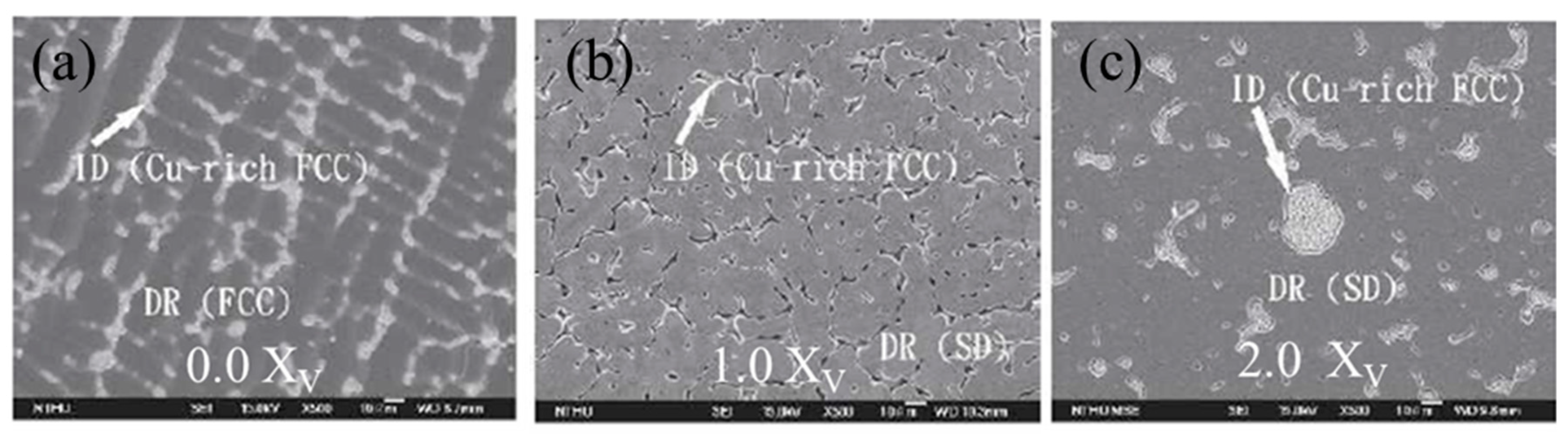
Figure 27.
Summary of mechanical, tribological and metallurgical properties of Al0.5CoCrCuFeNi-X alloy system. Improved wear resistance of the alloys with increasing proportions of (a) Vanadium (b) Boron and (c) Aluminum; (d) relative comparison and summary of wear resistance of Al0.5CoCrCuFeNi-X alloys where X is V, B and AlyCoCrCuFeNi where y is 0.3, 1.0 and 1.5 [38,89,90].

Figure 28.
(a–d) Wear track morphology and wear particle morphology showing clear (e,f) delamination wear and (g,h) partial oxidation wear on the AlxCo1.5CrFeNi1.5Tiy alloys [91] (reprinted with permission from Elsevier).
Figure 28.
(a–d) Wear track morphology and wear particle morphology showing clear (e,f) delamination wear and (g,h) partial oxidation wear on the AlxCo1.5CrFeNi1.5Tiy alloys [91] (reprinted with permission from Elsevier).

Figure 29.
Scanning electron microscope images of Al0.25CoCrFeNiTi0.75 alloy in as-cast condition. (a) Low magnification scanning electron image of the alloy; (b) high magnification image showing the three distinct contrasts - lighter contrast phase is chi (χ) phase, the darker contrast phase as the FCC based ordered phase, and the greyish phase as disordered FCC; EDS elemental maps showing distribution of (c) Co (d) Ti (e) Ni (f) Al (g) Fe and (h) Cr [92] (reprinted with permission from Elsevier).

Figure 30.
Wear behavior of Al0.2Co1.5CrFeNi1.5Ti1.0 alloy. The alloy showed increased wear volume loss with increased load, corresponding well with archard’s law. High magnification SEM images, and EDS maps shows oxides on the surface, indicating oxidative wear operating on the sample surface [92] (reprinted with permission from Elsevier).

Figure 31.
Interferometry images of dry wear track for (a) CoCrFeMnNi and (b) Al0.1CoCrFeNi. Scanning Electron Microscope images of wear track on (c) CoCrFeMnNi and (d) Al0.1CoCrFeNi; Higher magnification images of wear tracks for (e) CoCrFeMnNi showing coarse microabrasion/microcutting and (f) Al0.1CoCrFeNi showing finer microabrasion, deformation and delamination of oxide layer; The corresponding interferometry images of wear tracks generated during marine wear for (g) CoCrFeMnNi and (h) Al0.1CoCrFeNi. Scanning Electron Microscope images of wear track due to corrosive wear on (i) CoCrFeMnNi and (j) Al0.1CoCrFeNi; Higher magnification images of wear tracks for (k) CoCrFeMnNi showing fine microabrasion/microcutting and shallow deformation and (l) Al0.1CoCrFeNi showing corrosive wear in terms of break-down of surface passive layers [31] (reprinted with permission from Elsevier).

Figure 32.
Hardness-wear resistance relationship classified with respect to their magnitude of wear resistance (a) less than 2.5 m/mm3; (b) between 500 and 6000 m/mm3. The wear performance of the alloys do not show a particular dependency on the crystal structure.
Figure 32.
Hardness-wear resistance relationship classified with respect to their magnitude of wear resistance (a) less than 2.5 m/mm3; (b) between 500 and 6000 m/mm3. The wear performance of the alloys do not show a particular dependency on the crystal structure.

Figure 33.
(a) SEM micrograph of AlCrSiTiV CCA coating on Ti-6Al-4V substrate and (b) specific wear rate of two materials after dry sliding wear test under various frequencies [97] (reprinted with permission from Elsevier).
Figure 33.
(a) SEM micrograph of AlCrSiTiV CCA coating on Ti-6Al-4V substrate and (b) specific wear rate of two materials after dry sliding wear test under various frequencies [97] (reprinted with permission from Elsevier).

Figure 34.
Future opportunities and outlook for complex concentrated alloys.


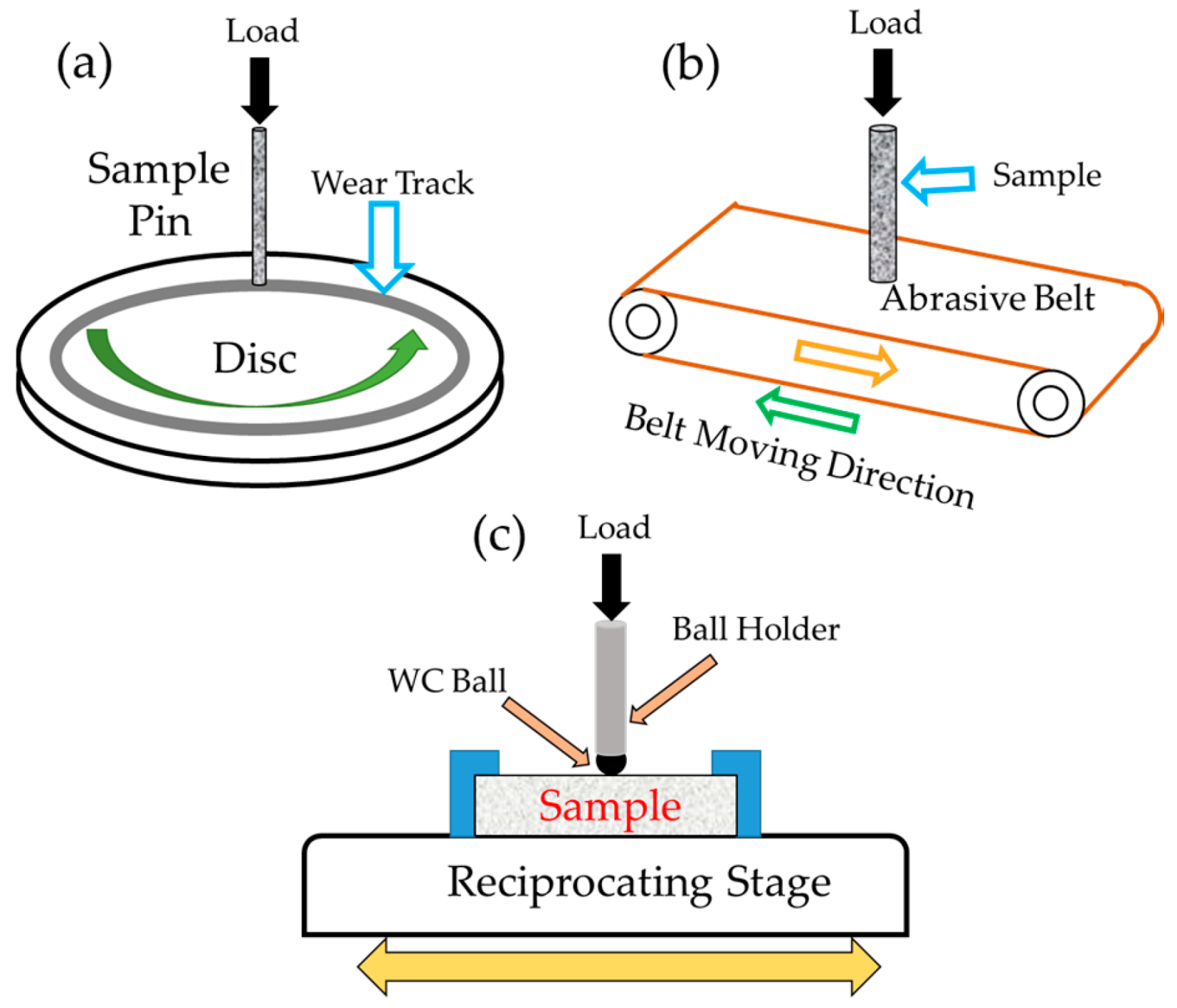
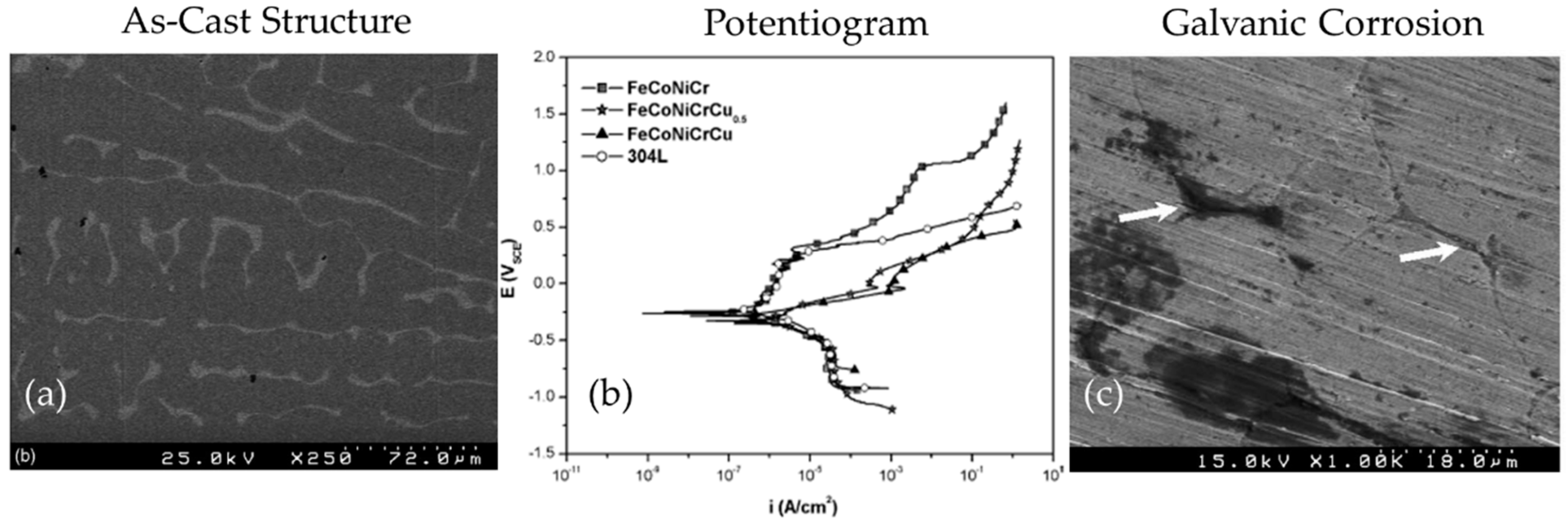
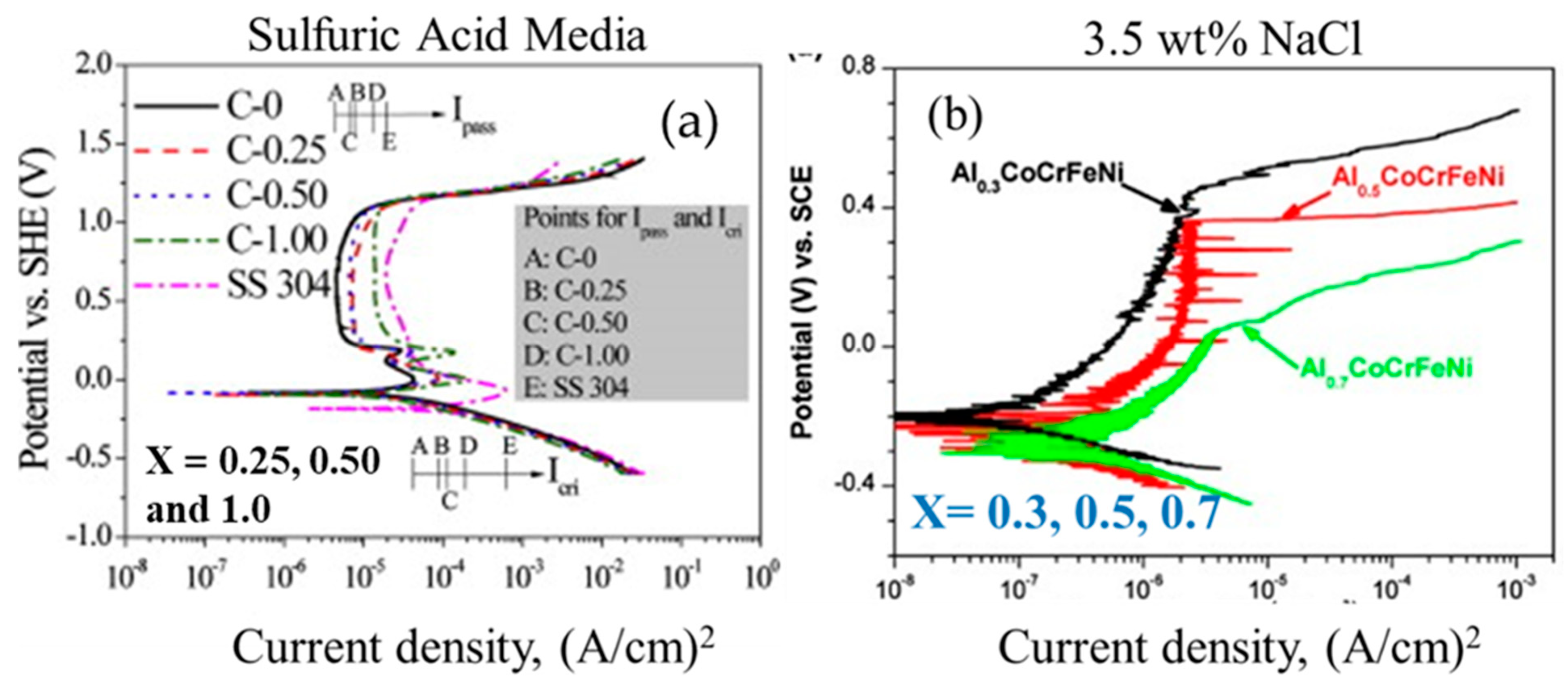
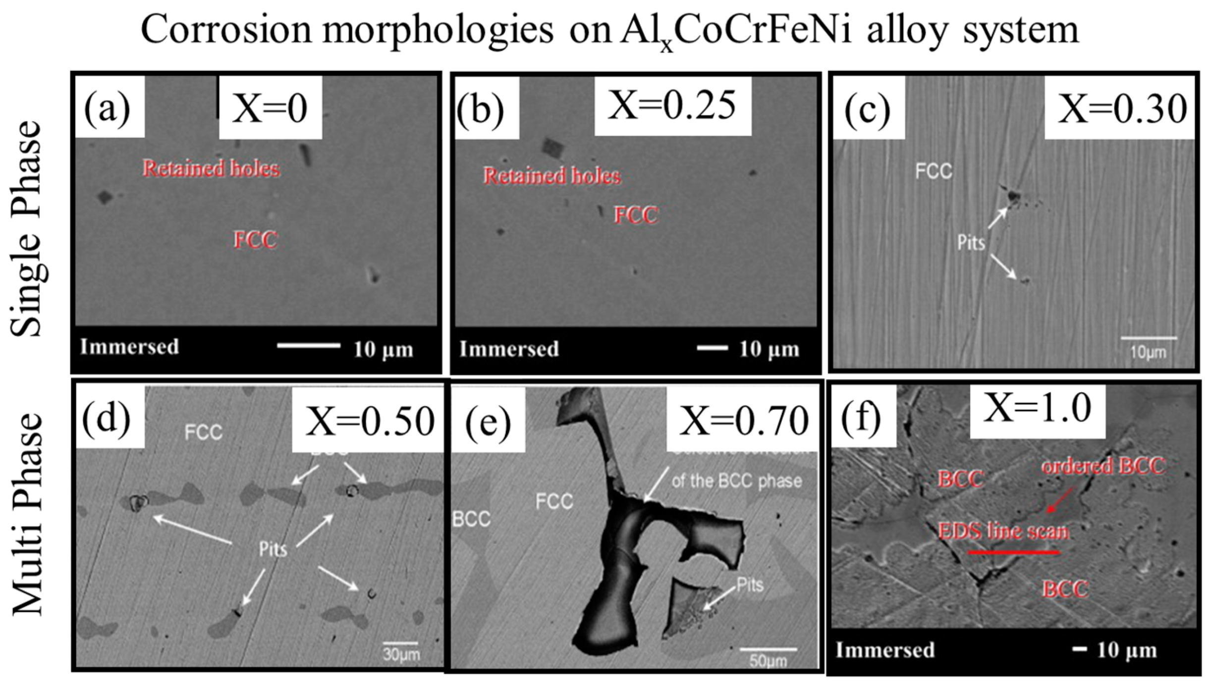
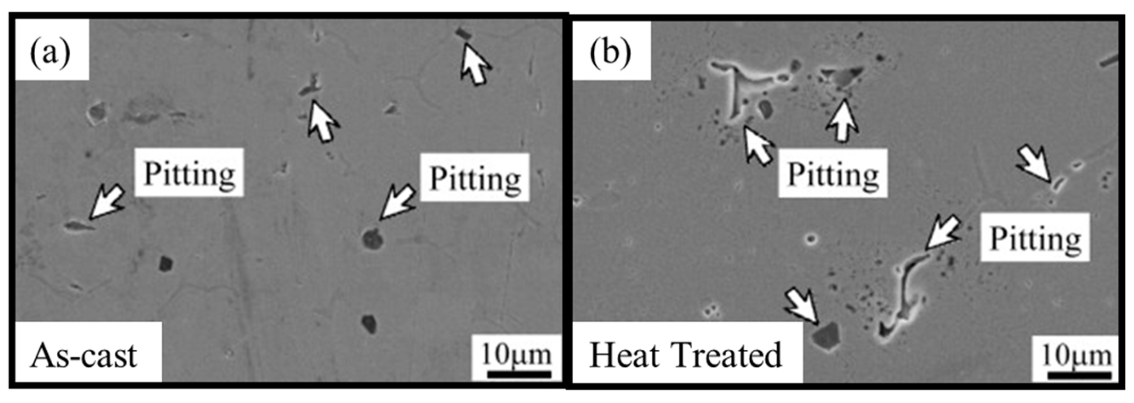
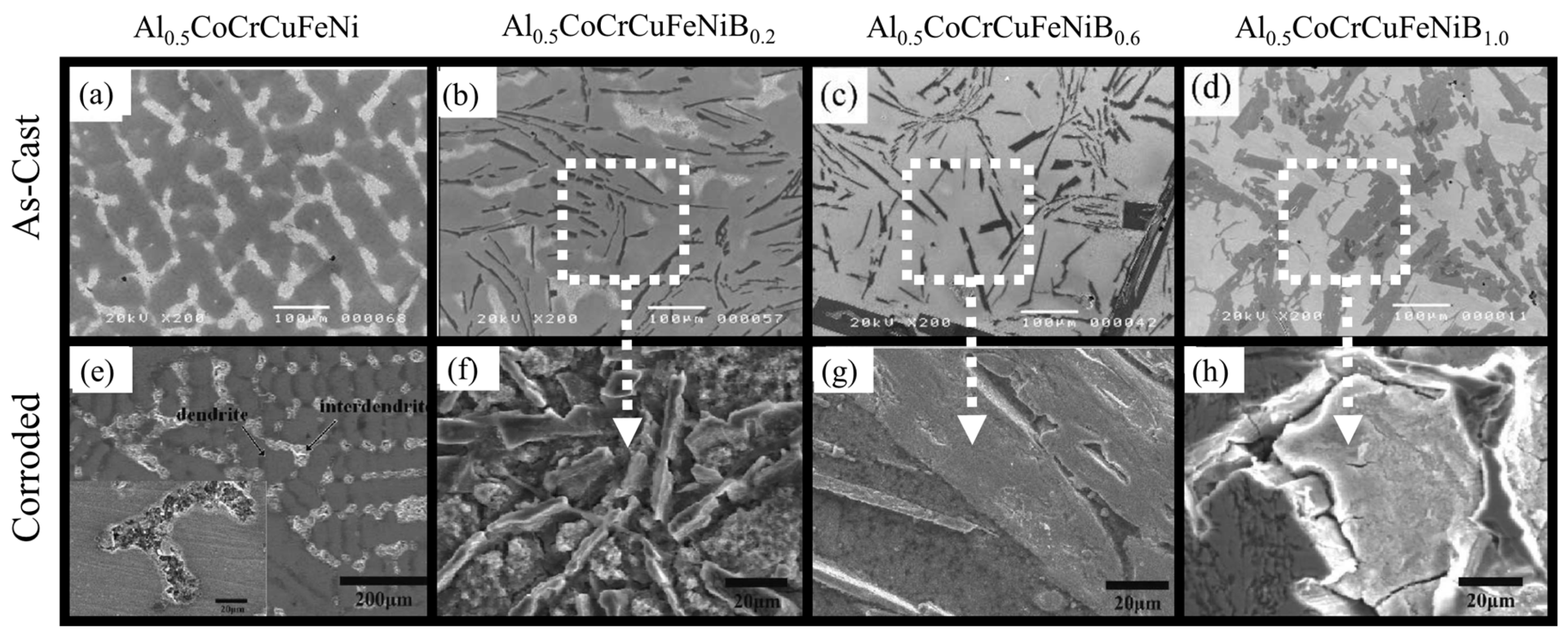
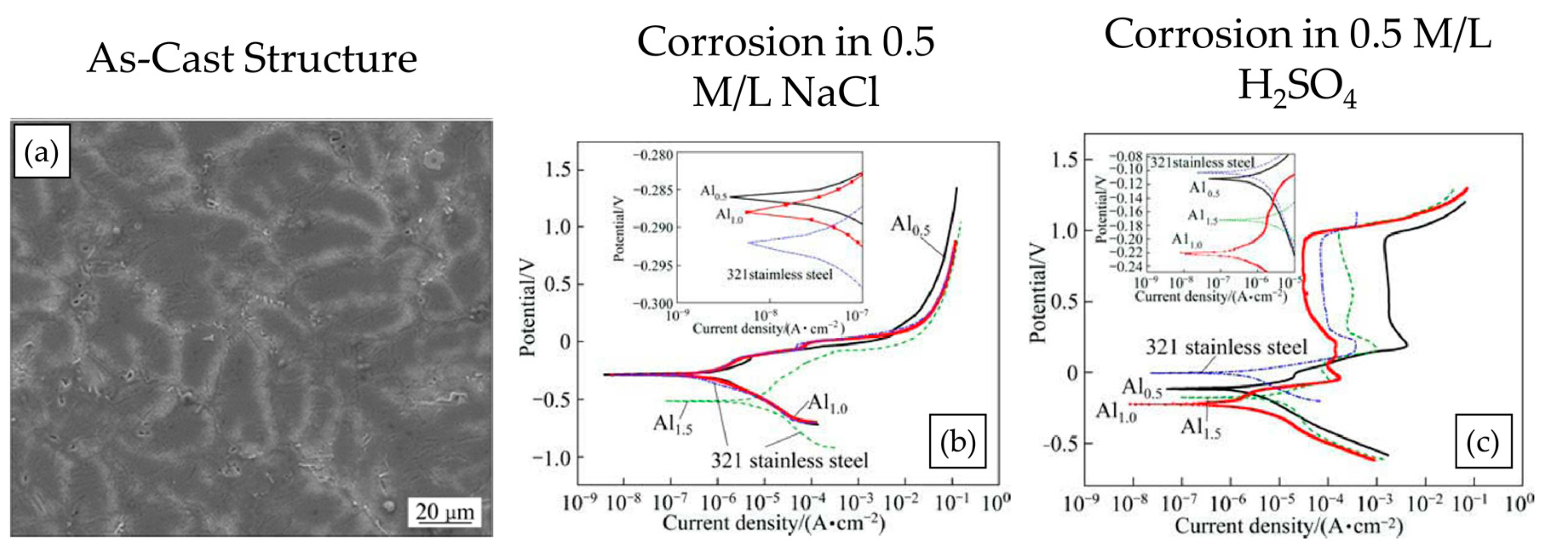
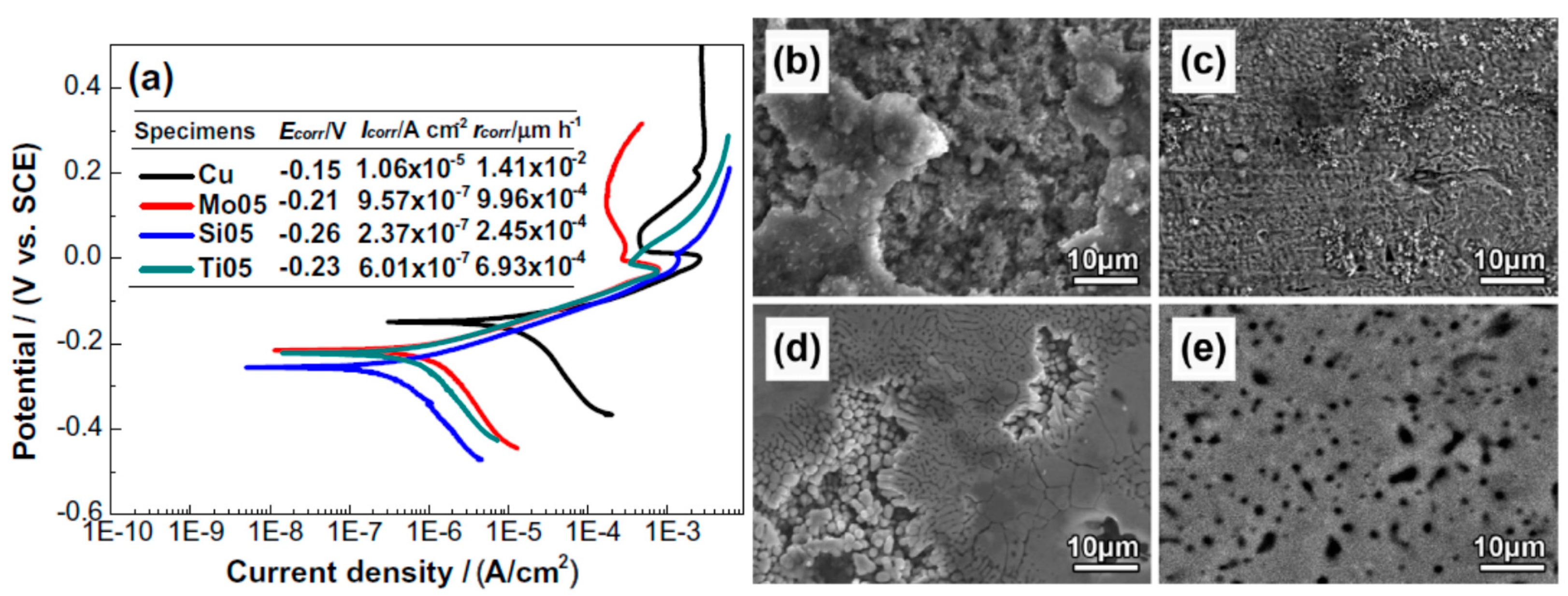
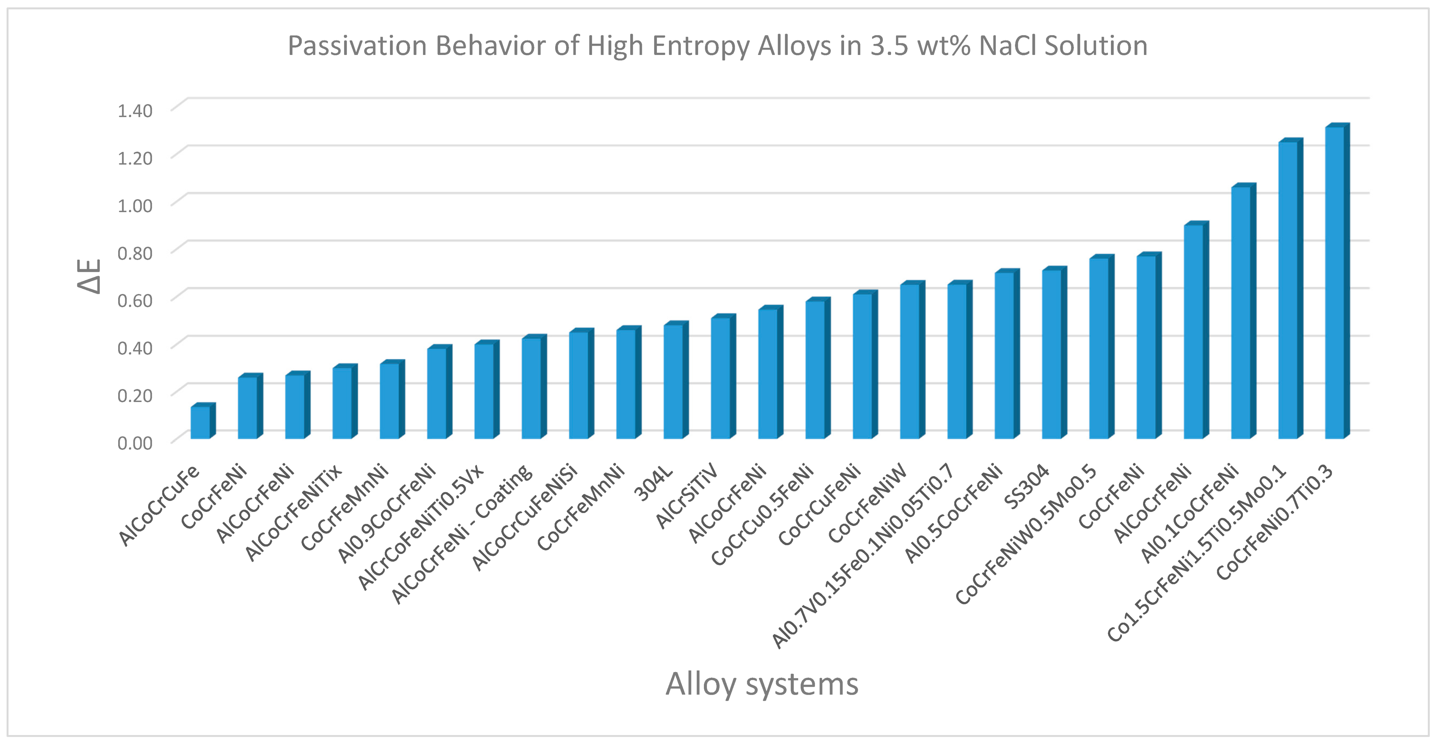
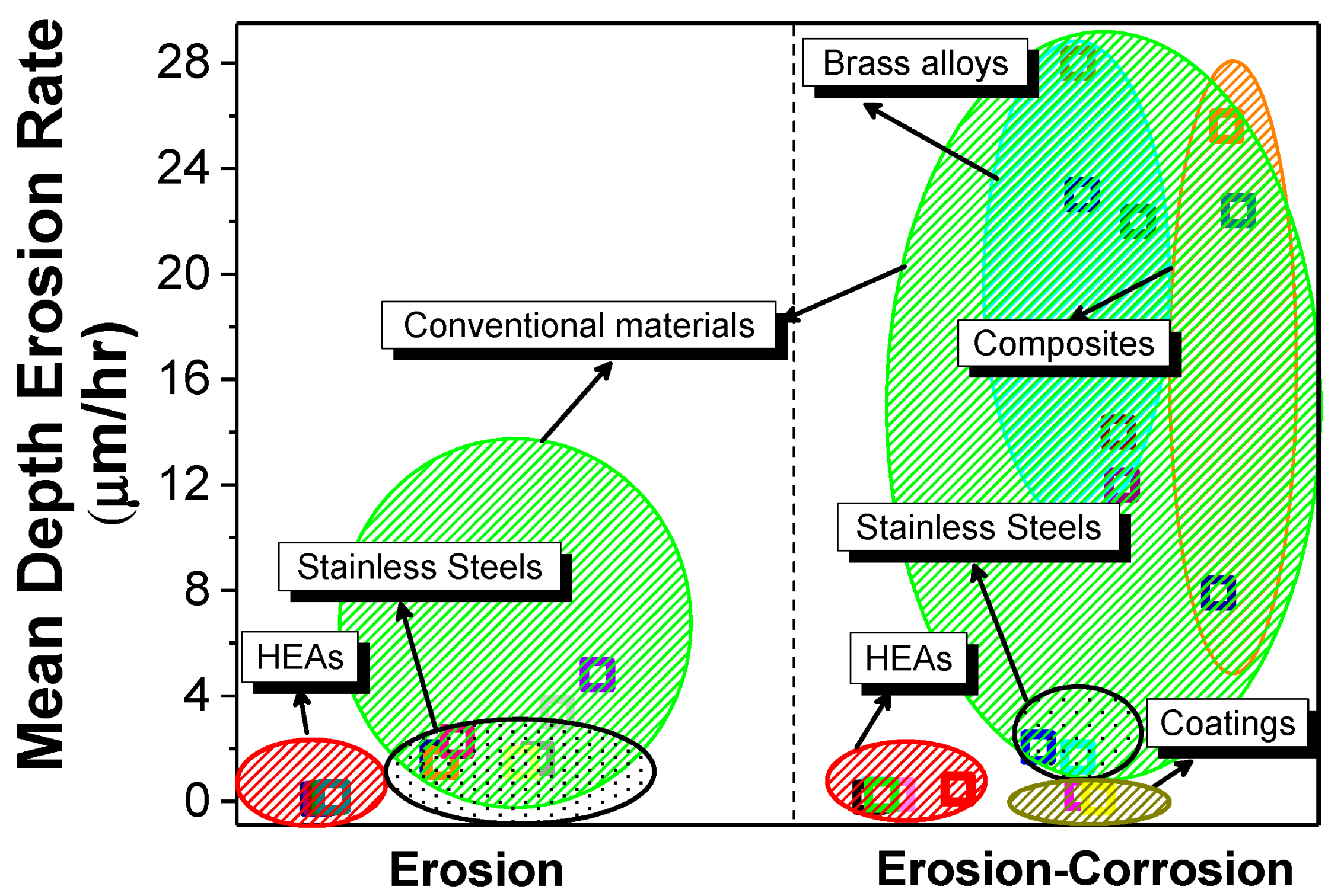
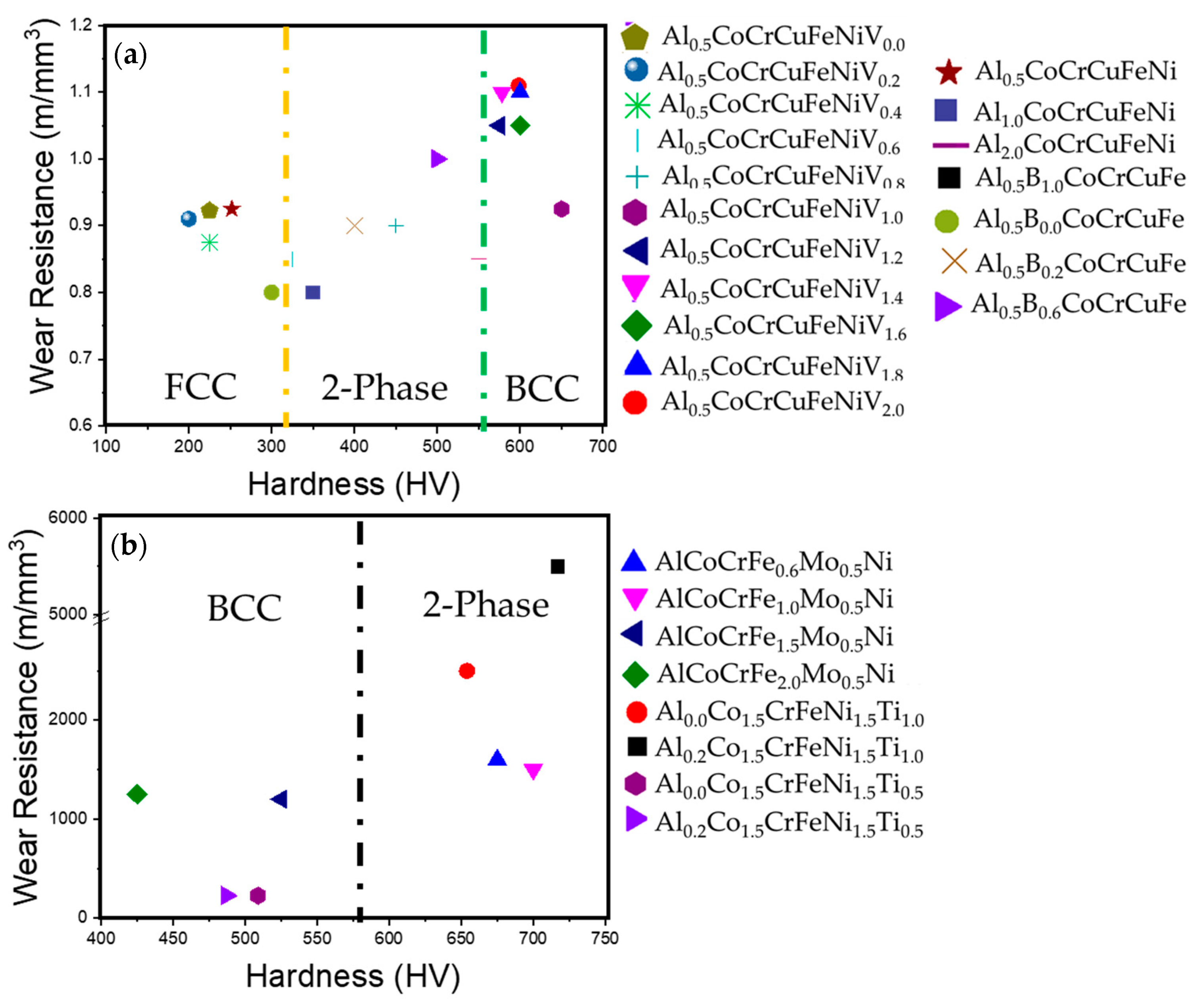
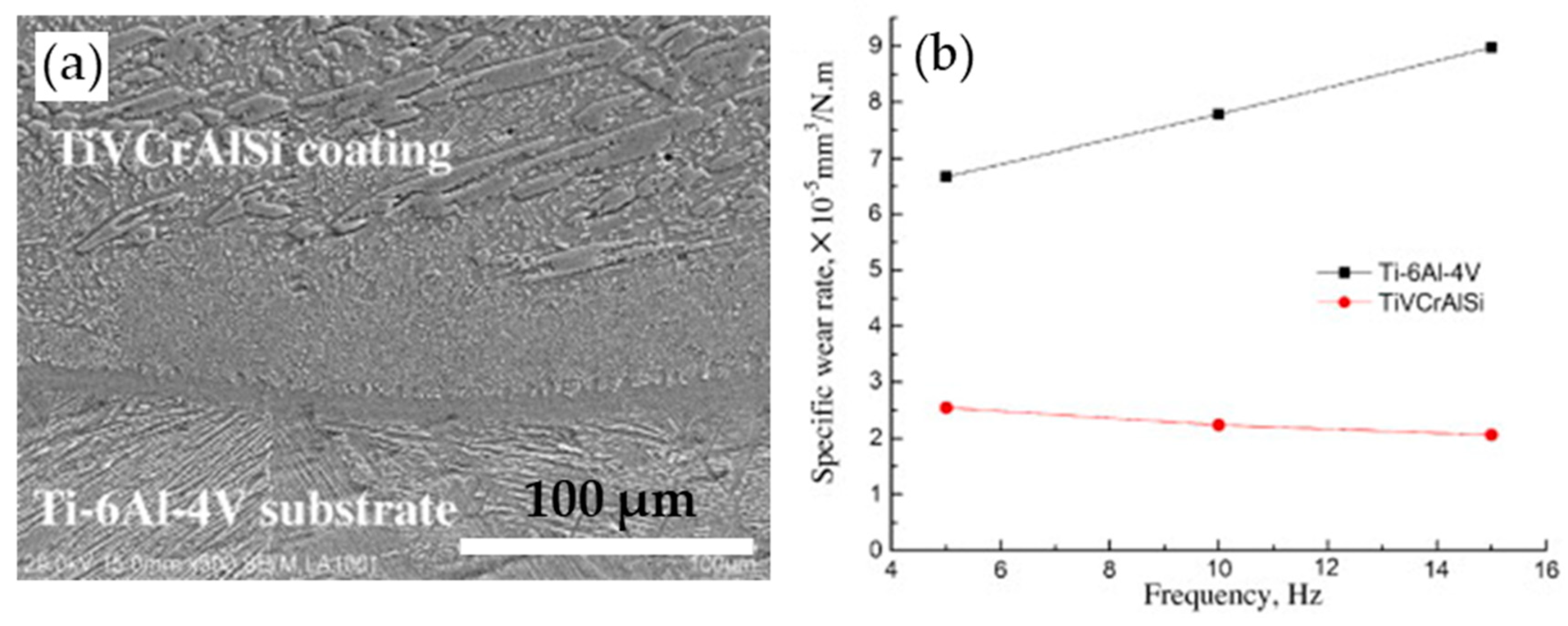
Table 1.
Process parameters that affect the erosion process [24].
Table 1.
Process parameters that affect the erosion process [24].
| Flow Related Parameters | Erodent Related Parameters | Materials Related Parameters |
|---|---|---|
|
|
|
Table 2.
Summary of potentiodynamic/anodic polarization tests of various complex concentrated (high entropy) alloys in aqueous, acidic, and sulfate solutions.
Table 2.
Summary of potentiodynamic/anodic polarization tests of various complex concentrated (high entropy) alloys in aqueous, acidic, and sulfate solutions.
| Complex Concentrated Alloy | Microstructure | Corrosion Environment | Test Procedure/Analysis | Major Finding |
|---|---|---|---|---|
| AlCoCrCu0.5FeNiSi [18] | Two Phase: Dendritic phase: mixture of amorphous and BCC; Inter-dendritic phases: amorphous and nano-scale precipitates | 3.5 wt% NaCl, H2SO4 at 30–70 °C | Anodic polarization | CCA showed overall better corrosion resistance than SS304, but had poor pitting resistance; Corrosion resistance was lower than SS304 at higher temperatures |
| Al0.1CoCrFeNi [31] | Single phase FCC | 3.5 wt% NaCl | Potentiodynamic Polarization | Very high corrosion resistance, passive region as wide as 1 V; Grain boundary corrosion, very low corrosion current density |
| Al0.3CrFe1.5MnNi0.5Tix [61] | BCC with increasing intermetallic with increasing Ti | 3.5 wt% NaCl | Potentiodynamic Polarization | Adding Ti lowered corrosion resistance |
| Al0.3CrFe1.5MnNi0.5Six [61] | BCC with increasing intermetallic with increasing Si | 3.5 wt% NaCl | Potentiodynamic Polarization | Adding Si lowered corrosion resistance |
| Al0.5CoCrCuFeNiBx [39] | FCC + BCC crystal structure | 1 N H2SO4 | Anodic polarization | CCA was nobler than SS304 in terms of corrosion current density, and corrosion potentials; not susceptible to localized corrosion in sulfate solutions |
| Al0.5CoCrFeNi [35] | FCC solid solution matrix with secondary phases rich in Al–Ni | 3.5 wt% NaCl | Potentiodynamic Polarization | Secondary phases rich in Al–Ni were more susceptible to corrosion |
| Al2CrFeNiCoCuTix [51] | x = 0.0 FCC + BCC1 | 0.5 M HNO3 | Potentiodynamic Polarization | Increasing Ti content increased corrosion resistance in terms of corrosion current density |
| x = 0.5 FCC + BCC2 | ||||
| x = 1.0 BCC1 + BCC2 | ||||
| x = 1.5 BCC1 + BCC2 | ||||
| x = 2.0 FCC + BCC2 | ||||
| AlCoCrCuFeNi [37] | FCC + BCC two phase mixture | 1 mol/L NaCl | Potentiodynamic Polarization | Good corrosion resistance despite two phase structure |
| AlCoCrFeNi [62] | BCC | 3.5 wt% NaCl | Potentiodynamic Polarization | Corrosion resistance after processing was three orders of magnitude better than steel and one order of magnitude better than unprocessed HEA |
| AlCoCrFeNiTi [36] | Complex Microstructure: Al, Co, Ni and Ti rich dendritic phase. Fe and Cr rich inter-dendritic phase. Ti and Ni rich third phase. Ordered phase—A2, B2, D03 and A12 | 3.5 wt% NaCl | Polarization | Ti addition improved corrosion resistance of the alloy; Through the re-melting process, the distribution of elements in the alloy improved, improving the corrosion resistance |
| AlCrCuFeMnNi [63] | Complex Microstructure: BCC dendritic phase, interdendritic area with two phases—a eutectic type and FCC solid solution phase | 3.5 wt% NaCl | Potentiodynamic Polarization | CCA was easier to passivate; higher corrosion resistance than SS304L; Galvanic coupling reduced by dissolving Cu during re-melting |
| AlxCoCrCu0.5FeNi [41] | x = 0.5 is FCC | 0.5 mol/L H2SO4 + 0.5 mol/L NaCl solution | Potentiodynamic Polarization | Single-phase alloys had better corrosion resistance that phase mixtures; BCC alloy was comparable with 321 stainless steel |
| x = 1.0 is BCC | ||||
| x = 1.5 FCC + BCC | ||||
| AlCoCrCuFe [49] | FCC and BCC phase mixture | 1 mol/L NaCl and 0.5 mol/L H2SO4 | Potentiodynamic Polarization | Segregation of Cu was seen in the microstructure; CCA performed better in NaCl solution than in acidic solution |
| AlxCoCrFeNi (x = 0, 0.25, 0.50, 1.00) [33] | x = 0 | 0.5 mol/L H2SO4 | Potentiodynamic Polarization | Corrosion current density decreased with Al content at 23 °C; Overall superior corrosion resistance compared to steels |
| x = 0.25 | ||||
| x = 0.50 | ||||
| x = 1.00 | ||||
| AlxCoCrFeNi [34] | x = 0.3 | 3.5 wt% NaCl | Potentiodynamic Polarization | Increasing Al content decreased corrosion resistance by formation of intermetallic phases |
| x = 0.5 | ||||
| x = 0.7 | ||||
| AlxCrFe1.5MnNi0.5 [66] | x = 0.0 FCC | 1 mol/L NaCl + 0.5 mol/L H2SO4 | Potentiodynamic Polarization | Alloys showed extended passive region, greater than 1 V; Increasing Al lowered corrosion resistance in terms of pitting behavior |
| x = 0.3 BCC + FCC | ||||
| x = 0.5 BCC | ||||
| BxCoCrFeNi [67] | x = 0.5 FCC | 3.5 wt% NaCl | Potentiodynamic Polarization | Corrosion resistance improved with increasing B content up to 1%., beyond which corrosion resistance decreased; The CCAs showed superior corrosion resistance than SS304 |
| x = 0.75 FCC | ||||
| x = 1.0 FCC | ||||
| x = 1.25 FCC + M2B | ||||
| Co1.5CrFeNi1.5Ti0.5Mo0.1 [43] | FCC solid-solution structure | 0.001 to 1 M NaCl and sulfate doped 1 M NaCl | Potentiodynamic Polarization | Sulfate ions increased the pitting potential and critical pitting potential of the alloys |
| Co1.5CrFeNi1.5Ti0.5Mox [42] | FCC solid-solution | 0.5 M H2SO4 1 M NaCl and NaOH | Potentiodynamic Polarization | Mo addition lowered the overall corrosion resistance |
| CoCrCu0.5FeNi [68] | Dendritic Structure: Copper lean dendritic phase, copper rich interdendritic phase, aged at different temperatures | 3.5 wt% NaCl | Potentiodynamic Polarization | Corrosion current density lowered while corrosion potential decreased with aging temperature; Corrosion properties worsened when heat treated at 1100–1350 °C. Pitting increased with aging temperature |
| CoCrCuFeNiNb [55] | FCC and Laves phases | 6 M HCl | Potentiodynamic Polarization | Alloying with Nb lowered corrosion current density |
| CoCrFeMnNi [31] | Simple single phase FCC | 3.5 wt% NaCl | Potentiodynamic Polarization | ~500 mV wide passivation region; Corrosion rate as low as one micron per year |
| CoCrCuxFeNi [29] | FCC and Cu rich FCC | 3.5 wt% NaCl | Potentiodynamic Polarization | Addition of Cu deteriorated the corrosion resistance |
| Immersion Test | Galvanic corrosion between inter-dendritic region and dendrite resulting in localized corrosion | |||
| CoCuFeNiSnx [69] | Single phase FCC solid solution when Sn < 0.09, small BCC phase beyond that | 3.5 wt% NaCl and 5% NaOH | Potentiodynamic Polarization | CCAs showed wide passivation range in NaOH and relatively smaller region in NaCl; Better resistance than SS304; FeCoNiCuSn0.04 showed improved corrosion resistance |
| CoCuFeNiSnx [69] x = 0–0.09 | FCC when x < 0.09, small BCC for x > 0.09 | 3.5 wt% NaCl and 5% NaOH | Potentiodynamic Polarization | Better corrosion resistance than SS304 alloy when tested in NaCl, while lower corrosion resistance when tested in NaOH |
| Cr0.5NbTiZr0.5, Cr0.5NbTiVZr0.5 Cr0.5MoNbTiZr0.5 [70] | Dendritic Structure: BCC Disordered Solid Solution phase and Cr2Zr phase | 3.5 wt% NaCl and 0.5 M H2SO4 | Potentiodynamic Polarization | Superior corrosion resistance, with passive region more than 1400 mV; Mo and V addition decreased corrosion resistance but improved pitting resistance in NaCl and H2SO4 |
| CoCrCuxFeNi [29] | FCC crystal structure, Cu rich interdendritic phase | 3.5 wt% NaCl | Potentiodynamic Polarization | Increasing Cu content caused segregation into inter-dendritic phases, and consequent deterioration of corrosion resistance; General corrosion trend was seen as FeCoNiCrCu > FeCoNiCrCu0.5 > FeCoNiCr |
| CuCr2Fe2Ni2Mn2 Cu2CrFe2NiMn2 [44] | FCC | 1 M H2SO4 | Potentiodynamic Polarization | Cr2 alloy showed better corrosion resistance while Cu2 alloy promoted segregation and had lower corrosion resistance |
| FCC + BCC | ||||
| AlCoCuFeNi AlCoCuFeNiCr AlCoCuFeNiTi AlCoCrCuFeNiTi [40] | FCC + A2 + B2 | 0.5 mol/L H2SO4 | Potentiodynamic Polarization | Adding Ti decreased the corrosion resistance of the AlCoCuFeNi alloys, whereas adding Cr improved corrosion resistance |
Table 3.
Sumamry of wear behavior of alloys reported in literature.
| System | Alloy | Hardness (HV) | Wear Resistance |
|---|---|---|---|
| Al0.5CoCrCuFeNiVx [90] | Al0.5CoCrCuFeNiV0.2 | 200 | 0.910 |
| Al0.5CoCrCuFeNiV0.4 | 225 | 0.875 | |
| Al0.5CoCrCuFeNiV0.4 | 325 | 0.850 | |
| Al0.5CoCrCuFeNiV0.8 | 450 | 0.900 | |
| Al0.5CoCrCuFeNiV1.0 | 650 | 0.925 | |
| Al0.5CoCrCuFeNiV1.2 | 575 | 1.050 | |
| Al0.5CoCrCuFeNiV1.4 | 578 | 1.100 | |
| Al0.5CoCrCuFeNiV1.6 | 600 | 1.050 | |
| Al0.5CoCrCuFeNiV1.8 | 600 | 1.100 | |
| Al0.5CoCrCuFeNiV2.0 | 598 | 1.110 | |
| AlxCo1.5CrFeNi1.5Tiy [91] | Al0Co1.5CrFeNi1.5Ti0.5 | 501 | 250 |
| Al0.2Co1.5CrFeNi1.5Ti0.5 | 480 | 255 | |
| Al0Co1.5CrFeNi1.5Ti | 650 | 2000 | |
| Al0.2Co1.5CrFeNi1.5Ti | 700 | 5500 | |
| AlxCoCrCuFeNi [89] | Al0.5CoCrCuFeNi | 252 | 0.925 |
| Al1.5CoCrCuFeNi | 350 | 0.825 | |
| Al2.0CoCrCuFeNi | 550 | 0.850 | |
| Al0.5BxCoCrCuFe [38] | Al0.5B0CoCrCuFe | 300 | 0.8 |
| Al0.5B0.2CoCrCuFe | 400 | 0.9 | |
| Al0.5B0.6CoCrCuFe | 500 | 1.0 | |
| Al0.5B1.0CoCrCuFe | 725 | 1.6 | |
| AlCoCrFexMo0.5Ni [100] | AlCoCrFe0.6Mo0.5Ni | 675 | 1600 |
| AlCoCrFe1.0Mo0.5Ni | 700 | 1500 | |
| AlCoCrFe1.5Mo0.5Ni | 525 | 1200 | |
| AlCoCrFe2.0Mo0.5Ni | 425 | 1250 |
© 2018 by the authors. Licensee MDPI, Basel, Switzerland. This article is an open access article distributed under the terms and conditions of the Creative Commons Attribution (CC BY) license (http://creativecommons.org/licenses/by/4.0/).
Share and Cite
MDPI and ACS Style
Ayyagari, A.; Hasannaeimi, V.; Grewal, H.S.; Arora, H.; Mukherjee, S. Corrosion, Erosion and Wear Behavior of Complex Concentrated Alloys: A Review. Metals 2018, 8, 603. https://doi.org/10.3390/met8080603
AMA Style
Ayyagari A, Hasannaeimi V, Grewal HS, Arora H, Mukherjee S. Corrosion, Erosion and Wear Behavior of Complex Concentrated Alloys: A Review. Metals. 2018; 8(8):603. https://doi.org/10.3390/met8080603
Chicago/Turabian StyleAyyagari, Aditya, Vahid Hasannaeimi, Harpreet Singh Grewal, Harpreet Arora, and Sundeep Mukherjee. 2018. "Corrosion, Erosion and Wear Behavior of Complex Concentrated Alloys: A Review" Metals 8, no. 8: 603. https://doi.org/10.3390/met8080603
Note that from the first issue of 2016, this journal uses article numbers instead of page numbers. See further details here.