Removal Mechanism of Microscale Non-Metallic Inclusions in a Tundish with Multi-Hole-Double-Baffles


The State Key Laboratory of Refractories and Metallurgy, Wuhan University of Science and Technology, Wuhan 430081, Hubei, China
*
Author to whom correspondence should be addressed.
Metals 2018, 8(8), 611; https://doi.org/10.3390/met8080611
Submission received: 1 July 2018
/
Revised: 2 August 2018
/
Accepted: 3 August 2018
/
Published: 6 August 2018
(This article belongs to the Special Issue 5th UK-China Steel Research Forum)
Abstract
:To effectively remove microscale inclusions in the tundish, the Multi-Hole-Double-Baffles (MHDB), a novel flow control device in the tundish for continuous casting, was developed. The hole array mode of the MHDB will directly affect the trajectories of the inclusions. The effect and removal mechanism of the inclusions with sizes of 1 µm to 50 μm in the tundish with MHDB were studied by numerical simulation. The hole array mode of MHDB could affect the inclusions’ trajectories and distribution, and the mechanism underlying the effect of the MHDB was investigated using the discrete phase model (DPM). A 1:2.5 physical model was built to verify the accuracy of numerical simulation. The results showed that micro-inclusions were primarily driven by the drag force exerted by the molten steel flow, micro-inclusion trajectories followed the molten steel streamlines almost exactly, but buoyancy still played a role in the removal of the micro-inclusions near the molten steel surface; the hole array mode affected the trajectories of the micro-inclusions and controlled and decelerated the flow of molten steel, increasing the residence time of the molten steel flow a the value that is 15 times larger than the theoretical value; and “upper-in-lower-out” type MHDB showed the most efficient removal of micro-inclusions, with the removal rate being increased by 13–49% compared to the removal rates for the other type MHDB. The results of numerical simulation were well verified by physical simulation.
1. Introduction
Owing to the increasingly stringent quality requirements, many studies have investigated the equipment, process, and theoretical principles of continuous casting, particularly for the tundish, which is the final metallurgical element reactor [1,2,3,4,5,6]. To improve the removal of inclusions by the tundish, many flow control devices, such as the turbulence inhibitor, weir-dam, baffle with holes, and filter and gas-curtain device, have been developed to optimize the flow field, increase the residence time, and promote inclusions’ removal [7,8,9,10,11,12,13,14,15,16,17,18].
Because steel grades require an increasingly high degree of purity, particularly for micro-inclusions with sizes of 1 µm to 50 μm, the tundish must be able to remove the micro-inclusions in the steel [19,20,21,22,23]. Unfortunately, the currently used tundishes and in particular the tundish used for high casting speed caster, cannot remove the micro-inclusions effectively [24,25,26,27]. For a more effective micro-inclusions’ removal, the novel Multi-Hole-Double-Baffles (MHDB) device was developed, and the inclusion removal mechanism should be studied to improve the MHDB.
The steady k-ε model is the most useful mathematical model for the detailed studies of the flow field of the tundish, and many flow control devices have been improved by using this approach [28,29,30]. The discrete phase model (DPM) is a useful tool for simulating the inclusion movement in the studies of the inclusion movement mechanism and has been used successfully to carry out many research studies [31,32,33]. In this work, to meet the need for the research on the properties of the novel MHDB device used to control the flow in the tundish, the steady k-ε model and DPM were combined to complete the numerical simulation, so as to investigate the motion behavior of the inclusions in a tundish with the MHDB and to obtain an improved MHDB device for practical use.
2. Structure of MHDB
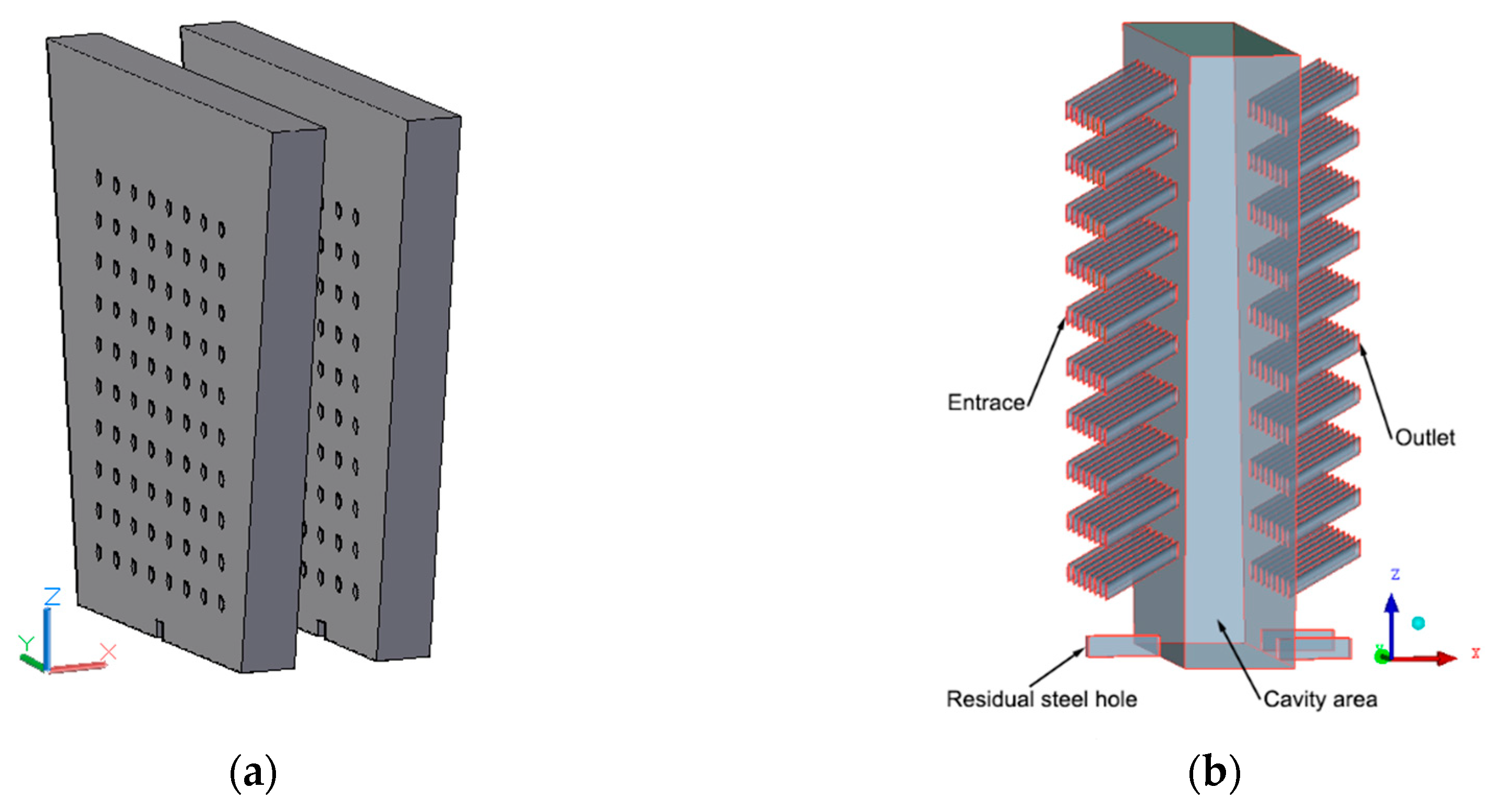
Based on the actual design of an MHDB device in a steel plant (Figure 1a), the 3-dimensional model used in this work was established; the model includes the first and second baffles, the holes in both baffles, the residual steel holes in both baffles and the cavity area between the baffles, as shown in Figure 1b. In continuous casting operation, molten (temperature of 1600 °C) steel from the impact zone of the tundish flows through the holes in the first baffle into the cavity area between the baffles, later first flows through the holes in the second baffle to the outflow zone of the tundish, and subsequently flows through the residual steel holes in the baffles, draining the molten steel in the tundish in the last stage of the casting cycle.
The specific installation location of the MHDB device in the tundish is shown in Figure 2b, and the structure diagram of an original tundish without the MHDB device is shown in Figure 2a. The main flow control device of the original tundish is the upper and lower baffles (UAIB). The installation location of the MHDB device and the UAIB device is basically the same, in which the distance is 500 mm from center line of long nozzle to the MHDB device or the UAIB device.
In the MHDB, guide-holes were set at an angle of 30° upwards, the diameter of the holes was 30 mm, and the MHDB configuration details are summarized in Table 1. Three array modes for the guide-holes in the baffles are investigated: 5 rows of upper holes in the first baffle and 5 rows of lower holes in the second baffle (upper-in-lower-out, UILO mode); 5 rows of lower holes in the first baffle and 5 rows of upper holes in the second baffle (lower-in-upper-out, LIUO mode); 5 half-rows of lower holes and 5 half-rows of upper holes in the first baffle, as well as 5 half-rows of upper holes and 5 half-rows of lower holes in the second baffle (X mode), as shown in Figure 3.
3. Mathematical Model
3.1. Model Assumptions
Based on the physical properties of molten steel and the characteristics of the flow field in the tundish, the assumptions for the model used in this work were as follows:
- The flow in the tundish is turbulent flow, and the molten steel is an incompressible viscous fluid;
- The inclusions do not influence the flow field, but the flow field does influence the movement of the inclusions;
- The inclusions are spherical;
- The molten steel surface is stable, and the slag layer is not considered;
- The movement of the inclusions is simulated using a stochastic motion model.
Therefore, in this work, the flow field in the tundish with the MHDB device is simulated using a steady turbulence isothermality model of an incompressible viscous fluid, and a constant flow rate at the model inlet.
3.2. Governing Equations and Boundary Conditions
The standard k-ε model is established to simulate the flow field in the tundish with MHDB. The control equations are as follows.
The continuity equation:
∂ρ/∂t + ∂ρui/∂xi = 0
The momentum conservation equation (Navier-Stokes equations):
∂(ρui)/∂t + ∂(ρuiuj)/∂xj = −∂P/∂xi + ∂[μeff(∂ui/∂xj + ∂uj/∂xi)]/∂xi
The turbulent kinetic energy equation, k-equation:
∂(ρk)/∂t − ∂(ρkui)/∂xi = ∂[(μt/σk + μ)(∂k/∂xi)] + Pk – ρε
The turbulent dissipation rate equation, ε-equation:
where
where ui (i = 1, 2, 3) are the velocity components in the X, Y, Z directions, respectively; ρ is the fluid density (kg/m3); P is the pressure (Pa); t is the time (s); μeff is the effective viscosity (Pa∙s); μt is the turbulent viscosity (Pa∙s); and μ is the laminar viscosity (Pa∙s); C1 = 1.44, C2 = 1.92, Cμ = 0.09, σk = 1.0, and σε = 1.3.
∂(ρε)/∂t − ∂(ρεui)/∂xi = ∂[(μt/σε)(∂ε/∂xi)]/∂xi + C1(ε/k)Pk − C2ρ(ε2/k)
Pk = μt(∂uj/∂xi)(∂ui/∂xj + ∂uj/∂xi)
μeff = μ + μt = μ + ρCμk2/ε
The trajectories and distributions of the inclusions (1 μm~50 μm) were simulated using the Discrete Phase Model (DPM). In the model, the density of inclusions is 3000 kg/m3, and the diameter distribution of particles is discontinuous and is divided into 11 sizes, including 1, 5, 10, 15, 20, 25, 30, 35, 40, 45, 50 μm. In the integral Lagrangian coordinate system, the trajectory of an inclusion is described by the particle force differential equation.
∂up/∂t = FD(u − up) + gi(ρp − ρ)/ρp + Fi
Re = ρdp|up − u|/μ
CD = α1 + α2/Re + α3/Re2
where u is the velocity of the fluid phase; up is the velocity of the particle phase; μ is the kinetic viscosity of the fluid; ρ is the density of the fluid phase; ρp is the density of the particle phase; dp is the particle diameter; Re is the Reynolds number of the particle; FD is the drag force; Fi is the other force (i = x, y, z); CD is the drag force coefficient; and α1, α2, α3 are the constants for a spherical particle in a certain range of Reynolds numbers [34].
The model boundaries are set as follows.
- The model inlet of tundish was set as the inlet with the velocity derived from the casting speed. Similarly, the inlet of MHDB was set as the velocity inlet, and this velocity is determined by measuring the average velocity of each guide-hole in the simulation of the tundish. The inclusions were injected into the inlet at the same velocity, and the diameter distribution of inclusions is set to “uniform”, which means that the number of inclusion particles for each diameter is the same. Moreover, the inlet velocity of the unused holes is set to zero;
- The liquid surface was set to be a free surface with zero normal velocity and gradient, and the inclusions were trapped at the liquid surface;
- The wall of the tundish was a modeled as a no-slip boundary, and using the Users Defined Function (UDF) in ANSYS Fluent code to define the wall boundary condition, the inclusions could be removed directly from the computing domain when inclusion particles collided with the wall and the speed was less than 0.01 m/s, otherwise it can be reflected from the wall;
- The model outlet was set as the pressure outlet, and for the inclusions, the model outlet was the escape outlet.
Based on the assumptions, governing equations and boundary conditions described above, the model space was partitioned using ICEM software (15.0, Ansys Inc., Canonsburg, PA, USA), and the mathematical model was derived using the FLUENT software (15.0, Ansys Inc., Canonsburg, PA, USA), as shown in Figure 4. Finally, the flow field in the tundish with MHDB was derived using the model. The meshes of the tundish computational domains included non-uniform grids with about 1.4 million cells, yet the non-uniform grids of the MHDB computational domains were more than 8.4 million cells. The numerical model applies the Coupled algorithm with FLUENT software to simulate the three-dimensional flow field and the movement track of particle in the tundish, and the second order upwind scheme is used to the scatter of the equation. The Residual value equation is less than 10−5 as the convergence standard solving the continuity equation, momentum equation and other equations.
4. Results and Discussion
4.1. Flow Field
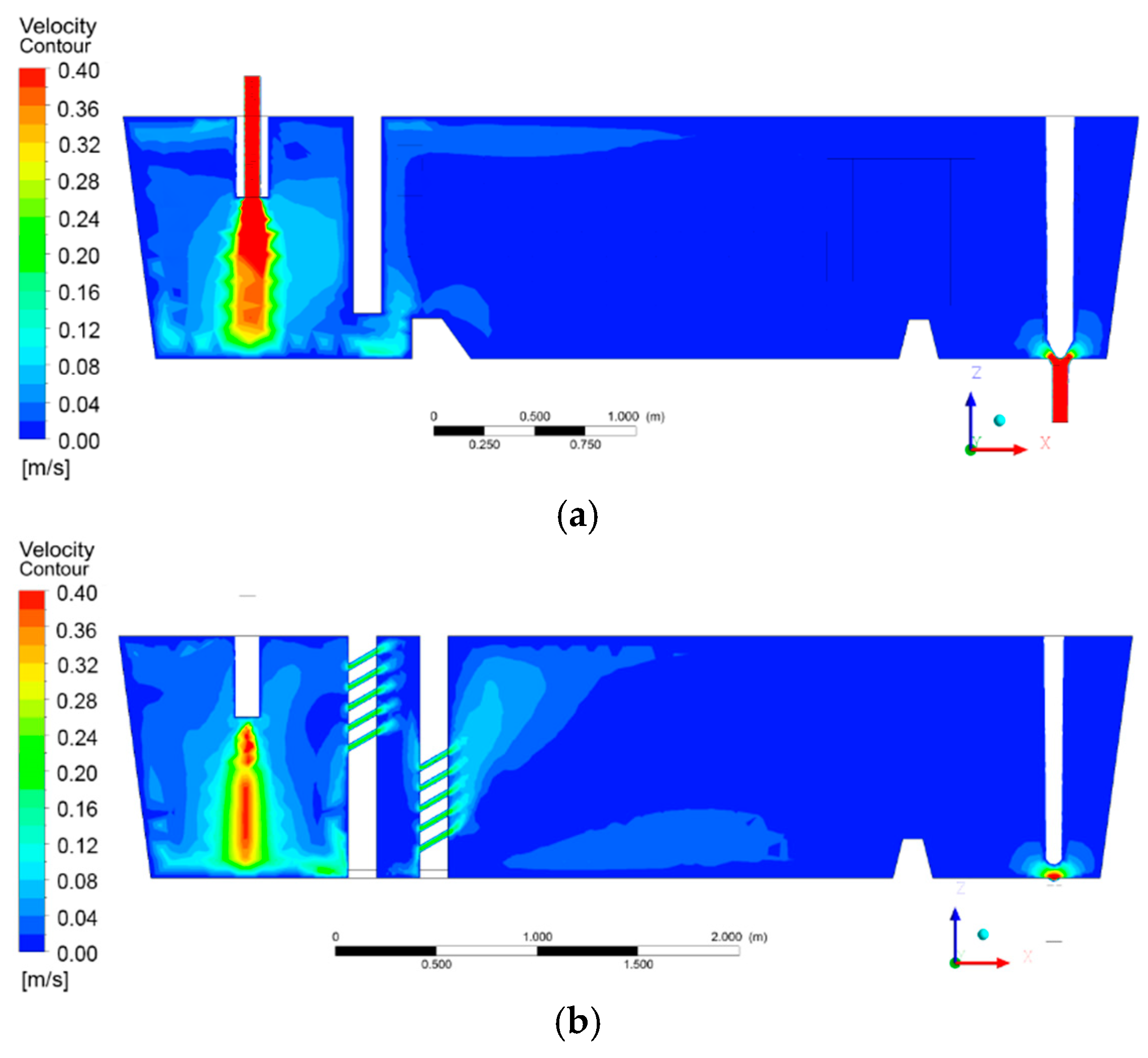
In order to compare the flow field in the tundish with different control flow devices and provide the initial conditions for the simulation of the internal flow field in the MHDB, the original tundish and the tundish with MHDB device were simulated, and the concrete results were shown in Figure 5.
From the Figure 5, it is seen that the velocity of the most part of the flow field in the tundish is lower than 0.4 m/s, in which the velocity of the pouring area is obviously higher than the other areas of the tundish, and the baffles play a very good role in stabilizing the flow field. Through comparison of the high-speed flow areas produced by different control flow devices, it is seen that the high-speed upward stream formed by the UAIB device is only concentrated on the small area close to the surface of upper wall, and the continuity of surface flow is poor after upward stream reaches the slag layer on top surface. In contrast, the MHDB device can not only form obvious upward stream in the internal region of MHDB, but also produce a relatively larger area of upward stream in the downstream area of the tundish, and the continuity of the surface flow is better. Therefore, the MHDB device can provide a good effect on the flow control in the tundish, significantly increase the number and range of high speed upward streams of liquid steel, and promote the surface flow, which is beneficial to the removal of inclusions in the molten steel.
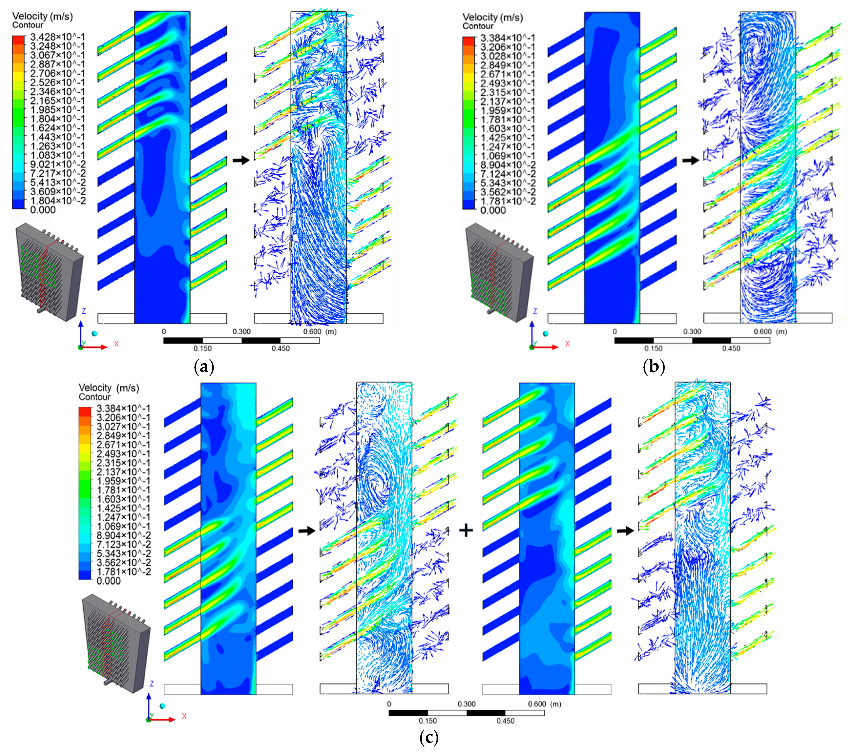
Based on the model described above, the flow fields in the tundish with MHDB in different hole array modes were derived and analyzed (Figure 6).
In Figure 6, the schematic diagram of the MHDB is located at the lower left of each picture, in which green points mark the effective holes for the steel flow through the holes, and red lines mark the section containing the vector and contour graphs. For the MHDB in the UILO mode, after the steel flowed through the guide-hole (at the angle of 30°, inclined up) in the upper rows in the first baffle, the stream first flowed upwards to the molten steel surface and later turned downwards along the secondary baffle and flowed out through the guide-holes in the lower rows, as shown in Figure 6a. An examination of the vector graph in Figure 6a shows that the streams from the holes of the different rows move across each other, producing many vortices in the upper region of the cavity area between the baffles; these vortices promote the coagulation of the micro-inclusions and the trapping of the micro-inclusions at the molten steel surface and in the secondary baffle. An examination of the contour diagram in Figure 6a shows that as the steel flow returned down just along the secondary baffle, the steel stream clearly decelerated, promoting the coagulation of the inclusions with different sizes. It is observed in Figure 6b that in the tundish with the LIUO mode, the steel streams from the different rows of the guide-holes in the first baffle extended parallel to each other and did not move across each other; additionally, a short-cut flow was observed in the cavity area, and the inclusions had more opportunity to become trapped in the secondary baffle. For the tundish with the MHDB in the X mode (Figure 6c), it was found that the flow mode in the cavity area was a mixture of the flow mode of the MHDB in the LIUO mode and the flow mode of the MHDB in the UILO mode, but more vortices were formed by the cross flow of the semi-LIUO mode and the semi-UILO mode in the central region of the cavity area between the baffles. Based on the examination of all of the stream-line diagrams in Figure 7, it was found that the cavity area between the baffles is an effective decelerating device due to its enhancement of the zigzag of the steel flow that increases the residence time of the steel flow in the tundish and forms many vortices, favoring the removal of the inclusions.
4.2. Distribution of Inclusions
4.2.1. Trajectories of the Inclusions
The inclusions in the tundish were driven by two forces, namely, buoyancy and the drag force exerted by the steel flow. An examination of Figure 8 shows that the trajectories of the inclusions were identical to the stream-lines of the flow field in the tundish. Therefore, for the 1–50 μm micro-inclusions, the most significant force on the inclusions is the drag force exerted by the steel flow, and buoyancy has little effect on the micro-inclusion trajectories.
4.2.2. Residence Time of the Inclusions
Figure 9 shows that a time of 1 s was required for the inclusions to move through the guide-holes in the first baffle, and an additional 5 s were necessary for the inclusions to cross the cavity area between the baffles to reach the positions in the vicinity of the holes in the secondary baffle. During this stage, many inclusions were trapped at the liquid surface and in the secondary baffle, and then 50 s were required for the main stream of the inclusions to move into the MHDB. To compare the MHDBs in different modes, the residence time of the inclusions was evaluated using the numerical simulations results, with the obtained results being summarized in Table 2.
In Table 2, Min residence time denotes the results for the inclusions in the short-cut flow through the MHDB, and the obtained Min residence times varied over the range of 2 s to 3 s. Max residence time denotes the results for the inclusions in the center of the vortices in the MHDB, and the obtained Max residence time values were in the range of 470 s to 500 s. It is observed that the differences between the Min and Max residence times of the MHDBs in different modes are slight. By contrast, clear differences were observed between the mean residence times of the MHDBs in different modes; for example, the mean residence time of the MHDB in the UILO mode was 37.96 s, which is longer than the mean residence times for the MHDBs in the other two modes, and 15 times longer than the theoretical residence time obtained by the division of the steel flow rate by the cross-section area of the tundish.
4.2.3. Distribution of the Inclusions
Figure 10 shows the distributions of the inclusions in the MHDB. It is clearly observed from Figure 10 that for the UILO mode, the inclusions were distributed largely in the upper part of the cavity area, while for the LIUO mode, the inclusions were mostly located in the medium area in the vicinity of the secondary baffle region of the cavity area, and for the X mode, the inclusions were largely located in the upper corner zone and the medium level region of the cavity area near the secondary baffle. It is clear from Figure 10 that the distribution of the inclusions is more concentrated in the X mode, implying that the X mode promotes micro-inclusions’ coagulation.
Figure 11 shows the inclusions’ distribution in the MHDB. It is observed that the UILO mode was more helpful for trapping the inclusions at the molten steel surface because the inclusion density at the surface for the UILO mode (31 cm−2) is three times larger than that for the LIUO mode (9 cm−2) and 1.5 times larger than that for the X mode (Figure 12). The inclusions located at the surface are mostly the inclusions with the sizes larger than 35 μm (Figure 11). A smaller fraction of the inclusions was located in the bottom region that shows little variation between the different modes of MHDB.
Figure 13 shows the fraction of the inclusions removed by the MHDB. It was found that the values of the fraction of the inclusions removed by MHDB are in the order of UILO mode1 > X mode > LIUO mode. For the UILO mode, the inclusion removal fraction was 48.72%, while for the X mode, it was 47.01%, and for the LIUO mode, it was 42.95%. For the UILO mode, the residence time of the steel flow was long and surface flow was strong such that many inclusions were trapped by the molten steel surface. For the X mode, the surface flow was also strong and many inclusions were concentrated along the secondary baffle, so that many inclusions were trapped at the surface and in the secondary baffle. Additionally, many vortices and cross-flows were observed in the MHDB in the UILO or X modes.
4.3. Inclusion Removing Efficiency
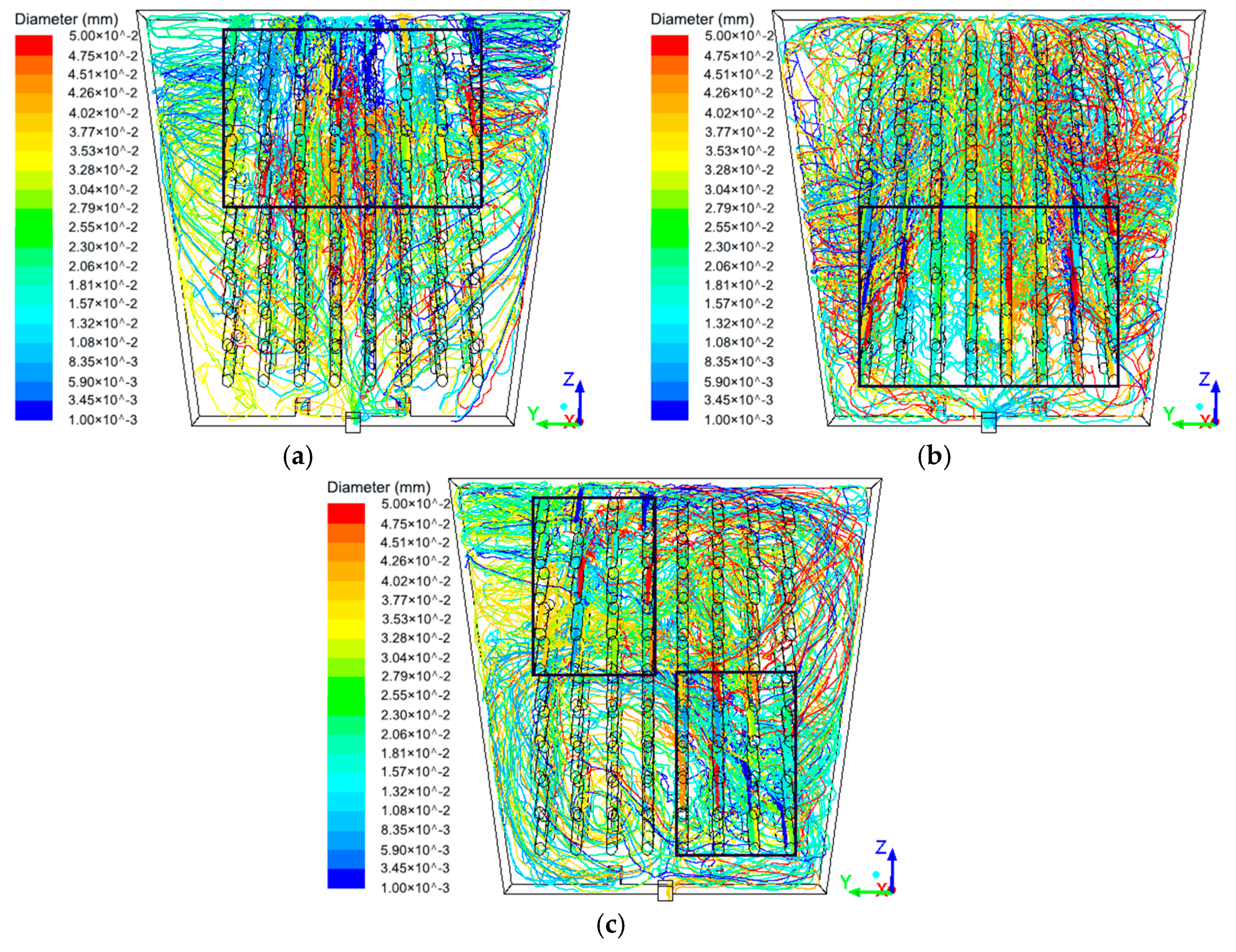
In order to study the concrete application effect of the MHDB device in the tundish and compare with the original tundish with UAIB device, the mico-inclusions with sizes of 1 µm to 50 μm were injected from the inlet of the tundish, and the trajectories of the particles is shown in Figure 14.
As shown in Figure 14, the density of trajectories of the particles gradually decreased in the movement process from the inlet to the outlet of the tundish, indicating that the inclusions could be removed continuously in the flow field of tundish. Most trajectories of the particles were restricted by the baffle and were concentrated in the pouring area, indicating that the baffle was conducive to the removal of inclusion from the molten steel in the pouring area. At the same time, comparing the density of trajectory of the inclusion in the downstream area, it was found that the trajectories’ density of the downstream area and the number of trajectories reaching the outlet in the tundish with MHDB were significantly lower than that in the original tundish. It illustrated that the MHDB device could greatly improve the overall removal effect of inclusions in tundish. Therefore, similar to the conclusions obtained in the previous section, with the combination of Figure 5, the MHDB device effectively limited the movement of inclusions to the downstream area and formed upward streams in the inner of the MHDB and downstream area of the tundish to promote the floatation and removal of inclusions. Compared to Figure 14a,c, it was obvious that the surface flow formed by the MHDB device in the downstream area was more continuous and not easier to fall than that formed by the UAIB device, which was beneficial to the removal of the inclusion in the slag layer.
Figure 15 is a statistical diagram of the overall removal rate of inclusion in the tundish with different control flow devices. From the Figure 15, it was found that the overall removal efficiency of the inclusions in the tundish with MHDB was far better than that of the original tundish, in which the maximum overall removal rate was 96.06%, which is 22.65% more than the removal rate (78.32%) of the original tundish. The effect of MHDB with different structures on removal of inclusion still accorded with the conclusion of the previous section, and the removal rate of the MHDB area for whole tundish was satisfied: UILO (32.37%) > X (30.84%) > LIUO (29.94%). Comparing the removal effect of pouring area, it was seen that the MHDB could increase the removal rate of inclusions in the pouring area more effectively than the UAIB, inhibit the movement of inclusions to the downstream and prevent the nozzle clogging. It was worth noting that the overall removal efficiency of the inclusion in the tundish with MHDB in the X mode or in the tundish with MHDB in the UILO mode was quite effective. This was mainly because the MHDB in the X mode had achieved high removal efficiency of inclusions in the pouring area and downstream area. Combined with the results and analysis of Figure 14, it was found that this was mainly because the special hole array mode for the X mode not only effectively prevented the high-speed streams of the pouring area from passing through the first baffle directly, but also greatly enlarged the range of upward streams in the downstream area, so that the removal of the inclusions in the MHDB in the X mode significantly improved.
Based on the simulations, it was confirmed that using the MHDB in either the UILO mode or the X mode, micro-inclusions with the sizes in the 1–50 μm range could be effectively removed and coagulated. To improve the removal of the inclusions, the diameter and guiding angle of the holes in the MHDB should be increased to push more inclusions into the upper corner near the secondary baffle in order to increase the amount of the inclusions that are trapped in this area. Moreover, the molten steel surface should be covered with a slag which should absorb the inclusions more efficiently. Additionally, materials that can absorb the inclusions should be used in the baffles of the MHDB. Following this approach, the micro-inclusions with sizes of 1 µm to 50 μm could be removed effectively in the tundish.
4.4. Comparison with Physical Simulation
In order to verify the accuracy of the results of numerical simulation in the previous sections, a 1:2.5 physical model was built by applying plexiglass materials, and the water modeling experiment was illustrated, as shown in Figure 16. Molten steel and the mico-inclusions with sizes of 1 µm to 50 μm were simulated by water and the plastic powder. The inflow and outflow of water are adjusted by the rotameter to control flow velocity. The 300 mL of saturated potassium chloride (KCl) solution was employed as a tracer, and the electrical conductivity at the outlet of the tundish was collected by the electrical conductivity meter and related equipment, so that the residence time distribution (RTD) curve was obtained.
The accuracy of the numerical model needs to be verified. To achieve this, the RTD curve obtained by the numerical simulation of tundish in the previous sections was compared with the RTD curve measured in water modeling experiment to verify the numerical model. In this section, the results of the water modeling experiment and the numerical simulation in the tundish with MHDB in the UILO mode were employed as examples to complete comparison and verification, as shown in Figure 17a. Through comparison, it was found that the response time and peak time of the molten steel in the tundish were generally consistent, and trajectory of the whole curve was basically consistent. The numerical simulation was accurate, and it can be used to analyze the characteristics of the flow field in the tundish.
As shown in Figure 17b, the removal efficiency of the inclusions in the original tundish was lower than that in the tundish with MHDB device, and the removal efficiency of the inclusions was changed with the change of the MHDB structures, which was satisfied: LIUO < X < UILO, the maximum removal rate of 69.11%, which is 37.23% more than the removal rate (50.36%) of the original tundish. The results of water modeling experiment were similar to the results obtained by numerical simulation, so the numerical simulation was basically accurate.
5. Conclusions
To provide guidance for obtaining a more effective removal of micro-inclusions, the newly developed MHDB tundish was investigated using numerical simulation and physical simulation. The removal mechanism and trapping fraction of the inclusions when using the MHDB in different hole array modes were investigated, and the following results were obtained.
- The MHDB was a high efficient flow control device in the tundish, and the change of hole array modes of the MHDB could directly affect the trajectories of the micro-inclusions so that the removal effect of inclusions in the MHDB or tundish could be improved.
- Many vortices and cross-flows were formed in the MHDB in the UILO or X modes, increasing the residence time of micro-inclusions. The residence time in the MHDB in the UILO mode was 15 times longer than the theoretical value.
- The tundish with the MHDB device could not only effectively limit the range of pouring area and stabilize the flow field of the tundish, but also form stable upward streams and surface flows in the internal area of MHDB and the downstream area of the tundish, thus promoting the removal of inclusions.
- It was confirmed that the micro-inclusion removal by MHDB in the UILO or X mode was high. In the future, the size and material of the MHDB in the UILO or X modes should be improved in order to trap more inclusions at the molten steel surface and in the secondary baffle.
Author Contributions
All authors contributed significantly. Y.J., C.C. and X.D. designed the project. F.Y., Y.L. and X.D. performed the numerical simulations and data collection. W.W., X.D. and Y.J. analyzed the data. All authors contributed to the discussion of the results. X.D. and Y.J. wrote and revised the manuscript.
Acknowledgments
This research was funded by the National Nature Science Foundation of China (NSFC) under Grant No. 51474163.
Conflicts of Interest
The authors declare no conflict of interest.
References
- Pang, X.F.; Jiang, Y.C.; Gao, L.; Tang, B.; Li, H.B.; Yu, S.P.; Liu, W. Dynamic scheduling system for steelmaking-refining-continuous casting production. In Proceedings of the 2017 29th Chinese Control and Decision Conference, Chongqing, China, 17 July 2017; pp. 4710–4715. [Google Scholar]
- Sahai, Y. Tundish Technology for Casting Clean Steel: A Review. Metall. Trans. B 2016, 47, 2095–2106. [Google Scholar] [CrossRef]
- Sahai, Y. Advances in Tundish Technology for Quality Improvements of Cast Steel. In Proceedings of the 4th International Conference on Continuous Casting of Steel in Developing Countries, Beijing, China, 4–7 November 2008; pp. 643–652. [Google Scholar]
- Chatterjee, S.; Chattopadhyay, K. Tundish Open Eye Formation in Inert Gas-Shrouded Tundishes: A Macroscopic Model from First Principles. Metall. Trans. B 2016, 47, 3099–3114. [Google Scholar] [CrossRef]
- Chatterjee, S.; Chattopadhyay, K. Physical Modeling of Slag ‘Eye’ in an Inert Gas-Shrouded Tundish Using Dimensional Analysis. Metall. Trans. B 2016, 47, 508–521. [Google Scholar] [CrossRef]
- Siddiqui, M.I.H.; Jha, P.K. Effect of Inflow Rate Variation on Intermixing in a Steelmaking Tundish during Ladle Change-Over. Steel Res. Int. 2016, 87, 733–744. [Google Scholar] [CrossRef]
- Gutiérrez, E.; Garcia-Hernandez, S.; José, D.J.B. Mathematical Modeling of Inclusions Deposition at the Upper Tundish Nozzle and the Submerged Entry Nozzle. Steel Res. Int. 2016, 87, 1406–1416. [Google Scholar] [CrossRef]
- CwudziåSki, A. Physical and mathematical simulation of liquid steel mixing zone in one strand continuous casting tundish. Cast Met. 2016, 30, 50–60. [Google Scholar] [CrossRef]
- Yue, Q.; Zhang, C.B.; Pei, X.H. Magnetohydrodynamic flows and heat transfer in a twin-channel induction heating tundish. Ironmak. Steelmak. 2016, 44, 227–236. [Google Scholar] [CrossRef]
- Cheng, C.; Zhang, F.; Li, Y.; Chen, Y.; Jin, Y. Mathematical Modeling on Deformation Behavior of Solidified Shell in Continuous Slab Casting with Soft Reduction. High Temp. Mater. Process. 2017, 36, 389–398. [Google Scholar] [CrossRef]
- Yang, L.; Li, Y.; Xue, Z.L.; Cheng, C.G. Influence of Ti(C,N) precipitates on austenite growth of micro-alloyed steel during continuous casting. China Foundry 2017, 14, 421–428. [Google Scholar] [CrossRef] [Green Version]
- Jin, Y.; Ye, C.; Luo, X.; Yuan, H.; Cheng, C. The Model Analysis of Inclusion Moving in the Swirl Flow Zone Sourcing from the Inner-Swirl-Type Turbulence Controller in Tundish. High Temp. Mater. Process. 2017, 36, 541–550. [Google Scholar] [CrossRef]
- Pirker, S.; Lechner, M.; Ernst, G. Numerical simulation and experimental validation of slag entrainment during tundish draining. Cast Met. 2013, 22, 244–247. [Google Scholar] [CrossRef]
- Yang, L.; Yan, J.; Hui, Y.; Kang, Y.; Fan, A.; Jun, W.; Huang, H.B. Numerical Calculation of Fluid Flow in a Continuous Casting Tundish. Adv. Mater. Res. 2013, 774–776, 316–320. [Google Scholar] [CrossRef]
- Sowa, L. Numerical Modelling of Fluid Flow and Thermal Phenomena in the Tundish of CSC Machine. Arch. Foundry Eng. 2014, 14, 103–106. [Google Scholar] [CrossRef] [Green Version]
- Jha, P.K.; Rao, P.S.; Anupam, D. Effect of Height and Position of Dams on Inclusion Removal in a Six Strand Tundish. Trans. Iron Steel Inst. Jpn. 2008, 48, 154–160. [Google Scholar] [CrossRef] [Green Version]
- Ding, H.; Jin, Y.; Yu, H.; Yang, K. Mathematical Simulation the Influence of Tundish with a Retaining Wall. Adv. Mater. Res. 2013, 774–776, 375–378. [Google Scholar] [CrossRef]
- He, Z.; Zhou, K.; Liu, S.; Xiong, W.; Li, B.K. Numerical modeling of the fluid flow in continuous casting tundish with different control devices. Abstr. Appl. Anal. 2013, 6, 1–8. [Google Scholar] [CrossRef]
- Tripathi, A.; Kumar, A.; Ajmani, S.K.; Singh, J.B.; Mahashabde, V.V. Numerical Investigation of Fluid Flow and Heat Transfer Phenomenon Inside a Single Strand Tundish of Slab Caster. Steel Res. Int. 2016, 86, 1558–1573. [Google Scholar] [CrossRef]
- Ni, P.; Jonsson, L.T.I.; Ersson, M.; Jönsson, P.G. A New Tundish Design to Produce a Swirling Flow in the SEN During Continuous Casting of Steel. Steel Res. Int. 2016, 87, 1356–1365. [Google Scholar] [CrossRef]
- Li, S.; Zhang, L.; Ren, Y.; Fang, W.; Yang, W.; Shao, S.; Yang, J.; Mao, W. Transient Behavior of Inclusions during Reoxidation of Si-killed Stainless Steels in Continuous Casting Tundish. ISIJ Int. 2016, 56, 584–593. [Google Scholar] [CrossRef] [Green Version]
- Gutiérrez, E.; Garcia-Hernandez, S.; Barreto, J.D.J. Mathematical Analysis of the Dynamic Effects on the Deposition of Alumina Inclusions inside the Upper Tundish Nozzle. ISIJ Int. 2016, 56, 1–10. [Google Scholar] [CrossRef]
- Filippov, G.A.; Tyuftyaev, A.S.; Gadzhiev, M.K.; Yusupov, D.I.; Sargsyan, M.A. Effect of Stabilizing Steel Temperature in a Continuous-Caster Tundish by the Plasma Method on the Uniformity of the Mechanical Properties of Plates After Rolling. Metallurgist 2016, 60, 267–273. [Google Scholar] [CrossRef]
- Isayev, O.; Kislitsa, V.; Zhang, C.; Wu, K.; Hress, A. Metallurgical Effects of a Novel Tundish Refining Process for High-Strength Low-Alloy Hot-Rolled Plate Steels. Metallurgist 2016, 59, 980–986. [Google Scholar] [CrossRef]
- Neves, L.; Tavares, R.P. Analysis of the mathematical model of the gas bubbling curtain injection on the bottom and the walls of a continuous casting tundish. Ironmak. Steelmak. 2016, 44, 1–9. [Google Scholar] [CrossRef]
- Bozheskov, A.N.; Kuklev, A.V.; Lebedev, I.V.; Toptygin, A.M.; Anisimov, K.N. Development of Slag-Forming Mixture for Steel-Pouring Ladle and its Application Technology During Production of Steels with High Aluminum and Sulfur Content. Metallurgist 2016, 59, 1081–1085. [Google Scholar] [CrossRef]
- Garcia-Hernandez, S.; Morales, R.D.; Jose, D.J.B.; Calderon-Ramos, I.; Gutierrez, E. Modeling Study of Slag Emulsification During Ladle Change-Over Using a Dissipative Ladle Shroud. Steel Res. Int. 2016, 87, 1154–1167. [Google Scholar] [CrossRef]
- Zhang, H.; Luo, R.; Fang, Q.; Ni, H.; Song, X. Numerical Simulation of Transient Multiphase Flow in a Five-Strand Bloom Tundish during Ladle Change. Metals 2018, 8, 146. [Google Scholar] [CrossRef]
- Ling, H.; Zhang, L. Numerical simulation of the growth and removal of inclusions in the molten steel of a two-strand tundish. JOM 2013, 65, 1155–1163. [Google Scholar] [CrossRef]
- Takahashi, K.; Ando, M.; Ishii, T. Numerical investigation of unsteady molten steel flow and inclusion behavior in the tundish in the ladle change period. ISIJ Int. 2014, 54, 304–310. [Google Scholar] [CrossRef]
- Hou, Q.; Yue, Q.; Wang, H.; Zou, Z.; Yu, A. Modelling of inclusion motion and flow patterns in swirling flow tundishes with symmetrical and asymmetrical structures. ISIJ Int. 2008, 48, 787–792. [Google Scholar] [CrossRef]
- Liu, Z.Q.; Wang, Q.; Li, B.K.; Jiang, M.F. Large eddy simulation for turbulent flow and inclusion distribution in continuous casting tundish. J. Northeast. Univ. 2012, 33, 669–672. [Google Scholar]
- Chattopadhyay, K.; Isac, M.; Lawrence, G.R.I. Modelling of non-isothermal melt flows in a four strand delta shaped billet caster tundish validated by water model experiments. ISIJ Int. 2012, 52, 2026–2035. [Google Scholar] [CrossRef]
- Chattopadhyay, K.; Isac, M.; Guthrie, R.I.L. Physical and mathematical modelling of inert gas shrouding in a tundish. ISIJ Int. 2011, 51, 573–580. [Google Scholar] [CrossRef]
Figure 1.
Three-dimensional model of the MHDB device. (a) Actual Design; (b) Geometry model in simulation.
Figure 1.
Three-dimensional model of the MHDB device. (a) Actual Design; (b) Geometry model in simulation.

Figure 2.
Original tundish and tundish with MHDB. (a) Original tundish; (b) Tundish with MHDB.

Figure 3.
Hole array modes of MHDB. (a) UILO mode; (b) LIUO mode; (c) X mode.


Figure 4.
Procedure for the construction of the FLUENT model.

Figure 5.
Contour graphs of the flow field in tundish with different control flow devices. (a) UAIB; (b) UILO mode; (c) LIUO mode; (d) X mode.
Figure 5.
Contour graphs of the flow field in tundish with different control flow devices. (a) UAIB; (b) UILO mode; (c) LIUO mode; (d) X mode.


Figure 6.
Vector and contour graphs of the flow field between the baffles in the tundish with MHDB in different hole array modes. (a) UILO mode; (b) LIUO mode; (c) X mode.
Figure 6.
Vector and contour graphs of the flow field between the baffles in the tundish with MHDB in different hole array modes. (a) UILO mode; (b) LIUO mode; (c) X mode.

Figure 7.
Stream-line illustration of the flow field between the baffles in the tundish with the MHDB in different hole array modes. (a) UILO mode; (b) LIUO mode; (c) X mode.
Figure 7.
Stream-line illustration of the flow field between the baffles in the tundish with the MHDB in different hole array modes. (a) UILO mode; (b) LIUO mode; (c) X mode.


Figure 8.
Trajectories of the inclusions between the baffles in the tundish with MHDB in different hole array modes. (a) UILO mode; (b) LIUO mode; (c) X mode.
Figure 8.
Trajectories of the inclusions between the baffles in the tundish with MHDB in different hole array modes. (a) UILO mode; (b) LIUO mode; (c) X mode.

Figure 9.
Movement of the inclusions in MHDB.

Figure 10.
Distribution of the inclusions in the MHDB. (a) UILO mode; (b) LIUO mode; (c) X mode.

Figure 11.
Distributions of the inclusions at the molten steel surface in MHDB. (a) UILO mode; (b) LIUO mode; (c) X mode.
Figure 11.
Distributions of the inclusions at the molten steel surface in MHDB. (a) UILO mode; (b) LIUO mode; (c) X mode.

Figure 12.
Comparison of the obtained number of inclusions at the molten steel surface between the MHDBs in different modes.
Figure 12.
Comparison of the obtained number of inclusions at the molten steel surface between the MHDBs in different modes.

Figure 13.
Inclusion removal ratio by the MHDB.

Figure 14.
Trajectories of the inclusions in tundish with different control flow devices. (a) UAIB; (b) UILO mode; (c) LIUO mode; (d) X mode.
Figure 14.
Trajectories of the inclusions in tundish with different control flow devices. (a) UAIB; (b) UILO mode; (c) LIUO mode; (d) X mode.


Figure 15.
Inclusion removal ratio in tundishes with different control flow devices.

Figure 16.
Water modeling experiment schematic.

Figure 17.
RTD curve and inclusion removal rate in water modeling experiment. (a) RTD curve; (b) Inclusion removal rate.
Figure 17.
RTD curve and inclusion removal rate in water modeling experiment. (a) RTD curve; (b) Inclusion removal rate.


Table 1.
MHDB and tundish dimensions and parameters.
| Item | Parameter | Item | Parameter |
|---|---|---|---|
| Casting speed/m·min−1 | 4 | Working capacity of tundish/t | 60 |
| Diameter of the guide-holes/mm | 30 | Bloom cross section/mm2 | 1250 × 70 |
| Number of the guide-holes | 160 | Height of the upper baffle of UAIB/mm | 1000 |
| Side length of square vertical section of the residual steel hole/mm | 40 | Height of the lower baffle of UAIB/mm | 200 |
| Molten steel temperature/°C | 1600 | Submergence depth of long nozzle/mm | 400 |
| Molten steel density/kg·m−3 | 7000 | Inside and outside diameters of long nozzle/mm | 85/172 |
| Molten steel viscosity/Pa∙s | 0.0065 | Diameters of stopper/mm | 140 |
| Baffle thickness/mm | 140 | Theoretical residence time of tundish/s | 995.29 |
| Horizontal distance between the baffles/mm | 215 | Molten steel depth in the tundish/mm | 1200 |
Table 2.
Statistics for the residence time of the inclusions in MHDB in different modes.
| Hole Array Mode | Min Residence Time/s | Max Residence Time/s | Mean Residence Time/s |
|---|---|---|---|
| Theoretical value | - | - | 2.53 |
| UILO | 2.95 | 469.3 | 37.96 |
| X | 2.4 | 498.4 | 34.95 |
| LIUO | 2.2 | 473.5 | 25.13 |
© 2018 by the authors. Licensee MDPI, Basel, Switzerland. This article is an open access article distributed under the terms and conditions of the Creative Commons Attribution (CC BY) license (http://creativecommons.org/licenses/by/4.0/).
Share and Cite
MDPI and ACS Style
Jin, Y.; Dong, X.; Yang, F.; Cheng, C.; Li, Y.; Wang, W. Removal Mechanism of Microscale Non-Metallic Inclusions in a Tundish with Multi-Hole-Double-Baffles. Metals 2018, 8, 611. https://doi.org/10.3390/met8080611
AMA Style
Jin Y, Dong X, Yang F, Cheng C, Li Y, Wang W. Removal Mechanism of Microscale Non-Metallic Inclusions in a Tundish with Multi-Hole-Double-Baffles. Metals. 2018; 8(8):611. https://doi.org/10.3390/met8080611
Chicago/Turabian StyleJin, Yan, Xiaosen Dong, Fu Yang, Changgui Cheng, Yang Li, and Wei Wang. 2018. "Removal Mechanism of Microscale Non-Metallic Inclusions in a Tundish with Multi-Hole-Double-Baffles" Metals 8, no. 8: 611. https://doi.org/10.3390/met8080611
Note that from the first issue of 2016, this journal uses article numbers instead of page numbers. See further details here.