Minimization of the Thermal Impact in the Laser Welding of Dissimilar Stainless Steels
by

Francisco Cordovilla
*, 
Alejandro Tur
,
Ángel García-Beltrán
,
Marcos Diaz
,
Ignacio Angulo
and
José L. Ocaña

UPM Laser Centre, E.T.S. Ingenieros Industriales, Universidad Politécnica de Madrid, C/José Gutiérrez Abascal, 2. 28006 Madrid, Spain
*
Author to whom correspondence should be addressed.
Metals 2018, 8(8), 650; https://doi.org/10.3390/met8080650
Submission received: 21 July 2018
/
Revised: 13 August 2018
/
Accepted: 16 August 2018
/
Published: 18 August 2018
(This article belongs to the Special Issue Laser Welding of Industrial Metal Alloys)
Abstract
:Laser welding of dissimilar stainless steels is of interest when mechanical, corrosion, or esthetical requirements impose the use of a high-performance stainless steels, while production-cost requirements prevent using expensive materials in all the parts of a given device. The compromise may lead to the use of the most expensive material in critical areas and the cheapest one in the remaining. Their union can be materialized by laser-pulsed welding. It has intrinsic difficulties derived from the different physical and chemical properties of the steels, and from the need of preserving the protective passive layer. The present work achieves a welded joint with minimum thermal impact by means of laser pulses, capable of preserving the corrosion resistance of the involved stainless steels. The influence of the parameters to define static and dynamic pulses on the material and on the welding regime, keyhole, or heat conduction, is studied. It is used to calculate the overlapping factor of the pulses on the basis of the real dimensions of the melted area. A continuous joint has been built with dynamic pulses. The corrosion resistance of it has been checked showing a similar behavior to the non-heated material. The microstructure of the optimized joint is associated with a reduced HAZ while its mechanical behavior is suitable for its real application.
1. Introduction
Laser welding is taking a significant progressively position within the world of industrial processes and manufacturing [1]. This success is based on its precision associated to the high focalization of the thermal source, the autogenous nature of the process, which avoids the need of filler material and its corresponding expenses, and the high speed of the process given the relative ease to handle the laser beam with galvanometric mirrors or by optical fiber, enormously facilitating the full automatization of manufacturing [2].
While laser welding is a consolidated technology in the automotive industry [3], the cheapening of laser equipment is making this procedure also attractive for other fields, as is the case for the home-appliance industry. In this field, the optimized combination of economical materials with others that have better properties in terms of corrosion, resistance, or quality of surface finish, meets an interesting tool in laser-welding technology to achieve successful and profitable industrial implementation.
Austenitic and ferritic stainless steels are widely used in the home-appliance industry [4]. While the former is applied when high corrosion resistance is needed, the material has to suffer from significant plastic deformation in the forging process, and it is exposed to extreme temperatures; ferritic stainless steels offer generally worse mechanical, thermal, and corrosion properties in exchange for a lower cost [5].
The welding of dissimilar austenitic and ferritic steels gives place to compressive and tensile residual stress [6]. Tensile stresses may lead to the breakage of the union at a load lower than the ultimate strength of the material by favoring crack propagation [7]. Residual stresses are presented as a consequence of the different volumes of the α and γ phases [8]. The magnitude of the residual stresses is related with the size of the heat-affected zone [6,8].
The growth of the ferrite and austenite grains in the welding of dissimilar steels is another important factor. The presence of ferrite precipitates in the austenitic grain edges is a function of the ferrite concentration, which in turn, is dependent once again on the size on the heat-affected area and on the welding pool size [9].
The solidification rate is a further critical aspect in the welding of dissimilar steels. The stability of the α and γ phases is associated with the relation between their respective stabilizing elements, Cr/Ni. Nevertheless, an extremely high cooling rate of the welded joint affects the thermodynamic equilibrium of the diffusion reactions leading to the formation of δ fragile phases and metal carbides [10]. This phenomenon increases the hardness of the material all over the heat affected zone, discouraging, consequently, the applicability of the welding of dissimilar steels to applications of relatively high temperature (i.e., above 600 °C).
Regarding metallurgical aspects, it is considered that the dilution coefficient of ferrite and austenite phases must correspond to a percentage between 40% and 60% [11] to avoid the indicated undesirable phases and carbides when fast cooling happens [12]. It can be materialized by supplying the welding pool with a volume percentage similar to the prescribed dilution coefficient.
When the disposition and the composition of the metals to be joined has been conceptually defined in a preliminary design of the welding, the laser process parameters are the principal variables to control the heat input and its influential consequences, like the heating and cooling rates, the dimensions of the heat-affected zone, and the welding regime; (heat) conduction or keyhole, in conjunction with the welding mode; continuous welding, static pulses or dynamic pulses [13].
Some research deals with the problem of an excess of energy introduced into the material during the welding process of stainless steels. An iron-oxide layer grows when stainless steel is submitted to high temperature, harming in this way its protective passive layer. This has harmful consequences [14]. A weakened passive layer is more likely to be affected by galvanic corrosion in the joint of the dissimilar metals and an excess of energy supply onto the liquid metal results in spattering and irregularities in the welding, which may cause corrosion in the crevices and is the origin of cracks [15].
The welding mode is one or the most effective ways of effectively adjusting the energy introduced into the material [16]. Laser-pulsed mode, in comparison with continuous welding, is able to modulate the energy supply throughout several variables of the pulse, like the peak power, the pulse duration, the superposition between consecutive pulses, and the process speed [17].
The present work, after paying attention to the specificities in the welding of dissimilar steels regarding the use of thin plates and adjusting the dilution coefficient to avoid undesirable phases, proposes a methodology to minimize the overheating of the material. It pursues the fulfillment of a welding seam capable of meeting requirements without destroying the anticorrosion protective layer of the dissimilar stainless steels involved in the welding. Considering the possibilities of the laser pulses to modulate the energy supply to the joint, a methodology is proposed to extend the capabilities of the classical formula for the overlapping distance between consecutive pulses (overlapping factor formula [18]). The new methodology considers the real affected area in the material, which is the consequence of a given combination of process parameters, instead of assuming that this area must match the theoretical laser-beam area, as is typically done.
Experiments with static and dynamic pulses have been carried out to study the effect of the process parameters on the welding regime, conduction or keyhole, and, in turn, on the effective interaction area. On the basis of these tests, welded joints of dissimilar austenitic-ferritic stainless steels have been achieved with minimal thermal impact. These joints have been submitted to corrosion tests showing excellent performance for home-appliance applications. The microstructure and the mechanical response of the proposed optimized joint have been studied. It is shown that the optimized welding is associated with a reduced HAZ, and that it is capable of meeting the mechanical requirements.
2. Materials and Methods
Stainless steels constitute a big group of different materials with a large variety of composition, and thermophysical and mechanical properties. Considering the focus of the present work on the home-appliance industry, the welding of an austenitic with a ferritic stainless steel is studied. The AISI 301 steel has been selected as the austenitic steel, coming from a cold-rolled coil with surface finish 2R (Bright Annealing (B.A.)) obtained from ACERINOX® (Madrid, Spain). The main alloy elements of the AISI 301 steel were chromium (~17 wt. % Cr) and nickel (~7 wt. % Ni), while its carbon content was limited to 0.08 wt. % C. The AISI 301 steel shows high tenacity, high corrosion resistance and, from the point of view of esthetical requirements, good surface brightness. The AISI 430Ti, coming from a cold-rolled coil with surface finish 2R (BA) obtained from ACERINOX® was chosen as the ferritic steel, given its wide use. The AISI 430Ti steel has medium resistance to corrosive atmospheres and sulphurous gases. The addition of titanium as alloy elements avoids the precipitation or chromium carbides in the grain edges associated with the basic AISI 430 steel [19]. Table 1 contains the composition of the steels used in the work considering the grade, heat treatments, and the manufacturer.
The welding equipment was a Rofin Sinar® Nd:YAG laser (model DY 033, Hamburg, Germany), releasing radiation at a wavelength of 1064 nm with a maximum output power of 3300 W. The laser radiation was transported by means of optical fiber to a welding nozzle installed in an industrial robot ABB® IRB 4400 (Zürich, Switzerland). The head of the welding equipment was prepared for autogenous welding. Argon was used as shielding gas with a volumetric flow of 20 L/min. It was released coaxially to the laser beam, throughout the nozzle.
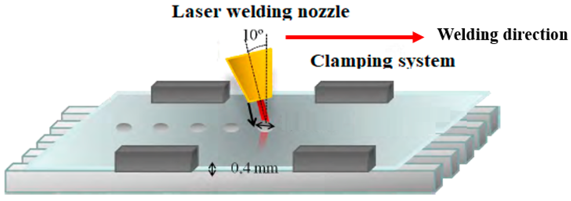
The thickness of the plates for all the welding experiments was 0.4 mm as was the laser beam diameter. This value is considered typical for both magnitudes, thickness and diameter. In addition, the beam diameter is considered to be strongly related with the depth and size of the welding pool. If the thickness of the plate is shorter than the beam diameter, the material melts before having the possibility of reaching the keyhole regime; however, if the thickness is larger than the beam diameter, it is impossible to make the welding pool traverse the material maintaining the conduction regime. Consequently, the coincidence between the beam diameter and the thickness of the plate permits the different welding modes to be studied for the same configuration of the process. Figure 1 shows a diagram of the process to study the laser pulses. The nozzle has an inclination of 10° with respect to the vertical direction to avoid back reflection to the machine of the reflected radiation. In the case of the welding of a ferric plate with an austenitic one, the plates are overlapped.
2.1. Relation of the Parameters of the Laser Pulse with the Effect on the Material
A pulsed welding is the result of combining several process parameters. They are the beam diameter, Ø, the laser power, P, the pulse duration, t, the repetition pulses frequency, f, and the time within each pulse during which the laser is releasing radiation, known as duty factor (DF). In the case of dynamic pulses, the traversing speed of the laser source, v, constitutes an additional variable. The energy of the pulse, E, can be calculated as the product of the power and the pulse duration.
The measurement of the melted region and the heat-affected zone obtained after shooting the material with pulses with different combination of parameters allows for analyzing the capabilities of the pulses to modulate the welding regime, conduction, or keyhole, and the subsequent consequences of it. One of these is the relation between the area affected by the pulse in the face and bottom of the plate, which determines the overlapping distance between consecutive pulses. A series of pulses to characterize this relation has been carried out with the parameters shown in Table 2.
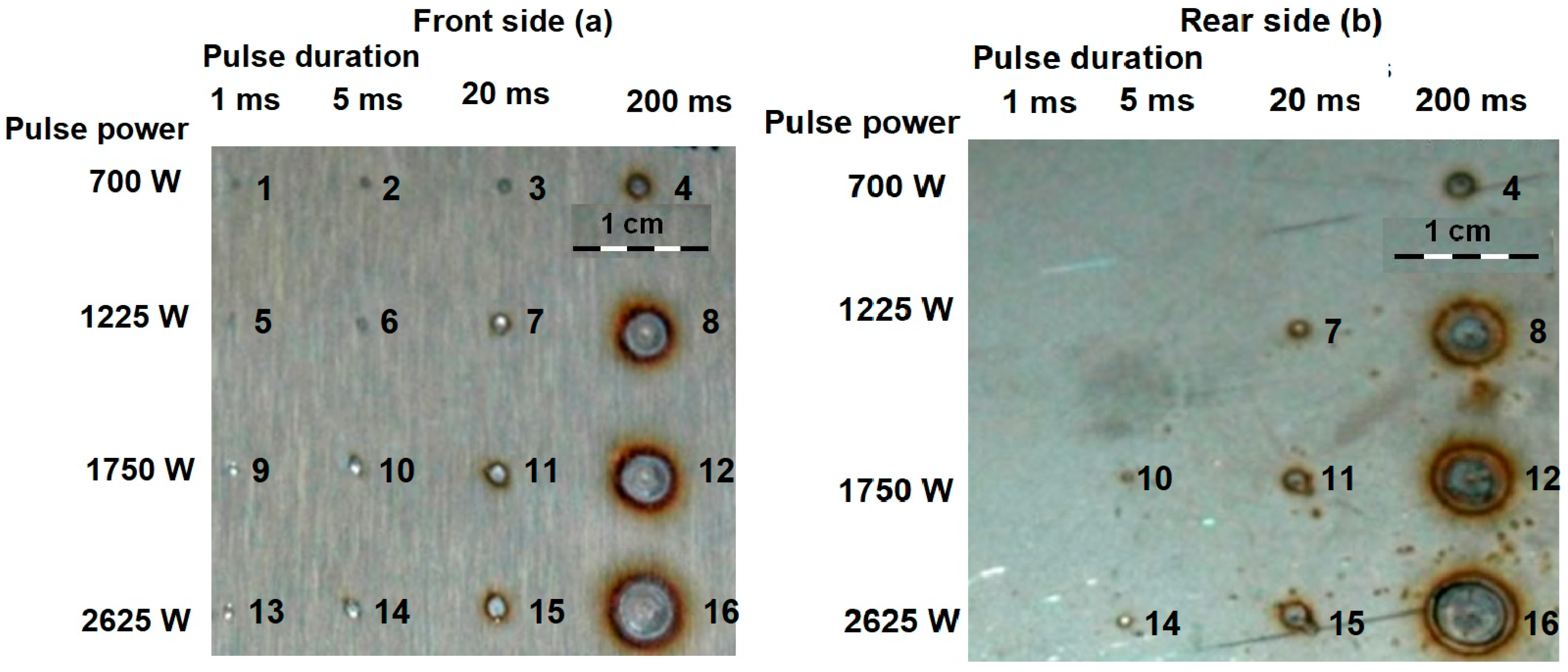
Figure 2 shows the effect on the material in the directly irradiated side Figure 2a and in the bottom Figure 2b, using the parameters from Table 2. Note that at the bottom, depending on the pulse parameters, some affected areas are not visible.
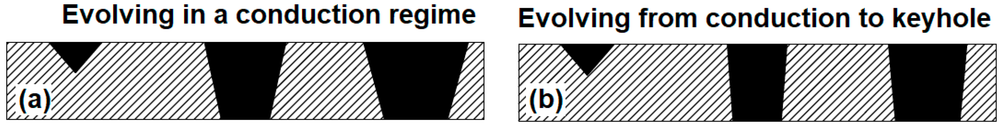
The range of powers and pulse durations in Figure 2 goes from having no apparent effect on the material to having traversed completely the thickness of the plate and achieved an affected circumference of almost 1 cm diameter, and, therefore, several times larger than the laser beam diameter of 0.4 mm. In addition to providing working windows about the parameters for the laser pulses, the tests in Figure 2 were able to highlight the mechanism governing heat conduction in the material in each regime. Considering the pulse corresponding to a power of 2625 W and a duration of 20 ms, it has taken place in keyhole regime. This can be stated from observing that it has the same diameter in the face and the bottom, since the plasma grows predominantly in the same direction as the laser-beam propagation. The same level of power of 2625 W, in combination with a pulse duration of 5 ms, has not surpassed the threshold energy to create plasma, and, in this case, the bottom diameter is shorter than the one at the face. The comparison between both situations allows for establishing the geometrical pattern of the cross section of the region affected by the laser pulse in relation with the welding regime. Figure 3 represents schematically the cross section of the welding pool by increasing the energy of the laser pulses always evolving in a conduction regime (left side, from left to right), and evolving from a conduction regime to a keyhole regime (right side, from left to right). While increments of energy in a conduction regime are associated with the growth of both the face and bottom-melted diameters proportionally to the level of energy, when the transition to keyhole regime happens, heat conduction occurs predominantly in the vertical direction, and the melted diameter at the face tends to stabilize, while the bottom affected diameter approaches the face one.
From Figure 3 it can be seen that in the keyhole regime the welding pool has a more vertical disposition than in the conduction regime. This behavior gives some patterns to minimize the thermal impact in the building of a continuous seam. If the requirement is to achieve a continuously welded seam in the directly irradiated face of a joint and no matter if the opposite face has only separated welded points, conduction regime is acceptable. However, if continuity has to occur in the bottom of the joint, the use of a conduction regime would lead to a tremendous overheating of the directly irradiated face since the bottom-melted diameter is always going to be shorter than the one at the face. Something similar happens with the heat-affected zone. Nevertheless, by using a keyhole regime, the high absorption of the energy in vertical direction makes the bottom diameter approach the one at the face of the plate, and the overheating to achieve bottom continuity is significantly reduced.
These considerations are reinforced if the heat-affected zone is analyzed in Figure 2. The pulse with a power of 2625 W and a duration of 200 ms has happened in the keyhole regime given the coincidence between the face- and bottom-melted areas. The heat-affected zone in the bottom of the pulse can be seen as an oxide circle around the melted region. In the case of the bottom of the pulse for the cases of 1750 W, 200 ms and 1225, 200 ms, it reveals that these pulses have passed in conduction regime, because of their shorter diameters in comparison with the face. Their oxide circle is bigger compared with the melted area than in the case of the pulse happening in the keyhole regime, where the oxide circle approaches the melted area. Once again, the higher energy efficiency of the keyhole regime led to a larger amount of energy concentrated in the welding pool instead of overheating the surrounding material.
The fundamentals to select the real affected diameter instead of the nominal diameter of the laser beam as a reference to establish the overlapping between consecutive pulses is also clear from Figure 2. For all the levels of power, the affected area in the material always grows with the pulse duration, or, in other words, with the energy of the pulse. Table 3 contains the process parameters used to characterize the effect of the pulses frequency and the DF with 1750 W of power.
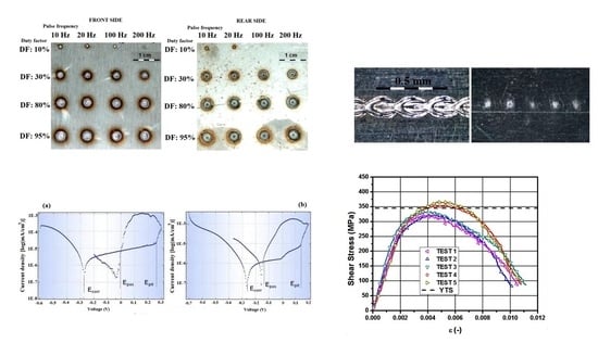
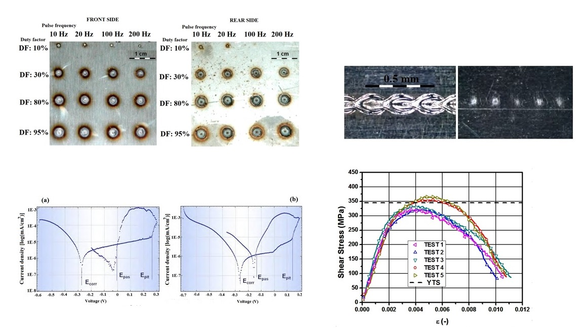
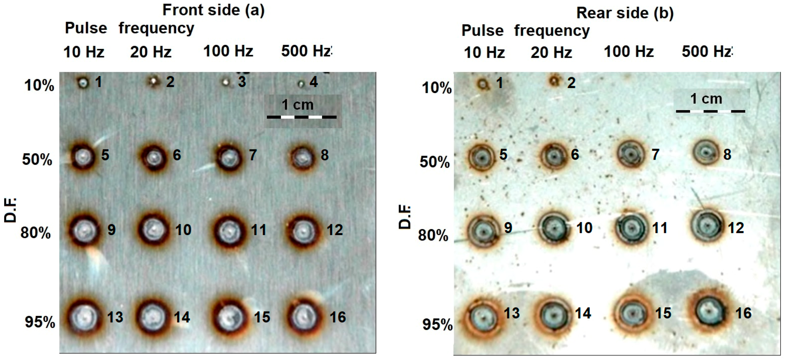
Figure 4 shows the effect of the pulse repetition frequency and the duty-factor percentage on the treated material for a power of 1750 W and a total duration of 200 ms. Note that at the bottom, depending on the pulse parameters, some affected areas are not visible.
The effect of the duty factor is clear from Figure 4. Since it is the percentage of the duration of the pulse during which the laser is on, the larger value the duty factor has, the larger amount of energy supplied and, consequently, a big area of the material is affected by either the heat-affected zone or welding pool. The pulse repetition frequency represents the number of pulses per second whatever the value of the duty factor is. High frequencies tend to hinder the transition from conduction to keyhole regime. It can be seen in Figure 4, comparing, for instance, the bottom affected area of the pulses with a duty factor of 50% and frequencies of 20 Hz and 500 Hz. The melted area in comparison with the total affected area (surrounded by an oxide circumference) is bigger for the case with the lowest frequency. A similar behavior can be observed for the remaining tests. The physical basis for this behavior is related with the stability of the plasma, which is more favored with intermediate values of frequency.
The transition of the welding regime, from conduction to keyhole, and the dimensions of the heat-affected zone and the melted area can be modulated, therefore, by adjusting the pulse parameters. Qualitatively, the achievement of a joint with high mechanical resistance, associated with high penetration of the welding pool, and minimum thermal impact, is related with the obtaining of the keyhole regime. It has been shown to be achieved with relatively high values of power and energy of the pulse, and intermediate values of pulse repetition frequency, which, in turn, can be readjusted by means of the duty factor. After this phenomenological approximation to the most favorable pulse parameters, the following step is a quantitative characterization of them, in static and dynamic conditions, to get particular values to introduce in the overlapping factor (OF) formula [18], in order to get a continuous joint with overlapped pulses with minimum thermal impact.
2.2. Calculation of the Overlapping Distance
The OF is a quantification of the separation between consecutive pulses in relation to diameter of the laser beam, in a classical approach, or in relation to the real dimensions of the affected area in the material affected, in an approach focused on the energy optimization of the joint. In a previous study by the authors [20], a methodology to calculate the overlapping distance in an energy-optimized way was presented. The current section highlights the main aspects of this methodology in the context of its application to the laser welding of dissimilar steels.
The overlapping factor can be calculated for either static of dynamic pulses. In the static case, the overlapping factor can be trivially calculated as Equation (1) indicates, where Ø is the diameter of the laser beam and D is the length of the first pulse that was not covered by the next one:
OF = D/Ø,
The formula for dynamic pulses must instead consider the elongation of the pulse due to the movement of the thermal source along a distance, L, equal to the diameter of the laser beam, Ø, plus the product of the process speed, v, by the time, t; the term S represents the length of the first pulse that was not covered by the constative one. Equation (2) offers the overlapping factor for dynamic pulses:
OF = (L − S)/L.
Considering the procedure in Reference [17], Equation (2) can be operated to make it explicitly dependent on the parameters to define the laser pulse, as Equation (3) shows, where f is the pulse repetition frequency and DF is the duty factor of the pulse:
OF = 1− (v/f)/[Ø + (v × DF)/f].
A continuous joint by means of overlapped pulses has minimal thermal impact when the overlapping factor is equal to zero, meaning that the contour of each affected area on the material is strictly tangential to the following one. Since Equation (3) is indeterminate given the number of variables, some additional considerations and assumptions have to be introduced as a function of particular requirements, to get the most suitable election of parameters.
Considering the construction of a linear joint along a given length, L, the linear energy, EL can be defined as the energy of each pulse, E, multiplied by the total number of pulses, NP, needed to cover the prescribed length, as indicated by Equation (4):
EL = E × NP/L.
The number of pulses needed to cover a given length depends, in turn, on the real dimensions of the affected area in the material.
From the experiments in Reference [20], prescribed levels of energy were obtained by means of different combinations of power and pulse duration. The cases with pulses of relatively long duration (in the order of 15 ms and 10 ms) needed a relatively short amount of power to achieve a given level of energy. In these cases, the growth of the bottom melted diameter followed a proportional tendency with the increase of power, as typically happens in conduction regimes. When the same levels of energy were obtained with a shorter pulse duration, the amount of power increased, while the growth of the bottom diameter of the pulse followed an asymptotic behavior (stabilization of the size of the diameter despite increasing the power of the laser pulses), which is associated with a typical keyhole regime, where energy absorption happens predominantly in the vertical direction. It means that, for the considered energy levels, the evolution from conduction to keyhole regime happened with pulse durations between 5 ms and 10 ms for the working material used in that study.
Having obtained experimentally particular values for static pulses associated with the different welding regimes, the next step in Reference [20] was to study the effect of the same values of the pulse parameters in dynamic conditions, where the thermal source experiences a linear movement during the releasing of the laser radiation. Considering the energy levels used for the characterization of static pulses, intermediate values of energy, in the range 10–12 J, were reproduced in dynamic conditions analyzing both the effect of a relatively low advancing speed of 100 mm/s and a relatively high advancing speed of 200 mm/s.
For pulses with a relatively low process speed, the obtained bottom diameter was larger than the equivalent static pulse with the same energy and pulse duration. It is associated to the relation between power density. While with static pulses a saturation effect happens due to a plasma-shielding effect, in the case of 100 mm/s, the dissipation of the plasma is more favored and the shielding effect disappears. Additionally, the speed of the process provides momentum to the welding pool, which assists penetration in the bath. For the case of the highest process speed, 200 mm/s, the bottom diameter had a tendency to diminish. In this case, the higher speed of the process does not favor the stability of the plasma, and, consequently the penetration is poorer.
In the case with the shortest pulse duration, when it was applied with a speed of 100 mm/s, the profile corresponds to a typical keyhole behavior with a small heat-affected zone and high penetration. The movement of the welding pool made the molten metal displace to the sides of the welding. When the linear speed increased, some distortion appeared affecting the regularity of the welding pool and the profilometry. This is due to the appearance of projections from the destabilization of the plasma. This phenomenon may lead to mechanical problems like pores, irregularities, and spattering. The situation in Reference [20] where a level of energy of 12 J was achieved with a pulse duration of 10 ms gave place to a keyhole with lower energy concentration than the case with 5 ms. In these circumstances, there is no a surplus of energy capable of maintaining the plasma pressure enough to laterally displace the molten mass. Because of this, the welding pool decreases in the transversal direction to the advancing direction, when the speed increases. The contraction of the keyhole is associated to a poorer conduction of the heat to the base of the welding pool, affecting the depth reached by the welding. However, the narrowing of the keyhole has the advantage of preventing the welding pool from creating spattering and drops.
3. Results
A practical case for the welding of an AISI 430Ti plate with an AISI 301 plate was carried out. It was based on a real case from a home-appliance device where the AISI 301 plate is in a visible part of the device while the AISI 430Ti corresponds to a hidden surface of the device. In this way, the laser pulses are applied on the hidden surface with several requirements: full penetration from the ferritic plate to the austenitic plate, for the sake of mechanical resistance; tightness, implying continuity of the joint; and, from an esthetical point of view, avoiding significant welding marks in the seen face. Since the laser pulses are applied on the ferritic side, the energy characterization of the static and dynamic pulses from the previous section were considered to provide valid data to calculate the overlapping factor.
3.1. Continuous Seam with Minimal Thermal Impact
The process to get an energy-optimized welding starts by building a continuous joint capable of meeting the requirements of penetration and tightness, obtaining a reference for the laser power. From this reference, and considering the effective dimensions of the interaction area obtained in the previous sections for pulses obtained with different combinations of power and pulse duration, the only unknown in the overlapping factor formula (see Equation (3) in Section 2.2) is the frequency. If it is solved, the resulting joint with pulses made with all the parameters from the formula leads to a continuous joint, where each pulse is tangent to the surrounding ones, and, therefore, with minimal thermal impact.
The calculation of the pulse repetition frequency starts with the selection of the dynamic pulses with minimum energy per length unit. Considering the results for the laser pulses in Reference [20] the pulse with an energy level of 10 J, a pulse duration of 5 ms, and an advancing speed of 200 mm/s is capable of melting the bottom of the irradiated plate with a diameter of approximately 0.5 mm. The selection of the pulse with the highest speed ensures the minimization of the energy per length unit on the irradiated face since the higher the speed is, the longer the distance along which it is spread. Substituting the numerical values in Equation (3), establishing the bottom overlapping factor equal to zero and using I.S. units, leads to Equation (5):
OF = 0 = 1 − (0.2/f)/[0.0005 + (0.2 × DF)/f].
The duty factor is related with the pulse duration and the pulse repetition frequency by Equation (6):
DF = t/(1/f).
Introducing Equation (6) in (5) and clearing f, it has a value of f = 133 Hz, which is the value used for the pulsed joint of Figure 5, where there are no apparent traces of corrosion.
3.2. Preservation of the Corrosion Resistance
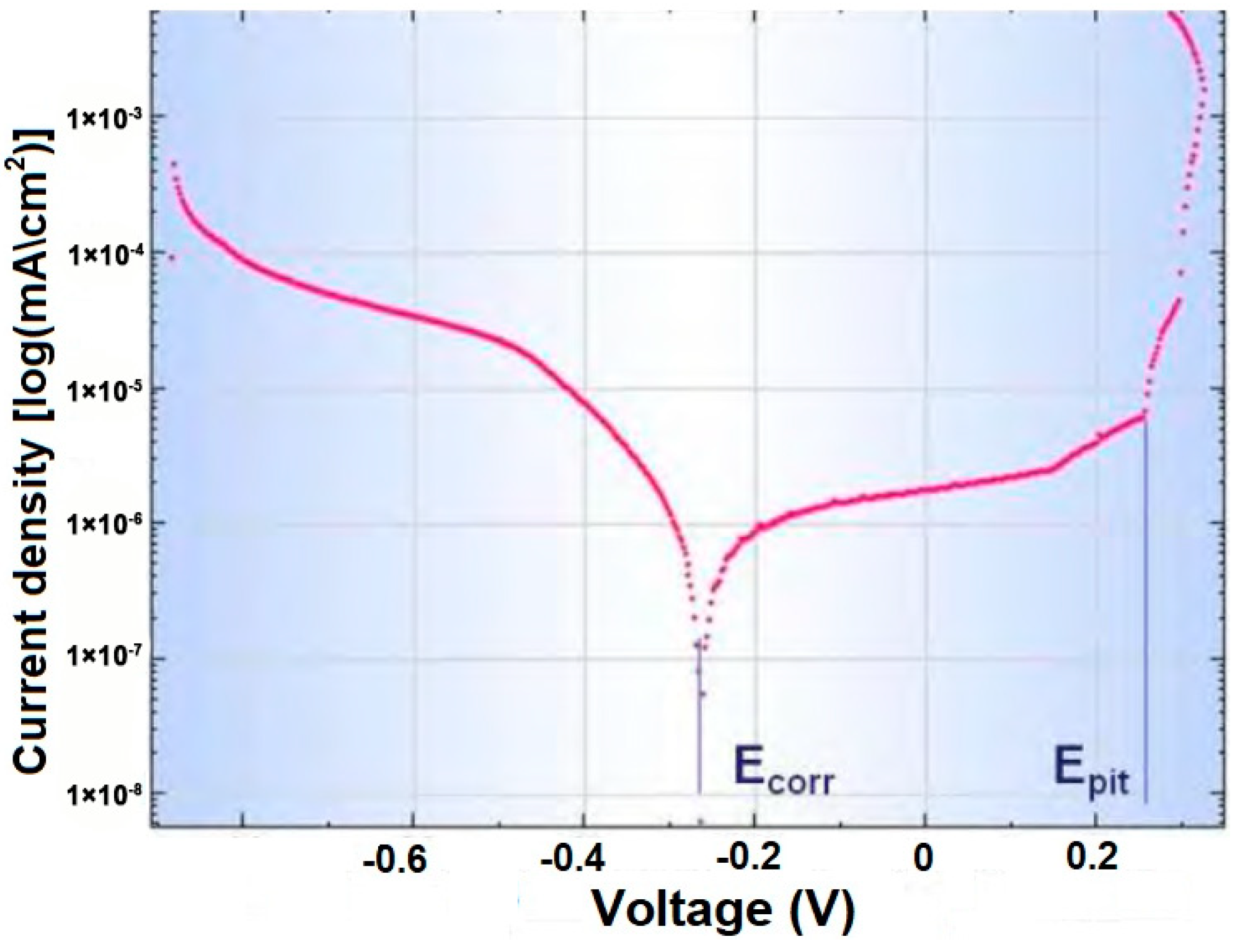
The corrosion resistance can be quantitatively evaluated by means of potentiostatic curves [21], also known as Tafel curves. The potentiostat is a device that integrates electronic hardware and electrodes with the aim of generating an anodic zone in the metal to be studied, thus promoting its corrosion. In these conditions, an electron current appears, which the equipment detects as intensity. Additionally, by changing the anodic, potential different conditions can be tested. The most common test is known as polarization with simultaneous registration of the intensity. To carry out the corrosion test, all the samples were cleaned with acetone after the welding process. A circular area with 8 mm of diameter was studied in each case. For the treated material, this area was allocated directly on the welded zone of the ferritic plate, and on the opposite side in the case of the austenitic plate. Both the remelted material and the HAZ were included in the analyses. A solution of sodium chloride into pure water was used as electrolyte. Figure 6 shows the Tafel curve corresponding to the AISI 430Ti ferritic steel in the initial conditions that will be used as the reference.
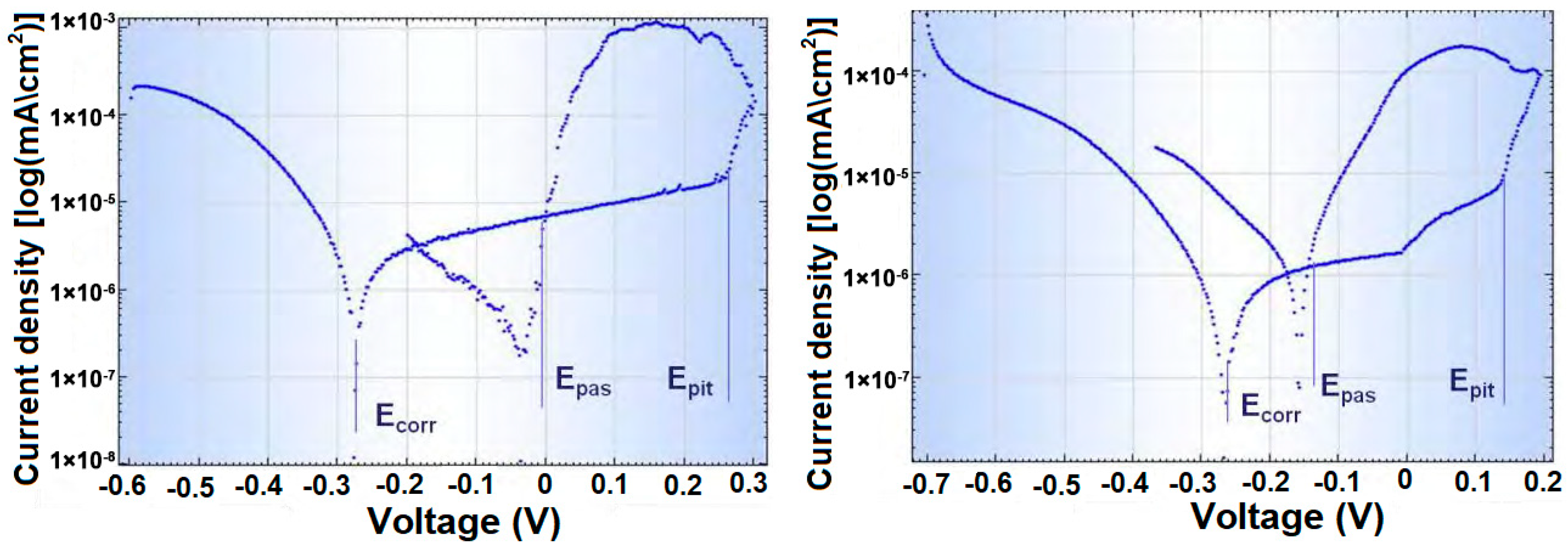
Figure 7 shows the Tafel curves corresponding to the AISI 301 steel after undergoing the optimized laser welding Figure 7a and the Tafel curve corresponding to the AISI 430Ti steel in the same conditions Figure 7b. In all the plots in Figure 6 and Figure 7, the term Ecorr represents the critical corrosion potential of the material at a given intensity, the term Epit is the critical potential for corrosion by the mechanism of pitting at a given intensity, and Epas is the potential of repassivation of the material, when the protective passive layer appears after having experienced corrosion by the mechanism of pitting.
The corrosion resistance of a metal can be related with the difference Ecorr − Epit. Considering the AISI 430Ti steel as a reference, since it is a stainless steel, its value for this difference is approximately of 0.5 V in absolute value. The AISI 301 steel after the welding process shows a difference in absolute value of approximately 0.54 V higher than the untreated ferritic steel. The studied difference for the AISI 430Ti steel after welding has an absolute value of 0.45 V, slightly smaller than the untreated material, which can be considered acceptable. The difference Epas – Epit indicates the capability of the material to regenerate the passive protective layer after having experienced corrosion by the mechanism of pitting. The shorter this difference is, the faster the protective layer grows. Although it is not affected by the welding process, in Figure 7 it can be seen that this difference is more favorable for the case of the austenitic steel than for the ferritic steel, as was expected.
Additionally, given the different corrosion potential of each material, the presence of a galvanic couple in the union of them is going to be always present. The potential of this couple has been measured in 0.24 V, which, not being very high, would require specific caution in the industrial application of this union.
3.3. Metallographic Analysis of the Cross Section
In order to make clear the effect of the energy-optimized parameters on the microstructure of the welded materials, also considering the examination of the penetration of the melt pool through the plates, cross sections from the continuous seam presented in Section 3.1 were analyzed. The microstructure of the welding of dissimilar steels by means of conventional techniques is presented in References [22,23].
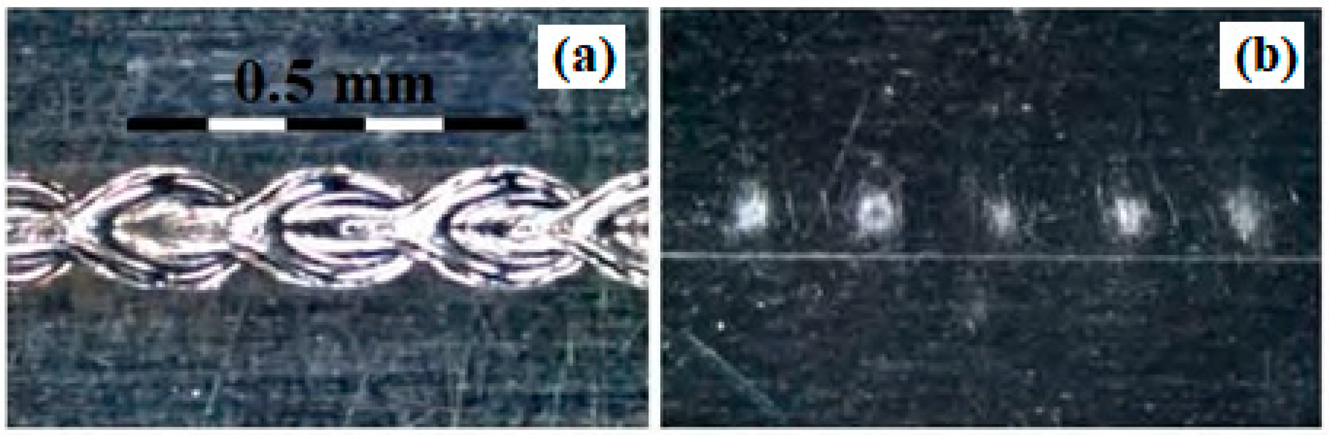
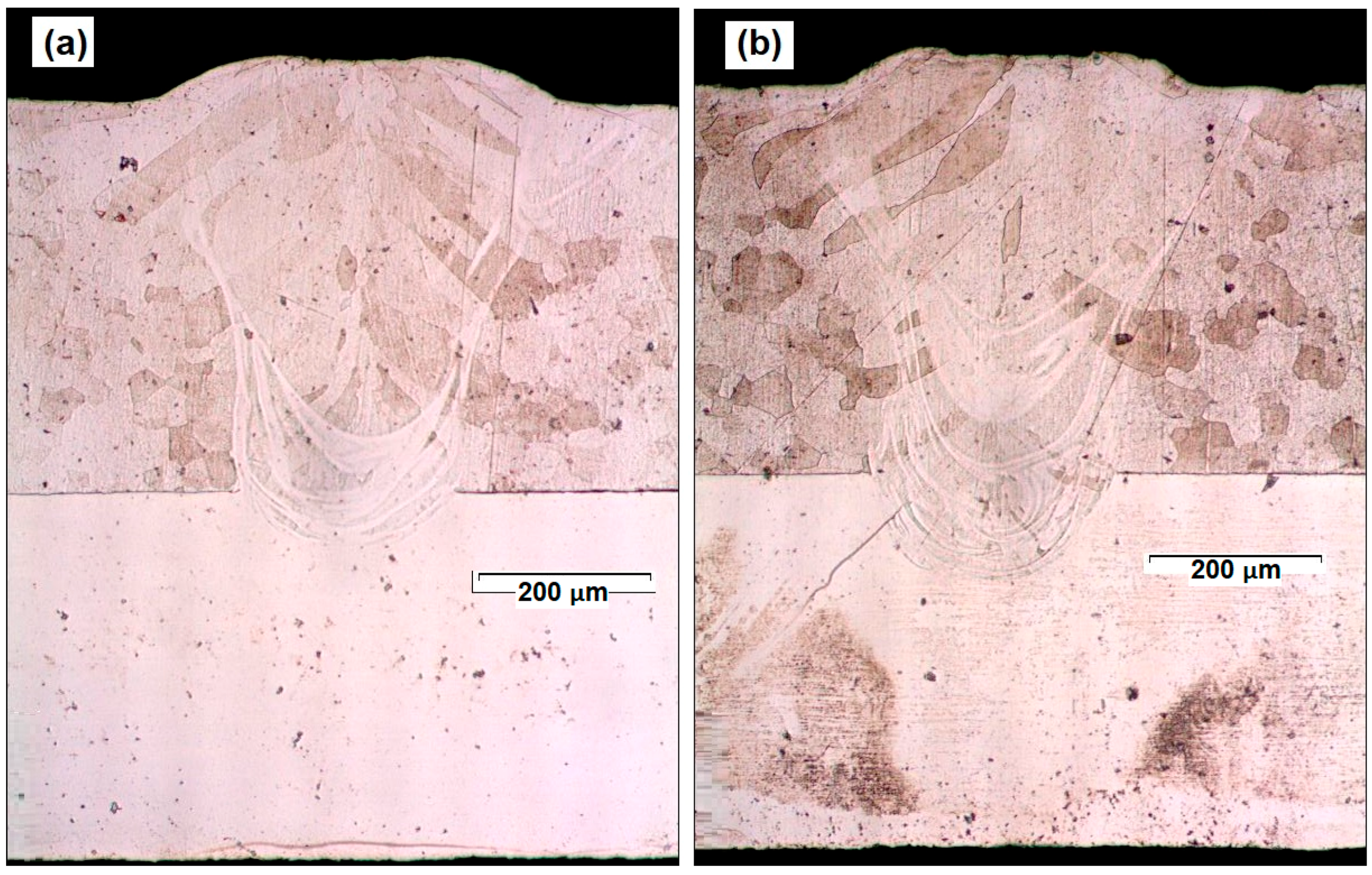
Samples were cut by means of electrical discharge machining (EDM). Cross sections were mirror polished and etched with aqua regia to highlight the microscopic grains. Given the minor corrosion resistance of the AISI 430Ti ferritic steel compared to the austenitic side of the welding, the chemical etching was stopped when the microstructure of the ferritic side of the cross section was clear. It allowed the microstructure of the ferritic side to be clearly revealed, as well as the penetration of the laser pulse and the transition between the different regions of the welding. Figure 8 shows two microscopic images of different cross sections taken at different positions along the weld. Figure 8a corresponds to a position close to the beginning of the weld, while Figure 8b corresponds to a position close to the ending of the weld.
In Figure 8, the effect of the laser pulse can be seen clearly, making the melt pool traverse from the top of the ferritic side to the austenitic side. The gap that separates both plates has been successfully joined by the effect of the laser pulse in all the regions reached by the meet pool. There is a slight improvement in the penetration in the position close to the end of the joint associated with the heating of the workpiece.
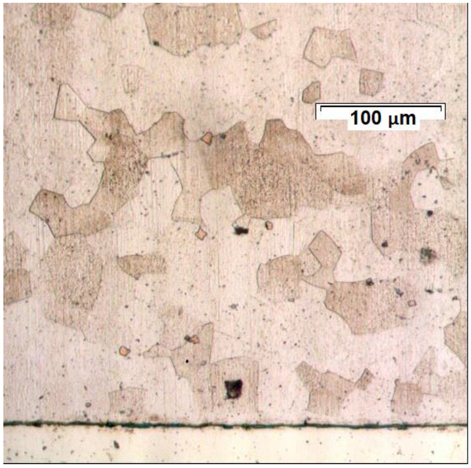
The columnar structure of the ferrite grains in the welded area reveals the direction of the heat diffusion at the boundaries of the melting pool. The columnar structure gives place to equiaxial grains at a relatively close distance of the melted material, which confirms that the proposed methodology is associated to a reduced HAZ. Figure 9 shows a detailed view of the base material to serve as a reference.
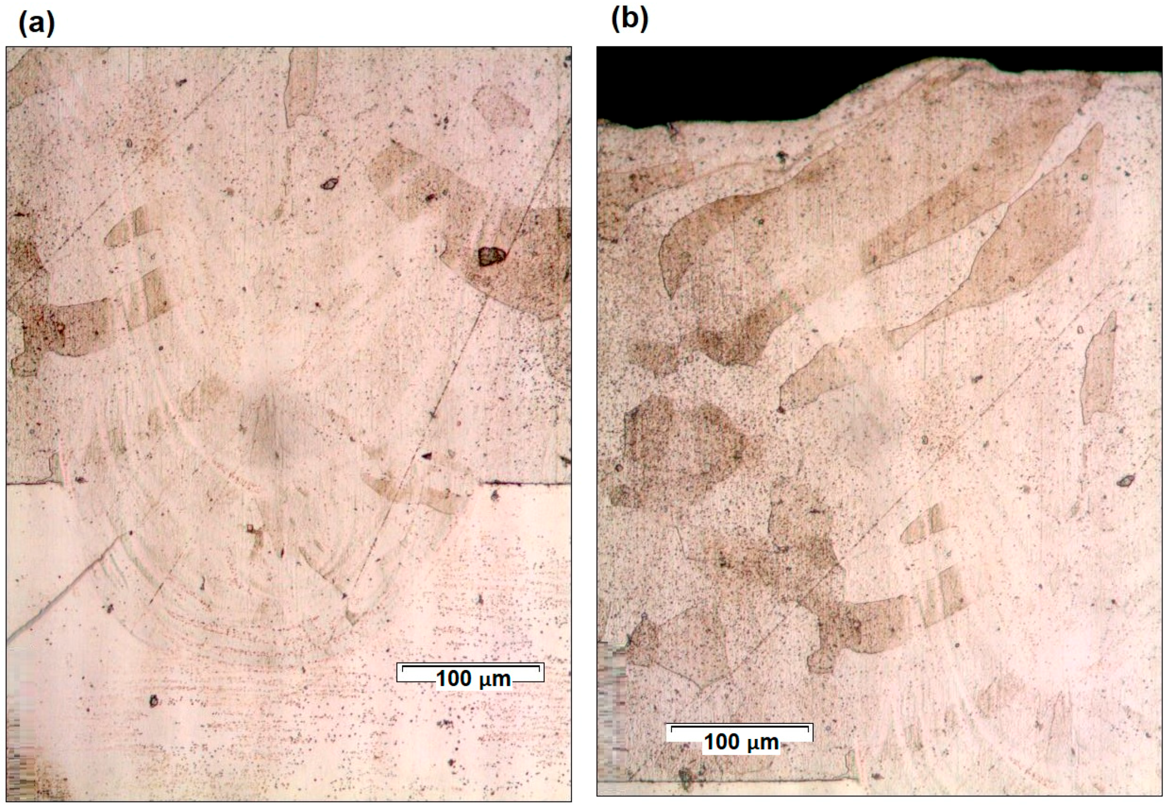
Figure 10a,b shows, respectively, a detailed view of the maximum penetration and of the HAZ from the cross section in Figure 8b.
From Figure 10a, the maximum penetration of the laser pulse into the austenitic plate has a length of about 150 µm. Considering some slight influence derived from the heating of the material during the development of the seam, the penetration of the laser pulse into the austenitic side (which is never directly shot) can be estimated in a range from 30% to 40% of its total thickness. From Figure 10b, equiaxial grains at about 100 µm of the remelted material can be seen, showing, in this way, the limited extension of the HAZ.
3.4. Mechanical Analysis of the Optimized Seam
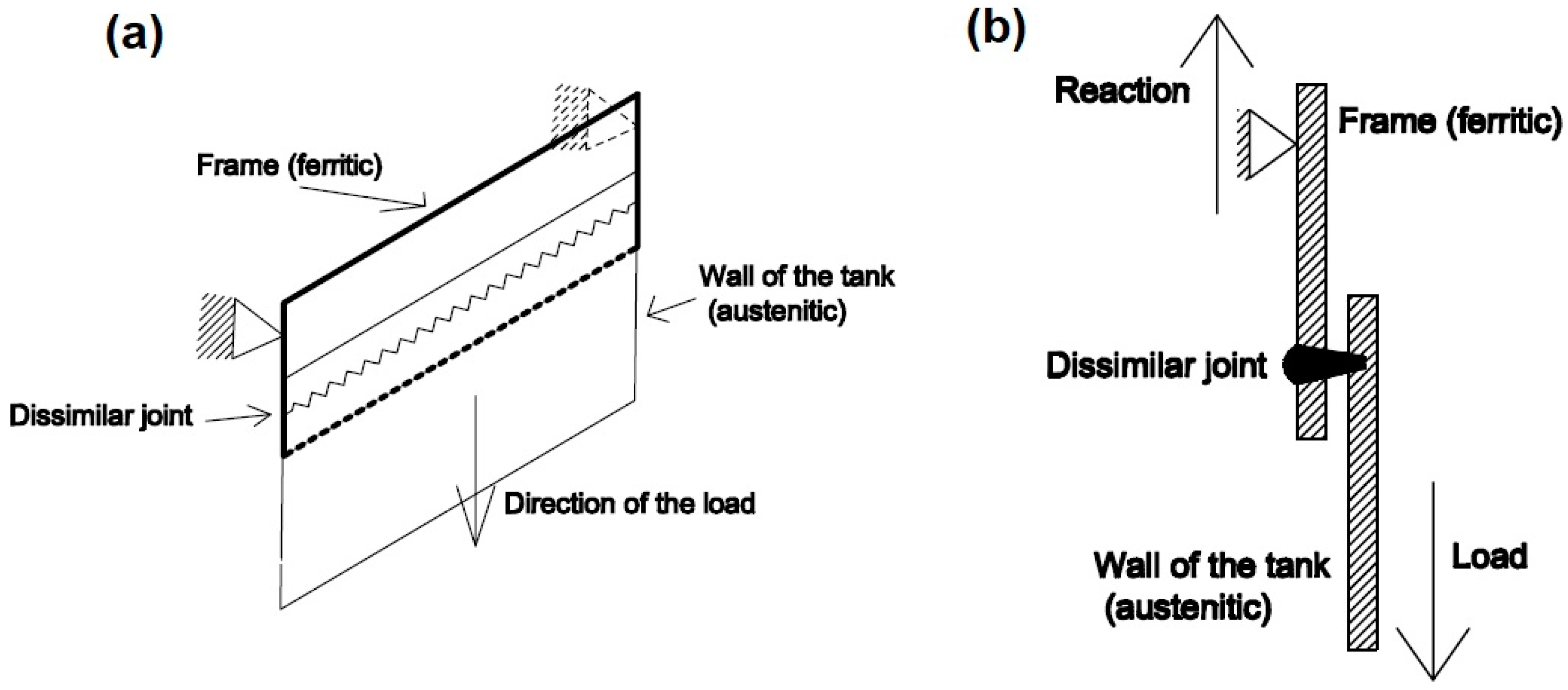
The evaluation of the mechanical performance of a welded joint depends on the way in which it is going to be applied. Some mechanical tests for the characterization of the welding of dissimilar steels can be found in Reference [24]. In the present work, the mechanical characterization of the optimized joint has been carried out considering the objective of the present work to apply the welding of dissimilar steels to the home-appliance industry. In this way, an internal tank of the device, thought to be accessible to the user, can be made of uncoated austenitic steel for corrosion and esthetical proposes. The frame of the machine, nevertheless, is conditioned mainly by corrosion and economical requirements. The union of the tank with the frame of the machine is the region where the optimized dissimilar joint is applied. Figure 11a shows a diagram of the assembly between the tank and the frame of a hypothetical home-appliance machine and Figure 11b shows a cross section of it considering the forces on the joint.
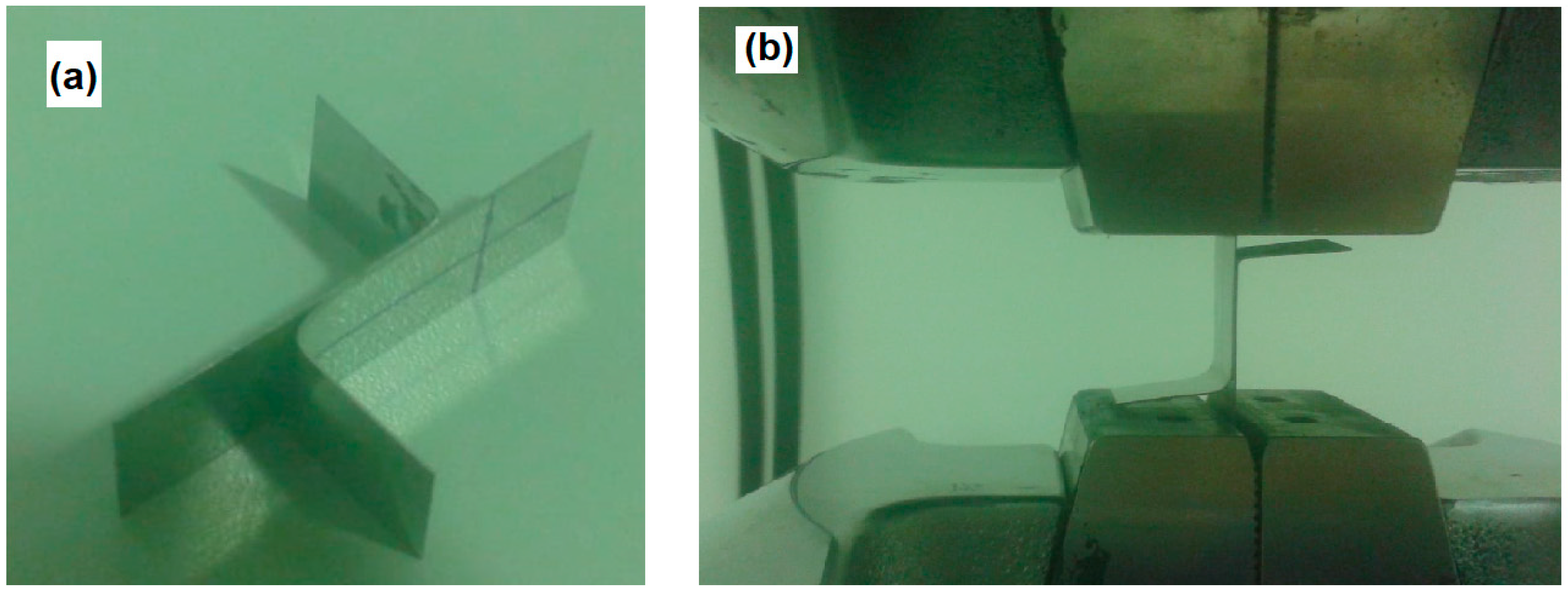
To reproduce the particular conditions of the joint in service, a universal testing machine has been used. A total of five samples of 1 cm of width were obtained from the optimized joint and tested to check the uniformity of the mechanical response along the joint. Figure 12a shows one of the samples. Each of them was fixed in the ferritic side to the superior grip of the machine and in the austenitic part to the inferior part of the machine, as shown in Figure 12b.
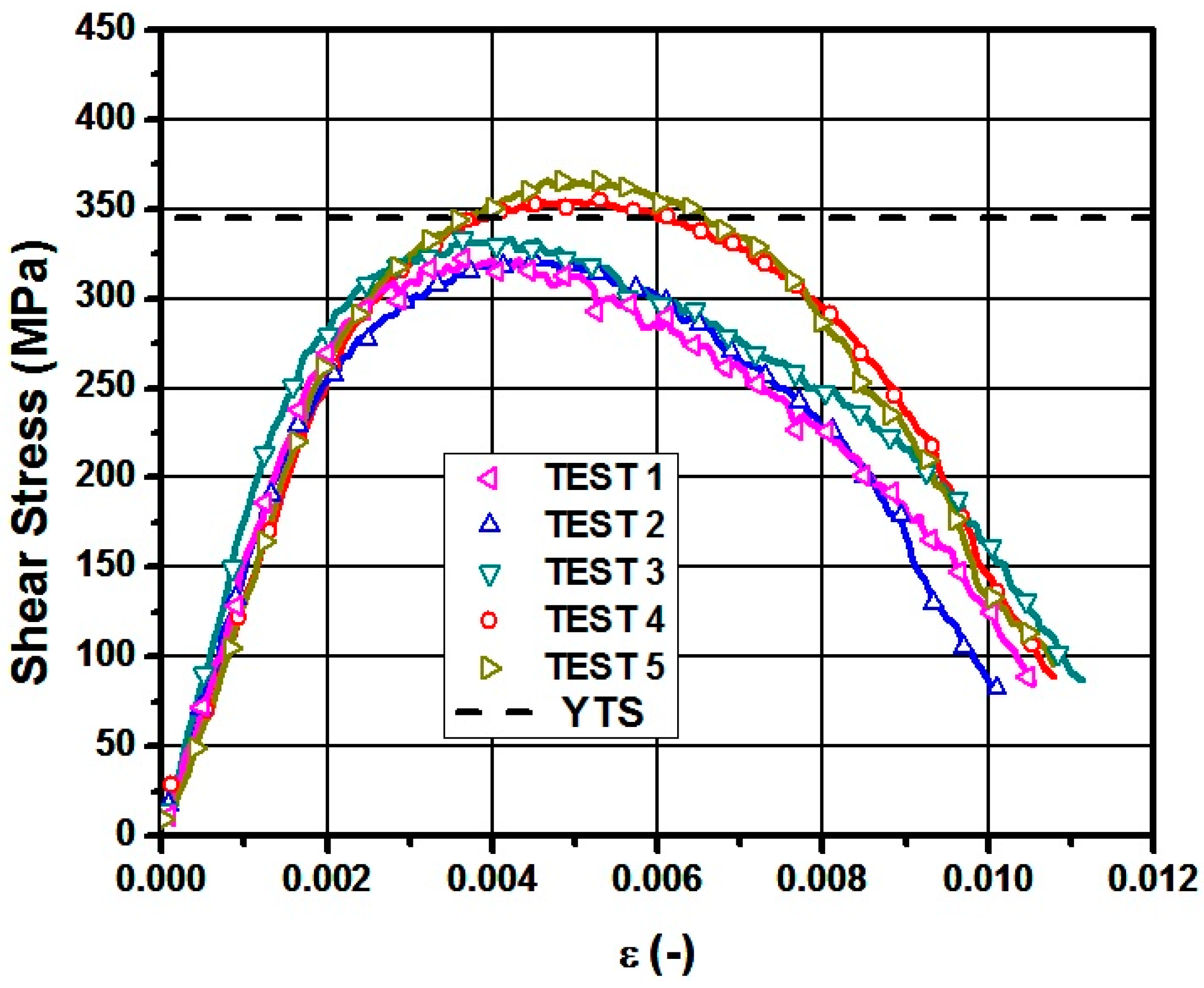
Despite the test having a global tensile nature, the joint is submitted to shear stress. In this way Figure 13 shows the curve of the shear stress in the welding as a function of deformation. The area used to calculate the shear stress corresponds to the width of the sample multiplied by height of the union at the level of the gap between the plates, which can be determined from Figure 10. All samples broke in the joint.
From Figure 13 it can be seen that the experimental YTS of the joint lies around 300 MPa, while the value from the original steel is 345 MPa. It implies that the proposed weld has 87% of the YTS of the original material. The UTS of the proposed optimized welding varies from a value around 325 MPa for tests 1–3, to around 360 MPa for tests 5,6. This difference can be related with the position of the different samples along the joint. While the first tests corresponded to a position close to the beginning of the joint, the last ones were closer to the center of it, where the heating of the material has favored the development of the welding. The UTS of the original AISI 430Ti steel is 517 MPa, which implies that the joint reached a value that ranged from 63% to 70% of the UTS of the original material. The obtained values are considered acceptable at the expense of the minimal thermal impact of the optimized joint and its advantages in its corrosion resistance. The difference of the resistance of the joint in comparison with the resistance of the base material can be associated with the lack of full penetration of the laser pulses into the rear plate. This idea can be reinforced by the fact that the in the last tests—tests 4 and 5—a UTS value closer to the value of the base material was achieved thanks to the fact that the heating of the plates favored a slightly deeper penetration (see Figure 8. Given the uncertainty associated with the measurement of the area as a succession of points, the consideration of a rectangular shape can be assumed as a characterization of the properties of the joint with some extra security margin.
4. Discussion
The results show the feasibility of the welding of dissimilar stainless steels with minimum thermal impact. Figure 5 and the related analyses highlight the capabilities of the parameters in the definition of the laser pulses to modulate the welding regime and to achieve the highest energy efficiency in the vertical direction to penetrate the plates without overheating them with the keyhole regime.
The Tafel curves are chosen as an evaluation of the corrosion resistance. It is shown that the materials on both sides of the welded joint show similar or even better behavior than the ferritic untreated steel taken as reference, despite having undergone full penetration by the dynamic pulses.
The calculation of the overlapping factor considering the real dimensions of the affected material is a key factor to minimize the thermal impact since, as has been demonstrated, the diameter of the laser beam may lead to differently affected dimensions depending on the pulse parameters. Nevertheless, the characterization of the affected dimensions for a given material requires a previous experimental campaign to relate the affected area with the pulse parameters. This preliminary step, not being necessarily expensive or time consuming, could be substituted by means of numerical simulation studying the phenomena associated to the heat conduction and the plasma dynamics [12,25], involving less experimental work, but having to deal with high computational times and complexity.
The microstructure of the optimized joint has been analyzed. This analysis confirms the small dimensions of the HAZ associated with a minimal thermal impact of the welding. The melt pool has penetrated from the ferritic side to the austenitic side. Some increase in the penetration is observed because of the heating of the material during the development of the joint.
The mechanical response of the joint has been characterized by comparison with the YTS and UTS values from the untreated material. It has been proven that having a slight deterioration of the YTS and UTS in the joint, in the worst case the UTS represents 68% of the original material, which, considering the focus on the minimum thermal impact of the welding, can be considered satisfactory.
Author Contributions
F.C. contributed to the analysis of the physical phenomena associated with the different regimes of welding and prepared the explanation of the physics basis and experimental procedures that have given place to the present work. A.T. designed, conducted, and carried out all the experiments of the present work, as well as interpreting the results of the experiments. Á.G.-B. provided technical guidance during all the stages of development of the present work, and helped to prepare the presentation of the results and to explain them. M.D. carried out the different experimental tests and helped to understand the information. I.A. assisted during the experimental process and collaborated in the interpretation of the results. J.L.O. is the leader of the research group and he has defined the tasks and scope of the project in which the present work is framed. He has also contributed with fundamental physics guidance during all the stages of the work.
Acknowledgments
Work partly supported by BSH Electrodomésticos España S.A.
Conflicts of Interest
The authors declare no conflict of interest.
References
- Schubert, E.; Klassen, M.; Zerner, I.; Walz, C.; Sepold, G. Light-weight structures produced by laser beam joining for future applications in automobile and aerospace industry. J. Mater. Process. Technol. 2001, 115, 2–8. [Google Scholar] [CrossRef]
- Tarn, T.-J.; Chen, S.-B.; Zhou, C. Robotic Welding, Intelligence and Automation, 1st ed.; Springer: Berlin, Germany, 2007; pp. 105–249. ISBN 978-3-540-73373-7. [Google Scholar]
- Barnes, T.A.; Pashby, I.R. Joining techniques for aluminium spaceframes used in automobiles: Part I—Solid and liquid phase welding. J. Mater. Process. Tech. 2000, 99, 62–71. [Google Scholar] [CrossRef]
- Ishak, M.; Shah, L.H.; Aisha, I.S.R.; Hafizi, W.; Islam, M.R. Study of resistance spot welding between AISI 301 stainless steel and AISI 1020 carbon steel dissimilar alloys. J. Mech. Eng. Sci. 2014, 6, 793–806. [Google Scholar] [CrossRef]
- Sedriks, A.J. Corrosion of Stainless Steel, 2nd ed.; John Wiley and Sons, Inc.: New York, NY, USA, 1996; pp. 13–79. ISBN 978-0471007920. [Google Scholar]
- Sun, Z. Feasibility of producing ferritic/austenitic dissimilar metal fronts by high energy density laser beam process. Int. J. Press. Vessel. Pip. 1996, 68, 153–160. [Google Scholar] [CrossRef]
- García, A.; Salas, R.; Centeno, L.; Velázquez del Rosario, A. Metalurgia de uniones soldadas de aceros disímiles (ASTM A240–A537) y comportamiento mecánico ante cargas monotónica y cíclica. Rev. Latinoam. Metal. Mater. 2012, 32, 36–48. [Google Scholar]
- Harjo, S.; Tomota, Y.; Ono, M. Measurements of thermal residual elastic strains in ferrite–austenite Fe–Cr–Ni alloys by neutron and X-ray diffractions. Act. Mater. 1998, 47, 353–362. [Google Scholar] [CrossRef]
- Reddy, G.M.; Rao, K.S. Microstructure and mechanical properties of similar and dissimilar stainless steel electron beam and friction welds. Int. J. Adv. Manuf. Technol. 2009, 45, 875–888. [Google Scholar] [CrossRef]
- Hsieh, C.-C.; Lin, D.-Y.; Chen, M.-C.; Wu, W. Precipitation and strengthening behavior of massive δ-ferrite in dissimilar stainless steels during massive phase transformation. Mater. Sci. Eng. A 2008, 477, 328–333. [Google Scholar] [CrossRef]
- Salazar, J.M.; Urena, A.; Alvarez, M.J. TIG welding of Uranus 45N duplex stainless steel: Changes in microstructure and properties. Weld. Int. 1998, 12, 548–558. [Google Scholar] [CrossRef]
- Zhou, S.; Ma, G.; Chai, D.; Niu, F.; Dong, J.; Wu, D.; Zou, H. Nickel-based alloy/austenitic stainless steel dissimilar weld properties prediction on asymmetric distribution of laser energy. Opt. Laser Technol. 2016, 81, 33–39. [Google Scholar] [CrossRef]
- Katayama, S. Handbook of Laser Welding Technologies, 1st ed.; Woodhead Publishing Limited: Oxford, UK, 2013; pp. 103–157. ISBN 9780857092649. [Google Scholar]
- Vesel, A.; Mozetic, M.; Drenik, A.; Hauptman, N.; Balat-Pichelin, M. High temperature oxidation of stainless steel AISI316L in air plasma. Appl. Surf. Sci. 2008, 255, 1759–1765. [Google Scholar] [CrossRef]
- Roberge, P.R. Corrosion Engineering: Principles and Practice, 1st ed.; McGraw-Hill: New York, NY, USA, 2008; pp. 147–205. ISBN 978-0071482431. [Google Scholar]
- Katayama, S.; Kawahito, Y.; Mizutani, M. Latest progress in performance and understanding of laser welding. Phys. Proced. 2012, 39, 8–16. [Google Scholar] [CrossRef]
- Tzeng, Y.-F. Parametric analysis of the pulsed Nd:YAG laser seam-welding process. J. Mater. Process. Technol. 2000, 102, 40–47. [Google Scholar] [CrossRef]
- Sabbaghzadeh, J.; Hamedi, M.J.; Ghaini, F.M.; Torkamany, M.J. Effect of process parameters on the melting ratio in overlap pulsed laser welding. Metall. Mater. Trans. B 2008, 39, 340–347. [Google Scholar] [CrossRef]
- Bayraktar, E.; Moiron, J.; Kaplan, D. Effect of welding conditions on the formability characteristics of thin sheet steels: Mechanical and metallurgical effects. J. Mater. Process. Technol. 2006, 175, 20–26. [Google Scholar] [CrossRef]
- Tur, A.; Cordovilla, F.; García-Beltrán, A.; Ocaña, J.L. Minimization of the thermal material effects on pulsed dynamic laser welding. J. Mater. Process. Technol. 2017, 246, 13–21. [Google Scholar] [CrossRef]
- Szklarska-Smialowska, Z.; Janik-Czachor, M. The analysis of electrochemical methods for the determination of characteristic potentials of pitting corrosion. Corros. Sci. 1971, 11, 901–914. [Google Scholar] [CrossRef]
- Gaffar, M.; Shankar, M.; Kumar, P.S.; Satyanarayana, V.V. Experimental Investigation on Welded Joints of Dissimilar Steels. Int. J. Curr. Eng. Technol. 2017, 7, 800–807. [Google Scholar]
- Oladele, I.O.; Betiku, O.T.; Okoro, A.M.; Eghonghon, O. Microstructure and mechanical properties of 304L and mild steel plates dissimilar metal weld join. Acta Tech. Corvininesis Bull. Eng. 2018, 11, 77–81. [Google Scholar]
- Kulkarni, A.; Dwivedi, D.K.; Vasudevan, M. Study of mechanism, microstructure and mechanical properties of activated flux TIG welded P91 Steel-P22 steel dissimilar metal joint. Mater. Sci. Eng. A 2018, 731, 309–323. [Google Scholar] [CrossRef]
- Wang, H.; Shi, Y.; Gong, S. Numerical simulation of laser keyhole welding processes based on control volume methods. J. Phys. D Appl. Phys. 2006, 39, 4722–4730. [Google Scholar] [CrossRef]
Figure 1.
Diagram of the process to study the effect of the laser pulses.

Figure 2.
(a) Face and (b) bottom of an AISI 301 plate where laser pulses with different level of power and pulse duration have been applied.
Figure 2.
(a) Face and (b) bottom of an AISI 301 plate where laser pulses with different level of power and pulse duration have been applied.

Figure 3.
Diagram of the evolution of the welding pool propagation as a function of the energy of the pulse in conduction regime (a) and experiencing transition from conduction to keyhole regime (b).
Figure 3.
Diagram of the evolution of the welding pool propagation as a function of the energy of the pulse in conduction regime (a) and experiencing transition from conduction to keyhole regime (b).

Figure 4.
(a) Face and (b) bottom of an AISI 301 plate where the effect of different pulse repetition frequencies, and different duty factors, is studied in the case of a power of 1750 W.
Figure 4.
(a) Face and (b) bottom of an AISI 301 plate where the effect of different pulse repetition frequencies, and different duty factors, is studied in the case of a power of 1750 W.

Figure 5.
(a) Face and (b) bottom of the joint with minimal thermal impact by means of adjacent dynamic pulses.
Figure 5.
(a) Face and (b) bottom of the joint with minimal thermal impact by means of adjacent dynamic pulses.

Figure 6.
Tafel curve corresponding with the AISI 430Ti steel at its initial conditions.

Figure 7.
Tafel curve of the AISI 301 steel after undergoing optimized dynamic pulses (a); and Tafel curve of the AISI 430Ti steel in the same conditions (b).
Figure 7.
Tafel curve of the AISI 301 steel after undergoing optimized dynamic pulses (a); and Tafel curve of the AISI 430Ti steel in the same conditions (b).

Figure 8.
Cross section of the optimized weld presented in Section 3.1 at a position close to the beginning of the seam (a); and close to the end of the seam (b).
Figure 8.
Cross section of the optimized weld presented in Section 3.1 at a position close to the beginning of the seam (a); and close to the end of the seam (b).

Figure 9.
Detailed view of the base material at the cross section of the weld introduced in Section 3.1.
Figure 9.
Detailed view of the base material at the cross section of the weld introduced in Section 3.1.

Figure 10.
Detailed view of (a) the penetration and (b) the HAZ from Figure 8b.
Figure 10.
Detailed view of (a) the penetration and (b) the HAZ from Figure 8b.

Figure 11.
Schematic representation of the assembly tank wall with the frame where the optimized dissimilar welding is applied (a) and cross section of it with the diagram of forces (b).
Figure 11.
Schematic representation of the assembly tank wall with the frame where the optimized dissimilar welding is applied (a) and cross section of it with the diagram of forces (b).

Figure 12.
Sample of 1 cm length containing the optimized joint between the ferritic and the austenitic steel (a) and its assembly on the universal testing machine (b).
Figure 12.
Sample of 1 cm length containing the optimized joint between the ferritic and the austenitic steel (a) and its assembly on the universal testing machine (b).

Figure 13.
Shear stress vs. deformation in the joint.


Table 1.
Chemical composition of the ferritic and the austenitic steels used in the present work.
| Element | Fe (wt. %) | Cr (wt. %) | Mn (wt. %) | Si (wt. %) | Ni (wt. %) | Ti (wt. %) | C (wt. %) | P (wt. %) | S (wt. %) |
|---|---|---|---|---|---|---|---|---|---|
| AISI 430 Ti | 77 | 19.5 | 1 | 1 | 0.8 | 0.5 | 0.1 | 0.04 | 0.03 |
| AISI 301 | 73 | 17 | 1 | 1 | 7 | - | 0.5 | 0.04 | 0.03 |
Table 2.
Process parameters to characterize the relation between front and rear affected area.
| Test Number | 1 | 2 | 3 | 4 | 5 | 6 | 7 | 8 | 9 | 10 | 11 | 12 | 13 | 14 | 15 | 16 |
|---|---|---|---|---|---|---|---|---|---|---|---|---|---|---|---|---|
| Duration (ms) | 1 | 5 | 20 | 200 | 1 | 5 | 20 | 200 | 1 | 5 | 20 | 200 | 1 | 5 | 20 | 200 |
| Power (W) | 700 | 1250 | 1750 | 2625 | ||||||||||||
Table 3.
Process parameters to characterize the effect of the duty factor and the frequency of the pulses.
Table 3.
Process parameters to characterize the effect of the duty factor and the frequency of the pulses.
| Test Number | 1 | 2 | 3 | 4 | 5 | 6 | 7 | 8 | 9 | 10 | 11 | 12 | 13 | 14 | 15 | 16 |
|---|---|---|---|---|---|---|---|---|---|---|---|---|---|---|---|---|
| Frequency (Hz) | 10 | 20 | 100 | 500 | 10 | 20 | 100 | 500 | 10 | 20 | 100 | 500 | 10 | 20 | 100 | 200 |
| D.F. (%) | 10 | 50 | 80 | 95 | ||||||||||||
© 2018 by the authors. Licensee MDPI, Basel, Switzerland. This article is an open access article distributed under the terms and conditions of the Creative Commons Attribution (CC BY) license (http://creativecommons.org/licenses/by/4.0/).
Share and Cite
MDPI and ACS Style
Cordovilla, F.; Tur, A.; García-Beltrán, Á.; Diaz, M.; Angulo, I.; Ocaña, J.L. Minimization of the Thermal Impact in the Laser Welding of Dissimilar Stainless Steels. Metals 2018, 8, 650. https://doi.org/10.3390/met8080650
AMA Style
Cordovilla F, Tur A, García-Beltrán Á, Diaz M, Angulo I, Ocaña JL. Minimization of the Thermal Impact in the Laser Welding of Dissimilar Stainless Steels. Metals. 2018; 8(8):650. https://doi.org/10.3390/met8080650
Chicago/Turabian StyleCordovilla, Francisco, Alejandro Tur, Ángel García-Beltrán, Marcos Diaz, Ignacio Angulo, and José L. Ocaña. 2018. "Minimization of the Thermal Impact in the Laser Welding of Dissimilar Stainless Steels" Metals 8, no. 8: 650. https://doi.org/10.3390/met8080650
Note that from the first issue of 2016, this journal uses article numbers instead of page numbers. See further details here.