Dissimilar Friction Stir Butt Welding of Aluminum and Copper with Cross-Section Adjustment for Current-Carrying Components

1
Volkswagen AG, Corporate Research, Berliner Ring 2, 38440 Wolfsburg, Germany
2
Department for Cutting and Joining Manufacturing Processes, University of Kassel, Kurt Wolters Str. 3, 34125 Kassel, Germany
*
Author to whom correspondence should be addressed.
Metals 2018, 8(9), 661; https://doi.org/10.3390/met8090661
Submission received: 9 August 2018
/
Revised: 20 August 2018
/
Accepted: 23 August 2018
/
Published: 24 August 2018
(This article belongs to the Special Issue Dissimilar Metal Welding)
Abstract
:Manufacturing dissimilar joints of aluminum and copper is a challenging task. However, friction stir welding (FSW) was found to be a suitable technique to produce aluminum–copper joints. Due to different electrical conductivities between aluminum and copper, an adjustment of the cross-section is required to realize electrical conductors free of resistive losses. Taking this into account, this paper presents initial results on the mechanical and electrical properties of friction stir butt welded aluminum and copper blanks having thicknesses of 4.7 mm and 3 mm, respectively. Three different approaches were investigated with the aim to produce sound welds with properties similar to those of the used base materials. Friction stir welding has been conducted at a welding speed of 450 mm/min. Subsequently, the welded specimens were subjected to metallographic analysis, tensile testing, and measurements of the electrical conductivity. The ultimate tensile force of the best joints was about 10 kN, which corresponds to joint efficiencies of approximately 72% of the aluminum base material. The analysis of electrical joint properties led to very promising results, so that the potential of FSW of Al–Cu butt joints with sheets having different thicknesses could be confirmed by the investigations carried out.
1. Introduction
Copper-based materials are increasingly used for electrical components due to the high ductility, the excellent electrical and thermal conductivities, as well as the good creep and corrosion resistance of copper. However, the use of copper is disadvantageous due to its high cost and weight. Since aluminum features the most efficient ratio of electrical conductivity to density among all conducting materials and is also significantly cheaper than copper, aluminum–copper joints offer a great potential for reduced-cost and reduced-weight current-carrying components [1,2,3]. In order to produce electrical contacts, it is well-known that firmly bonded joining techniques lead to better electrical properties than force-locking and interlocking methods [4]. The joining of aluminum to copper by means of conventional fusion welding is a challenging task due to the different melting temperatures, the high thermal conductivities and the tendency to intermetallic phase formation [5]. As an alternative, various authors report unanimously about the suitability of friction stir welding (FSW) to manufacture dissimilar aluminum–copper joints [6,7,8,9,10]. FSW is a solid-state welding method that was developed and patented in 1991 by Wayne Thomas [11]. The principle of this joining method is based on plasticization and local plastic deformation of the workpieces [12,13]. To achieve firm bonding, a rotating cylindrical tool consisting of a shoulder and a pin is pressed between the butting edges of the joining partners and then moved along the joint edge in order to plasticize and stir them [14].
In the field of friction stir butt welding of dissimilar aluminum–copper joints, most of the studies focus on the influence of the welding parameters on the resultant microstructure and mechanical properties. For example, Xue et al. [7] investigated the effect of positioning the workpieces on the advancing side (AS) and retreating side (RS), respectively, when joining 5 mm thick 1060 aluminum and commercially pure copper. The authors recommend placing the copper plate on the AS to ensure the formation of sound welds with ultimate tensile strengths of up to 110 MPa. Furthermore, it was shown in the published results that the weld quality can be improved by offsetting the FSW tool laterally in the direction to the softer aluminum material.
Due to the differences in electrical conductivity between aluminum and copper, adjustments of the sheet thicknesses must be considered for aluminum–copper joints with homogeneous current-carrying behavior. In order to manufacture friction stir welds with blanks of different thicknesses, several approaches are available in the relevant literature. The easiest way is to choose a lap joint configuration. However, the extra material to generate the overlap and the resultant gaps that lead to a higher risk of corrosion are found to be disadvantageous [15]. Friction stir butt welding of aluminum sheets having different thicknesses was investigated by Fratini et al. [16]. In addition to the usual tilt angle in friction stir welding, they used a second angle towards the thicker workpiece. This leads to joint efficiencies up to 80% for joining partners with thickness ratios between 1 and 2. Sahu et al. [17] mention the possibility to adapt a second nuting angle by tilting the machine bed. Moreover, different patents and patent applications deal with friction stir butt welding of materials having different thicknesses. The patent application EP1825946A1 [18] describes a two-step process, in which firstly material is transferred from the thicker to the thinner workpiece by using a columnar tool which is rotatingly moved along the butting edges. As a result, a convex substitute surface is formed. In the second step, conventional FSW is conducted on the convex surface. Patent application DE102014001050A1 [19] outlines an apparatus and a method for friction stir butt welding sheets of different thicknesses using a tool which comprises a special welding shoe. Further methods for FSW of workpieces having different thicknesses with conventional friction stir welding tools are presented in a patent of Werz et al. [20]. It is proposed to compensate the difference regarding sheet thickness between the joining partners by using a combined lap and butt joint configuration or by folding, wrapping or edge bending the thinner workpiece. Based on this patent application, in this study three different approaches were investigated to manufacture dissimilar aluminum–copper friction stir welds with joining partners having different thicknesses.
2. Materials and Methods
In this investigation, the applied materials were EN CW008A-240 and EN AW-1050A-H14. The chemical compositions of both materials are listed in Table 1.
Dimensions of the aluminum blanks were 1300 mm, 100 mm, and 4.7 mm (length, width, thickness). The copper blanks had an original thickness of 3 mm. To achieve a similar electrical conductivity between the two materials it is necessary to realize a cross-section adjustment with an approximate ratio of 1.56. Therefore, aluminum plates with a thickness of 4.7 mm were required. Because of good availability 5 mm thick aluminum blanks were purchased. In the next step, the blanks were milled down from 5 mm to 4.7 mm to ensure the needed cross-section adjustment. In order to achieve the same cross-sections at the joint edge, the copper blanks were edge bent on one side. The friction stir welds were manufactured with a PTG Powerstir portal system from the Department for Cutting and Joining Manufacturing Processes at the University of Kassel (Kassel, Germany).
Two different shoulder shapes were used to examine the three different approaches. One tool had a flat and the other one had a concave shoulder. Both shoulder diameters were 14 mm and threaded pins with diameters of 5 mm were used for all investigations. The tools were made of heat treated steel (X40CrMoV5-1). Both types of tools were used in preliminary studies. Furthermore, a stainless steel plate (X5CrNi18-10) was placed under the edge bent copper blank to compensate the difference in thickness between the two workpieces.
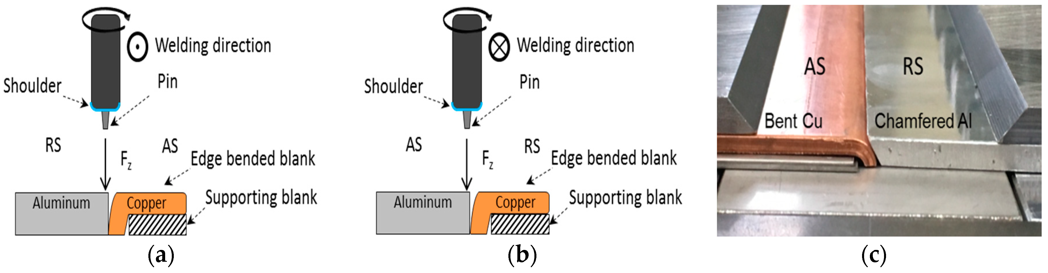
A configuration setup for the first approach is shown in Figure 1a. This first technical examination included to place the copper blank on the AS and to choose an offset towards the aluminum blank. The objective was to create sound welds following similar studies that deal with conventional friction stir butt welding of aluminum and copper. This setup contained the welding of seams 1–76. In the second approach the effect of changed plate positions was analyzed. The aluminum blanks were placed on the AS and the edge bent copper workpieces were positioned on the RS. For this approach the offset was also set in the direction of the aluminum blank. The intention of this setup was to investigate a significant material flow difference between the first and the second experimental design. Welds 77–99 were produced with this configuration setup. A schematic setup for this described approach is illustrated in Figure 1b.
The third approach of this investigation examines the effect of a chamfer on the edge of the aluminum blank. The edge bent copper was placed on the AS. Within the setup, which is shown in Figure 1c, the abutting end of the aluminum led to a slight overlap with the edge bent copper. The idea was to reduce the material deficit in the joining zone. The chamfers were manufactured manually by a belt grinder and nearly achieved 45 degrees at the edge. Furthermore, the copper and aluminum blanks were cut into shorter pieces (300 mm). This circumstance was advantageous to simplify chamfering the aluminum blanks. Friction stir welds 100–110 were produced using this approach.
The second approach did not result in any useful samples. All parametric tests, including the change of shoulder shapes, led to an insufficient compression of the weld seam and voids. The plasticized material was pressed out of the weld zone during the friction stir welding process. The weld seams of approach 2 were therefore not taken into consideration for further analyses. The used welding parameters for approaches 1 and 3 are listed in Table 2.
According to DIN EN ISO 25239-5 [23] transversal sections of the friction stir welds were detached by water jet cutting to evaluate the mechanical properties. The distance to the plunging position of the tool was 20 mm for first tensile specimen. This value deviates from the mandatory 50 mm described in DIN EN ISO 25239-5. The shape of the samples accorded with the DIN EN ISO 4136 [24] whereby the length was 190 mm. All specimens were slightly grinded on their sides with an abrasive paper to avoid the influence of notches on the detached edges during tensile testing. Other than that, no further processing of the samples was carried out. Tensile testing was conducted by a tensile test machine Zwick Z100 (Zwick GmbH & Co. KG, Ulm, Germany) at an operating speed of 10 mm/min. Furthermore, the results of tensile testing for the different approaches were compared to tensile test results of the corresponding base materials.
In addition to tensile testing metallographic analyses of the weld seams were carried out to assess the quality of the welds. Sections directly next to the extracted tensile specimens were used to prepare the metallographic samples. Metallographic samples were hot mounted with an epoxy resin. The next step contained the grinding of the metallographic specimens with SiC abrasive papers up to grain sizes of 4000 µm. In particular, the grinding was done by hand to avoid a shifting of copper particles into the aluminum side. The last step of preparing the samples included an ion-milling process.
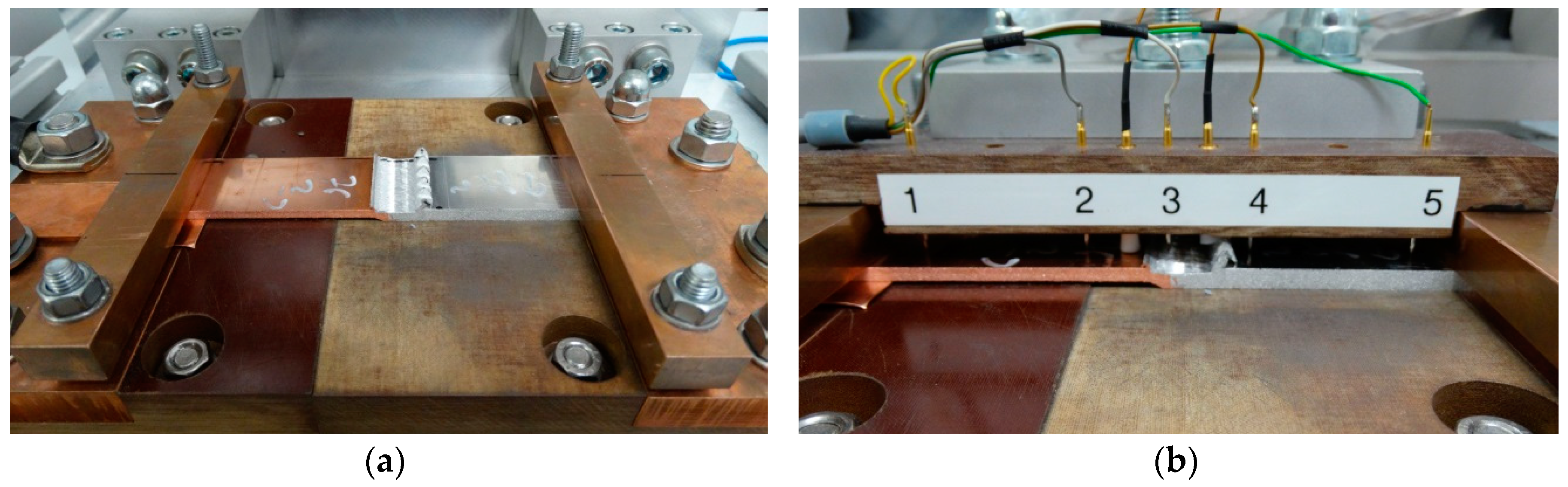
In order to examine the electrical properties of the dissimilar joints, a four point resistance measurement method was applied (Figure 2). The specimens were also detached by water jet cutting. The width of the rectangular samples was 37 mm and the length was 190 mm. During measurements the edges of the dissimilar FSW joints were contacted with a copper sheet to provide the test current of 180 A. The four measuring tips had a distance of 40 mm to each other. Via the first two tips the resistance of the copper base material was measured while tips 4 and 5 were used to determine the resistance of the aluminum base material. The friction stir welded seam was positioned between measuring tips 2 and 4. This setup allowed measuring the electrical resistances of the weld seam and of the two base materials simultaneously. The testing consisted of ten measurements for each specimen with the determined values being averaged subsequently.
The last part of this section describes the labelling of the samples. The label describes the approach type, the number of the weld, the executed testing method and the removal area. More precisely, A1.64/T/a stands for a specimen which was welded with the setup from approach 1. The investigation is related to weld seam 64 whereby a tensile test has been carried out. The last part of the sample label refers to the area where the specimens were detached, starting from position a at the beginning of the weld seam with 20 mm distance to the FSW tool plunging spot. The following detached specimens were named in an alphabetic order. For further specification Table 3 includes all the different variations.
3. Results and Discussion
3.1. Appearance of the Al–Cu Friction Stir Welds
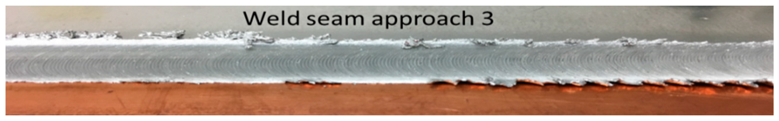
Figure 3 shows a friction stir weld produced by the use of approach 3. It was evident that only a small burr occurred on the advancing as well as on the RS. The weld seam did not show any defects at the surface.
For further investigations macrographs of approach 1 and 3 were examined. Therefore, areas of each approach were selected. Within approach 1 the specimen A1.67/M/a was analyzed. For approach 3 the samples A3.106/M/a,c were chosen. According to DIN EN ISO 25239-5 [23] a set of acceptance criteria for friction stir butt welds has to be fulfilled. The first criterion is the underfill maximum. The permissible value for blanks with a thickness of 4.7 mm is 0.67 mm. Furthermore, the permissible size of cavities was determined for each sample by the thickness of the weld seam multiplied with 0.2. The third criterion describes a complete joint penetration depth. With a lack of penetration the seam quality is invalid. Figure 4 shows the whole weld seam area of samples A1.67/M/a, A3.106/M/a, and A3.106/M/c. Figure 5 shows an enlarged area of the stir zone of specimens A1.67/M/a and A3.106/M/c.
Specimen A1.67/M/a did not fulfill the criteria of underfill maximum. A cavity was located in the middle of the stir zone. The size of this defect exceeded the acceptance criteria by almost twice the value. Because of the offset in the aluminum direction the tool pin only scratched a tiny part of the copper blank. This area can clearly be detected through the deformation at the edge bent copper. Furthermore in Figure 5 the scratched copper particles that were transported into the aluminum matrix can be seen. The diameter of these particles is between 0.15 mm and 0.24 mm. The penetration depth of this seam lacked of 0.5 mm. The macrostructure for specimen A3.106/M/a in Figure 4b shows an unsuccessful joining process. The edge bent copper blank does not show any deformation. Consequently, the pin did not scratch the copper. This is probably due to a failure in the positioning of the workpieces. The results for specimen A3.106/M/c show an underfill of 0.44 mm. This value is below the maximum permissible limit. In both cross-sectional images for sample A3.106/M/c no significant cavities are present. The observation of the joint penetration depth led to the same findings as for approach 1. The pin stirs a greater amount of large copper particles into the stir zone which was due to the lower offset. This can be seen by the severe material abrasion on the edge bent copper blank. By extension, the offset and positioning of the FSW tool created a more homogeneous stir zone compared to A1.67/M/a. Another observation of the better stirring effect can be seen in the position of the copper particles. These are spread throughout the whole stir zone. Nevertheless the FSW seam was inadequate because of the lack of penetration by 0.45 mm.
Both approaches did not fulfill the criteria from DIN EN ISO 25239-5 [23]. Approach 1 failed with respect to all three relevant criteria. The macrostructural analysis of the samples that were welded according to approach 3 showed two completely different findings. While the results for A3.106/M/c were promising, the FSW process for specimen A3.106/M/a was only performed in the aluminum base material. An irregularity in the positioning and clamping of the blanks evidently led to insufficient mixing of the materials in this area of the weld seam. In contrast, the evaluation of the macrostructure of sample A3.106/M/c led to acceptable results in case of underfill and cavities. Regardless to this fact, the lack of penetration as a criterion for exclusion led to an invalid friction stir weld quality for this approach. However, the lack of penetration can be easily addressed in further experiments by using a longer pin.
3.2. Results of Tensile Testing
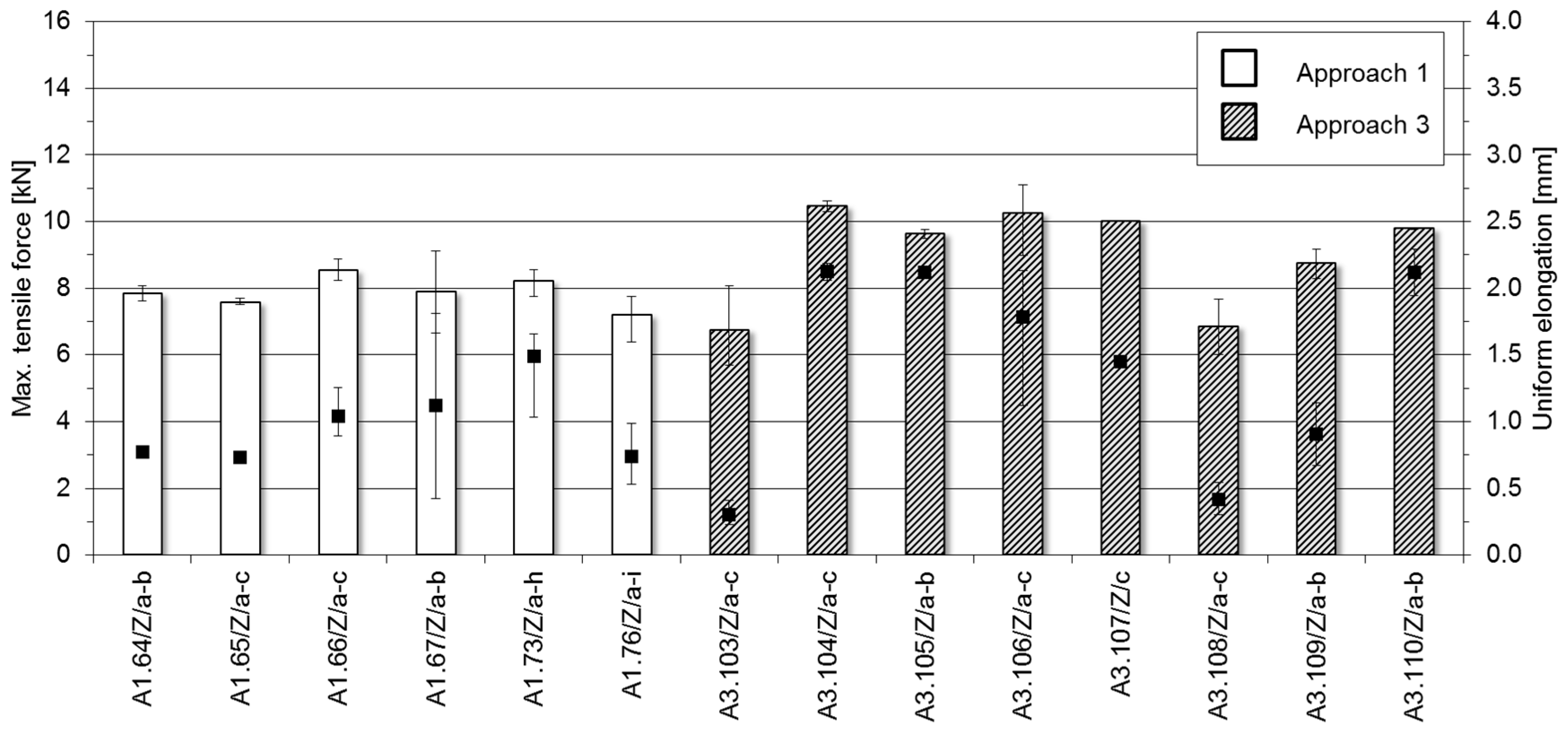
The results of the tensile tests for each weld seam are shown in Figure 6. For all welds examined in this study, failure occurred in the stir zone. Within the evaluation of the tensile tests the results were grouped into approach 1 and approach 3. In addition, Figure 6 shows mean values for each weld seam whenever more than one tensile specimen from a weld was tested. The highest average ultimate tensile force (UTF) of all friction stir welds was achieved by specimens A3.104/T/a-c with 10.45 kN. However, the lowest value was also measured for a weld that was manufactured according to approach 3. Weld seam A3.103/T/a-c obtained an average force of 6.73 kN. In general, the results for approach 1 were lower than those of approach 3. The highest overall measured tensile force was 11.09 kN. This can be seen in the range of specimen A3.106/T/a-c while sample c achieved the highest ultimate tensile force. The mean values for elongations at the maximum tensile forces are shown as black squares in the diagram. The highest values are achieved with approach 3 by specimens A3.104/T/a-c (2.12 mm) while the lowest value was as well identified for approach 3 by specimens A3.103/T/a-c (0.30 mm). The deviation is also higher for approach 3 (0.72 mm) compared to approach 1 (0.27 mm).
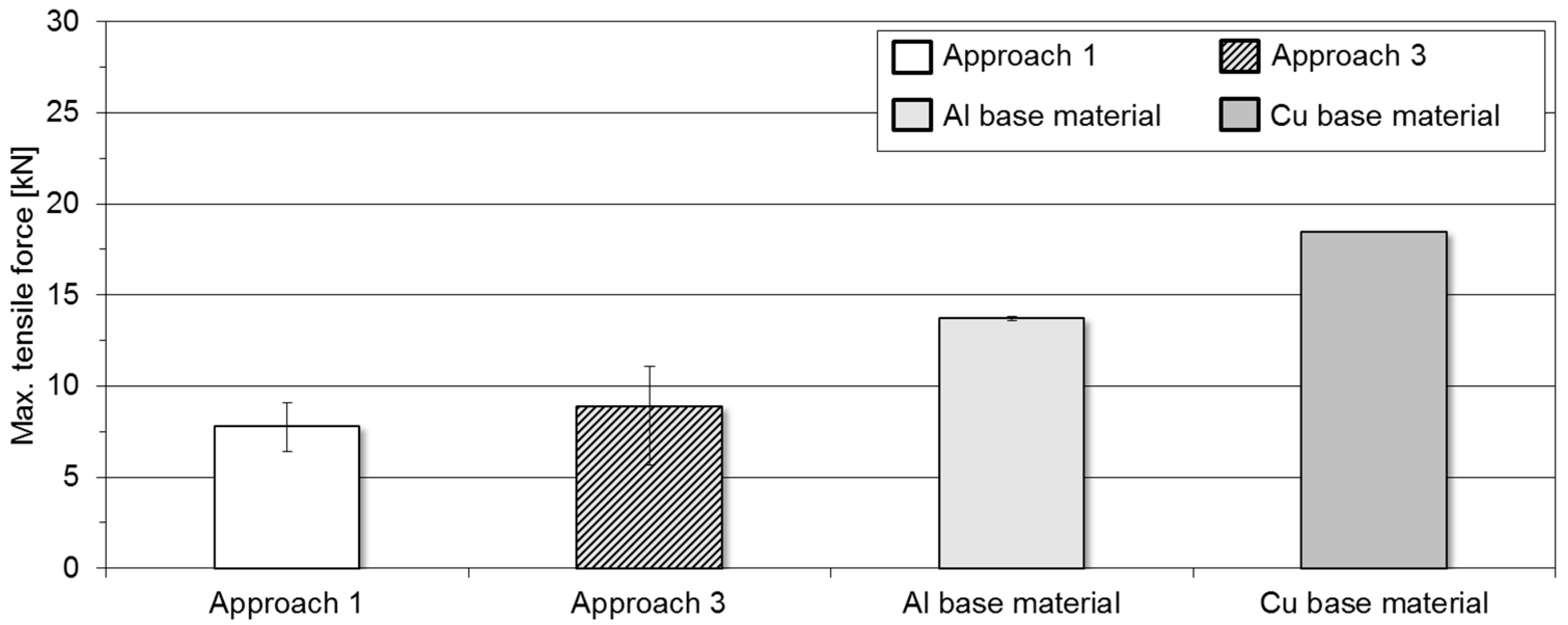
After the individual welds had been compared with each other, the tensile test results for the respective approaches 1 and 3 were summarized and compared with results for the used base materials. (Figure 7) Approach 1 reached 7.78 kN in UTF, while approach 3 led to a better result with an average UTF of 8.89 kN. Consequently, there is a difference of 1.17 kN in terms of UTF between approaches 1 and 3. However, the results of approach 1 were more consistent. The standard deviation was 0.43 kN while the outcome of approach 3 indicated a standard deviation of 1.39 kN. The aluminum base material had a mean UTF of 13.73 kN which was examined by five tensile specimens, while the UTF of the copper base material was at 18.45 kN. The average UTF of approach 1 reached approximately 57% of the aluminum base material. In contrast, approach 3 reached a joint efficiency of 65%. Within the analysis of approach 3 the highest measured UTF was at 81% of the aluminum base material for sample A3.106/T/c. The tensile test results for the two different approaches represent encouraging findings. However, especially the evaluation for approach 3 leads to the conclusion that a highly precise preparation of the chamfer, material, and tool positioning is required. These circumstances correspond to the macrostructural analysis of the welds. The highest individual UTF of all samples was achieved by specimen A3.106/T/c while the value for the first part of this weld seam (A3.106/T/a) was 24% lower due to uneven blank preparation and positioning. Excluding the two lowest values for approach 3, the UTF reached 72% compared to the aluminum base material. By using a longer tool pin resulting into a complete penetration depth, even better results can be expected in this regard.
3.3. Electrical Properties of the Friction Stir Welds
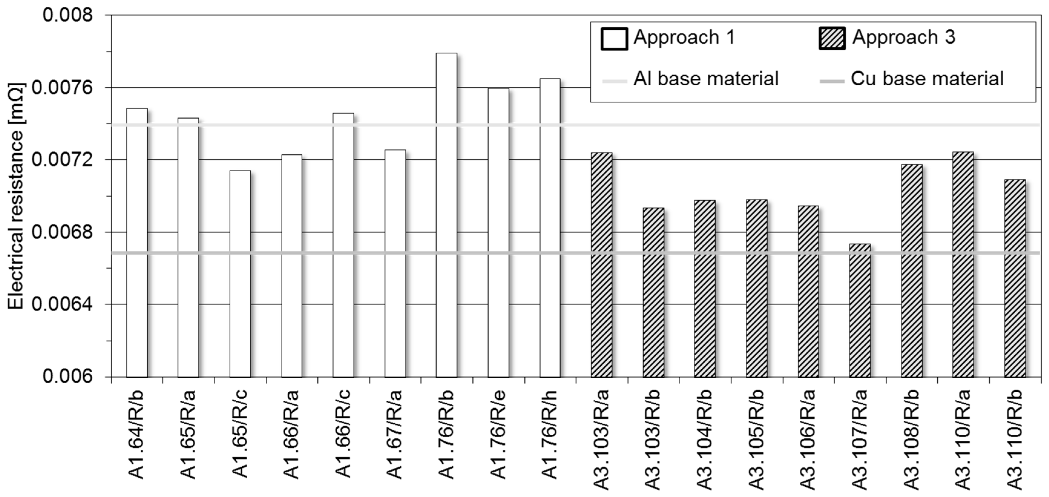
The results of the electrical resistance measurements for each sample are shown in Figure 8. The values represent the electrical resistances of the weld seams that were determined between tips 2 and 4. It is recognizable that the electrical resistances of almost all samples that were welded according to approach 1 are slightly higher than the resistances of approach 3. Exceptions are specimens A1.65/R/c, A1.66/R/a and A1.67/R/a. The range of the electrical resistances for approach 1 is approximately between 0.0071 mΩ and 0.0078 mΩ while the average value for this approach is 0.0075 mΩ. For approach 3 the values are in the range of 0.0067 mΩ and 0.0072 mΩ. The average value for all nine measurements of this approach is 0.0070 mΩ. In comparison to the determined resistances of the weld seams, the average electrical resistance of the copper material that was measured between tips 1 and 2 is 0.0067 mΩ. For the aluminum base material, an average electrical resistance of 0.0074 mΩ was measured. The aim of this study was to manufacture Al–Cu friction stir welds with a homogenous current-carrying behavior on the basis of 3 mm thick copper sheets. There is a difference in electrical resistance of 0.00071 mΩ between the respective base materials. Therefore it is evident, that the applied cross-section adjustment was not sufficient. The required cross-section adjustment was calculated following the electrical conductivities of elemental copper (58 × 106 S/m) and aluminum (37 × 106 S/m). This leads to the conclusion that the small amount of alloying additions in the high purity materials used influences the electrical properties in a way that the realized cross-section adjustment was not precise enough. In order to obtain similar electrical conductivities between the respective base materials an adjustment factor of 1.73 is required for the present material combination. However, especially the results for approach 3 can be considered as very positive. These results deviate only slightly from the results of the copper base material. This deviation is suspected not to be only due to the insufficient cross-section adjustment, but also because of the underfill which is a result of the shoulder penetration. The underfill reduces the current-carrying cross-section which leads to an increase of the electrical resistance. Taking this into account, for a homogenous current-carrying behavior aluminum sheets with thicknesses of at least 5.2 mm are needed when the task is to manufacture cross-section-adjusted Al–Cu butt joints on the basis of 3 mm thick copper sheets.
Besides analyzing the measured electrical resistances, the electrical properties of the friction stir welds can be assessed by calculating the resistance factor ku for each specimen. The resistance factor permits a material- and process-independent evaluation of the electrical joint properties. The dimensionless resistance factor ku is calculated by doubling the electrical resistance of the weld seam and dividing the summed resistances of the respective base materials [25]:
The resistance factors in Figure 9 were calculated using the electrical resistances of the weld seams and the respective base materials from Figure 8. Ideally, the resistance factor of butt joints can reach the minimum value 1. If the resistance factor ku is lower than 1.5, the joint accomplishes the criteria of long-term stability [26]. This criterion is met for all examined specimens. Therefore, a long-term stable electrical behavior can be expected for both approaches 1 and 3. The highest calculated resistance factor was 1.11 for specimen A1.76/R/b while the lowest value was calculated for specimen A3.107/R/a. The resistance factor for this sample (0.97) and five more samples that were welded according to approach 3 are even below the ideal limit. This indicates a higher amount of copper in the measured area between tips 2 and 4.
4. Conclusions
In this study, the mechanical and electrical properties of cross-section-adjusted friction stir butt welds were investigated. The applied materials were copper EN CW008A with a thickness of 3 mm and aluminum EN AW-1050A with a thickness of 4.7 mm. Therefore, three different approaches were tested with the aim to produce sound welds with properties similar to those of the used base materials.
- Approach 1 included copper blanks that were edge bent on one side. These were positioned on the AS. The welds were produced with a welding speed of 450 mm/min.
- Approach 2 included copper blanks that were edge bent on one side. These were positioned on the RS. Using this approach no sound welds could be achieved. This is the reason why samples that were welded according to this approach were ignored for further analysis.
- Approach 3 included copper blanks that were edge bent on one side. These were positioned on the AS. Within this approach, the aluminum blanks were chamfered on one side to reduce the material deficit in the joining area. The welds were produced with a welding speed of 450 mm/min.
- The results of the macrostructural analysis showed a lack of penetration for both approaches and inadmissible cavities for approach 1. In general, the underfill maximum was smaller for approach 3.
- The average UTF for samples that were welded according to approach 1 was 7.78 kN while approach 3 achieved an average value of 8.89 kN. Compared to the aluminum base material, the joint efficiency was 57% for approach 1 and 65% for approach 3, respectively. The specimen with the best mechanical properties had a joint efficiency of 81%.
- The average electrical resistance for approach 1 was 0.0075 mΩ and for approach 3 the electrical resistance was 0.0070 mΩ. The calculated resistance factor for both approaches indicated a long-term stable behavior of the joints.
- In general, welds with good tensile properties lead to lower electrical resistances.
Especially by approach 3, promising results could be achieved. Considering the quality criteria from DIN EN ISO 25239-5, the lack of penetration has to be avoided. Therefore, in further experiments a longer tool pin will be used. The chamfer on the aluminum blank led to better mechanical and electrical joint properties due to the reduced material deficit in the joining area. However, exact positioning of the blanks was complicated by the chamfer with the result of a few welds showing insufficient scratching of the copper base material. Further investigations with standardized chamfer geometries and seam tracking could even improve the results.
Author Contributions
Conceptualization, N.E., A.H., and A.F.; Formal analysis, N.E. and A.H.; Investigation, N.E. and J.D.; Methodology, N.E.; Project administration, A.H. and A.F.; Supervision, A.F. and S.B.; Visualization, J.D.; Writing–original draft, N.E.; Writing–review and editing, A.H. and S.B.
Funding
This research was funded by Volkswagen AG corporate research.
Conflicts of Interest
The authors declare no conflict of interest.
References
- Li, X.-W.; Zhang, D.-T.; Qiu, C.; Zhang, W. Microstructure and mechanical properties of dissimilar pure copper/1350 aluminum alloy butt joints by friction stir welding. Trans. Nonferrous Met. Soc. China 2012, 22, 1298–1306. [Google Scholar] [CrossRef]
- Deutsches Kupfer-Institut e.V. Kupfer in der Elektrotechnik—Kabel und Leitungen; Deutsches Kupfer-Institut: Düsseldorf, Germany, 2000. [Google Scholar]
- Bargel, H.-J.; Schulze, G. Werkstoffkunde; Springer: Düsseldorf, Germany, 2016. [Google Scholar]
- Braunovic, M.; Myshkin, N.K.; Konchits, V.V. Electrical Contacts: Fundamentals, Applications and Technology. Taylor and Francis Distributor; CRC Press: Boca Raton, FL, USA, 2007. [Google Scholar]
- Khodir, S.A.; Ahmed, M.M.Z.; Ahmed, E.; Mohamed, S.M.R.; Abdel-Aleem, H. Effect of Intermetallic Compound Phases on the Mechanical Properties of the Dissimilar Al/Cu Friction Stir Welded Joints. J. Mater. Eng. Perform. 2016, 25, 4637–4648. [Google Scholar] [CrossRef]
- Xue, P.; Xiao, B.L.; Ni, D.R.; Ma, Z.Y. Enhanced mechanical properties of friction stir welded dissimilar Al–Cu joint by intermetallic compounds. Mater. Sci. Eng. A 2010, 527, 5723–5727. [Google Scholar] [CrossRef]
- Xue, P.; Ni, D.R.; Wang, D.; Xiao, B.L.; Ma, Z.Y. Effect of friction stir welding parameters on the microstructure and mechanical properties of the dissimilar Al–Cu joints. Mater. Sci. Eng. A 2011, 528, 4683–4689. [Google Scholar] [CrossRef]
- Barekatain, H.; Kazeminezhad, M.; Kokabi, A.H. Microstructure and Mechanical Properties in Dissimilar Butt Friction Stir Welding of Severely Plastic Deformed Aluminum AA 1050 and Commercially Pure Copper Sheets. J. Mater. Sci. Technol. 2014, 30, 826–834. [Google Scholar] [CrossRef]
- Zhang, Q.-Z.; Gong, W.-B.; Liu, W. Microstructure and mechanical properties of dissimilar Al–Cu joints by friction stir welding. Trans. Nonferrous Met. Soc. China 2015, 25, 1779–1786. [Google Scholar] [CrossRef]
- Al-Roubaiy, A.O.; Nabat, S.M.; Batako, A.D.L. Experimental and theoretical analysis of friction stir welding of Al–Cu joints. Int. J. Adv. Manuf. Tech. 2014, 71, 1631–1642. [Google Scholar] [CrossRef]
- Thomas, W.M.; Nicholas, E.D.; Needham, J.C.; Murch, M.G.; Templesmith, P.; Dawes, C.J. Improvements Relating to Friction Welding. U.S. Patent 5,460,317, 10 June 1993. [Google Scholar]
- Matthes, K.-J.; Schneider, W. Schweißtechnik. Schweißen von Metallischen Konstruktionswerkstoffen; Carl Hanser Verlag: München, Germany, 2016. [Google Scholar]
- Celik, S.; Cakir, R. Effect of Friction Stir Welding Parameters on the Mechanical and Microstructure Properties of the Al-Cu Butt Joint. Metals 2016, 6, 133. [Google Scholar] [CrossRef]
- Mishra, R.S.; De, P.S.; Kumar, N. Friction Stir Welding and Processing: Science and Engineering; Springer International Publishing: New York, NY, USA, 2014. [Google Scholar]
- Ott, M. Neues Verfahren fügt Bleche besser zusammen. Aluminium Praxis, 3 February 2017. [Google Scholar]
- Fratini, L.; Buffa, G.; Shivpuri, R. Improving friction stir welding of blanks of different thicknesses. Mater. Sci. Eng. A 2007, 459, 209–215. [Google Scholar] [CrossRef]
- Sahu, P.K.; Pal, S. Mechanical properties of dissimilar thickness aluminium alloy weld by single/double pass FSW. J. Mater. Process. Technol. 2017, 243, 442–455. [Google Scholar] [CrossRef]
- Ezumi, M. Friction Stir Welding Method of Two Members Having Different Thicknesses. Google Patent EP1825946A1, 29 August 2007. [Google Scholar]
- Weigl, M.; Feineis, A.; Sascha, C.; Kunz, M. Verfahren und Vorrichtung zum Rührreibschweißen bei Materialien unterschiedlicher Dicke und bei Kehlnähten. Google Patent DE102014001050A1, 30 July 2015. [Google Scholar]
- Werz, M.; Hoßfeld, M.; Volz, O. Verfahren zum Stumpfverschweißen sowie Bauteil und Rührreibschweißwerkzeug. Google Patent DE102013110034A1, 12 March 2015. [Google Scholar]
- Deutsches Institut für Normung e.V. Aluminium und Aluminiumlegierungen—Chemische Zusammensetzung und Form von Halbzeug—Teil 3: Chemische Zusammensetzung und Erzeugnisformen; Beuth Verlag GmbH: Berlin, Germany, 2013; DIN EN 573-3. [Google Scholar]
- Deutsches Institut für Normung e.V. Kupfer und Kupferlegierungen—Platten, Bleche und Bänder aus Kupfer für die Anwendung in der Elektrotechnik; Beuth Verlag GmbH: Berlin, Germany, 2014; DIN EN 13599. [Google Scholar]
- Deutsches Institut für Normung e.V. Rührreibschweißen—Aluminium—Teil 5: Qualitäts-und Prüfungsanforderungen; Beuth Verlag GmbH: Berlin, Germany, 2012; DIN EN ISO 25239-5. [Google Scholar]
- Deutsches Institut für Normung e.V. Zerstörende Prüfung von Schweißverbindungen an Metallischen Werkstoffen—Querzugversuch; Beuth Verlag GmbH: Berlin, Germany, 2013; DIN EN ISO 4136:2012. [Google Scholar]
- Schmidt, P.A. Laserstrahlschweissen Elektrischer Kontakte von Lithium-Ionen-Batterien in Elektro- und Hybridfahrzeugen; Herbert Utz: München, Germany, 2015. [Google Scholar]
- Essers, M.; Schiebahn, A.; Reisgen, U. Widerstandsbuckelschweißen von Al-Cu-Mischverbindungen zur Generierung elektrischer Kontaktierungen. Große Schweißtechnische Tagung, DVS-Studentenkongress, Nürnberg, Germany, 17 September 2015. [Google Scholar]
Figure 1.
(a) Friction stir welding (FSW) setup with Cu on advancing side (AS); (b) Setup with Al on AS; and (c) setup with chamfer on Al edge.
Figure 1.
(a) Friction stir welding (FSW) setup with Cu on advancing side (AS); (b) Setup with Al on AS; and (c) setup with chamfer on Al edge.

Figure 2.
(a) Test specimen installed on measuring system. (b) Test setup with measuring tips.

Figure 3.
Surface morphology of Al–Cu friction stir weld seam using approach 3.

Figure 4.
Cross-sectional macrostructures of Al–Cu friction stir welds: (a) specimen A1.67/M/a; (b) specimen A3.106/M/a; and (c) specimen A3.106/M/c.
Figure 4.
Cross-sectional macrostructures of Al–Cu friction stir welds: (a) specimen A1.67/M/a; (b) specimen A3.106/M/a; and (c) specimen A3.106/M/c.
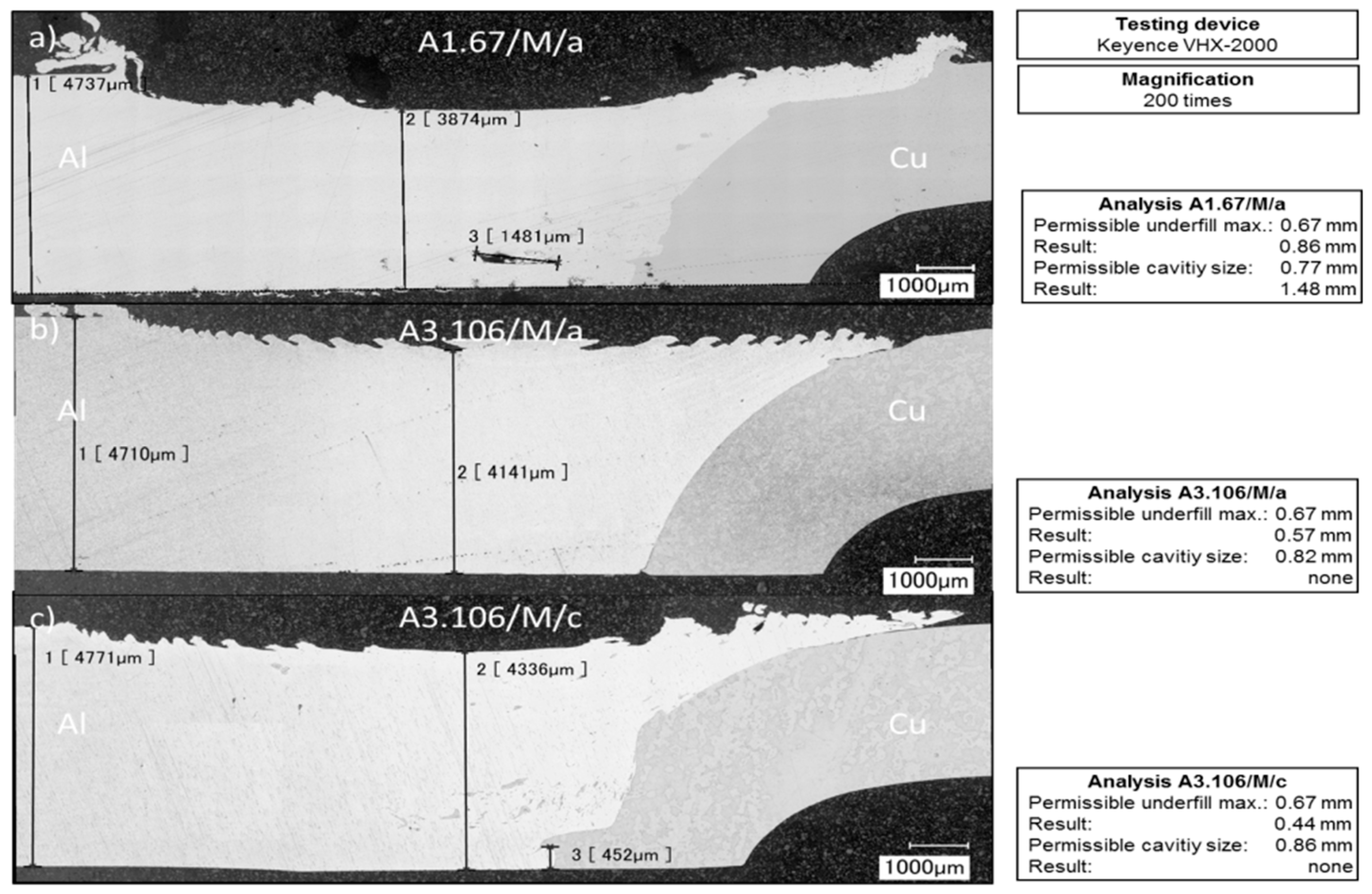
Figure 5.
Magnified view on the macrostructures of Al–Cu friction stir welds: (a) specimen A1.67/M/a and (b) specimen A3.106/M/c.
Figure 5.
Magnified view on the macrostructures of Al–Cu friction stir welds: (a) specimen A1.67/M/a and (b) specimen A3.106/M/c.

Figure 6.
Ultimate tensile forces and elongations for specimens that were welded according to approach 1 and approach 3.
Figure 6.
Ultimate tensile forces and elongations for specimens that were welded according to approach 1 and approach 3.

Figure 7.
Averaged ultimate tensile forces for approach 1, approach 3, aluminum, and copper base material.
Figure 7.
Averaged ultimate tensile forces for approach 1, approach 3, aluminum, and copper base material.

Figure 8.
Electrical resistance measurement for approach 1 and approach 3.

Figure 9.
Resistance factors of the examined Al–Cu friction stir welds.


| Materials | Al | Fe | Si | Mn | Mg | Zn | Ti | Pb | Bi | Cu |
|---|---|---|---|---|---|---|---|---|---|---|
| EN AW-1050A | ≥99.50 | ≤0.40 | ≤0.25 | ≤0.05 | ≤0.05 | ≤0.07 | ≤0.05 | - | - | ≤0.05 |
| CW008A | - | - | - | - | - | - | - | ≤0.005 | ≤0.0005 | ≥99.95 |
Table 2.
Used welding parameters for approaches 1 and 3.
| Approach | Rotational Speed (rpm) | Feed Rate (mm/min) | Plunge Depth (mm) | Dwell Time (s) | Tool Tilt Angle(°) | Tool Pin Length (mm) | Tool Shoulder Shape | Offset(mm) |
|---|---|---|---|---|---|---|---|---|
| A1 | 1100 | 450 | 4.25 | 2 | 4 | 3.7 | flat | 2.0 |
| A3 | 1100 | 450 | 4.20 | 2 | 3 | 3.8 | flat | 1.8 |
Table 3.
Tabular list of specimen labeling.
| Approach | FSW No. | Method | Order |
|---|---|---|---|
| A1 | 1–76 | T = Tensile testing | a–i |
| A3 | 100–110 | M = Metallographic analysis | a–c |
| - | - | R = Electrical resistance | - |
© 2018 by the authors. Licensee MDPI, Basel, Switzerland. This article is an open access article distributed under the terms and conditions of the Creative Commons Attribution (CC BY) license (http://creativecommons.org/licenses/by/4.0/).
Share and Cite
MDPI and ACS Style
Eslami, N.; Harms, A.; Deringer, J.; Fricke, A.; Böhm, S. Dissimilar Friction Stir Butt Welding of Aluminum and Copper with Cross-Section Adjustment for Current-Carrying Components. Metals 2018, 8, 661. https://doi.org/10.3390/met8090661
AMA Style
Eslami N, Harms A, Deringer J, Fricke A, Böhm S. Dissimilar Friction Stir Butt Welding of Aluminum and Copper with Cross-Section Adjustment for Current-Carrying Components. Metals. 2018; 8(9):661. https://doi.org/10.3390/met8090661
Chicago/Turabian StyleEslami, Nima, Alexander Harms, Johann Deringer, Andreas Fricke, and Stefan Böhm. 2018. "Dissimilar Friction Stir Butt Welding of Aluminum and Copper with Cross-Section Adjustment for Current-Carrying Components" Metals 8, no. 9: 661. https://doi.org/10.3390/met8090661
Note that from the first issue of 2016, this journal uses article numbers instead of page numbers. See further details here.