New Technology to Produce 1 GPa Low Carbon Microalloyed Steels from Cast Strip

School of Mechanical, Materials, Mechatronic and Biomedical Engineering, University of Wollongong, NSW 2500, Australia
*
Author to whom correspondence should be addressed.
Metals 2018, 8(9), 662; https://doi.org/10.3390/met8090662
Submission received: 4 August 2018
/
Revised: 18 August 2018
/
Accepted: 22 August 2018
/
Published: 24 August 2018
(This article belongs to the Special Issue Development of Bainitic Steels)
Abstract
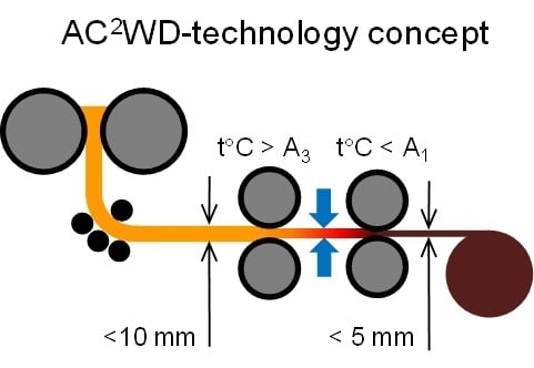
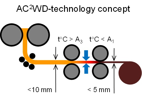
:Global economy requires steel with further increasing mechanical properties and simultaneously decreasing price. In mass manufacturing three major methods can be used to increase strength: (i) increase microalloying element additions (increases cost), (ii) decrease deformation temperature and (iii) increase cooling rate after high temperature processing (both can be challenging for equipment). Thin strip casting is an effective way to reduce cost as it brings a reduction in number of deformation passes and shortens the production line. However, the mechanical properties can be missed due to insufficient microstructure development. In this article, we investigate a recently proposed technology based on Austenite Conditioning followed by Accelerated Cooling and Warm Deformation (AC2WD). Two low carbon steels microalloyed with either 0.012Ti or 0.1Mo-0.064Nb-0.021Ti (wt.%) were subjected to three processing modifications of the AC2WD-technology with two, one or no deformation of cast microstructure in the austenite temperature field. The Ti- and MoNbTi-steels exhibited 685–765 MPa and 880–950 MPa of the yield stress, 780–840 MPa and 1035–1120 MPa of tensile strength, and 20–30% and 22–24% of elongation to failure, respectively. The nature of strengthening mechanisms associated with the AC2WD-technology is discussed on the basis of detailed microstructure characterisation.
1. Introduction
Iron and steel industries are responsible for ~5% of the global energy consumption and ~7% of total CO2 emissions [1]. Energy constitutes from 20 to 40% of steel production cost [2]. Therefore, reductions in energy consumption are undoubtedly beneficial from both social and economic points of view. Technology developments of recent decades, such as utilisation of scrap, continuous casting, collection of by-product gases, allowed substantial reductions in energy usage (up to 60% since 1960s). In the area of flat product manufacturing, Compact Strip Production (CSP) (thin slab casting followed by five or six rolling passes) and Strip Casting (thin strip casting followed by one rolling pass) became breakthrough technologies bringing about two and nine times reduction in energy consumption, respectively [3]. The CSP technology is used to manufacture carbon, high strength low alloyed, stainless, silicon rich, quenched and tempered, and dual phase ultra-high strength steels [4,5,6,7,8,9]. The Strip Casting technology allows to manufacture carbon, silicon rich, stainless and microalloyed steels [10,11,12,13]. In recent laboratory investigations, dual phase [14] and transformation-induced plasticity [15] steels have been successfully obtained by strip casting. In spite of these noticeable achievements, attaining the desired microstructure-properties relationship remains a challenge for thin cast products. For example, our recent studies of dual phase strip cast steels showed a decrease in total elongation with an increase in strength [14]. A decrease in temperature of single deformation cycle did improve ductility via ferrite grain refinement [16]. However, the strength decreased with a decrease in deformation temperature. This could be explained if a decrease in deformation temperature resulted in an increase in start temperature of austenite to ferrite transformation, A3, (reduced hardenability) leading to the decreased dislocation density in ferrite. An increase in A3 temperature with austenite deformation was observed previously in low and medium carbon steels [17,18,19]. On a whole, reduced hot deformation strain results in sluggish recrystallisation, large prior austenite grain size, large grain size of low temperature phases (ferrite, bainite, martensite), and reduced ductility. In steels microalloyed with strong carbonitride forming elements, low strains may lead to insufficient precipitation strengthening, if strain induced precipitation did not take place. Therefore, investigation of the effect of hot deformation on ambient temperature microstructure and properties plays an important role in the development of future steel processing technologies. An increasing demand for steel, due to the growing human population, will bring another constraint to new technologies and products—low cost. In addition to the reduced amount of hot deformation, decreased contents of expensive microalloying elements would also contribute to the cost decrease. Thus, it would be beneficial if the new steel processing technology assured the best combination of properties not only with minimum deformation cycles but also utilising the simplest steel composition.
2. Technology Development
Grain refinement is known to be the only microstructure development mechanism increasing strength and ductility simultaneously. Therefore, many technologies have been developed to reduce grain size [20]. These technologies are mainly based on either “severe plastic deformation” or “advanced thermomechanical processing”. Severe plastic deformation is difficult to achieve in high volume manufacturing (plate and strip rolling). Thus, in this case, development of thermomechanical processing should be undertaken. To reduce ferrite grain size, one or more of the following mechanisms can be utilised in the process design: dynamic recrystallization of austenite followed by transformation to ferrite [21,22,23,24]; strain induced ferrite transformation [16,25,26,27,28]; hot deformation in the austenite/ferrite two-phase region [29]; warm deformation in the ferrite region [30,31,32]; accelerated cooling [23,33]; or cold rolling and annealing of a martensitic microstructure [34,35,36]. However, the effect of grain size on tensile elongation and ductility may impose a restriction on application of the grain refinement mechanism: tensile elongation significantly decreases below 10% with a decrease in grain size below 1 m [31,37]. Therefore, optimum grain size should, probably, be at the level of 1.5–2 m. According to the Hall-Petch relationship, this would contribute up to 600 MPa to the yield stress. Further strengthening must come from solid solute atoms (and their clusters), particle precipitation, and substructure (dislocation density, shear bands). Atom and particle strengthening rely on the cost of steel composition. The substructure can be modified with processing if appropriate equipment is available. In view of these considerations, we suggested the AC2WD technology [38], which stands for austenite conditioning (AC) followed by accelerated cooling (AC) and warm deformation (WD). Austenite conditioning is supposed to prepare austenite for transformation, via development of a certain prior austenite grain size and substructure. Accelerated cooling helps to reduce grain size of low temperature phases and increase dislocation density. Warm deformation further improves the substructure via work hardening. If a steel is microalloyed, holding after the deformation allows to control atom partitioning between the matrix and precipitates and to achieve the maximum strengthening contribution from solute atoms and precipitates. One of the key questions about the new technology is “what kind of austenite conditioning is required?” or in other words, “do we need hot deformation?” An attempt to answer this question is presented below.
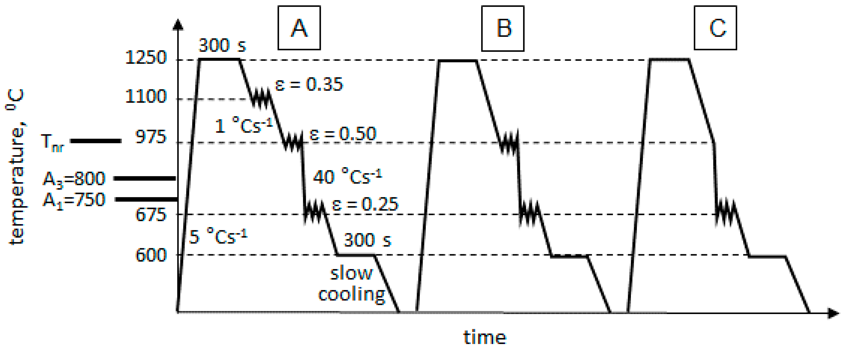
Figure 1 shows the three thermomechanical processing schedules investigated here. The route A included: austenitising at 1250 °C for 300 s, cooling to 1100 °C at 1 °C s−1, first deformation at 1100 °C to 0.35 strain at 5 s−1 strain rate, cooling to 975 °C at 1 °C s−1, second deformation at 975 °C to 0.50 strain at 5 s−1 strain rate, cooling to 675 °C (this temperature was chosen to be below A1 ≈ 750 °C for the studied steels, see “Materials and Methods” section below) at a cooling rate of 40 °C s−1 (this cooling rate had to assure retention of deformed microstructure after the second deformation, prevention of pearlite formation and facilitation of bainite formation), third deformation at 675 °C to 0.25 strain at 5 s−1 strain rate (to give sufficient work hardening), holding at 600 °C for 300 s (to finish bainite transformation, allow for some recovery to take place and promote particle precipitation). From route A, route B differed in the absence of deformation at 1100 °C, and route C differed in the absence of both deformations at 1100 °C and 975 °C. Such processing schedules were designed to provide dynamic recrystallization (DRX) of austenite and retention of substructure in austenite (route A), absence of DRX but retention of austenite substructure (route B), and retention of cast microstructure due to absence of any austenite deformation (route C).
3. Effect of Processing on Microstructure
The three processing technologies presented in Figure 1 have been tested on two microalloyed steels with varying contents of Ti, Nb and Mo: 0.095C-0.012Ti (wt.%) designated as Ti-steel and 0.081C-0.1Mo-0.064Nb-0.021Ti (wt.%) designated as MoNbTi-steel. These two steels have been chosen to investigate additions of Mo and Nb on microstructure and mechanical properties. Both of these elements were expected to facilitate bainite transformation [39,40,41,42,43,44,45,46,47] during accelerated cooling prior to warm deformation.
3.1. Grain Structure and Phase Balance
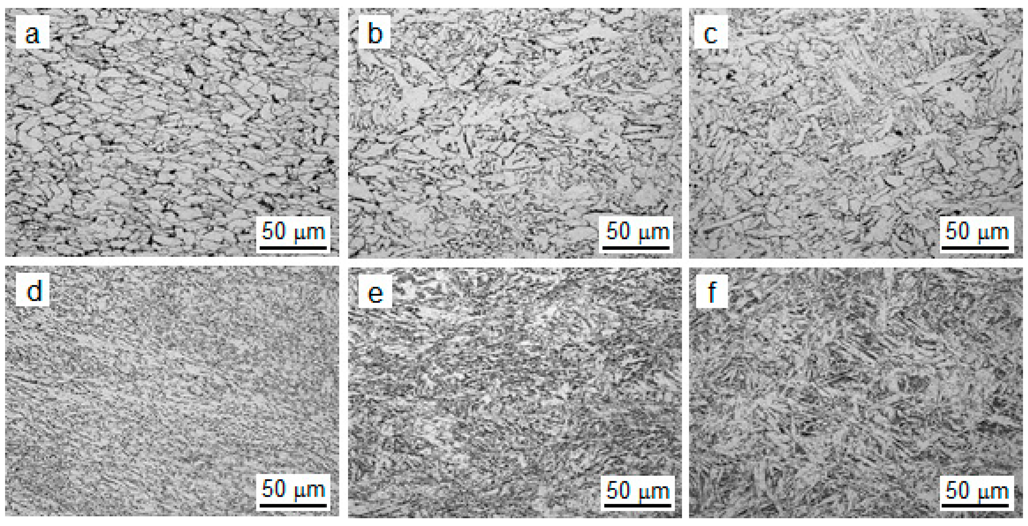
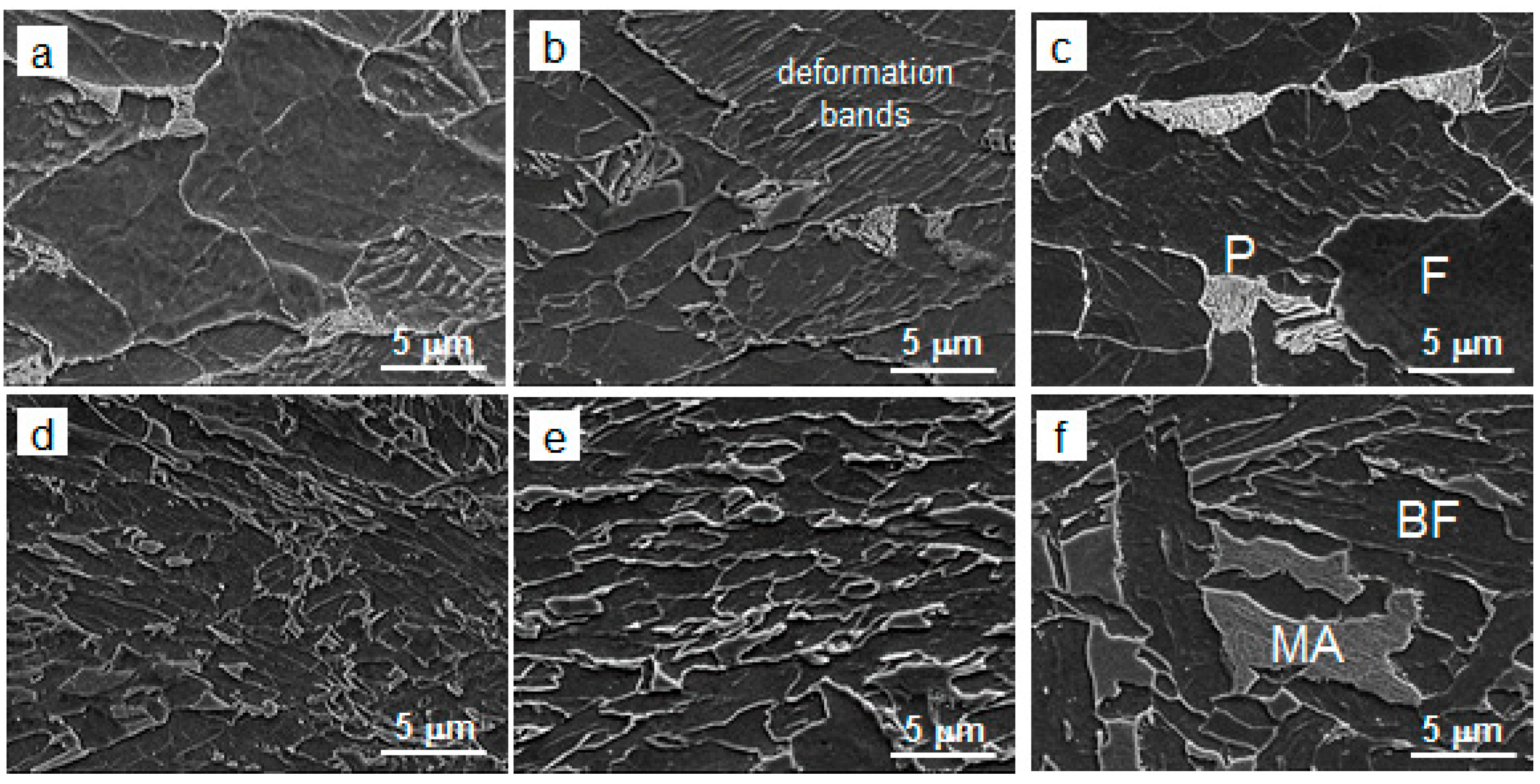
The additions of Mo and Nb did affect the microstructure phase balance and particle precipitation. The microstructure consisted of ferrite and pearlite in the Ti-steel (Figure 2a–c) and of granular bainite in the MoNbTi-steel (Figure 2d–f). The average ferrite grain size in the Ti-steel was several times larger than the average width of bainitic ferrite areas in the MoNbTi-steel (Table 1). Elimination of hot deformation facilitated austenite transformation to a more acicular microstructure in both steels. In particular, the ferrite grain size in Ti-steel and bainitic ferrite area width in the MoNbTi-steel decreased by 2–2.5 times from route A to C (Table 1). In the Ti-steel, the deformation bands have been observed in almost all ferritic grains (Figure 3a–c), although a limited number of bainitic ferrite areas in the MoNbTi-steel contained the deformation bands (Figure 3d–f). In the Ti-steel, the majority of deformation bands were running at a distance of 200–600 nm from each other. A processing route variation did not affect the distribution of deformation bands. Obviously, they appeared as a result of a warm deformation cycle, which was similar for the three studied processing routes. The second phase was pearlite in the Ti-steel and martensite-austenite (MA) constituent in the MoNbV-steel. The average size of second phase grains was larger in the Ti-steel. However, the difference in average size of second phase grains decreased with elimination of hot deformation from 2.7 times for route A to 1.5 times for route B and to 5% for route C. The second phase fraction was 2–3 times larger in the MoNbTi-steel compared to the Ti-steel. The second phase fraction increased with elimination of hot deformation (from route A to B to C) in both steels, and was increasing faster in the MoNbTi-steel. These variations in ambient temperature grain structure could originate from two major mechanisms: (i) dynamic recrystallization (DRX) of austenite, leading to development of prior austenite grains of certain size; and (ii) kinetics of austenite transformation during cooling, determining types and parameters of low temperature phases.
Figure 4 and Figure 5 illustrate our understanding of the grain structure variation with austenite conditioning and steel composition observed here.
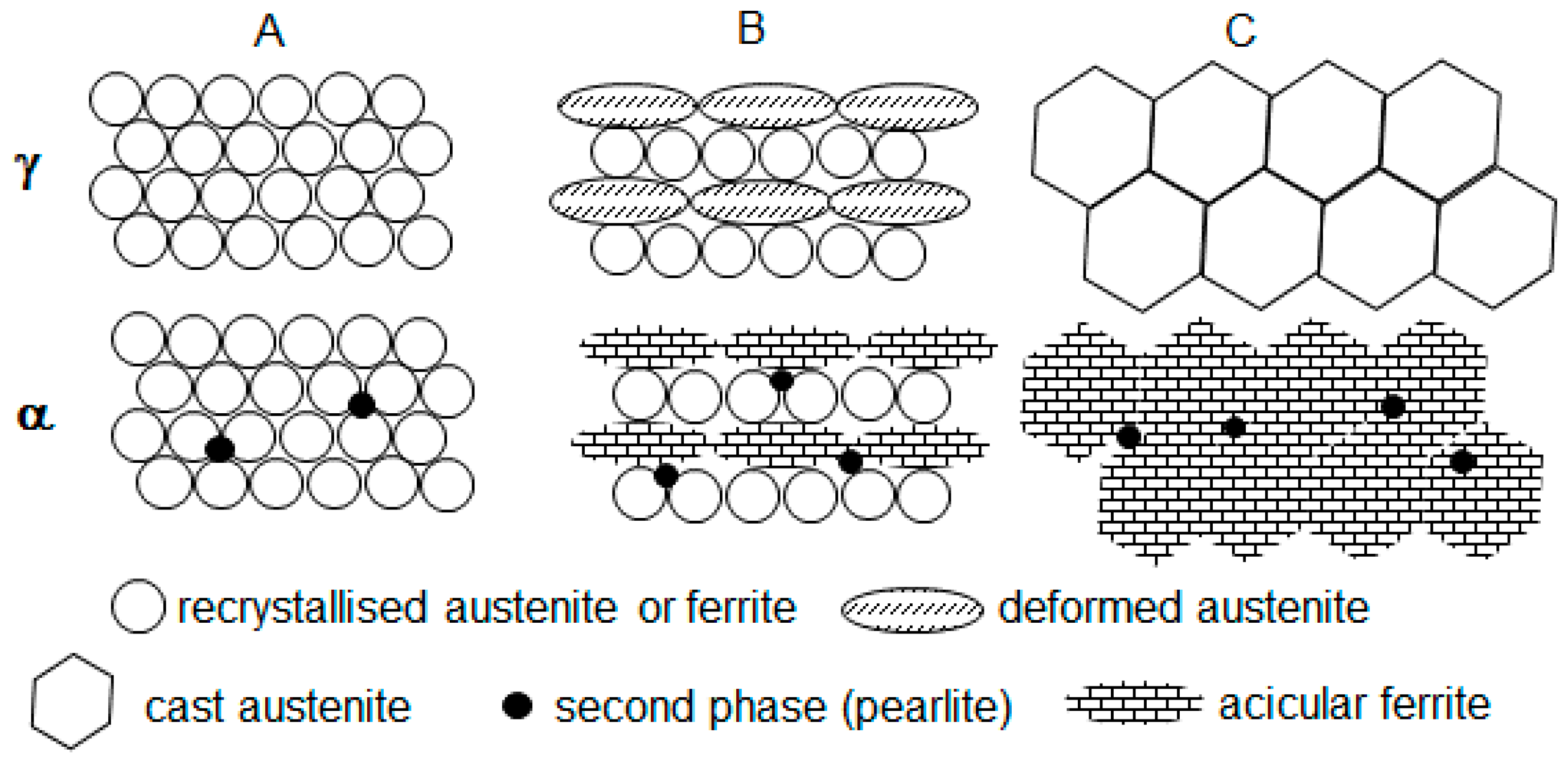
In the Ti-steel (Figure 4):
- Two high temperature deformations (route A) resulted in pronounced DRX and fine-grained austenite; during cooling the fine-grained austenite transformed to fine-grained ferrite (a substantial number of ferrite nucleation sites was determined by the large length of prior austenite grain boundaries); a significantly lower second phase fraction (2.5% in contrast to 10.9%, expected for 0.095 wt.% C on the basis of lever rule) formed as a result of accelerated cooling (40 C s−1); the ferrite solution was supersaturated with Carbon;
- One high temperature deformation (route B) resulted in partial DRX and formation of two types of austenite grains, fine recrystallised and large deformed non-recrystallised; during cooling the large deformed grains transformed to rather acicular ferrite grains (an increase in acicular ferrite fraction with an increase in austenite grain size was reported previously [48]) and fine recrystallised grains transformed to rather polygonal ferrite grains—this decreased the average measured value of ferrite grain size from 10 m for route A to 4.8 m for route B (Table 1); a slightly higher pearlite fraction, 3.2% for route B compared to 2.5% for route A, might be associated with slower strain induced precipitation of carbides and more Carbon available in solid solution for the pearlite reaction;
- Without high temperature deformation (route C), the large cast grains transformed to acicular ferrite (in addition to the effect of grain size, the austenite to ferrite transformation start temperature A3 could decrease with elimination of deformation [49,50], this would also facilitate the transformation to acicular ferrite instead of polygonal), although some polygonal ferrite formation could take place on austenite grain boundaries; a further minor increase in the pearlite fraction, from 3.2% for route B to 4.3% for route C, might be associated with an increase in remaining austenite fraction at the end of cooling, this austenite fraction would transform to pearlite during holding after the deformation (deformation was reported to facilitate the pearlite reaction [51]).
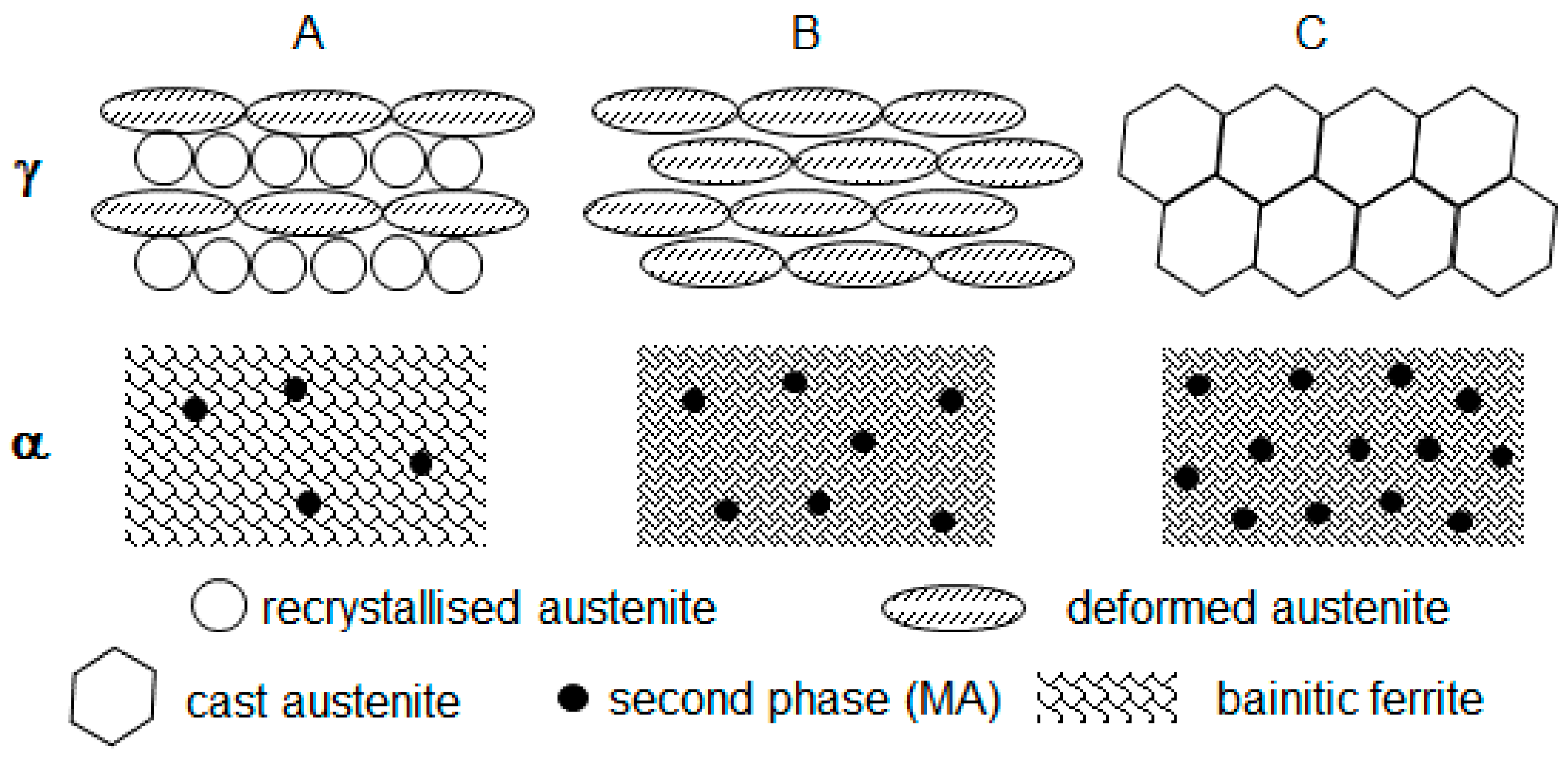
In the MoNbTi-steel (Figure 5):
- In spite of two high temperature deformations (route A) DRX was, probably, partial; this would correspond to a higher recrystallization stop temperature of the MoNbTi-steel (975 °C) than this of the Ti-steel (900 °C) [52]; during cooling the austenite grains of all types were transforming to bainitic ferrite, as a result of Mo [39,40,41,42] and Nb [43,44,45,46,47] promoting the bainite transformation; the second phase MA constituent formed from the austenite retained after bainitic ferrite transformation; transformation to MA occurred during the final cooling to ambient temperature after the warm deformation cycle;
- One high temperature deformation (route B) did not create conditions for DRX (the deformation temperature of 975 °C was equal to Tnr); therefore, large deformed non-recrystallised grains dominated; during cooling, the dislocation structure retained in austenite facilitated transformation to a finer bainitic ferrite (1 m of bainitic ferrite area width for route B in contrast to 2.5 m for route A, Table 1) via an increased nucleation rate (pre-deformation was observed increasing the bainite transformation rate [53]); however, the rate of bainitic ferrite growth might be reduced because of retained dislocation structure (stronger austenite slower transforms to bainite [54]); this resulted in an increased volume fraction of the second phase MA, 7.7% for route B compared to 5.5% for route A (the bainite volume fraction was observed decreasing with strain [55]);
- Without high temperature deformation (route C) large cast grains sustained, although their size could be smaller in the MoNbV-steel than in the Ti-steel due to the retardation of grain growth by Mo [56,57] and Nb [58,59,60] solute atoms and precipitates; during cooling large non-deformed austenitic grains could faster transform to bainite, due to the austenite being softer, and the bainite transformation could start at a higher temperature [61]—this would favour an increase in the bainite volume fraction; however, the potential number of nucleation sites was lower, and thus, a decreased bainitic ferrite fraction was observed for route C (MA fraction increased to 13%, Table 1).
3.2. Particle Precipitation
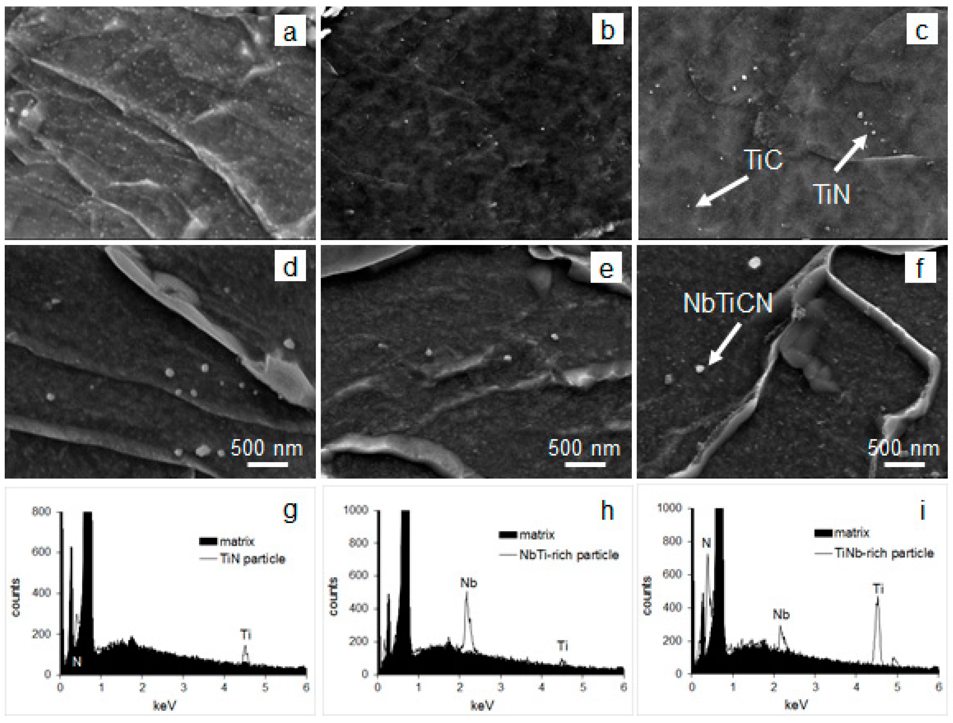
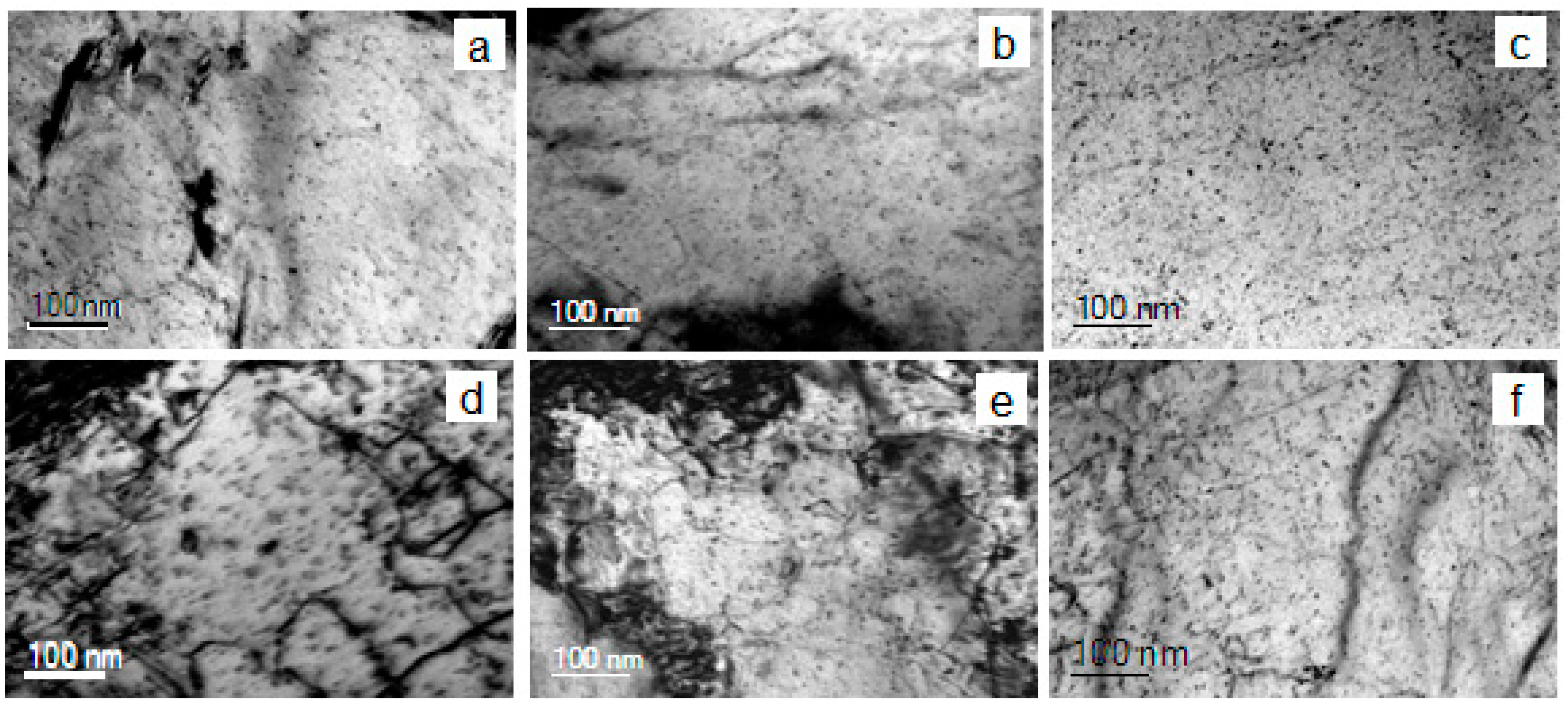
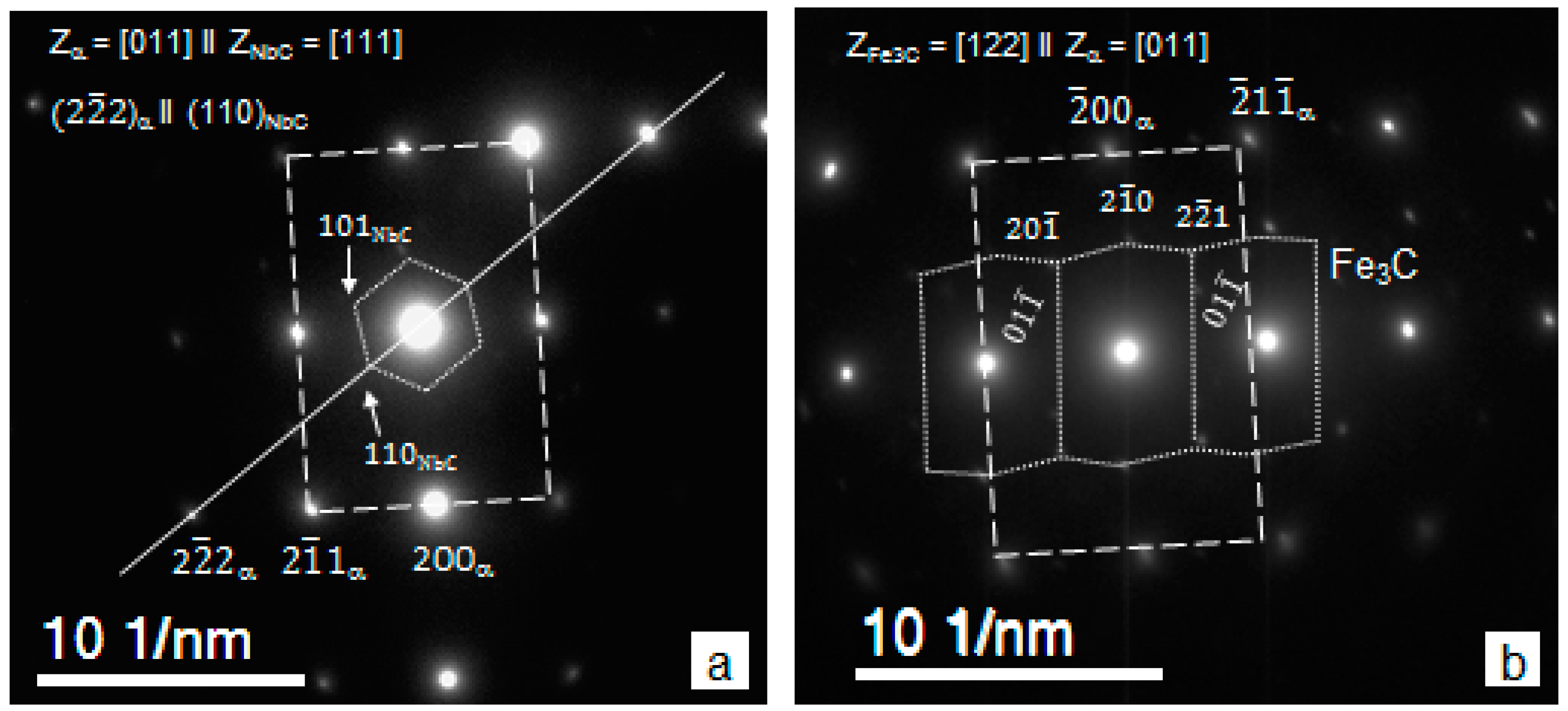
SEM imaging has shown the presence of 20–70 nm precipitates in the Ti-steel and 20–140 nm ones in the MoNbTi-steel (Figure 6a–f). EDS analysis has proven the particles to be of TiN and TiC type in the Ti-steel (Figure 6g) and NbTiCN and NbC type in the MoNbTi-steel (Figure 6h,i). The relative amount of Ti and Nb in the NbTiCN particles is believed to vary, as the Ti and Nb energy peaks on EDS spectra were of different height (compare Figure 6h,i). TEM imaging revealed presence of 2–20 nm particles in both steels in all processing conditions (Figure 7). Due to their small sizes, the EDS analysis of particles was unsuccessful. Thus, their type was identified using selected area diffraction and measurement of unit cell sizes. This approach has shown the 2–20 nm particles to be TiC and Fe3C in the Ti-steel, and NbC and Fe3C in the MoNbTi-steel. Selected examples of the diffraction analysis are presented in Figure 8. The TiC lattice parameter was measured to be a = 0.433–0.436 nm, which is in good agreement with the previously reported value of 0.432–0.433 [62,63]. The measured NbC lattice parameter of a = 0.446 nm was also in the range of previously reported values of 0.436–0.450 nm [64,65,66]. TiC and NbC particles (in the Ti- and MoNbTi-steels, respectively) exhibited [011]matrix || [111]carbide and ()matrix || (110)carbide orientation relationship with the matrix (Figure 8a), which is a variant of Kurdjumov–Sachs orientation relationship [67]. This indicates that TiC and NbC particles precipitated in austenite. A diffraction pattern showing the [122]Fe3C || [011]matrix orientation relationship in Figure 8b originated from the orthorhombic crystal lattice, characteristic for Fe3C particles [68,69]; and the measured spacing of 0.269 nm was in good agreement with nm calculated based on the Fe3C lattice parameters a = 0.674 nm, b = 0.453 nm and c = 0.509 nm [70].
Analysis of the particle parameters has shown the following for Ti-steel (Table 1):
- The maximum of >20 nm particle number density and volume fraction, maximum of relative percentage of TiC in the >20 nm particle size range, absence of TiC in the <20 nm size range, and minimum of matrix unit cell size (associated with minimum concentration of solid solute atoms in the matrix [71]) were observed for route A. These data indicate a pronounced strain induced precipitation of TiC occurring in austenite when two high temperature deformations, at 1100 and 975 °C, were applied;
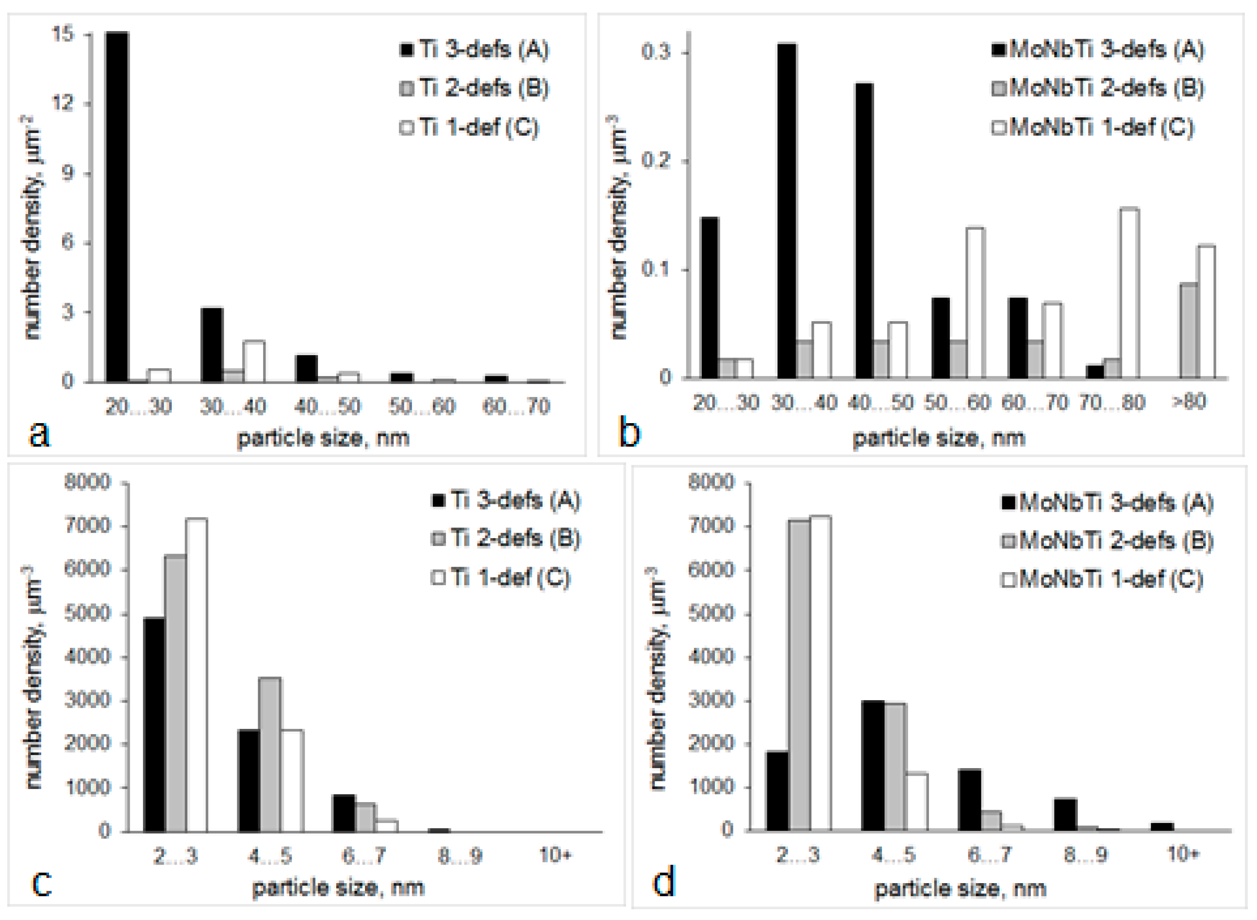
- With elimination of deformation at 1100 °C (route B), the >20 nm particle number density decreased by almost 30 times (note the particle size distribution variation in Figure 9a), the average particle size increased, relative amount of >20 nm TiC particles decreased to 25% (from 41% for route A), the <20 nm particle number density increased by 1.3 times (note the particle size distribution variation in Figure 9c), amongst <20 nm particles the TiC ones were identified in addition to Fe3C, the matrix unit cell size increased to 0.305 nm (from 0.296 nm for route A). These suggest a substantial decrease in strain-induced precipitation in austenite, compared to route A, with more Ti and C available for precipitation of <20 nm particles.
- Without high temperature deformation (route C) the number density of >20 nm particles increased due to static precipitation of TiN, although precipitation of TiC in austenite continued to decrease (note a decrease in the relative amount of TiC in the >20 nm particle size range), the number density and volume fraction of <20 nm particles slightly decreased (by about 6% compared to route B), although the number density of <20 nm particles was 22% higher than for route A, the matrix unit cell size was of intermediate value between routes A and B. These data mean that route C gives a “balanced distribution” of Ti between >20 nm, <20 nm particles and solid solution.
In the MoNbTi-steel, the following variations in precipitation took place (Table 1):
- The route A resulted in the highest number density of >20 nm particles, the largest fraction of NbC in the >20 nm particle size range, and the lowest number density of <20 nm particles, although the average size of <20 nm particles and their volume fraction were the highest compared to other routes (remember that <20 nm NbC precipitated in austenite). Similarly, to Ti-steel, these indicate a substation strain-induced precipitation in austenite for route A, in particular precipitation of NbC in addition to NbTiCN;
- With elimination of deformation at 1100 °C (route B) the number density of >20 nm particles decreased by thre times (Figure 9b), although the average size and fraction of TiNbCN increased; the number density of <20 nm particles increased by almost one and a half times (and by almost four times in the 2–3 nm size range, Figure 9d); the matrix unit cell size showed a certain decrease (which may follow a decrease in the solid solute concentrations). These data for route B support a slower strain-induced precipitation in austenite, growth of Ti-core particles via deposition of Nb containing shell, and quite significant precipitation of <20 nm particles (NbC in austenite and Fe3C in the ferrite temperature field);
- Without high temperature deformation (route C), the average size of >20 nm particles further increased, their area fraction increased by 2.7 times compared to route B, the relative amount of coarse TiNbCN continued to rise; the average size, number density and volume fraction of <20 nm particles decreased compared to route B (although the number density of 2–3 nm particles was as high as for route B), and the matrix unit cell size slightly increased. These mean that static precipitation of NbTiCN and growth of TiNbCN particles in austenite were significant, some static precipitation of NbC in austenite took place, Fe3C precipitation was significant, and the solid solution might be enriched in Mo, Nb and C.
With respect to the effect of steel composition on precipitation for the same processing schedule, both steels showed domination of (i) strain-induced precipitation in austenite for route A resulting in high number densities of >20 nm particles, (ii) <20 nm particle precipitation for route B, and (iii) enrichment of solid solution for route C. However, the particle number density in all size ranges was higher in the Ti-steel (except for the <20 nm particles for route B), although this steel contained a lower Ti concentration (0.012 wt.%, compared to 0.021 wt.% in the MoNbTi-steel) and no Nb. Obviously, a higher Carbon content in the Ti-steel (0.095 wt.% compared to 0.081 wt.% in the MoNbTi-steel) enhanced precipitation of TiC, and presence of Mo in the MoNbTi-steel retarded the particle nucleation. Increased solubility of Ti and Nb in austenite with Mo addition was reported previously [72,73,74].
3.3. Dislocation Structure
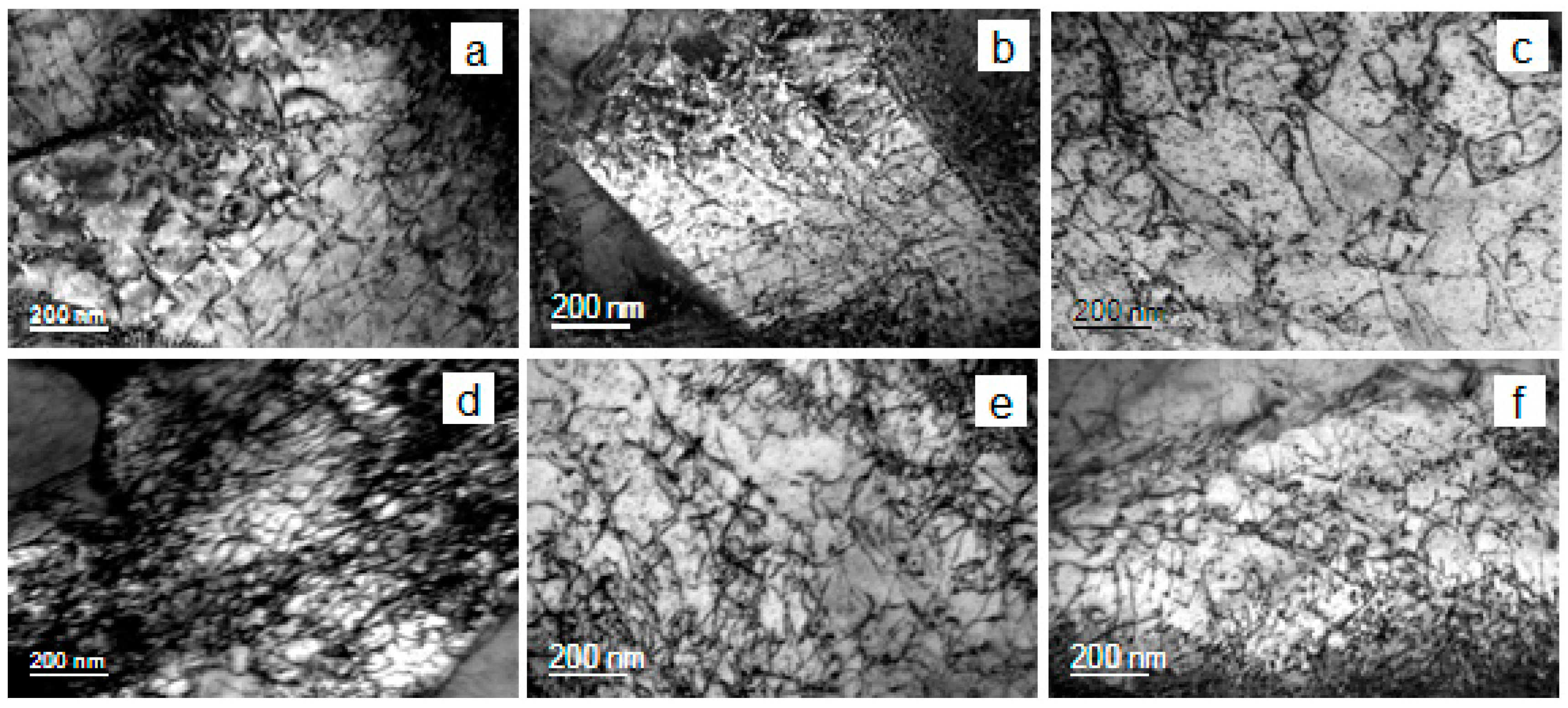
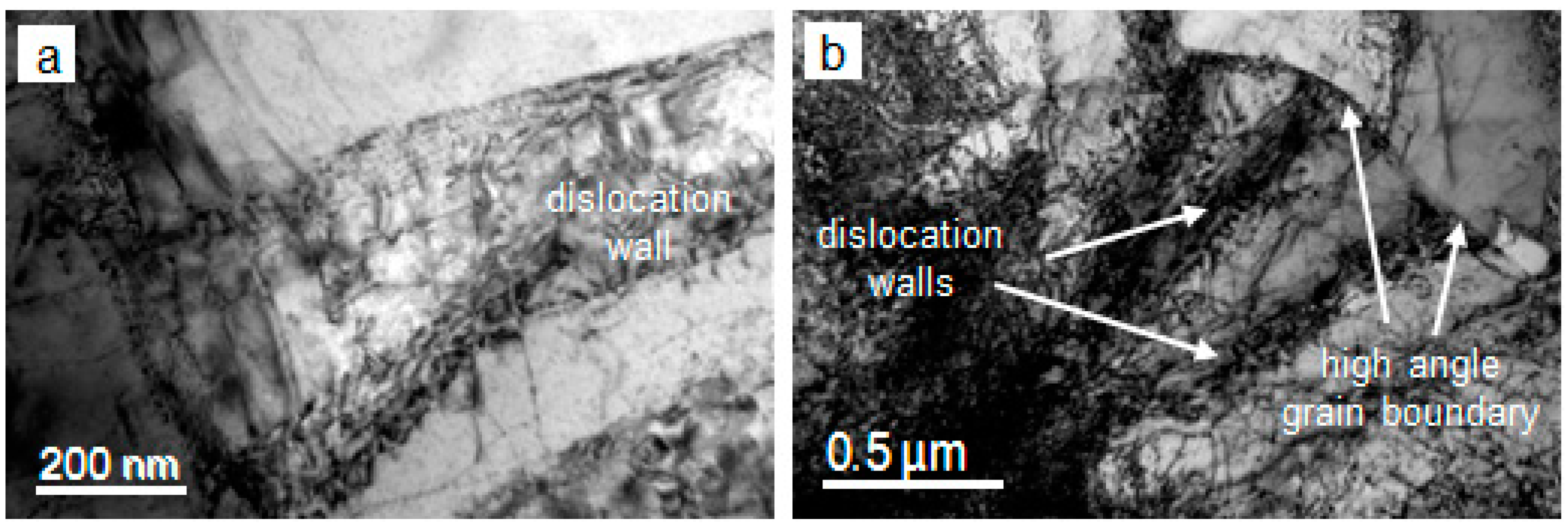
In both steels the dislocation structure consisted of dense dislocation networks, with numerous knots and tangles (Figure 10). The average dislocation density was 1.9–2.6 × 10¹⁴ m−2 in the Ti-steel and 3.2–4.3 × 10¹⁴ m−2 in the MoNbTi-steel (Table 1). Up to two times higher dislocation density in the MoNbTi-steel was an insignificant difference to what might be expected from the steel composition variation. This can be explained by recovery taking place during holding after the warm deformation cycle. For each steel the variation in dislocation density with processing was insignificant. Obviously, the final dislocation density was more affected by warm deformation and holding (which was similar for all processing schedules) than by hot deformation. The dislocation walls have been observed in both steels for all processing conditions (Figure 11). They could develop following dislocation polygonisation during holding after the warm deformation; this requires a more detailed investigation.
4. Effect of Processing on Mechanical Properties
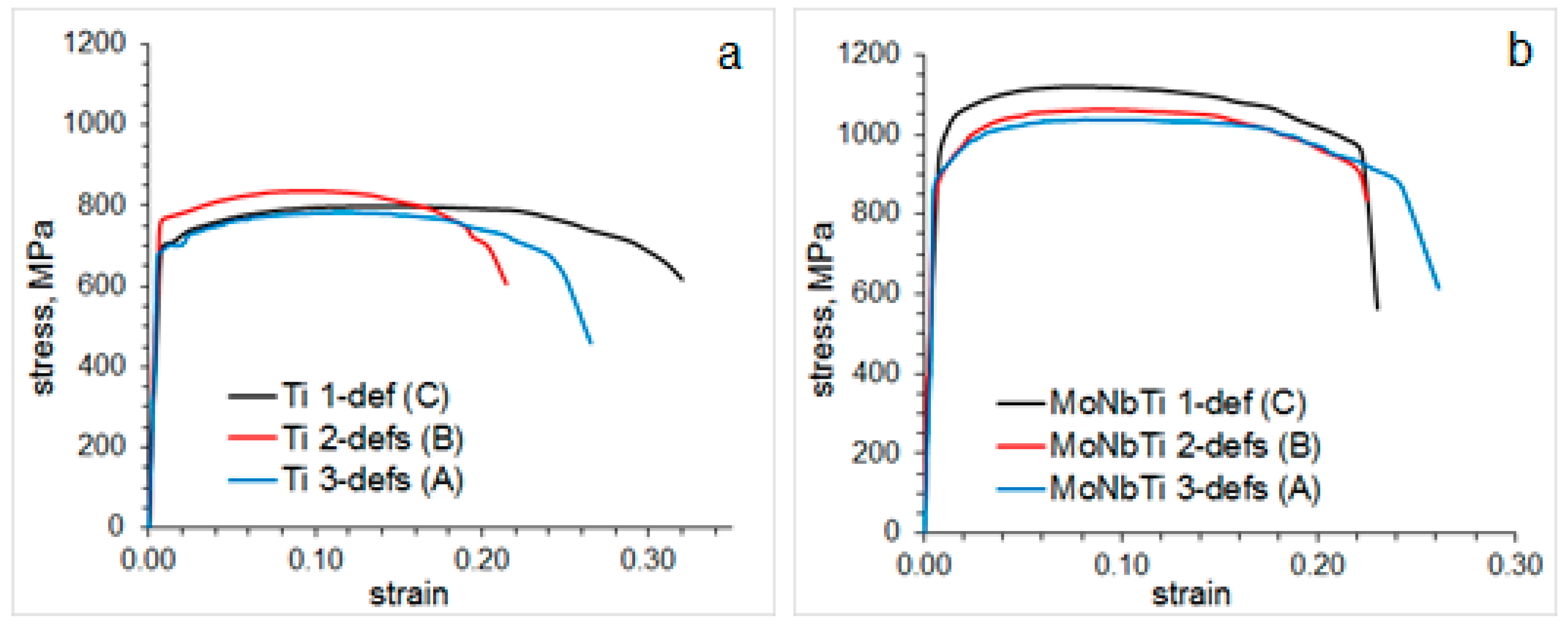
The AC2WD-technology studied here in laboratory conditions produced significantly higher strength, with simultaneous high elongation, compared to the values usually achieved for similar steel compositions after contemporary processing. Thus, the yield stress (YS), ultimate tensile strength (UTS) and elongation to failure in Ti-steel were in the range of 686–765 MPa, 783–836 MPa and 20–30%, respectively; and these in MoNbTi-steel were in the range of 880–950 MPa, 1037–1120 MPa and 22–24%, respectively (Figure 12, Table 2). After contemporary processing, i.e., completed rolling in the austenite temperature field followed by cooling at moderate rates, properties at the level of YS = 645–685 MPa, UTS = 715–750 MPa and 20–24% of elongation were reported in a 0.08C-0.08 wt.% Ti steel [75]; and YS = 720 MPa, UTS = 808 MPa and 23.5% of elongation were observed in a 0.05C-0.104 wt.% Ti steel [76]. As can be seen, for Ti-microalloyed grades the AC2WD-technology may overcome strength by 100 MPa (with similar ductility) at 6.7 times lower Ti content and overcome strength by 30 MPa (with similar ductility) at 8.7 times lower Ti content. For the MoNbTi-microalloyed grades, the following properties were reported after contemporary processing: YS = 619–731 MPa, UTS = 682–764 MPa and 17–19% of elongation for 0.075C-0.079Mo-0.055Nb-0.06Ti steel [77]; and YS = 734 MPa, UTS = 807 MPa and 24% of elongation for 0.047C-0.20Mo-0.082Ti steel [78]. Compared to these, the AC2WD-technology provides 200–300 MPa strength increase (with similar ductility) for lower microalloying element concentrations and a more simple processing schedule (in particular, a decreased number of deformation passes). So remarkable improvements in mechanical properties can be associated with three microstructure developments inherent for the AC2WD-technology: (i) slow strain induced precipitation in austenite, due to decreased deformation in the austenite temperature field, saves microalloying elements, carbon and nitrogen for low temperature precipitation and solid solution strengthening; (ii) accelerated cooling through the intercritical temperature region helps the formation of the acicular ferrite/bainite (depending on steel composition) microstructure with fine grain size; and (iii) warm deformation followed by holding leads to appearance of deformation bands and dislocation walls, which reduce the distance of dislocation free-pass and contribute to the grain refinement effect.
This work has shown a dependence of the mechanical properties on the number of deformation passes in the austenite temperature field. In addition, the processing schedule, which can provide maximum strength, varied with steel composition. Thus, the maximum strength of Ti-steel was achieved for the schedule with one pass of austenite deformation (route B). This route provided maximum precipitation strengthening and solid solution strengthening via a decreased number density and area fraction of >20 nm particles, maximum number density of <20 nm particles and maximum concentration of solid solute atoms (note the most expanded matrix unit cell size). Absence of austenite deformation (route C) resulted in a similarly fine-grained microstructure and the highest ductility. However, the TiN and TiC particle coarsening in austenite led to a lower <20 nm particle number density (lower precipitation strengthening) and, possibly, lower C and N concentrations in the matrix (lower solid solution strengthening). The maximum strength of MoNbTi-steel was achieved when no deformation of cast microstructure was applied in the austenite temperature field (route C). For this steel chemistry, route C provided the highest solid solute concentrations, although not the highest number density of <20 nm particles. Obviously, in the MoNbTi-steel, the role of solid solute atoms was greater than in the Ti-steel. In addition to C and N, Mo and Nb in solution could contribute to the solid solution strengthening effect. Thus, their retention in the form of atoms, rather than in the form of precipitates, was crucial for the steel strength. The highest elongation and toughness of MoNbTi-steel, although the lowest strength, were observed for the processing route with two hot deformation stages, i.e., route A. This coincided with the largest bainitic ferrite area width and minimal second phase fraction. In practice, a thin strip manufacturing facility could be recommended to operate with two rolling stands. Especially if due to economic reasons, lesser microalloyed steel compositions will be produced.
5. Conclusions
Investigation of the chemistry-processing-microstructure-properties relationship in the new technology based on austenite conditioning followed by accelerated cooling and warm deformation has led to the following conclusions:
- For the studied steel chemistry examples, new technology provided the yield stress in the range of 686–765 MPa and 880–950 MPa, ultimate tensile strength in the range of 783–836 MPa and 1037–1120 MPa, and simultaneously high elongation of 20–30% and 22–24% in the steels containing 0.095C-0.012Ti and 0.081C-0.1Mo-0.064Nb-0.021Ti (wt.%), respectively. This is 100–300 MPa superior to strength levels obtained using contemporary processing of steels with several times higher microalloying element contents. So remarkable property improvement can be related to minimal particle coarsening in austenite, optimum microalloying elements distribution between fine particles and solid solution, and formation of deformation bands and dislocation walls reducing the dislocation free-pass and contributing to the grain refinement effect.
- Processing route (in particular, two, one or no deformation passes in the austenite temperature field) leading to the maximum steel strength varied with steel composition. A lower microalloyed steel (Ti-steel) showed its maximum strength for the processing route with one pass of hot deformation of austenite and one pass of warm deformation of bainite. However, a higher microalloyed steel (MoNbTi-steel) showed its maximum strength for the processing route with no deformation of austenite. This is related to a variation in strengthening mechanisms in steels with different chemistry: in addition to grain refinement, critical for both compositions, precipitation strengthening was the second dominating in the Ti-steel, and the solid solution strengthening was the second in the MoNbTi-steel.
Author Contributions
A.K. conceived the idea and carried out the technology modelling in Gleeble, microstructure characterisation, mechanical properties testing and the manuscript writing. O.M. prepared the samples, conducted optical and scanning electron microscopy, assisted in tensile testing, and significantly contributed to the discussion of results and manuscript writing.
Acknowledgments
This project was financially supported by the Faculty of Engineering and Information Science of the University of Wollongong (Australia). The microscopy was carried out using JEOL JSM-7001F FEGSEM (supported by grant LE0882613) and JEOL JEM-2011 TEM (supported by grant LE0237478) microscopes at the Electron Microscopy Centre at the University of Wollongong.
Conflicts of Interest
The authors declare no competing interests.
Appendix A. Materials and Methods
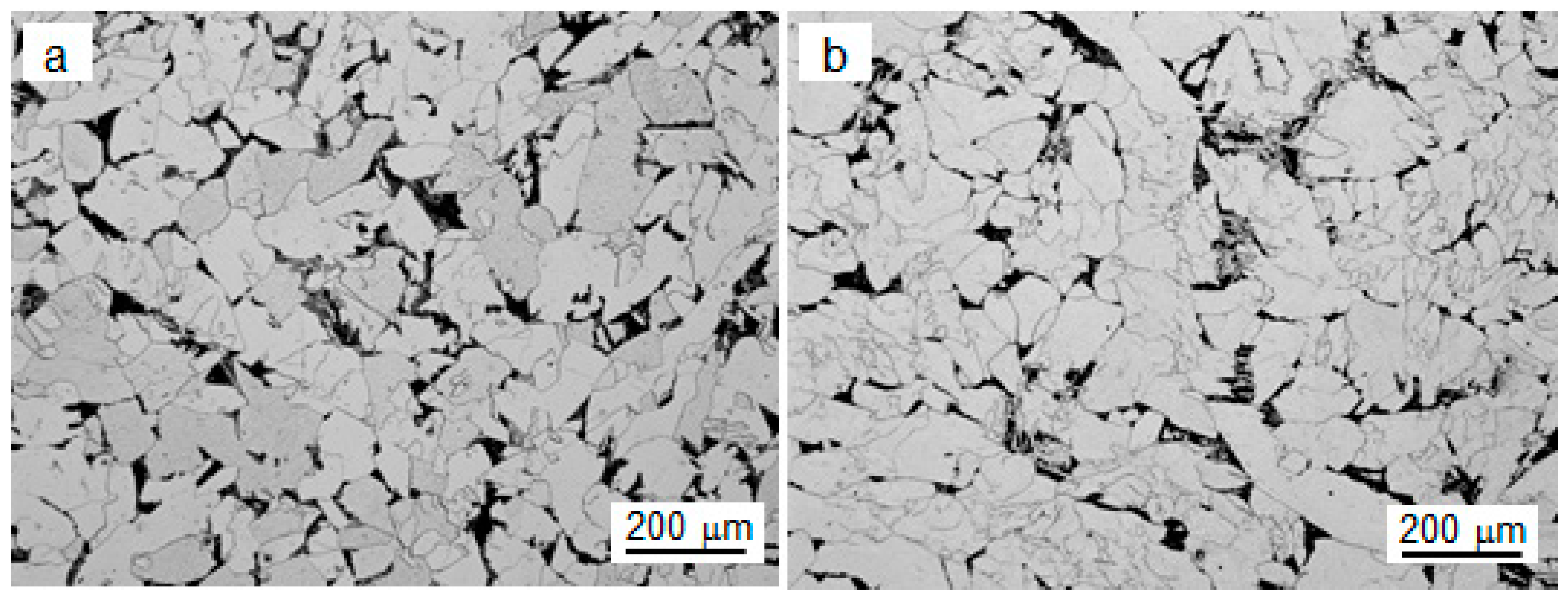
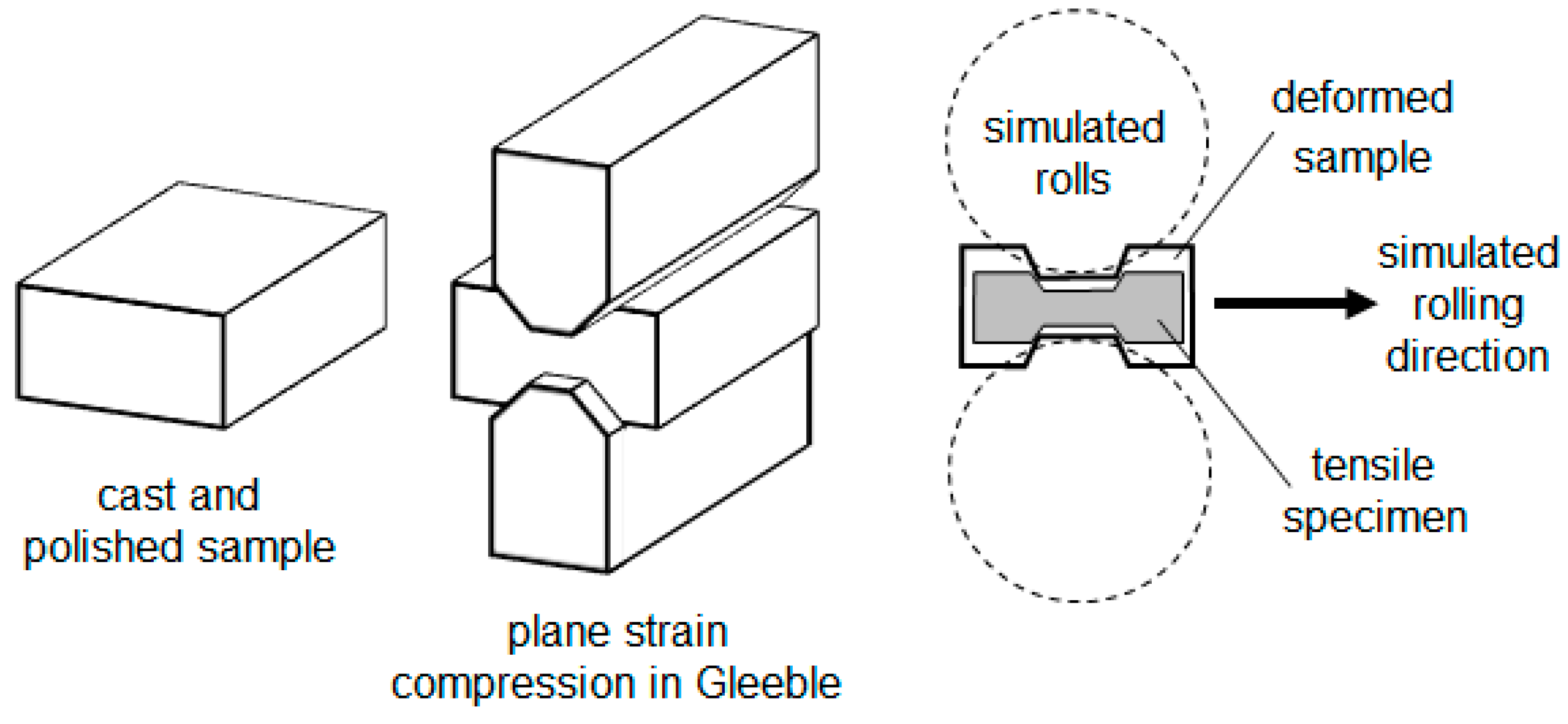
The technology development was carried out via simulation of thermomechanical processing in Gleeble 3500 (manufactured by Dynamic Systems Inc., Poestenkill, NY, USA). Two steels were used to test the technology: 0.095C, 1.3Mn, 0.26Si, 0.018Ni, 0.013Cr, 0.022Cu, 0.039Al, 0.012Ti, 0.001S, 0.012P, and 0.0043N (wt.%), denoted as Ti-steel, and 0.081C, 1.20Mn, 0.27Si, 0.021Ni, 0.019Cr, 0.1Mo, 0.016Cu, 0.037Al, 0.064Nb, 0.021Ti, 0.001S, 0.012P, and 0.0047N (wt.%), denoted as MoNbTi-steel. The steels have been cast by BlueScope Steel Ltd (Melbourne, Australia) using the same processing parameters for both steels, and provided in the form of 10 × 15 × 20 mm3 size samples. Ambient temperature microstructures of the as-received cast samples are shown in Figure A1. Measurements of solidification rate were not conducted, as the effect of solidification rate on microstructure and mechanical properties was outside of the current project scope. Although, the observation of microstructures in Figure A1 suggests the cooling rate through the austenite-to-ferrite transformation temperature field could be around 5–10 °C s−1. Microstructure characterisation was carried out using optical, scanning (SEM) and transmission (TEM) electron microscopy. Optical and SEM sample preparation included polishing with SiC papers and diamond suspensions, and etching with 5% Nital. Foils for TEM were prepared by hand polishing followed by ion milling on a Gatan PIPS machine (manufactured by Gatan, Pleasanton, CA, USA). Optical microscopy was conducted on a Leica DM6000M microscope (manufactured by Leica Microsystems, Wetzlar, Germany). SEM was carried out using a JEOL 7001F FEG scanning electron microscope (manufactured by JEOL, Tokyo, Japan) operating at 10 kV. The EDS semi-quantitative point analysis was carried out for about 30 particles for each of six studied conditions using an AZtec 2.0 Oxford SEM EDS system (manufactured by Oxford Instruments, Abingdon, UK). TEM was conducted on a JEOL JEM2010 TEM microscope (manufactured by JEOL, Tokyo, Japan). The foil thickness was measured to be ~120 nm. The precipitates type was analysed using selected area diffraction. For statistical analysis, 200–350 particles were imaged for each condition. Imaging of dislocation structure was performed for the beam direction close to [011] grain zone axis. Tensile testing was carried out on a Kammrath and Weiss GmbH tensile stage. Testing was performed using 2 mm wide, 0.8 mm thick and 5 mm gauge length flat specimens. The specimens were cut in the plane parallel to the compression direction perpendicular to the Gleeble anvil plane. Such a cutting method assured the tensile direction was parallel to the one which represents the rolling direction in Gleeble simulation (Figure A2). The constant crosshead speed of 5 μm s−1 was applied and resulted in 1 × 10⁻³ s−1 strain rate. Two specimens were tested for each condition.
Figure A1.
Representative optical images of microstructures in as-received samples of (a) Ti-steel and (b) MoNbTi-steel.
Figure A1.
Representative optical images of microstructures in as-received samples of (a) Ti-steel and (b) MoNbTi-steel.

Figure A2.
Scheme of Gleeble simulation of the rolling process.

References
- Rankin, J. Energy Use in Metal Production. In Proceedings of the 4th Annual High Temperature Processing Symposium, Swinburne University, Melbourne, Australia, 6–7 February 2012. [Google Scholar]
- World Steel Association. Energy Use in the Steel Industry. Available online: http://www.worldsteel.org/publications/fact-sheets.html (accessed on 26 July 2017).
- Castrip LLC. The Castrip® Advantage. Available online: http://www.castrip.com/Advantage/advantage.html (accessed on 23 August 2018).
- Shimizu, Y.; Iwatani, J.; Hasai, J. Compact hot strip mill for high quality strip production. Mitsubishi Heavy Ind. Tech. Rev. 2000, 37, 48–51. [Google Scholar]
- Hensger, K.-E. Processing of advanced structural steels on CSP plants. Metalurgija 2002, 41, 183–190. [Google Scholar]
- DeArdo, A.J.; Marraccini, R.; Hua, M.J.; Garcia, C.I. Optimization of Nb HSLA microstructure using advanced thermomechanical processing in a CSP plant. Mater. Sci. Forum 2007, 539–543, 28–35. [Google Scholar] [CrossRef]
- Stubbles, J.R. The Minimill Story. Metall. Mater. Trans. B 2009, 40, 134–144. [Google Scholar] [CrossRef] [Green Version]
- Rosenthal, D.; Kraemer, S.; Klein, C.; Geerkens, C.; Mueller, J. 20 years of CSP: Success story of an extraordinary technology. Stahl und Eisen 2009, 129, 73–89. [Google Scholar]
- Patra, P.; Sam, S.; Singhai, M.; Kant, N. Study on the Production of Ultra High Strength Steel (UHSS) in Thin Slab Caster. SAE Tech. Pap. 2014. [Google Scholar] [CrossRef]
- Ge, S.; Isac, M.; Guthrie, R.I.L. Progress of strip casting technology for steel: Historical developments. ISIJ Int. 2012, 52, 2109–2122. [Google Scholar] [CrossRef]
- Killmore, C.R.; Edelman, D.G.; Carpenter, K.R.; Kaul, H.R.; Williams, J.G.; Campbell, P.C.; Blejde, W.N. Recent product developments with ultra-thin cast strip products produced by the CASTRIP® Process. Mater. Sci. Forum 2010, 654–656, 198–201. [Google Scholar] [CrossRef]
- Xie, K.Y.; Zheng, T.; Cairney, J.M.; Kaul, H.; Williams, J.G.; Barbaro, F.J.; Killmore, C.R.; Ringer, S.P. Strengthening from Nb-rich clusters in a Nb-microalloyed steel. Scr. Mater. 2012, 66, 710–713. [Google Scholar] [CrossRef]
- Wang, Z.; Carpenter, K.; Chen, Z.; Killmore, C. The effect of cooling rate and coiling temperature on the niobium retention in Ultra-Thin Cast Strip steel. Mater. Sci. Eng. A 2017, 700, 234–240. [Google Scholar] [CrossRef]
- Xiong, Z.P.; Kostryzhev, A.G.; Stanford, N.E.; Pereloma, E.V. Effect of deformation on microstructure and mechanical properties of dual phase steel produced via strip casting simulation. Mater. Sci. Eng. A 2016, 651, 291–305. [Google Scholar] [CrossRef] [Green Version]
- Xiong, Z.P.; Kostryzhev, A.G.; Chen, L.; Pereloma, E.V. Microstructure and mechanical properties of strip cast TRIP steel subjected to thermo-mechanical simulation. Mater. Sci. Eng. A 2016, 677, 356–366. [Google Scholar] [CrossRef] [Green Version]
- Xiong, Z.P.; Saleh, A.A.; Kostryzhev, A.G.; Pereloma, E.V. Strain-induced ferrite formation and its effect on mechanical properties of a dual phase steel produced using laboratory simulated strip casting. J. Alloys Compd. 2017, 721, 291–306. [Google Scholar] [CrossRef]
- Smith, Y.E.; Siebert, C.A. Continuous cooling transformation kinetics of thermomechanically worked low-carbon austenite. Metall. Trans. 1971, 2, 1711–1725. [Google Scholar]
- Priestner, R.; Biring, M.S. Transformation of low-carbon austenite after small plastic strains. Met. Sci. 1973, 7, 60–64. [Google Scholar] [CrossRef]
- Park, J.K.; Kim, K.H.; Chung, J.H.; Ok, S.Y. Deformation-induced asutenite to ferrite massive transformation in medium carbon steel. Metall. Mater. Trans. A 2008, 39, 235–242. [Google Scholar] [CrossRef]
- Song, R.; Ponge, D.; Raabe, D.; Speer, J.G.; Matlock, D.K. Overview of processing, microstructure and mechanical properties of ultrafine grained bcc steels. Mater. Sci. Eng. A 2006, 441, 1–17. [Google Scholar] [CrossRef]
- DeArdo, A.J. Metallurgical basis for thermomechanical processing of microalloyed steels. Ironmak. Steelmak. 2001, 28, 138–144. [Google Scholar] [CrossRef]
- Cizek, P.; Wynne, B.P.; Davies, C.H.J.; Muddle, B.C.; Hodgson, P.D. Effect of composition and austenite deformation on the transformation characteristics of low-carbon and ultralow-carbon microalloyed steels. Metall. Mater. Trans. A 2002, 33, 1331–1349. [Google Scholar] [CrossRef]
- Bakkaloğlu, A. Effect of processing parameters on the microstructure and properties of an Nb microalloyed steel. Mater. Lett. 2002, 56, 200–209. [Google Scholar] [CrossRef]
- Sun, L.; Wynne, B.P.; Palmiere, E.J. Effect of austenite deformation on recrystallization behaviour in an X70 microalloyed steel. Adv. Mater. Res. 2010, 89–91, 721–726. [Google Scholar] [CrossRef]
- Hodgson, P.D.; Hickson, M.R.; Gibbs, R.K. Ultrafine ferrite in low carbon steel. Scr. Mater. 1999, 40, 1179–1184. [Google Scholar] [CrossRef]
- Mabuchi, H.; Hasegawa, T.; Ishikawa, T. Metallurgical features of steel plates with ultra fine grains in the surface layers and their formation mechanism. ISIJ Int. 1999, 39, 477–485. [Google Scholar] [CrossRef]
- Yang, Z.; Wang, R. Formation of ultra-fine grain structure of plain low carbon steel through deformation induced ferrite transformation. ISIJ Int. 2003, 43, 761–766. [Google Scholar] [CrossRef]
- Hong, S.C.; Lim, S.H.; Hong, H.S.; Lee, K.J.; Shin, D.H.; Lee, K.S. Effects of Nb on strain induced ferrite transformation in C-Mn steel. Mater. Sci. Eng. A 2003, 355, 241–248. [Google Scholar] [CrossRef]
- Wang, R.Z.; Lei, T.C. Dynamic recrystallization of ferrite in a low carbon steel during hot rolling in the (F + A) two-phase range. Scr. Metall. Mater. 1994, 31, 1193–1196. [Google Scholar] [CrossRef]
- Ohmori, A.; Torizuka, S.; Nagai, K.; Koseki, N.; Kogo, Y. Effect of deformation temperature and strain rate on evolution of ultrafine grained structure through single-pass large-strain warm deformation in a low carbon steel. Mater. Trans. 2004, 45, 2224–2231. [Google Scholar] [CrossRef]
- Song, R.; Ponge, D.; Raabe, D. Mechanical properties of an ultrafine grained C–Mn steel processed by warm deformation and annealing. Acta Mater. 2005, 53, 4881–4892. [Google Scholar] [CrossRef]
- Li, L.; Yang, W.; Sun, Z. Dynamic recrystallization of ferrite in a low-carbon steel. Metall. Mater. Trans. A 2006, 37, 609–619. [Google Scholar]
- Hou, H.; Chen, Q.; Liu, Q.; Dong, H. Grain refinement of a Nb–Ti microalloyed steel through heavy deformation controlled cooling. J. Mater. Process. Technol. 2003, 137, 173–176. [Google Scholar] [CrossRef]
- Park, K.-T.; Han, S.Y.; Ahn, B.D.; Shin, D.H.; Lee, Y.K.; Um, K.K. Ultrafine grained dual phase steel fabricated by equal channel angular pressing and subsequent intercritical annealing. Scr. Mater. 2004, 51, 909–913. [Google Scholar] [CrossRef]
- Ueji, R.; Tsuji, N.; Minamino, Y.; Koizumi, Y. Ultragrain refinement of plain low carbon steel by cold-rolling and annealing of martensite. Acta Mater. 2002, 50, 4177–4189. [Google Scholar] [CrossRef]
- Azevedo, G.; Barbosa, R.; Pereloma, E.V.; Santos, D.B. Development of an ultrafine grained ferrite in a low C–Mn and Nb–Ti microalloyed steels after warm torsion and intercritical annealing. Mater. Sci. Eng. A 2005, 402, 98–108. [Google Scholar] [CrossRef]
- Tsuji, N.; Ito, Y.; Saito, Y.; Minamino, Y. Strength and ductility of ultrafine grained aluminum and iron produced by ARB and annealing. Scr. Mater. 2002, 47, 893–899. [Google Scholar] [CrossRef]
- Kostryzhev, A.G.; Marenych, O.O. Superior mechanical properties of microalloyed steels processed via a new technology based on austenite conditioning followed by warm deformation. Mater. Sci. Eng. A 2017, 688, 16–19. [Google Scholar] [CrossRef]
- Aaronson, H.I.; Reynolds, W.T.; Purdy, G.R. The incomplete transformation phenomenon in steel. Metall. Mater. Trans. A 2006, 37, 1731–1745. [Google Scholar] [CrossRef]
- Humphreys, E.S.; Fletcher, H.A.; Hutchins, J.D.; Garratt-Reed, A.J.; Reynolds, W.T.; Aaronson, H.I.; Purdy, G.R.; Smith, G.D.W. Molybdenum accumulation at ferrite: Austenite interfaces during isothermal transformation of an Fe-0.24 pct C-0.93 pct Mo alloy. Metall. Mater. Trans. A 2004, 35, 1223–1235. [Google Scholar] [CrossRef]
- Kong, J.; Xie, C. Effect of molybdenum on continuous cooling bainite transformation of low-carbon microalloyed steel. Mater. Des. 2006, 27, 1169–1173. [Google Scholar] [CrossRef]
- Hu, H.; Xu, G.; Zhou, M.; Yuan, Q. Effect of Mo content on microstructure and property of low-carbon bainitic steels. Metals 2016, 6, 173. [Google Scholar] [CrossRef]
- Mintz, B.; Banerjee, J.R.; Banks, K.M. Regression equation for Ar3 temperature for coarse grained as cast steels. Ironmak. Steelmak. 2011, 38, 197–203. [Google Scholar] [CrossRef]
- Lee, Y.K.; Hong, J.-M.; Choi, C.S.; Lee, J.K. Continuous cooling transformation temperatures and microstructures of Niobium bearing microalloyed steels. Mater. Sci. Forum 2005, 475–479, 65–68. [Google Scholar]
- Chen, Y.; Zhang, D.; Liu, Y.; Li, H.; Xu, D. Effect of dissolution and precipitation of Nb on the formation of acicular ferrite/bainite ferrite in low-carbon HSLA steels. Mater. Charact. 2013, 84, 232–239. [Google Scholar] [CrossRef]
- Tamehiro, H.; Murata, M.; Habu, R.; Nagumo, M. Optimum microalloying of Niobium and Boron in HSLA Steel for thermomechanical processing. Trans. Iron Steel Inst. Jpn. 1987, 27, 120–129. [Google Scholar] [CrossRef]
- Carpenter, K.R.; Killmore, C.R. The effect of Nb on the continuous cooling transformation curves of ultra-thin strip CASTRIP© steels. Metals 2015, 5, 1857–1877. [Google Scholar] [CrossRef]
- Barbaro, F.J.; Krauklis, P.; Easterling, K.E. Formation of acicular ferrite at oxide particles in steels. Mater. Sci. Technol. 1989, 5, 1057–1068. [Google Scholar] [CrossRef]
- Tamura, I.; Ouchi, C.; Tanaka, T.; Sekine, H. Thermomechanical Processing of High Strength Low Alloy Steels; Butterworths: London, UK, 1988. [Google Scholar]
- Grajcar, A.; Opiela, M. Influence of plastic deformation on CCT-diagrams of low-carbon and medium-carbon TRIP-steels. J. Achiev. Mater. Manuf. Eng. 2008, 29, 71–78. [Google Scholar]
- Wang, X.; Du, L.; Xie, H.; Di, H.; Gu, D. Effect of deformation on continuous cooling phase transformation behaviors of 780 MPa Nb-Ti ultra-high strength steel. Steel Res. Int. 2011, 82, 1417–1424. [Google Scholar] [CrossRef]
- AlShahrani, A.M. The Effects of Niobium Segregation and Dynamic Recrystallisation on Microstructural Homogeneity of Microalloyed Steels. Ph.D. Thesis, University of Wollongong, Wollongong, Australia, 2013. [Google Scholar]
- Lambers, H.-G.; Tschumak, S.; Maier, H.J.; Canading, D. Role of austenitization and pre-deformation on the linetics of the isothermal bainitic transformation. Metall. Mater. Trans. A 2009, 40, 1355–1366. [Google Scholar] [CrossRef]
- Bhadeshia, H.K.D.H. Bainite in Steels; IOM Communications: London, UK, 2001; pp. 23–25. [Google Scholar]
- Larn, R.H.; Yang, J.R. The effect of compressive deformation of austenite on the bainitic ferrite transformation in Fe-Mn-Si-C steels. Mater. Sci. Eng. A 2000, 278, 278–291. [Google Scholar] [CrossRef]
- Andrade, H.L.; Akben, M.G.; Jonas, J.J. Effect of molybdenum, niobium, and vanadium on static recovery and recrystallization and on solute strengthening in microalloyed steels. Metall. Trans. A 1983, 14, 1967–1977. [Google Scholar] [CrossRef]
- Schambron, T.; Chen, L.; Gooch, T.; Dehghan-Manshadi, A.; Pereloma, E.V. Effect of Mo concentration on dynamic recrystallization behavior of low carbon microalloyed steels. Steel Res. Int. 2013, 84, 1191–1195. [Google Scholar] [CrossRef]
- Kwon, O.; DeArdo, A.J. Interactions between recrystallization and precipitation in hot-deformed microalloyed steels. Acta Metall. Mater. 1991, 39, 529–538. [Google Scholar] [CrossRef]
- Medina, S.F.; Quispe, A. Improved model for static recrystallization kinetics of hot deformed austenite in low alloy and Nb/V microalloyed steels. ISIJ Int. 2001, 41, 774–781. [Google Scholar] [CrossRef]
- Vervynckt, S.; Verbeken, K.; Thibaux, P.; Liebeherr, M.; Houbaert, Y. Austenite recrystallization—precipitation interaction in Niobium microalloyed steels. ISIJ Int. 2009, 49, 911–920. [Google Scholar] [CrossRef]
- Kang, S.; Yoon, S.; Lee, S.-J. Prediction of bainite start temperature in alloy steels with different grain sizes. ISIJ Int. 2014, 54, 997–999. [Google Scholar] [CrossRef]
- Teresiak, A.; Kubsch, H. X-ray investigations of high energy ball milled transition metal carbides. Nanostruct. Mater. 1995, 6, 671–674. [Google Scholar] [CrossRef]
- Nartowski, A.M.; Parkin, I.P.; MacKenzie, M.; Craven, A.J.; MacLeod, I. Solid state metathesis routes to transition metal carbides. J. Mater. Chem. 1999, 9, 1275–1281. [Google Scholar] [CrossRef]
- Morales, E.V.; Gallego, J.; Kestenbach, H.-J. On coherent carbonitride precipitation in commercial microalloyed steels. Philos. Mag. Lett. 2003, 83, 79–87. [Google Scholar] [CrossRef]
- Fors, D.H.R.; Wahnström, G. Theoretical study of interface structure and energetics in semicoherent Fe(001)/MX(001) systems (M = Sc, Ti, V, Cr, Zr, Nb, Hf, Ta; X = C or N). Phys. Rev. B 2010, 82, 195410. [Google Scholar] [CrossRef]
- Tirumalasetty, G.K.; van Huis, M.A.; Fang, C.M.; Xu, Q.; Tichelaar, F.D.; Hanlon, D.N.; Sietsma, J.; Zandbergen, H.W. Characterization of NbC and (Nb, Ti)N nanoprecipitates in TRIP assisted multiphase steels. Acta Mater. 2011, 59, 7406–7415. [Google Scholar] [CrossRef]
- He, Y.; Godet, S.; Jonas, J.J. Observations of the Gibeon meteorite and the inverse Greninger–Troiano orientation relationship. J. Appl. Cryst. 2006, 39, 72–81. [Google Scholar] [CrossRef]
- Shiozawa, H.; Bachmatiuk, A.; Stangl, A.; Cox, D.C.; Silva, S.R.; Rümmeli, M.H.; Pichler, T. Microscopic insight into the bilateral formation of carbon spirals from a symmetric iron core. Sci. Rep. 2013, 3, 1840. [Google Scholar] [CrossRef] [PubMed] [Green Version]
- Kostryzhev, A.G.; Slater, C.D.; Marenych, O.O.; Davis, C.L. Effect of solidification rate on microstructure evolution in dual phase microalloyed steel. Sci. Rep. 2016, 6, 35715. [Google Scholar] [CrossRef] [PubMed] [Green Version]
- Andrews, K.W. Tabulation of interplanar spacings of cementite Fe3C. Acta Crystallogr. 1963, 16, 68. [Google Scholar] [CrossRef]
- Agrawal, B.K. Introduction to Engineering Materials; Tata McGraw-Hill: New Delhi, India, 1988. [Google Scholar]
- Mukherjee, S.; Timokhina, I.; Zhu, C.; Ringer, S.P.; Hodgson, P.D. Clustering and precipitation processes in a ferritic titanium-molybdenum microalloyed steel. J. Alloys Compd. 2017, 690, 621–632. [Google Scholar] [CrossRef]
- Wang, Z.; Zhang, H.; Guo, C.; Liu, W.; Yang, Z.; Sun, X.; Zhang, Z.; Jiang, F. Effect of molybdenum addition on the precipitation of carbides in the austenite matrix of titanium micro-alloyed steels. J. Mater. Sci. 2016, 51, 4996–5007. [Google Scholar] [CrossRef]
- Akben, M.G.; Bacroix, B.; Jonas, J.J. Effect of vanadium and molybdenum addition on high temperature recovery, recrystallization and precipitation behaviour of niobium-based microalloyed steels. Acta Metall. 1983, 31, 161–174. [Google Scholar] [CrossRef]
- Yi, H.-L.; Liu, Z.-Y.; Wang, G.-D.; Wu, D. Development of Ti-Microalloyed 600 MPa Hot Rolled High Strength Steel. J. Iron Steel Res. Int. 2010, 17, 54–58. [Google Scholar] [CrossRef]
- Xia, J.; Huo, X.; Li, L.; Peng, Z.; Chen, S. Development of Ti microalloyed high strength steel plate by controlling thermo-mechanical control process schedule. Mater. Res. Express 2017, 4, 126504. [Google Scholar] [CrossRef] [Green Version]
- Tang, S.; Liu, Z.Y.; Wang, G.D.; Misra, R.D.K. Microstructural evolution and mechanical properties of high strength microalloyed steels: Ultra Fast Cooling (UFC) versus Accelerated Cooling (ACC). Mater. Sci. Eng. A 2013, 580, 257–265. [Google Scholar] [CrossRef]
- Funakawa, Y.; Shiozaki, T.; Tomita, K.; Yamamoto, T.; Maeda, E. Development of high strength hot-rolled sheet steel consisting of ferrite and nanometer-sized carbides. ISIJ Int. 2004, 44, 1945–1951. [Google Scholar] [CrossRef]
Figure 1.
Schemes of processing schedules investigated: (A) with two deformations, (B) one deformation, or (C) no deformation in austenite temperature region.
Figure 1.
Schemes of processing schedules investigated: (A) with two deformations, (B) one deformation, or (C) no deformation in austenite temperature region.

Figure 2.
Optical images of microstructures in (a–c) Ti-steel and (d–f) MoNbTi-steel, after processing according to schedule (a,d) A, (b,e) B and (c,f) C (Figure 1).
Figure 2.
Optical images of microstructures in (a–c) Ti-steel and (d–f) MoNbTi-steel, after processing according to schedule (a,d) A, (b,e) B and (c,f) C (Figure 1).

Figure 3.
SEM images of microstructures in (a–c) Ti-steel and (d–f) MoNbTi-steel, after processing according to schedule (a,d) A, (b e) B and (c,f) C (Figure 1): P—pearlite, F—ferrite, M/A—martensite-austenite constituent, BF—bainitic ferrite.
Figure 3.
SEM images of microstructures in (a–c) Ti-steel and (d–f) MoNbTi-steel, after processing according to schedule (a,d) A, (b e) B and (c,f) C (Figure 1): P—pearlite, F—ferrite, M/A—martensite-austenite constituent, BF—bainitic ferrite.

Figure 4.
Schematic presentation of microstructure development in the Ti-steel with processing route (A–C); γ: austenite temperature range, α: ferrite temperature range.
Figure 4.
Schematic presentation of microstructure development in the Ti-steel with processing route (A–C); γ: austenite temperature range, α: ferrite temperature range.

Figure 5.
Schematic presentation of microstructure development in the MoNbTi-steel with processing route (A–C); γ: austenite temperature range, α: ferrite temperature range.
Figure 5.
Schematic presentation of microstructure development in the MoNbTi-steel with processing route (A–C); γ: austenite temperature range, α: ferrite temperature range.

Figure 6.
SEM images of precipitates in (a–c) Ti-steel and (d–f) MoNbTi-steel, after processing according to schedule (a,d) A, (b,e) B and (c,f) C (Figure 1) and EDS spectra of (g) TiN particle in the Ti-steel, (h) NbTi-rich particle in the MoNbTi-steel and (i) TiNb-rich particle in the MoNbTi-steel.

Figure 7.
TEM images of precipitates in (a–c) Ti-steel and (d–f) MoNbTi-steel, after processing according to schedule (a,d) A, (b,e) B and (c,f) C (Figure 1).
Figure 7.
TEM images of precipitates in (a–c) Ti-steel and (d–f) MoNbTi-steel, after processing according to schedule (a,d) A, (b,e) B and (c,f) C (Figure 1).

Figure 8.
Determination of NbC and Fe3C using TEM diffraction patterns.

Figure 9.
Variations in the (a,b) >20 nm and (c,d) <20 nm particle number density distributions with processing schedule for (a,c) Ti-steel and (b,d) MoNbTi-steel.
Figure 9.
Variations in the (a,b) >20 nm and (c,d) <20 nm particle number density distributions with processing schedule for (a,c) Ti-steel and (b,d) MoNbTi-steel.

Figure 10.
TEM images of typical dislocation structure in (a–c) Ti-steel and (d–f) MoNbTi-steel, after processing according to schedule (a,d) A, (b,e) B and (c,f) C (see Figure 1).
Figure 10.
TEM images of typical dislocation structure in (a–c) Ti-steel and (d–f) MoNbTi-steel, after processing according to schedule (a,d) A, (b,e) B and (c,f) C (see Figure 1).

Figure 11.
Dislocation walls in (a) Ti-steel and (b) MoNbTi-steel.

Figure 12.
Ambient temperature stress-strain curves for (a) Ti-steel and (b) MoNbTi-steel.


Table 1.
Microstructural parameters in the studied steels.
| Parameters | Ti-Steel | MoNbTi-Steel | |||||
|---|---|---|---|---|---|---|---|
| A | B | C | A | B | C | ||
| Optical and scanning electron microscopy | |||||||
| ferrite grain size/ bainitic ferrite area width (m) | 10.0 ± 6.4 | 4.8 ± 3.0 | 4.7 ± 2.5 | 2.5 ± 1.8 | 1.0 ± 0.5 | 0.9 ± 0.4 | |
| second phase | average size (m) | 3.3 | 1.7 | 1.9 | 1.2 | 1.1 | 1.8 |
| Fraction (%) | 2.5 | 3.2 | 4.3 | 5.5 | 7.7 | 13.0 | |
| Scanning electron microscopy | |||||||
| >20 nm particles | average size (nm) | 24 ± 8 | 30 ± 6 | 30 ± 10 | 37 ± 12 | 66 ± 26 | 71 ± 26 |
| number density (µm−2) | 20.1 | 0.7 | 2.8 | 0.9 | 0.3 | 0.6 | |
| area fraction | 0.0097 | 0.0005 | 0.0022 | 0.0010 | 0.0010 | 0.0027 | |
| chemistry | 59%TiN 41%TiC | 75%TiN 25%TiC | 87%TiN 13%TiC | 38%TiNb 43%NbTi 19%NbC | 62%TiNb 38%NbTi | 83%TiNb 17%NbTi | |
| Transmission electron microscopy | |||||||
| <20 nm particles | average size (nm) | 3.4 ± 1.2 | 3.0 ± 1.1 | 2.8 ± 0.9 | 4.6 ± 1.9 | 3.0 ± 1.1 | 2.5 ± 0.9 |
| number density (µm−3) | 8098 | 10502 | 9888 | 7154 | 10604 | 8721 | |
| volume fraction | 0.00024 | 0.00023 | 0.00015 | 0.00057 | 0.00022 | 0.00011 | |
| chemistry | Fe3C | TiC Fe3C | TiC Fe3C | NbC Fe3C | NbC Fe3C | NbC Fe3C | |
| Matrix unit cell size (nm) | 0.296 | 0.305 | 0.302 | 0.298 | 0.294 | 0.302 | |
| Dislocation density (1014 m−2) | 1.9 ± 0.2 | 2.6 ± 0.2 | 2.0 ± 0.3 | 4.2 ± 0.3 | 3.2 ± 0.3 | 4.3 ± 0.2 | |
Table 2.
Mechanical properties in the studied steels.
| Parameters | Ti-Steel | MoNbTi-Steel | ||||
|---|---|---|---|---|---|---|
| A | B | C | A | B | C | |
| YS (Mpa) | 686 | 765 | 700 | 880 | 900 | 950 |
| UTS (Mpa) | 783 | 836 | 800 | 1037 | 1062 | 1120 |
| Elongation (%) | 24 | 20 | 30 | 24 | 22 | 22 |
| Toughness # (MPa%) | 18,792 | 16,720 | 24,000 | 24,888 | 23,364 | 24,640 |
# toughness was calculated as the area under the stress-strain curve, assumed to be a rectangle, using the equation: Toughness = UTS⋅El [MPa%].
© 2018 by the authors. Licensee MDPI, Basel, Switzerland. This article is an open access article distributed under the terms and conditions of the Creative Commons Attribution (CC BY) license (http://creativecommons.org/licenses/by/4.0/).
Share and Cite
MDPI and ACS Style
Kostryzhev, A.; Marenych, O. New Technology to Produce 1 GPa Low Carbon Microalloyed Steels from Cast Strip. Metals 2018, 8, 662. https://doi.org/10.3390/met8090662
AMA Style
Kostryzhev A, Marenych O. New Technology to Produce 1 GPa Low Carbon Microalloyed Steels from Cast Strip. Metals. 2018; 8(9):662. https://doi.org/10.3390/met8090662
Chicago/Turabian StyleKostryzhev, Andrii, and Olexandra Marenych. 2018. "New Technology to Produce 1 GPa Low Carbon Microalloyed Steels from Cast Strip" Metals 8, no. 9: 662. https://doi.org/10.3390/met8090662
Note that from the first issue of 2016, this journal uses article numbers instead of page numbers. See further details here.