Abstract
The joining of aluminium alloys to steels has been extensively studied, especially in the automotive sector. However, aluminium alloys are known to be difficult to join with steels when methods involving fusion welding are used because of the hot cracking problem. Hence, a high-strength joint between these dissimilar metals would be of benefit especially in reducing the weight of products. In this work, the torch-brazing method was applied to join AR500 steel with AA7075 aluminium alloy using Al–Si–Zn base filler metal at various flame times. The effects of the brazing work on the intermetallic phase formation and the mechanical strength of the joints were investigated. In this work, the maximum shear load obtained was 6460 N and the presence of the intermetallic phases had reduced the shear strength of the brazed joints. However, the torch-brazing process using Al–Si–Zn filler metal had successfully facilitated the joining of these dissimilar metals.
1. Introduction
A joint between dissimilar metals provides many advantages, especially in terms of a reduction in the weight and cost of a product. The process of dissimilar metal joining is in great demand in many industries, such as the automotive, aviation, and aerospace industries. Studies on the joining of aluminium alloys and steels were first conducted many years ago because of the huge potential benefits, especially for the automotive industry, due to the possibility of reducing the weight of vehicle components and structures. More recently, the need to expand the use of lightweight structures in the automotive industry has increased interest in the use of both aluminium and magnesium as structural materials [1,2,3]. However, the high cost of aluminium compared to steel restricts its usage in automobile parts. As a result, aluminium is more economical when it can be used in hybrid structures with steel [4,5,6,7]. There has been considerable research on the dissimilar metal joining of aluminium alloys and steel using several joining techniques, such as spot welding [8], laser welding [9], brazing [10,11,12], and friction stir welding [13]. However, a common problem encountered in many approaches is the formation of brittle aluminium-rich Al–Fe intermetallic compound (IMC) layers at the bonded interface, which has lowered the strength of the aluminium and steel dissimilar metal joints [14,15,16]. These IMCs can be grouped into Fe-rich compounds, such as FeAl and Fe3Al, and Al-rich compounds, such as FeAl2, Fe2Al5, and FeAl3. The Al-rich IMCs are characterized as hard and brittle with low strength, while the Fe-rich IMCs are soft with slight ductility and high strength [17,18]. The tough oxide layer on the Al alloy surface and the ability to control the FeAl IMC thickness are issues that have so far hindered the successful joining of Al alloys and steel [19].
The materials of AR500 steel and AA7075 aluminium alloy are categorized as high-strength metals in their respective families. However, the joining of AR500 steel and AA7075 aluminium alloy is difficult because of the formation of brittle intermetallic phases and issues associated with the compatibility of the metallurgical properties of both metals. High-strength aluminium alloys in the 2xxx and 7xxx series are also categorized as unweldable materials due to the difficulty of welding them by using conventional fusion welding [20,21]. In recent years, there have been proposals to use high-strength aluminium alloys from the 7000 series, particularly AA7075, in the fabrication of heavy vehicle shells. However, it has been clearly established that this class of aluminium alloy is generally not recommended for welding by fusion welding processes due to a severe hot cracking problem [22].
In a typical dissimilar metal assembly, there are problems of residual stress and brittle intermetallic phases in the joint because of the two metals’ poor physical and metallurgical compatibility, which makes it difficult to join them together by traditional fusion welding techniques [23]. Some methods, such as diffusion bonding, friction stir welding, brazing, and fusion brazing can produce joints with no defects. A joint created by diffusion bonding has many advantages, including good resistance to high temperature. Friction stir welding, on the other hand, can create a joint having a homogeneous and compact microstructure reduced of gas pores and cracks, but can induce residual stresses that can reduce the fatigue performance of the friction stir welded joint [24,25,26,27,28]. Meanwhile, a joint formed by using brazing and fusion brazing is sometimes favourable because it normally experiences only minor distortion, and therefore is capable of high dimensional accuracy. Therefore, the selection of the above methods will depend on, among other factors, how easily it can be applied, say, on a certain assembly, production volume, and the targeted mechanical properties [29,30].
The creation of a good joint from dissimilar metals by using brazing methods is also influenced by the choice of filler metal. A filler metal that has a low melting temperature is the most suitable for joining two metals that have a high melting temperature difference. This type of filler is also suitable for joining metals that exhibit a high oxide layer formation, which is caused by a reaction at high temperature. Thus, Al–Si–Zn filler metal is suitable for joining dissimilar metals such as aluminium alloy and steel because of its low melting point. The inclusion of Zn in the filler metal improves the wetting capability of the filler, hence enhancing spreading into the capillaries to increase the potential for bonding between both metals [31]. It was also observed that the IMC layer formed at the bonded interface helps the wetting by the filler [12].
In light of the above, the purpose of this study is to investigate the mechanical integrity of the AA7075 and AR500 joint interface produced by the torch-brazing method using the low-melting-point Al–Si–Zn wire as the filler metal. The study focused on the characteristics of the resultant IMCs, surface fracture, hardness, and shear strength of the brazed joints produced. This work is significant because thus far, there is no reported work in the literature on such a dissimilar metals joint interface using this simple torch-brazing technique.
2. Materials and Experimental Studies
The materials used for this study are AA7075 aluminium alloy with the chemical composition: Zn: 6.13%, Mg: 2.03%, Cu: 1.13%, Al: Balance (in mass %), and AR500 high-strength steel with the chemical composition Mn: 0.87%, Si: 0.63%, Cr: 0.53%, C: 0.39%, Fe: Balance (in mass %). These materials were selected because they have been widely used in the commercial heavy vehicle industry because of their suitable strength and wear resistance. The chemical composition of AA7075 aluminium alloy and AR500 high-strength steel were determined using a spark emission spectrometer (model Spectromaxx).
The materials were supplied as plates and were cut to lengths suitable for shear strength testing. The ends of both the steel and aluminium samples were machined by a wire-cutting machine to 79.5 mm in length, 25.4 mm in width, and 2.5 mm in thickness, as shown in Figure 1. The surface oxide film on both plates was removed by 180 grit silicon carbide paper. The joint between these two metals were produced by a torch-brazing process using CsAlF4 flux-cored Al–Si–Zn base filler wire with 15–20% flux composition. The melting of the filler materials was conducted at around 425 °C. The filler wire was rolled to 0.5 mm thickness (using a roller machine), cut into strips of 3.5 mm × 25 mm, and arranged to fill the surface of the base metal, as shown in Figure 2a,b. The chemical composition of the filler metal is shown in Table 1. Each specimen was arranged by overlapping both alloys with the filler metal placed in between, as shown in Figure 3.
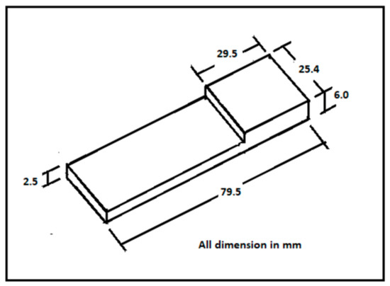
Figure 1.
Dimensions of steel and aluminium samples.
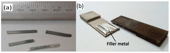
Figure 2.
Filler preparation: (a) filler metal; (b) filler metal arrangement in specimen.

Table 1.
Composition of Al-Si-Zn base filler metal (wt %).
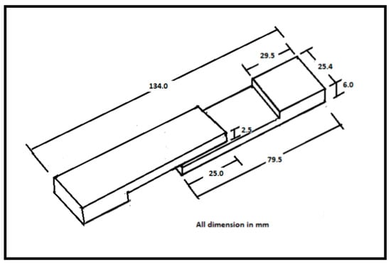
Figure 3.
Arrangement of both alloys for the joining process.
The torch-brazing process involved the burning of butane gas, whereby the base metal was heated to a temperature within a range where the bonding phase between the molten filler metal and the base metal could occur (see Figure 4a). A typical specimen produced from the brazing process is shown in Figure 4b. The brazing was conducted for three different torch durations of 1, 2, and 5 min respectively, to see the effect of different holding times and temperatures on surface wetting by the filler.
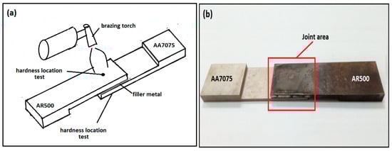
Figure 4.
Brazing process: (a) the schematic of the torch-brazing setup and hardness location test; (b) an example of a typical specimen produced.
The joint strength was evaluated by shear testing (3 tests for each flame time). Shear tests were carried out using a universal testing machine (model Zwick Roell Z100, Zwick Roell, Ulm, Germany) with a load cell 100 kN and performed at a constant cross-head speed of 1.5 mm/min. The profile (cross-section) of the brazed joint was observed by using a variable pressure scanning electron microscope (VP-SEM) (model Zeiss Evo Ma 10, Carl Zeiss, Oberkochen, Germany), while the surfaces fractures were observed by using a stereo microscope (model Olympus SZ61, Olympus Corporation, Tokyo, Japan). The hardness test was conducted by using a Rockwell Brinell machine (model Shimadzu DXT, Shimadzu. Corp., Kyoto, Japan) applying a scale B steel ball diameter of 1/16 inches and a load of 100 kgf. The hardness values of the base metals were taken on the free surfaces (as shown in Figure 4a), while those for the brazing seam were taken on the filler on the fractured surfaces. The hardness of the brazing seam (filler metal after brazing) was taken to study its influence on the joint.
3. Result and Discussion
3.1. Intermetallic Compound Layer
The presence of an IMC layer is known to affect the crack sensitivity, ductility, and strength of a joint. A thicker layer of IMC results in more brittle joints and reduces strength and hardness [32]. A previous work had also shown that the thickness of the IMC layer increases with the increase in the brazing time and temperature [33]. In this work, the thickness of the IMC was observed for both the AR500 steel/filler metal and the AA7075 aluminium alloy/filler metal. Figure 5 shows the thickness of the IMCs formed on AR500 and AA7075 with filler metal for three different flame times (1, 2, and 5 min). The brazing temperature was recorded by a thermocouple for the flame times of 1, 2, and 5 min. For consistency, the brazing temperature recorded was based on the temperature of the AR500 alloy (the thermocouple was positioned on the bottom surface as shown in Figure 6). The values of temperature recorded are shown in Figure 5.
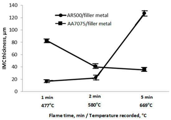
Figure 5.
Effect of flame time and temperature on thickness of intermetallic compound (IMC) layer formed on AR500 steel and AA7075 aluminium alloy.
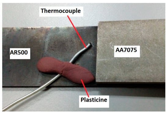
Figure 6.
Location of thermocouple during brazing process.
The thickness of the IMC layers as summarised in Figure 5 can be visualised using the SEM micrographs shown in Figure 7, Figure 8 and Figure 9. These results indicated that the thickness of the IMC layers formed between the AR500 steel and the filler metal increased substantially with increasing flame time, while those (the IMC layers) formed between the AA7075 and the filler showed a decrease with increasing flame time.
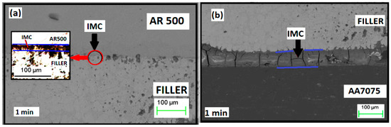
Figure 7.
(a) IMC layer between AR500 and filler and (b) IMC layer between AA7075 and filler, for flame time of 1 min.
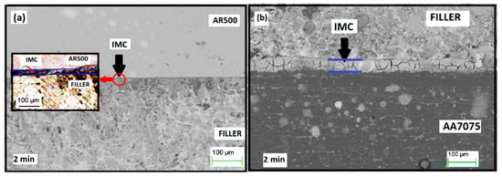
Figure 8.
(a) IMC layer between AR500 and filler and (b) IMC layer between AA7075 and filler, for flame time of 2 min.
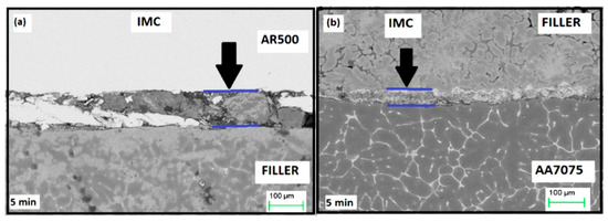
Figure 9.
(a) IMC layer between AR500 and filler and (b) IMC layer between AA7075 and filler, for flame time of 5 min.
The results of the energy dispersive X-ray (EDX) analysis for flame times of 1 and 5 min are shown in Figure 10 and Figure 11, respectively. They show that at 1-min flame time, the reaction layer or the IMC formed on the AR500/filler consisted of an AlZnO compound, whereas on the AA7075/filler metal, the IMC consisted of an FeAlZnO compound. These similar observations were seen for the 2-min flame time samples, hence the EDX results were not shown here. However, when the flame time was increased to 5 min, the IMCs formed were primarily composed of the Fe-rich compounds. The layers between AR500 and the filler were found to be enriched in the FeAl compounds, while those between AA7075 and the filler were enriched in the Fe3Al compounds. It should be mentioned that only the relative compositions of Al and Fe were evaluated in the present investigation, based on atomic percentage from the EDX results [34,35]. These are shown in Table 2. EDX analysis was carried out at various spots and around the interface layer (some typical spots are shown in Figure 10a). The different elemental ratios indicate the presence of different IMCs in this region.
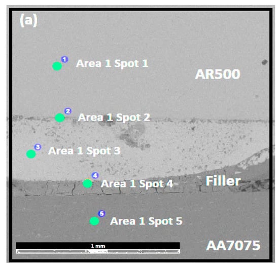
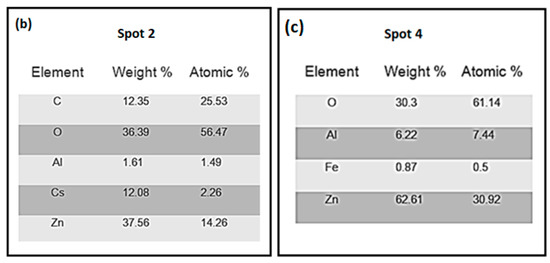
Figure 10.
Energy dispersive X-ray (EDX) analysis of torch-brazed joint between AR500 steel and AA7075 aluminium alloy for flame time of 1 min: (a) SEM image of spot areas; (b) analysis of spot area 2 (IMC of AR500/filler); and (c) analysis of spot area 4 (IMC of AA7075/filler). Adapted from [36], with permission from Institut Pengurusan Penyelidikan (RMI), Universiti Teknologi MARA, 2017.
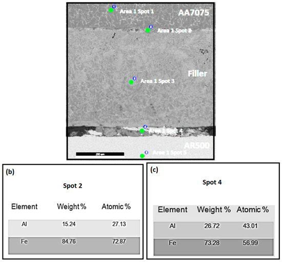
Figure 11.
EDX analysis of torch-brazed joint between AR500 steel and AA7075 aluminium alloy for flame time of 5 min: (a) SEM image of spot areas; (b) analysis of spot area 2 (IMC of AA7075/filler), and (c) analysis of spot area 4 (IMC of AR500/filler).
Table 2.
SEM–EDX analysis results on FeAl compound of torch-brazed joint between AR500 steel and AA7075 aluminium alloy for flame time of 5 min.
3.2. Mechanical Properties
Nippon Steel conducted a study on the strength of steel and aluminium joints for automotive body parts that were made by using various methods of joining, such as spot welding, self-piercing riveting, blind riveting, friction stir welding, adhesive bonding, and laser brazing, and reported that the highest shear load that could be achieved was less than 6000 N [37]. Figure 12 shows the average shear load (of three tests) of the brazed joint produced in the current study by using Al–Si–Zn filler metal. From the figure, it can be seen that a shear strength was achieved in the range of 1340–6460 N. The results show that the shear load decreased with increasing flame time and temperature. For the joint formed by brazing for 2 and 5 min of flame time, the joint shear load decreased significantly compared to that produced by the 1-min flame time. The poor shear strength of the joints produced by the 2-min and 5-min flame times was due to the increased thickness of IMCs and formation of Fe–Al IMCs in the interfaces (AR500/filler or AA7075/filler). The lower strengths were also influenced by the formation of oxide layers caused by increasing brazing temperature as the process was carried out in an uncontrolled atmosphere. The effect of oxide layers on the joint strength is further discussed in Section 3.3.
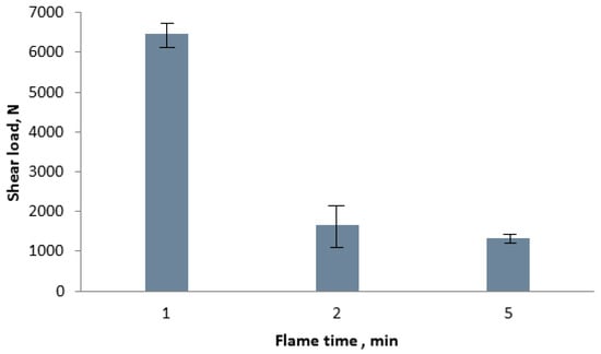
Figure 12.
Shear load vs flame time for torch brazing of joint between AR500 steel and AA7075 aluminium alloy.
The hardness of AR500 steel, AA7075 aluminium alloy, and filler metal (brazing seam) after brazing was also investigated in this study. Figure 13 shows the hardness of base metals before and after brazing, while the hardness of filler metal (after brazing process) is shown in Figure 14 (average hardness values of 6 readings for base metals and filler). The results showed that the hardness of both base metals after brazing had decreased. The hardness of AR500 and AA7075 decreased at 1 and 2 min of flame time. The recorded temperatures during those flame times were 477 °C and 580 °C. Even though the temperatures were recorded on the AR500 surface (see Figure 5), the temperatures on the AA7075 should be around the same values. These high temperatures essentially had given an annealing experience to the aluminium base metal, resulting in the formation of coarse grains of the MgZn2 phase that were nonuniformly distributed in the matrix, hence reducing the hardness of the AA7075, as also discussed by Isadare et al. [38]. However, at 5 min of flame time, the hardness of the aluminium alloy had increased and the temperature recorded for that flame time was 669 °C. This temperature is above the solvus temperature of the aluminium alloy that might result in the formation of fine, uniformly dispersed precipitates of the MgZn2 phase in the aluminium matrix. As further discussed by Isadare et al., these precipitates could serve as inclusions in the lattice of the host crystals in the solid solutions, and therefore might have given more lattice distortions to the alloy, making it stronger and harder [38].
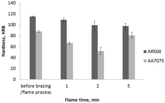
Figure 13.
Hardness vs flame time for AR500 and AA7075 specimen plates.
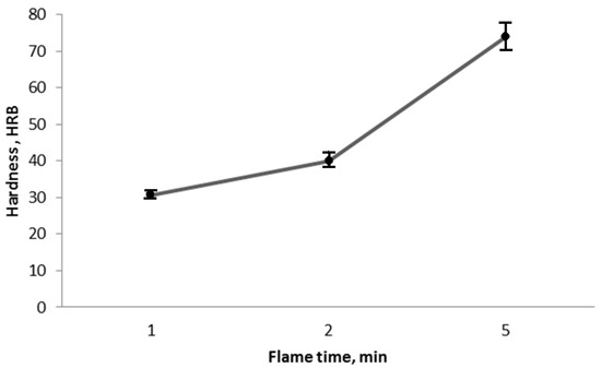
Figure 14.
Hardness vs flame time for brazing seam.
On the other hand, Figure 13 also shows that there was no significant change in the hardness of the AR500 steel base metal. Base on the Fe–C phase diagram, the temperature has an effect on the microstructure and properties of steel at around 738 °C (eutectoid temperature) [39]. The maximum temperature used in the brazing process in the current study was 669 °C and below the eutectoid temperature; therefore, no significant change in the hardness value of the steel took place. As for the brazing seam, the results in Figure 14 showed that its hardness had increased when the flame time and temperature were increased. This happened because of the solid solution strengthening effect in the filler metal during the flaming process, as mentioned by Dai et al. [40]. In this study, the low brazing seam hardness was related to the better joint strength, which was in agreement with the study by Suenger et al. They reported that the joint with a low-hardness or high-ductility brazing seam would improve the joining ability of the filler to the base metals [41].
3.3. Fracture Surface Observation
Figure 15 shows the stereo microscope images of the fractured surface of the brazed joint after the shear test. In all the joint specimens of AR500 steel and AA7075 aluminium alloy, the fractures occur in the bonding between the base metal and filler, where IMCs formed. The fractures caused by the shear test occurred in the joint interface between the AR500 and filler or AA7075 and filler, depending on the brazing temperature used. The images in Figure 15a,b of the joint fracture between AR500 steel and AA7075 aluminium alloy that occurred after flame times of 1 and 2 min show that the filler metal had detached from the AA7075 aluminium alloy base metal. The EDX analysis in Figure 10 shows that the IMC formed in the joint brazed for 1 min consisted of Zn-rich compounds. These compounds had lowered their joint strengths. This observation was in agreement with several earlier studies [42,43]. Here, the fracture for the 1- and 2-min flame times samples had occurred at the AA7075/filler interface due to the existence of these Zn-rich compounds.
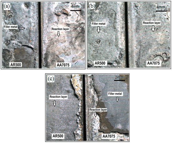
Figure 15.
Fracture surfaces of AR500 steel and AA7075 brazed joint for the flame times of (a) 1 min; (b) 2 min; and (c) 5 min. Adapted from [48], with permission from Penerbit UTM Press, 2016.
For the joint prepared under the condition of a 5-min flame time, the joint had fractured at the AR500/filler interface (see Figure 15c; the interface that is rich in FeAl, as also observed by previous other researchers) [14,15,44]. As mentioned in the EDX analysis above (Figure 11), these AA7075/filler and AR500/filler interfaces were rich in Fe3Al and FeAl compounds, respectively. Thus, the results showed that the Fe3Al-rich compounds on the AA7075/filler interface had given better bonding strength than that of the AR500/filler interface. This fracture behaviour that is dependent on the brazing temperature and time was also elaborated by Tashi et al. [45].
At the same time, it was observed that the dark reaction layers had formed on joint surfaces of both base metals. The coverage of these layers had increased with increasing flame times and temperatures. These layers were likely to be the oxide layers that formed during the heating or flame process, as also observed by Ikeuchi et al. [46]. The formation of an oxide reaction layer reduces the diffusion of the filler metal into the base metal and also reduces the strength of the joint [47].
4. Conclusions
In this study, the joining of AR500 steel and AA7075 aluminium alloy by using a simple torch-brazing technique was successfully carried out. The effect of brazing time was investigated and the results obtained can be summarized as follows:
(1) The study shows that in all cases presented, fractures will always occur at the metal/filler interface containing Zn-rich or FeAl intermetallic compounds. It signifies that the interface containing an IMC with a higher Fe ratio, e.g., Fe3Al, is stronger than the interface containing an IMC with a relatively lower Fe ratio, e.g., FeAl.
(2) The shear strength of the interface of the joint decreased with increasing flame or brazing temperature. The highest shear load was 6460 N, which was obtained at the brazing temperature of 477 °C.
(3) The hardness of the aluminium base metal had decreased at 1- and 2-min flame times (brazing below solvus temperature) due to the precipitation of coarse MgZn2 precipitates.
(4) The formation of oxide layers at the metal/filler interface could significantly affect the joint strength of the brazing.
Author Contributions
M.N.M. carried out the experimental works, analysis and writing under the supervision of M.Z.O., S.A. and Z.S., while M.F.A. and W.F.H.W.Z. provided guidance on the write-up.
Funding
This research was funded by Ministry of Higher Education Malaysia [LRGS/2013/UPNM-UKM/04].
Acknowledgments
The authors wish to express their gratitude to the Ministry of Higher Education Malaysia, Universiti Kebangsaan Malaysia, and Universiti Pertahanan Nasional Malaysia for the financial assistance and support.
Conflicts of Interest
The authors declare no conflict of interest.
References
- Salleh, M.S.; Omar, M.Z.; Alhawari, K.S.; Mohammed, M.N.; Mad Ali, M.A.; Mohamad, E. Microstructural evolution and mechanical properties of thixoformed A319 alloys containing variable amounts of magnesium. Trans. Nonferrous Met. Soc. China 2016, 26, 2029–2042. [Google Scholar] [CrossRef]
- Salleh, M.S.; Omar, M.Z. Influence of Cu content on microstructure and mechanical properties of thixoformed Al–Si–Cu–Mg alloys. Trans. Nonferrous Met. Soc. China 2016, 25, 3523–3538. [Google Scholar] [CrossRef]
- Salleh, M.S.; Omar, M.Z.; Syarif, J. The effects of Mg addition on the microstructure and mechanical properties of thixoformed Al–5%Si–Cu alloys. J. Alloys Compd. 2015, 621, 121–130. [Google Scholar] [CrossRef]
- Emel, T.; Jerry, E.G.; John, C.L. Dissimilar friction welding of 6061-T6 aluminum and AISI 1018 steel: Properties and microstructural characterization. Mater. Des. 2010, 31, 2305–2311. [Google Scholar]
- Choi, C.Y.; Kim, D.C.; Nam, D.G.; Kim, Y.D.; Park, Y.D. A hybrid joining technology for aluminum/zinc coated steels in vehicles. J. Mater. Sci. Technol. 2010, 26, 858–864. [Google Scholar] [CrossRef]
- Lee, C.-J.; Kim, J.-Y.; Lee, S.-K.; Ko, D.-C.; Kim, B.-M. Parametric study on mechanical clinching process for joining aluminum alloy and high-strength steel sheets. J. Mech. Sci. Technol. 2010, 24, 123–126. [Google Scholar]
- Rahman, N.A.; Abdullah, S.; Zamri, W.F.H.; Abdullah, M.F.; Omar, M.Z.; Sajuri, Z. Ballistic limit of high-strength steel and Al7075-T6 multi-layered plates under 7.62-mm armour piercing projectile impact. Latin Am. J. Solids Struct. 2016, 13, 1658–1676. [Google Scholar] [CrossRef]
- Kenji, M.; Shigeyuki, N.; Chika, S.; Hiroshi, S.; Akiro, H. Dissimilar joining of aluminum alloy and steel by resistance spot welding. SAE Int. J. Mater. Manf. 2009, 2, 58–67. [Google Scholar]
- Kim, K.; Lee, J.; Cho, H. Analysis of pulsed Nd:YAG laser welding of AISI 304 steel. J. Mech. Sci. Technol. 2010, 24, 2253–2259. [Google Scholar]
- Feng, J.-C.; He, P. High frequency induction contact reactive brazing of aluminum to stainless steel. Trans. Nonferrous Met. Soc. China 2005, 15, 11–15. [Google Scholar]
- Laik, A.; Shirzadi, A.A.; Tewari, R.; Anish, K.; Jayakumar, T.; Dey, G.K. Microstructure and interfacial reactions during active metal brazing of stainless steel to titanium. Metall. Mater. Trans. A 2013, 44, 2212–2225. [Google Scholar] [CrossRef]
- Dai, W.; Xue, S.; Lou, J.; Wang, S. Microstructure and properties of 6061 aluminum alloy brazing joint with Al–Si–Zn filler metal. Mater. Trans. 2012, 53, 1638–1643. [Google Scholar] [CrossRef]
- Chen, T.; Lin, W.B. Optimal FSW process parameters for interface and welded zone toughness of dissimilar aluminium–steel joint. Sci. Technol. Weld. Join. 2010, 15, 279–285. [Google Scholar] [CrossRef]
- Ogura, T.; Ueda, K.; Saito, Y.; Hirose, A. Nanoindentation measurement of interfacial reaction layers in 6000 series aluminum alloys and steel dissimilar metal joints with alloying elements. Mater. Trans. 2011, 52, 979–984. [Google Scholar] [CrossRef]
- Kimapong, K.; Watanabe, T. Lap joint of A5083 aluminum alloy and SS400 steel by friction stir welding. Mater. Trans. 2005, 46, 835–841. [Google Scholar] [CrossRef]
- Yamamoto, N.; Takahashi, M.; Ikuechi, K.; Aritosh, M. Interfacial layer in friction-bonded joint of low carbon steel to Al–Mg alloy (AA5083) and its influence on bond strength. Mater. Trans. 2004, 45, 296–299. [Google Scholar] [CrossRef]
- Yasuyama, M.; Ogawa, K.; Taka, T. Spot welding of aluminum and steel sheet with insert of aluminum clad steel sheet (1st report). J. Jpn. Weld. Soc. 1996, 14, 314–320. [Google Scholar] [CrossRef]
- Mathieu, A.; Pontevicci, S.; Viala, J.; Cicala, E.; Mattei, S.; Grevey, D. Laser brazing of a steel/aluminium assembly with hot filler wire (88% Al, 12% Si). Mater. Sci. Eng. A 2006, 435, 19–28. [Google Scholar] [CrossRef]
- Miyamoto, K.; Nakagawa, S.; Sugi, C.; Sakurai, H. Disimillar joining of aluminium alloy and steel by resistance spot welding. SAE Int. J. Mater. Manuf. 2009, 2, 58–67. [Google Scholar] [CrossRef]
- Khodir, S.A.; Shibayanagi, T. Microstructure and mechanical properties of friction stir welded dissimilar aluminum joints of AA2024-T3 and AA7075-T6. Mater. Trans. 2007, 48, 1928–1937. [Google Scholar] [CrossRef]
- Trimble, D.; Mitrogiannopoulos, H.; O’Donnell, G.E.; McFadden, S. Friction stir welding of AA2024-T3 plate–the influence of different pin types. Mech. Sci. 2015, 6, 51–55. [Google Scholar] [CrossRef]
- Rao, T.S.; Reddy, G.M.; Rao, S.R.K. Microstructure and mechanical properties of friction stir welded AA7075–T651 aluminum alloy thick plates. Trans. Nonferrous Met. Soc. China 2015, 25, 1770–1778. [Google Scholar] [CrossRef]
- Sepe, R.; Laiso, M.; De Luca, A.; Caputo, F. Evaluation of residual stresses in butt welded joint of dissimilar material by FEM. Key Eng. Mater. 2017, 754, 268–271. [Google Scholar] [CrossRef]
- Citarella, R.; Carlone, P.; Lepore, M.; Sepe, R. Hybrid technique to assess the fatigue performance of multiple cracked FSW joints. Eng. Fract. Mech. 2016, 162, 38–50. [Google Scholar] [CrossRef]
- Citarella, R.; Carlone, P.; Sepe, R.; Lepore, M. DBEM crack propagation in friction stir welded aluminum joints. Adv. Eng. Softw. 2016, 101, 50–59. [Google Scholar] [CrossRef]
- Carlone, P.; Citarella, R.; Sonne, M.R.; Hattel, J.H. Multiple crack growth prediction in AA2024-T3 friction stir welded joints, including manufacturing effects. Int. J. Fatigue 2016, 90, 69–77. [Google Scholar] [CrossRef]
- Carlone, P.; Citarella, R.; Lepore, M.; Palazzo, G.S. A FEM-DBEM investigation of the influence of process parameters on crack growth in aluminum friction stir welded butt joints. Int. J. Mater. Form. 2015, 8, 591–599. [Google Scholar] [CrossRef]
- Selamat, N.F.M.; Baghdadi, A.H.; Sajuri, Z.; Kokabi, A.H. Friction stir welding of similar and dissimilar aluminium alloys for automotive applications. Int. J. Automot. Mech. Eng. 2016, 13, 3401–3412. [Google Scholar] [CrossRef]
- Fellinger, J.; Citarella, R.; Giannella, V.; Lepore, M.; Sepe, R.; Czerwinski, M.; Herold, F.; Stadler, R. Overview of fatigue life assessment of baffles in Wendelstein 7-X. Fusion Eng. Des. 2018, in press. [Google Scholar] [CrossRef]
- Zhang, B.; Chen, G.; Zhang, C.; Ni, J. Structure and mechanical properties of aluminum alloy/Ag interlayer/steel non centered electron beam welded joints. Trans. Nonferrous Met. Soc. China 2011, 21, 2592–2596. [Google Scholar] [CrossRef]
- Liu, H.J.; Feng, J.C. Vacuum brazing TiAl-based alloy to 40Cr steel using Ag–Cu–Zn filler metal. J. Mater. Sci. Lett. 2002, 21, 9–10. [Google Scholar]
- Shah, L.H.; Akhtar, Z.; Ishak, M. Investigation of aluminium–stainless steel dissimilar weld quality using different filler metal. Int. J. Automot. Mech. Eng. 2013, 8, 1121–1131. [Google Scholar] [CrossRef]
- Wang, Q.; Leng, X.; Yang, T.; Yan, J. Effects of Fe–Al intermetallic compounds on interfacial bonding of clad materials. Trans. Nonferrous Met. Soc. China 2014, 24, 279–284. [Google Scholar] [CrossRef]
- Lee, K.J.; Kumai, S.J. Characterization of intermetallic compound layer formed at the weld interface of the defocused laser welded low carbon steel/6111 aluminum alloy lap joint. Mater. Trans. 2006, 47, 1178–1185. [Google Scholar] [CrossRef]
- Lee, K.-J.; Kumai, S.; Kawamura, N.; Ishikawa, N.; Furuya, K. Growth manner of intermetallic compounds at the weld interface of steel/aluminum alloy lap joint fabricated by a defocused laser beam. Mater. Trans. 2007, 48, 1396–1405. [Google Scholar]
- Muhamed, M.N.; Omar, M.Z.; Abdullah, S.; Sajuri, Z.; Zamri, W.F.H. The effect of surface texture on the joint shear strength of AR500 steel and AA7075. J. Mech. Eng. 2017, 4, 289–301. [Google Scholar]
- Sakiyama, T.; Murayama, G.; Naito, Y.; Saita, K.; Miyazaki, Y.; Oikawa, H.; Nose, T. Dissimilar metal joining technologies for steel sheet and aluminum alloy sheet in auto body. Nippon Steel Tech. Rep. 2013, 103, 91–98. [Google Scholar]
- Isadare, A.D.; Aremo, B.; Adeoye, M.O.; Olawale, O.J.; Shittuc, M.D. Effect of heat treatment on some mechanical properties of 7075 aluminium alloy. Mater. Res. 2013, 16, 190–194. [Google Scholar] [CrossRef]
- Okamoto, H. The C-Fe (Carbon-Iron) system. J. Phase Equilib. 1992, 13, 543–565. [Google Scholar] [CrossRef]
- Dai, W.; Xue, S.; Lou, J.; Wang, S. Torch brazing 3003 aluminum alloy with Zn–Al filler metal. Trans. Nonferrous Met. Soc. China 2012, 22, 30–35. [Google Scholar] [CrossRef]
- Suenger, S.; Kreissle, M.; Kahnert, M.; Zaeh, M.F. Influence of Process Temperature on Hardness of Friction Stir Welded High Strength Aluminum Alloys for Aerospace Applications. Procedia CIRP 2014, 24, 120–124. [Google Scholar] [CrossRef]
- Siahaan, E.; Soegijono, B.; Hikam, M. The effect of zinc composition in melting point and microstructure of lead-free solder. Int. J. Basic Appl. Sci. 2014, 14, 17–20. [Google Scholar]
- Hamada, N.; Uesugi, T.; Takigawa, Y.; Higashi, K. Effect of addition of small amount of zinc on microstructural evolution and thermal shock behavior in low-Ag Sn–Ag–Cu solder joints during thermal cycling. Mater. Trans. 2013, 54, 796–805. [Google Scholar] [CrossRef]
- Lee, K.-J.; Kumai, S.; Arai, T. Interfacial microstructure and strength of steel to aluminum alloy lap joints welded by a defocused laser beam. Mater. Trans. 2005, 46, 1847–1856. [Google Scholar]
- Tashi, R.S.; Mousavi, S.A.A.A.; Atabaki, M.M. Difussion brazing of Ti-6Al-4V and stainless steel 316L using AgCuZn filler metal. Metall. Mater. Eng. 2013, 19, 189–201. [Google Scholar]
- Ikeuchi, K.; Yamamoto, N.; Tkahashi, M.; Aritoshi, M. Effect of interfacial reaction layer on bonding strength of friction bonded joint of Al alloy to steel. Trans. JWRI 2005, 34, 1–10. [Google Scholar]
- Zaharinie, T.; Yusof, F.; Hamdi, M.; Ariga, T.; Moshwan, R. Effect of brazing temperature on the shear strength of Inconel 600 joint. Int. J. Adv. Manuf. Technol. 2014, 73, 1133–1140. [Google Scholar] [CrossRef]
- Muhamed, M.N.; Omar, M.Z.; Abdullah, S.; Sajuri, Z.; Zamri, W.F.H.; Rahman, M.A.I.A.; Abdullah, M.F. Investigation on brazing interface bonding characteristic of AA7075 and AA6061 aluminium alloy with AR500 steel using Al-Si-Zn filler metal. J. Teknol. 2016, 78, 129–135. [Google Scholar]
© 2018 by the authors. Licensee MDPI, Basel, Switzerland. This article is an open access article distributed under the terms and conditions of the Creative Commons Attribution (CC BY) license (http://creativecommons.org/licenses/by/4.0/).