Laser Hybrid Butt Welding of Large Thickness Naval Steel
by
 ,
,
Cristina Churiaque
1 ,
,
Mariane Chludzinski
1,
Manuel Porrua-Lara
2,
Antonio Dominguez-Abecia
2,
Francisco Abad-Fraga
2 and
Jose Maria Sánchez-Amaya
1,* 1
Department of Materials Science and Metallurgical Engineering and Inorganic Chemistry, LABCYP, Faculty of Engineering, University of Cádiz, Av, Universidad de Cádiz 10, E-11519 Puerto Real-Cádiz, Spain
2
Navantia S.A. Astillero Bahía de Cádiz, Polígono Astillero s/n, E-11519 Puerto Real-Cadiz, Spain
*
Author to whom correspondence should be addressed.
Metals 2019, 9(1), 100; https://doi.org/10.3390/met9010100
Submission received: 27 November 2018
/
Revised: 10 January 2019
/
Accepted: 14 January 2019
/
Published: 18 January 2019
(This article belongs to the Special Issue Laser Welding of Industrial Metal Alloys)
Abstract
:Plates joining is one of the first stage at large vessels manufacturing line, process conditioning the whole shipbuilding production. Laser Arc Hybrid Welding (LAHW) process is nowadays providing promising results for large thickness naval steel, being primarily used for welding plates with thicknesses between 6 to 15 mm, reaching up to 51 mm. In addition to this high penetration ability, LAHW allows increasing the production rates. Therefore, this technology is proposed as an alternative to conventional welding processes in shipbuilding, as it integrates the advantages of laser and arc welding, providing high process stability, high welding speed and penetration, narrow weld beads with a low heat input and good metallurgical properties. The present review reports the most representative investigation regarding the use of this technology to join large thickness flat panels of naval steel. It includes a summary of the most influential process variables, equipment characteristics, material properties, naval regulations, as well as microstructural characterisation and mechanical properties of joints. This review is thought to help readers from different backgrounds, covering from non-expert on welding or on naval sector, to industrial LAHW applicators and researchers. The industrial need of performing one single pass procedure to assure high quality welds of high thickness is suggested as one of the key aspects for future investigations.
1. Introduction
In the laser-arc hybrid welding process (LAHW), the laser beam and electric arc interact together in the weld pool and their synergistic effect is used to perform deeper and narrow welds (Figure 1), increasing the production rate [1,2]. Laser welding has gained popularity in recent years because laser beam focuses energy in a very small area [3]. The precision and concentration of energy provided by laser beam increases the welding speed, which in turn reduces the heat input and the thermal distortion in the welded parts [4]. However, most conventional laser systems do not have sufficient electrical efficiency for welding, besides being more expensive. Laser welding has little capacity for bridging or filling the gap and therefore requires great precision in the assembly of workpieces and preparation of edges [5]. In addition, the application of laser welding to highly reflective materials such as aluminium, copper, or gold is complex.
Contrary to the singularities of laser technology, arc welding processes have excellent gap filling capacity, high electrical efficiency and allow efficiently the welding materials with high reflectivity [6]. Arc welding systems are much cheaper than laser welding systems with similar capabilities [7]. However, the low energy density during arc welding makes the process slower, which induces a high heat input in the welding zone, resulting in thermal distortion of the welded part. Laser and arc processes when applied together in the same welding pool provide a hybridization effect that compensates the disadvantages of both processes and enhances its advantages [8].
At the end of the 1970s, Steen et al. [9] introduced the LAHW process. The results of his research clearly showed the advantages of combining a laser beam and an electric arc for welding. The hybridization effect of the plasma arc with a CO2 laser beam showed a remarkable increase in the welding speed (up to 100%), the weld depth (penetration) and the stability of the process [10]. After the demonstrated success of the application of this technique, the research and development of LAHW underwent a slow growth, due to the lack of availability of high power lasers.
The employment of a reliable laser source required a thorough knowledge of the process, which to that date was incomplete [11]. The development of high-power industrial lasers at the end of the 1980s [12] attracted the attention of researchers from the industrial sector and the academic world, who guided their studies towards improving the process to make it viable for industrial use.
By means of the hybridization, several disadvantages of the welding processes employed individually are minimised, including the problems of filling gap or the reflectivity of some alloys like aluminium. LAHW presented a greater development in the nineties due to the availability of CO2 lasers that could concentrate densities of higher powers, up to 106 W/cm2. Since then, several studies have been focused on materials approach applied on steel [10,13], titanium [14,15], aluminium alloys [16,17] or dissimilar joints [18,19]. Diverse investigations have been carried out to face different aspect of the process, as the economic viability of the laser-arc hybrid welding process, the influence of the relative position of the laser beam and the torch of the electric arc, edge preparation, minimization of metallurgical defects, optimization of process parameters, etc. [20,21,22,23]. However, despite the multiple advantages to the process, its industrial application was limited due to the high cost of the equipment and the complexity of the process, which requires a large number of adjustment parameters.
Another influential factor into the stagnation state of this technology was due to the lack of commercial availability of an integrated hybrid laser welding system. The first industrial system of LAHW was introduced in 2000 by the Fraunhofer Institute in Germany, for the manufacture of industrial tanks [24]. This system has been installed in different sectors, including: automotive industry, shipbuilding, pipe manufacturing, offshore structures, etc. At present, there are several LAHW systems commercially available [25,26,27,28], through partnership to develop LAHW systems between arc and laser companies [29]. The industrial applications of hybrid welding have grown in this century due to the advances of automation and control, as well as the tooling design. This progress has facilitated the development of integrated and commercial hybrid welding heads [7]. Among the companies and partnerships having had succeed in LAHW integration, the following can be cited: ESAB, Fronius, Lincoln Electric, IPG Photonics, Trumpf, Cloos or PEMA [25,26,27,28,29,30,31]. Currently, laser systems are becoming cheaper, more reliable and efficient and with higher power. Figure 2 graphically summarizes the evolution of the hybrid laser welding process since its introduction in the late 1970s.
1.1. Classification Societies and Standards
Shipbuilding is the area where a system of quality control first became necessary. Underwriters had a need to assess the risk in the insurance of a ship and its cargo; this was performed by registering the ships and classifying them according to the condition of their hull and the quality of the equipment. Such a system was first set up at Lloyd’s Coffee House in London and the register became Lloyd’s Register of Shipping, which was first published in 1760. Lloyd’s Register Office thus became the first Classification Society and was the model for similar organizations in other countries, such as American Bureau of Shipping, Bureau Veritas and Det Norske Veritas [32].
The society operated by appointing surveyors who inspected and classified the ships and by publishing an annual Register Book in which the classifications were recorded. Subsequently rules for ship construction were formulated and rules for steel ships were published in 1888. Surveyors were then appointed to inspect steelworks and test their products and Lloyd’s produced an Approved List of steelworks, which continues to this day. In 1920 an “electrically welded ship” was registered for the first time and in the following years Lloyd’s published a list of approved electrodes.
Originally, a single grade of steel was recognized for shipbuilding but following the loss of Liberty ships during and after the war, impact toughness tests were introduced. Then, in 1959 the International Society of Classification Societies developed unified requirements for ship steels which recognized five grades, lettered A to E. These grades became the basis for the specifications of individual societies. The scantlings of a ship (the section thickness of plate and stiffeners), are based on the minimum mechanical properties listed under the various steel grades [32,33,34].
Over the past sixty years of welding technology developments, the current expectation of weld quality has never been higher. Ensuring good quality welding plays an important role in all ship classification societies’ rules. Rules for shipbuilding are all written with the expectation of achieving safe shipping, including Lloyd’s Register [35], Det Norske Veritas, DNV [36], the American Bureau of Shipping [37] and also the International Association of Classification Societies, IACS [38]. The approach is similar for many safety critical construction applications, using qualified welders and welding procedures [39].
The increase of application of LAHW is also driving examination of what is an acceptable hybrid weld. DNV and Lloyd’s have already developed standards for hybrid welding for shipbuilding applications. However, with the recent activities for LAHW in other industries, there have been additional interest and need for the development of other standards and specifications by other organizations. The American Society of Mechanical Engineers (ASME) and the American Welding Society (AWS), both already having laser specifications, are active in the development of standards and recommended practices for hybrid processing. Specifications of both organizations are requested by companies using those specifications to develop their Procedure Qualification Records (PQR) and their Welding Procedure Specifications (WPS). These standards address the parameters needed to be documented and how much variation or change are allowed before approval of partially or fully re-qualified process [39].
The International Organization for Standardization (ISO) creates documents that provide requirements, specifications, guidelines or characteristics that can be used consistently to ensure that materials, products, processes and services are fit for their purpose [39]. The following Table 1 shows the ISO standards applicable to the LAHW process.
1.2. Welding in Shipbuilding
After the Second World War, welding replaced riveting in shipbuilding. This led to the adoption of prefabrication techniques, with the advantage of joining more quickly, also reducing the weight of steel, due to better design of the structural connections [40]. There is a great variety of electric arc welding processes employed in shipbuilding, as manual, semi-automatic and automatic. In addition, welding equipment has been configured to penetrate the full thickness of the joint and promote better deposition of filling material into the weld metal.
For example, the portable self-propelled welder consists of a carriage equipped with two welding heads which deposit a fillet weld simultaneously on both sides and can weld both sides of longitudinal stiffeners to steel plates. A similar welding equipment are used for joining flat panels of mild steel plating using an automatic arc welding with coated electrodes; the machine traverses the plate and the flux covered wire, which is fed continuously, giving the appropriate arc length. This procedure is used for welding outdoors, when the new construction is on its berth.
Another example of equipment is the Stud Welding Gun, which is generally used for the fastening of stud bolts to ensure insulation to bulkheads and the wood sheathing to decks. Gas Tungsten Arc Welding (GTAW) is mainly used for welding aluminium sheet or when the thickness of the plates is less than 6 mm. On the other hand, Electro Slag Welding (ESW) is used for welding cast sections and welding plates [40].
Shipbuilding was traditionally an open-air activity but in recent years much of the work has been transferred to indoor workshops where panels are welded using automatic processes, particularly submerged arc welding (SAW). Good improvements in productivity have been obtained by SAW at welding the fillets attaching a stiffener simultaneously. The use of robots, however, has been limited by the fact that many ships are a one-off design and also by the nature of the structure, which can incorporate a double curvature. Nevertheless, some progress has been made; for example, in welding of double bottoms. In many cases, this consist of numbers of rectangular boxes of similar design. A portal frame (Figure 3) makes possible the transfer of the robot from box to box. Within the box there are a number of weld patterns which are similar enough to allow macro programming of the robot [41].
Nowadays, leading companies of GMAW welding manufacture multi process equipment, frequently used in shipbuilding. Multi process equipment have a wide range of welding current, easy automation, high deposition rate and a wide range of materials to weld: steel, high strength steels, Al alloys. These modern welding power sources are equipped with special functions for arc control. These functions measure and adjust welding parameters during welding with minimum time delay so that the right parameters are set [43].
Welding is one of the most critical operations within ship construction. When welds fail, often the whole structure fails [44]. The most stringent precautions are required for welding of high strength quenched and tempered steels for naval vessels and particularly in submarines, where the plate thicknesses are generally larger. The first step in the control procedure is the qualification of welding consumables. They must meet the high tensile properties and also be subjected to the Pellini bulge test [32].
For the welding operation, it is necessary to establish control over the heat input rate. This is straightforward for SAW and for laying down stringer beads using a manual process. In vertical or overhead welding, however, a stringer bead technique increases the risk of lack of fusion defects or slag traps and weaving is necessary. Control of heat input rate is obtained by either limiting the thickness of weld deposit or by limiting the width of the weave in proportion to the core wire diameter. The seam inspection can be supported by radiography and/or ultrasonic testing. Surface inspection is carried out visually and using magnetic crack detection and dye penetrant testing [32].
1.3. LAHW in Shipbuilding
The LAHW stimulated the development of several studies with the objective of verifying the resulting characteristics of the process applied to different materials and industrial uses. Electric arc welding is the main process used in shipbuilding for joining structural steels [45]. However, the application of hybrid laser welding is becoming a promising alternative for the replacement of conventional and less productive processes in shipbuilding. The driving force of introduction of this technology in the building cruise ships and military vessels is the reduction of the thermal distortion generated by welding, which leads to a reduction in the corrective processes after welding, such as straightening/smoothing operations (whose costs are estimated at around 15–30% of the total staff costs in new constructions) [46].
An active use of the laser welding technologies applied to shipyards is performed by “Meyer-Werft” (Papenburg, Germany) company, which employs CO2-laser welding and LAHW at the productions of the cruise liner panel of 20 metres length. “Kvaerner Warnow Werft” (Rostock, Germany) company is equipped with a portal LAHW system with a fibre/disc laser. Fincantieri Shipyards (Monfalcone, Italy) and STX Finland Cruise Oy (Turku, Finland), are also equipped with laser and LAHW technologies for shipbuilding [47].
Currently, LAHW technology is facing new challenges and the application’s interest arises in building of large vessels. LAHW allows penetration depths in a single pass unreachable with other processes. The concise achievable penetration depends on the characteristics of the laser source used; LAHW usually allows welding relatively high plate thicknesses (in the order of 10 to 15 mm) [21]. Hybrid welding is proposed as ideal joining process for large-scale applications, such as those required in the building of chemical tankers, gas or oil tankers, since thickness of material to be welded is usually greater than 20 mm [48].
In a follow-up study, Mitsubishi Heavy Industries has recently used hybrid laser arc welding to reduce thermal deformation and improve the aesthetic appearance of a cruiser. The improvement in the finishing the hull of ships has made it possible to reduce the need to carry out additional finishing processes, such as cutting works on-site to adjust the distortion generated by the welding. The excellent surface finish of LAHW process has allowed increasing also the productivity [48].
The production of large scale welding requires heavy equipment. Trumpf has recently opened a facility in Austria, where a hybrid laser welding head from Fronius International is able to join sheets of up to 20 tons in weight, generating welds with 8 mm thickness [48].
Despite the technological and scientific advances mentioned above, it is necessary to clarify that hybrid laser welding is still under development for its definitive implementation in shipbuilding. There are still few shipyards that use laser technology in theirs welding production processes. In this regard, it is worth mentioning that there are numerous research lines aimed at the application of this technology to different industrial sectors, which includes not only shipbuilding (sector where its application is most evident) but also the aeronautical industry, offshore, railroad or nuclear industry. The European Union is aware of the possibilities offered by hybrid welding in the naval industry, so that currently there are numerous funded research projects trying to address different aspects of this technology for its full implementation in the industry [49,50,51,52].
2. Materials and Methods
2.1. Materials for Steel Naval Construction
There are several types and grades of naval steels, with different chemical composition and mechanical properties. These characteristics are essential to the selection of type of steel applied to different structures, according to the specific application requirements. Among them, the following can be mentioned: medium steel, high strength alloy and structural steel. In the same way, there are diverse types of filler wire, whose chemical composition and mechanical properties are oriented to different categories of steels.
2.1.1. Base Metal
The classification societies have their own rules for the design, construction and inspection of shipbuilding structures. Table 2 gives a summarized version of Lloyd´s requirements for ship steels for chemical composition and Table 3 displays the mechanical and impact properties required [53]. The key difference between the different grades relies on the temperature in which Charpy tests are performed. Grade A is general purpose mild steel for use in non-critical locations [32].
High strength steels are required for liquefied petroleum gas or methane carriers. There are basically two systems for the storage and transport of such materials. In the first one, the gas is maintained in liquid form at atmospheric pressure by refrigeration. In the second one, liquid is kept at atmospheric temperature under pressure. Similar systems may be used for transport of other gases [54].
High tensile quenched and tempered steels are also used in naval construction, particularly for aircraft carrier flight decks, side armour, magazine protection and the hulls of submarines. The first family of such steels was HY 80, which was developed after World War II in the USA. The composition was based on Krupp armour plate used for German Warships in World War I. It is a chromium-molybdenum-nickel steel of high yield strength and good notch-ductility [55]. The British submarines Valiant and Polaris were fabricated in HY 80; other warships used quenched and tempered armour plates to military industry.
HY 100, with a yield strength of 100 ksi (690 MPa), has a similar composition and is currently used as armour plate for US Naval vessels. Present interest lies in the development of hybrids between the Krupp type and microalloyed steel, where the total alloy content is reduced and the properties are maintained by a combination of thermomechanical processing and precipitation hardening. Table 4 compares the composition of the HY steels with more recent developments, designated as HSLA. Welding procedures for such materials are individually qualified and the technical specifications are defined. Other structural steels of interest for the joining by LAHW process are showed in Table 5. An example of this is the study carried out by Rethmeier [56], in which the base material selected was the typical pipeline steel API 5L X65.
2.1.2. Filler Wire
Frequently, in the HALW process, the laser is used to achieve the maximum penetration possible and the arc welding, for the incorporation of additional material that allows to cover the gaps and/or to modify the composition of the material in the welding zone [10,48]. In this sense, the contribution of a filling material is particularly advantageous for large scale applications.
The evidence of LAHW application to weld large scale great thickness plates can be clearly seen in some cases like the study of Agrawal [48], where a joint with 25 m length was performed. Thus, it is indicated that for the execution of such joint with autogenous laser process (without the use of filler material) it would be required to maintain a maximum separation of 0.3 mm along the entire joining zone (25 m), being in this case almost unfeasible from a practical point of view.
This problem is solved by using a hybrid system, which adds filler material to the melting pool by means of an electric arc, filling the weld holes during the joining process [48]. In this line, studies carried out in Reference [57] indicate that, using the parameters suitable for the hybrid process, the tolerance of the spacing between sheets can be increased by a factor of three or four, depending on the materials and equipment used, if compared with autogenous laser welding [57,58]. In Reference [46] it is indicated that the greater benefits of hybrid welding compared to autogenous laser welding is the increase in the tolerance of the spacing between workpieces, being able to execute a sound weld with spacing in the order of 1 mm [46].
2.2. Welding Processes Parameters
There is a large number of published studies concerning LAHW but not always all the welding parameters are specified. The quality of the joints obtained depends on the ratio of the power between the two sources of energy and also on the design parameters of the system. There are many welding parameter to define, as it is a combination of laser and arc processes. However, the main parameters can be grouped into design parameters (material thickness and gap geometry), combined process parameters (welding speed, process distance) and material parameters (type of material), as shown in Figure 4. These parameters significantly influence the process result [63]. A key experimental parameter is the relative position between the laser and arc sources, known as laser or arc leading. According to [64,65], the “Leading Arc” (Trailing Laser) configuration provides a deeper penetration, more stability to the arc process and lower the disturbances of the shielding gas, protecting better the arc. “Leading Arc” is also recommended for butt joint configurations without gaps, allowing also higher welding speeds. In this configuration, the arc produces a preheating effect in the joint to be welded that increases the temperature of the material and improves the absorption of the laser [64]. In contrast, “Leading Arc” configuration causes more spatters. On the other hand, “Leading Laser” (Trailing Arc) configuration provides more stability to the keyhole, increases the pool size at the upper part of the welding and improves the de-gassing effect, reducing the levels of porosity in the joint. It also allows a wider weld shape and smoother metallurgical transition between the weld and base metal. Besides, Leading Laser is better recommended for bigger welding gaps, presenting greater bridging capacity [65].
As mentioned above, hybrid welding is a combination of an arc welding and the laser welding in the same weld pool. Fundamental progress with regard to the development of combinations of various welding processes, that is, hybrid welding, is being experienced. The combination of arc metal welding with laser beam welding has been introduced into practice at a particularly quick speed (shipbuilding and automobile construction) and is reflected in the expectation of a higher degree of utilization in the industrial practice. Prior studies [49,50,59,60,61,62] have noted the importance of the fitting stage parameters. The combination results in very positive characteristics such as high energy density and low thermal load, high welding speed, deep penetration and high tensile strength, bridging capacity of gap and the possibility of the addition of filler metal and metal microstructure modification. It is possible to weld higher wall thicknesses in one pass, which gives considerable economic benefits [66]. A flow chart including the reported fitting stage parameters in LAHW is summarized in Figure 5 [67].
In LAHW, the laser provides the power density necessary to achieve high depth weld seams and high processing speeds [49]. On the one hand, the laser reduces the heat input and the distortion, while the arc process allows the filling of gap with the wire material [48], as can be seen in Figure 6.
In addition, the filling material provided by the arc welding also improves the profile of the weld to be convex instead of concave (Figure 7). The convex shape improves the mechanical properties of static resistance and life to fatigue [68]. In fact, a concave shape bead is considered a welding defect. The addition of filler material also involves changes in the chemical composition, microstructure and mechanical properties of the joint [61]. In this way, the quality of the welds can be improved, since the appearance of solidification cracks is avoided and the porosity in the welds is minimized [68,69]. The decrease in the appearance of cracks can be reached by changes in composition, microstructure and properties introduced by the filler material. The reduction of the porosity when using LAHW is associated to the fact that the fusion and subsequent solidification of the weld pool is slower than in autogenous laser welding. Consequently, the gas bubbles generated in the weld pool can escape more easily before solidification in the weld. The leading arc/leading laser configurations have also influence on this aspect of the process. Leading laser configuration is claimed to increase the size of the weld pool at the upper part of the welding zone, also reducing the porosity levels due to its de-gassing effect [64]. This slower cooling reduces the porosity content of the weld. However, in some materials, a slow welding thermal cycle may generate undesirable microstructure, associated with diminished properties of the joint [68].
Recently, Wahba et al. [62] experimented the combination of LAHW and cut-wire welding processes for joining thick steel plates (Figure 8). The grooved plate placed below the workpieces solved the problem of lack of metal deposition in the root. The cut-wire provided the homogeneity of the filler metal in all its depth providing a significantly greater uniformity in the joint, which substantially improved the deposition of filler material into the gap before welding. Based on this, plates up to 50 mm thick were welded using a double pass welding technique with no critical imperfections [61,68].
The introduction of laser technology in the shipbuilding industry is relatively recent, which involves technological uncertainties in the application of this new technology. Therefore, the development of specific welding and quality control procedures are required [70]. For example, in Reference [51] the procedures for the approval of CO2 laser welding for the naval industry are included. One of the problems associated with the use of laser welding is the increase in hardness and the decrease in toughness caused by the high cooling rate of the fusion pool. This problem is minimized with the use of hybrid welding, which involves lower cooling speeds and the controlled composition of filler metal [70]. Some studies with European funding have begun to examine the particular quality control and methods of non-destructive testing of laser welding in the shipbuilding industry [50,51,52].
2.2.1. Laser parameters
Table 8 shows a condensed values range of the laser parameters used in several experimental works of LAHW process, in order to have an approximation regarding the welding parameters already applied in literature [47,49,56,57,60,61,71,72,73]. The table reports welds involving thick plates of structural steel with an upper yield strength of 355 MPa and thickness between 20 and 45 mm. In addition, to prevent back reflections that can damage the optical fibre, a slight angle is applied to the laser source.
Several studies have postulated a convergence between the benefits of the application of LAHW process in terms of productivity. If conventional arc welding is compared with LAHW, the hybrid process is much faster and the heat input per unit length is much smaller. On one hand, the correlation between heat input and distortion is interesting because the thermal distortion also decreases in LAWH. On the other hand, the number of welding beads can be significantly reduced as well as the process time [68].
Kristensen [72] conducted a series of trials to join EH36 plates, obtaining satisfactory results. In this case study, a hybrid laser welding equipment of CO2 was used. Thick plates of 20 mm of thickness were welded in a single pass, while a multi passes technique was developed for higher thicknesses, reporting sound welds with a thickness of 25 mm in 3 passes.
The hybrid welding implementing laser technology is a relatively fast process, since the weld is obtained with a single laser scan. This effect produces a significant reduction of the generated distortion in workpieces [68,70].
LAHW is a faster process than conventional arc welding, since only one pass can be required to generate the weld bead in thicknesses below 25 mm. The laser can also promote a pre heat of the materials to be welded and as an automated heating process, the quality control is more efficient [63]. Bachmann M. et al. analyse the effect of pre-heating the welding zone of large thickness parts. This recent study concluded that the hardness decrease when the workpieces are preheating up to 160 °C [74].
2.2.2. Arc Parameters
The arc parameters such as current and voltage depend on filler wire feed rate. Variables significantly affect the stability of arc welding process and change the efficiency of LAHW process. The experimental values employed in several arc welding process tests taken from bibliography, are presented in Table 9.
It should be noted that there are different possible configurations in the disposition of the processes regarding the LAHW head. The relative arrangement of the arc and the laser beam axis (leading, trailing type, inclination and distance between laser and arc) depends on the material to be welded and its surface properties. Also important are the type of joint, edge preparation and welding position. Other factors having a strong influence on the design and equipment of the hybrid process are: the laser and arc power, the laser focussing parameters and the laser wavelength, the metal-transfer mode (MIG/MAG) and special boundary conditions and the accessibility for a seam tracking sensor [49]. Consequently, each experimental work has its own technical characteristics. Concerning the arc and laser relative position at the LAHW head, different possibilities have been analysed, as arc leading position (arc before laser) or laser leading (laser before arc). Specifically, in Reference [47,56,57,61,71] arc leading position is used; by contrast, Kristensen applied laser leading in Reference [72]; and both configurations (arc leading and laser leading) have been experimented in Reference [49,60,73].
A recent study by Cai et al. [75] optimized the design of the shielding gas nozzle for hybrid laser-MIG welding of thick section parts with a narrow gap configuration. A comparative study has been carried out on the transfer of metal droplets through the flow of shielding gas, proposing three designs of gas nozzles, where the appearance of the resulting weld beads was analysed. In addition, the shielding gas behaviour during the hybrid welding was investigated. Turbulence model was used to evaluate the turbulent kinetic energy of the flow and the dissipation rate, in each of the three nozzles. The best results were obtained with the square nozzle of the circular section (Figure 9c), whose behaviour in the transfer of the droplets of material was more stable and the number of porosities in the surface was reduced [73]. Figure 10 illustrates the experimental configuration of a LAHW equipment for welding thick plates with narrow joints.
2.3. Joint Design and Edge Preparation
The butt joining of large thickness steel performed with hybrid process delivers the benefits of both welding techniques. The laser process provides a high penetration depth and the arc process permits the joining of higher bridge gaps through the filling wire technique. The small spot diameter of the laser beam usually requires square edges, while the arc process involves the groove, principally for thick plates. These characteristics require a joint design different from the same used in the separated processes. Thus, the material edges must be prepared according to a combination of the configurations required by both techniques. This aspect is considered as advantage of the process as allows higher productivity in the welding, reduces the consumption of filler material and drops the distortions compared to a fully arc welded joint [76].
The joint design also varies according to the welding technique involved, that is, one or two welding sides in a single or multi passes. Despite the kind of design and the groove applied, the basic dimensions evaluated are: the gap (distance between workpieces), the height of the root face and angle of the arc. The grooves used in hybrid process usually display lower angle and narrower root height than arc processes.
Even though the hybrid laser process is not as sensitive to the configuration of the joints as the laser processes, the distance between the welded parts (air gaps) has a significant effect on productivity and quality [62,75,77,78]. The feasibility of the welding with different gaps was studied and it is experimentally demonstrated that is possible to weld plates with thickness up to 40 mm applying a maximum gap of 0.6 mm. As the gap increases and the angles became higher, a multi passes arc filling process technique becomes needed. With wider gaps, the application of backing method is required to support the molten metal. Wahba et al. [62] applied this technique using a square groove, consuming cut wire particles with the same chemical composition than the arc filler material. Joints with SM490A steel 25 and 50 mm thick were produced free of defects with a gap of 2.5 mm. An interesting result for industrial applications was observed by Farrokhi et al. [79]. Higher values of welding speed were achieved using zero gap and laser process for cutting the edge surfaces. As demonstrated, this method can enhance significantly the travel speed (130%) in comparison with common industrial milling procedure due to the rough surface produced.
Several studies were performed using different edge configurations. Figure 11 displays the groove designs of hybrid welding process adopted to thick materials. Table 10 reports the detailed description of LAHW configurations used to obtain full penetration joints. The groove type Y and its variation Double-Y (DY), are the most employed, providing the better combination of the characteristics of both processes. Y type is the most used groove type to weld up to 30 mm thick, using GMAW arc process coupled with a laser process (disk, fibre or CO2). Nevertheless, as the thickness ascends, the DY type is preferred to produce a sound joint.
3. Results
3.1. Joint Characterization
Hybrid joints of thick steel is still considered as a challenge. Several investigations have been developed using different techniques and experimental methods for the execution of these welds. All researches aim to develop welding procedures producing joints able to pass the industrial qualification processes and the approval required by standards. As a consequence, the investigations perform several evaluations to guarantee the quality of the joints, where the metallurgical characterisation and mechanical properties must be analysed. A number of studies examined the quality of butt joint in terms of macro and microstructure, tensile strength, hardness, impact toughness and fatigue, as followed.
3.2. Macrostructure
Diverse studies have been carried out to explore the influence of processes parameters (for both arc and laser sources), joint configurations and materials. The aim is to achieve sound welds with complete penetration and without critical imperfections. A minor number of studies were performed using specific shipbuilding steels, such as AH36 and other researchers used other steels applied in naval construction sector, such as high-strength low alloy (HSLA) steel. Table 11 summarised butt joints with complete and uniform penetration obtained with thickness of 25 to 51 mm.
A kind of hybrid technique consists on applying One Sided Single Pass welding (OS_SP), where one side of the plates are jointed with only one welding pass. Farrokhi et al. [80] welded 25 mm thick S355J2 steel with a tulip-shaped groove in a single pass using disk laser GMAW hybrid system with full penetration features (Table 11C). However, the laser cutting process applied to generate the groove was not completely reproducible and some experiments displayed partial penetration and cracks. The authors highlighted the importance of the groove geometry in the hybrid weld quality.
In some cases, the one sided single pass hybrid laser arc welding may be not enough to fill the gap between the workpieces or promote full weld penetration and additional arc passes are required after the hybrid root joint. In the same study cited above, Farrokhi et al. [80] used this one sided multi passes technique (OS_MP), applying two arc passes to achieve a full penetration (Table 11D). As an interesting result, the continuous solidification crack observed after the hybrid pass disappeared after the second arc pass, indicating that the crack could be re-melted and healed during the second process. Other investigation with thicker steel plates were developed by Rethmeier et al. [56] using one sided multi passes. Joints of API 5L X65 steel with 28 and 32 mm were welded using GMAW fibre laser hybrid process. In the thinner plates, the first layer hybrid welded was followed by one pass and the thicker plates need four layers (Table 11F,J). Zhang et al. [50] obtained a joint of 40 mm Q235 mild steel composed by 9 passes using fibre laser GMAW arc hybrid welding without visible macro defects (Table 11R).
In other conditions, the one sided welding method may not deliver sound joints with full weld penetration. Thus, in order to achieve the full penetration of thicker plates, the technique of double sided welding (both sides of the workpiece) were also investigated. Farrokhi et al. [79] have produced joints of 25 mm of S355J2 steel with a complete penetration using disk laser GMAW arc hybrid system in a double sided single pass (DS_SP) (Table 11B). This technique was also employed to produce other joint with 30 mm with RQT701 steel using GMAW and CO2 laser hybrid (Table 11G) [45]. Chen et al. [82] joined 30 mm thick high-strength steel with fibre laser arc hybrid welding. Double sided multi passes (DS_MP) technique was required to achieve a full penetration weld applying four layers. The first pass welding with two hybrid welding systems (double sided) was followed by the fillings welding with arc process in both sides (Table 11I). Bunaziv et al. [73] achieved the welding feasibility of 45 mm thick HSLA steel with high travel speeds (0.8 m/min). The joint was carried out using fibre laser GMAW hybrid process applying double sided welding technique (Table 11O). Nielsen et al. [76] showed the joining of 40 mm S355 J2+N structural steel using two types of GMAW laser hybrid techniques. One single sided hybrid welded was performed, followed by double sided GMAW arc process (Table 11S). In the other method explored, the hybrid process was applied in double sided of the plates (Table 11N). In both welds the complete penetration were accomplished.
Most of the studies were performed using GMAW power source. However, some investigations performed joints using submerged arc welding (SAW) in order to avoid gases porosities due to the higher heat input and the good thermal insulation of the slack and the flux with a molten pool longer and deeper, increasing the solidification cycle [69]. Reisgen et al. [83] performed joint of 35 mm API X65 steel using CO2 laser with SAW. The complete penetration without pores welds were executed with a double sided single pass technique (Table 11K). The study also developed other joints replacing the CO2 for disk laser, focusing in safety and reproducibility aspects, accomplishing good results. The same material with 35 mm were welded with negative and positive polarity (Table 11L,S) and P265GH steel joint with 40 mm were conducted (Table 11Q) as well as S460 plates with 51 mm (Table 11U). Wetzel et al. [59] used the SAW after the GMAW laser hybrid welding in order to fill the residual gap in a 40 mm thick joint. The S355 J2+N steel was laser hybrid GMAW arc welded in the root and backing passes, as a double sided process, followed by two passes in both sides using submerged arc (Table 11P).
Other method adopted with the SAW process is the use of a backing plate filled by cut wire particles. Wahba et al. [62] studied this method in SM490A steel, welding 25 mm thick in a single pass and plates of 50 mm in double pass. The joints did not display macrostructural imperfections (Table 11E,T).
Regarding to the laser type, predominantly the hybrid joints are carried out using disk or fibre laser. The CO2 laser joints were produced in AH36 and RQT701 steels in 25 and 30 mm thick (Table 11A,H). To execute the 25 mm joint with single sided welding, it was necessary to apply 3 passes, being required 5 passes to join the 30 mm thickness. In the RQT701 steel, a single pass in both sided with two GMAW power sources was need to weld 30 mm plate [49,72].
In summary, in order to guarantee a sound full penetrated joint of high thickness, most researches employed a multi passes technique. As the steel thickness enhances, the one sided technique is replaced by double sides welding procedure, with one or more layers applied. Up to 32 mm thick, most of the joints were welded using GMAW arc process with disk, fibre or CO2 laser source. The SAW process was also used to joint plates with more than 35 mm. The highest thick full penetration joints were obtained with 50 and 51 mm using this process, where the cut wire method was added in the 50 mm plate.
3.3. Joint Imperfections
The achievement of full penetration welding is essential to obtain a sound weld. The quality enhancement is accomplished with reduction or elimination of welding defects, being the most important challenges related to hybrid laser welding. The EN ISO 13919-1 [84] standard is commonly used to evaluate the quality levels in terms of imperfections for electron and laser beam weld, being the EN ISO 12932 [85] standard used for laser-arc hybrid welds. Similarly to occurring in laser process, the defects that usually appear in LAHW are pores, cracks and geometrical defects. The pores may be harmful to the joint and its presence is allowed under certain specification, although solidification cracks are usually forbidden due to the risk of failure during cyclic loading [49,76].
The imperfections can be associated to inadequate parameters processes (both laser and arc) or weld configuration. They can be visible from the weld surface weld, as observed by Cai et al. [75]. Different nozzles designs of arc torch were applied in 30 mm thick butt joints using fibre laser MIG hybrid welding and the straight-trapezium nozzle configuration displayed pores in a honeycomb distribution at the back weld surface (Figure 12a). The authors related this defect to the unstable droplet transfer and high velocity of the pure argon shielding gas. Another notable study was developed by Qinglong et al. [86], in which the effect of shielding gas on laser–MAG arc hybrid welding of thick high-tensile-strength steel plates is reported. The results concluded that the penetration depths of welds increased in hybrid welding with 100% CO2 gas and less porosity level appeared. However, the laser could not always penetrate the keyhole during the hybrid welding with mixed shielding gas (80% Ar–20% CO2) and more imperfections such as humping and spattering formation can appear.
If the defect is located inside the joint, destructive or non-destructive techniques can be used to detect it. The cross section of a 25 and 30 mm thick AH36 steel welded by Kristensen et al. [72] displayed imperfections in the second pass, although the pores were acceptable according EN ISO 13919-1 level C [84]. The joints performed by Farrokhi et al. [81] displayed full penetration but solidification cracks were observed (Figure 12b). The authors associated its presence due to the high travel speed applied (3.8 m/min), which lead to high cooling rates.
The appearance of the hybrid weld beads is very similar regardless of the type of joint configuration or laser and arc processes applied. Thick butt steel joints made by single sided hybrid arc laser processes exhibit a shape called as wine-cup, as occurred in other thickness and materials. This format represents the characteristics of the energy distribution of the processes in the molten pool, the laser being responsible for the narrowness zone and the arc process to the wider region [72]. In a single sided hybrid laser welding, the top part of the workpiece displays the fusion zone produced by the arc process, this region being recognized as the wider region. The middle and/or bottom (root layer) parts are narrow and consist of the fusion zone promoted mainly by the laser process. Both welding processes create also heat affected zones (HAZ); the higher heat input of the arc process makes the arc HAZ wider [62,87,88]. When double sides techniques are employed, this wine-cup feature may exhibit some variations.
3.4. Microstructure
The chemical composition of the steel and filler wire and, especially the carbon content, will significantly influence the resulting microstructure. Besides the features of the materials involved, the welding procedure will generate a significant modification in the metallurgical characteristics. The weld bead produce a thermal cycle to surrounding material and, in the case of a hybrid process, the two power sources impose different thermal cycles at the same time, especially in thick plates. Therefore, each weld zone develop different microstructures, associated to the cooling rates and travel speed.
In general, the microstructure generated by the laser zone is hard (bainite or martensite), composed of fine grains in the fusion zone (centre line), while the HAZ demonstrated restrain to the grain growth. On the other hand, the microstructure of the arc process may develop coarse grain in fusion zone with wider ferrite proportion in the HAZ [50,88,89]. Some studies reported the microstructural evolution of a complete penetration joint. Farrokhi et al. [80] investigated the case of single pass welding applied to 25 mm thick S355J2 steel using filler wire ESAB OK 12.50 and disk laser GMAW process (Table 11C,D). The microstructure of the laser zone was composed by bainite with columns bending towards the centre of the weld (Figure 13a). Acicular ferrite and bainite microstructures were obtained at the centreline of the weld, observing equiaxed dendritic structure in some areas, (Figure 13b). The effect of second arc pass after the hybrid process was observed only in the arc zone, as expected and acicular and proeutectoid ferrite microstructures were observed (Figure 13c).
Wahba et al. [62] studied the microstructure evolution developed in a 25 mm thick SM490A steel welded in a single pass using submerged arc filling process (Figure 14). Ferrite and pearlite banded microstructure is observed in the base material. Both arc and laser fusion zones mainly developed grain boundary ferrite and acicular ferrite microstructure, where the laser beam produced lower content of acicular ferrite and finer microstructure. The HAZ showed a transition feature from the welding region to the base material, where the coarse grains are turned into fine grains and then, a partially recrystallized microstructure.
Chen et al. [82] investigated the microstructure developed by double sided multi passes hybrid process applied to 30 mm high-strength steel. From the polygonal ferrite microstructure of the base metal steel, the hybrid process developed lath martensite microstructure in the laser and arc zones but in columnar grain structure only in the arc zone (Figure 15). The crystallographic assessment was performed using electron backscattering diffraction (EBSD) system and, as result of the hybrid process, a significantly reduction of the grain size was observed in the laser zone; the arc zone presented double grain size than the laser zone (Figure 16).
In thicker specimens, the effect of the arc process on the microstructure is more visible in multi-passes welding due to the successive layer deposition. In the case of nine layers applied in 40 mm Q235 mild steel (Table 11R), as investigate by Zhang et al. [50], the laser zone is reduced and displays acicular ferrite and dendrites columns growing from fusion line to weld centre. It was related to the narrower molten pool and faster cooling rate, which promoted the quick growth of columnar dendrites. The arc zone displayed the same structure but the dendrites had coarser grains size due to the higher heat input exposition and a higher content of acicular ferrite. As expected, the HAZ of laser and arc zones demonstrated coarse and fine grain region, exhibiting a Widmanstatten structure in the coarse region and fine pearlite and ferrite in the fine region (Figure 17).
3.5. Mechanical Properties
The mechanical properties of a joint are influenced by microstructure promoted during the welding, thus the same characteristics described above for the microstructure are applied. The arc and laser zones displays distinguish features and, when multi layers are required to fill the joint gap of thick joints, the characteristics of the arc process play an important role. The published investigations have reported the mechanical properties in terms of tensile strength, microhardness, Charpy and fatigue tests of complete penetration hybrid laser joints of thick steel plates, as followed.
3.5.1. Tensile Strength
The modification promoted by the hybrid process on the tensile strength provide sound outcomes, independently of the quantity of layers and technique applied. Chen et al. [82] joined 30 mm thick high-strength steel with four passes in double sided configurations. In the tensile tests performed at −50 °C the welded metal demonstrated higher strength than the base material, associated to the fine lath martensite developed. The weld zones displayed similar behaviour, where the laser zone displayed a slightly higher value than the arc zone, linked to the smaller grain size. In thicker joints studied by Zhang et al. [50], the tensile strength of Q235 mild steel with 40 mm joined with 9 layers indicated also better values than the base material (158%). Besides, the arc zone exhibited values 14.7% higher than the laser zone, maybe due to the lowest content of acicular ferrite microstructure.
In addition, the application of cut-wire technique also produces high strength joints, as demonstrated by Wahba et al. [62]. The tensile test specimens extracted from laser and arc zones of 25 mm thick SM490A steel joint indicated a higher strength of the joint, as the fracture occurred at the base material.
3.5.2. Hardness
As each weld zone originated by the welding process develops different microstructures, the microhardness measurements exhibit a heterogeneous profile, according to which process is dominant in each region. In order to reveal the influence of both joint process, profiles are preferably performed in horizontal and vertical lines, measuring the whole weld depth. Generally, the microhardness of both the arc and laser zones, as well the respective HAZs, are higher than the base material. For industrial applications, harder microstructures must be avoided during the welding in order to prevent the development of cracking mechanisms during service life. Therefore, relevant standards set a maximum limit of 350 HV [88].
The horizontal profiles measured in Reference [62] for 25 mm SM490A steel welded with a single pass demonstrated a progressively enhance of the values in the all welding regions. From the value of 138 HV of the base material, the laser zone of weld centre displayed higher hardness values (average of 253 HV) than arc zone (average of 224 HV), associated to the finer microstructure exhibited. The HAZ of laser zone demonstrated a peak in the profile in 306 HV. The same feature was demonstrated in 25 mm AH36 steel joint [49], where the horizontal profiles showed the effect of the passes on the microhardness. The base material exhibited 140 HV5 and the arc zone of the last pass (third) displayed the highest profile (peak above of 280 HV5). The laser (root) and arc zone of the second layer displayed similar peak values; however, the arc zone exhibited a wider welding region. The profile of the weld centre (vertical line) indicated a reduction of more than 100 HV5 in the overlapped processes zones.
In order to analyse the hardness evolution developed in thick joint welded with multi passes, the measurements have to be performed in different weld locations. In the 45 mm Q235 mild steel joint welded by Zhang et al. [50], different horizontal microhardness profiles were reported for the layers joint (Figure 18). In the centre of the weld, the laser zone (root) displayed higher values (above 280 HV0.2). This characteristic was associated to the rapid cooling rate and the microstructure composed by the finest grains. Meanwhile, the arc zones, composed by other 8 layers, displayed lower values due to the coarser grains and the mainly presence of ferrite. The HAZ of these regions displayed an improvement of the hardness related to the Widmanstatten structure.
3.5.3. Impact Toughness
As a technique applied to evaluate the impact toughness properties, the Charpy test is widely applied in industry for analysing the steel joints. Similarly to other properties, it is necessary to examine each welding region to define the effect of the welding processes. This test is essential to guarantee the joint quality, as there is always risk of martensite formation in laser welding fusion zone which can lead to impact toughness drop.
Impact tests were performed at −20 °C in the single pass joint of 25 mm SM490A and the specimens were extracted from the top and bottom parts of the joints, representing the laser and arc zones [62]. The arc zone performed with GMAW displayed higher values than the laser zone, 147 and 105 J, respectively. Even though these values were smaller than base material (195 J), they are above the minimum required by the industrial standard.
In order to evaluate the energy absorbed in a Charpy test by a nine layers joint, the specimens were extracted from upper, middle and lower parts in the weld centre and in the HAZs [62]. The results demonstrated the better outcomes obtained in all welding zones in comparison with the base materials, with an increase ranging from 32 to 60%. Regarding to the weld regions, it was observed a reduction of the values towards the lower part (laser zone) in the weld centre and HAZ, as the content of acicular ferrite decreased.
The evaluation performed by Wetzel et al. [59] indicated that the GMAW laser hybrid process followed by submerged arc filling welding applied to 40 mm S355 J2+N steel developed higher impact toughness. The values tested at −20 °C in the arc and laser zones were 68 and 64 J, respectively, displaying an increase from the base material (51 J). The HAZ of the laser zone exhibited 35 J, lower value than the base material.
The tests performed by Chen et al. [82] in a 30 mm high-strength steel joint using four passes in double sided configurations showed distinct results. Several experiments were carried out from −60 to 0 °C and the weld zone did not exceed the base material values. The authors associated this behaviour to the tougher microstructure of the steel (polygonal ferrites) and lath martensite of the welding zones. The laser zone showed higher values due to the higher content of grain boundaries with high disorientation angles. Nevertheless, all values obtained were above the relevant standard, regardless of the welding zone.
3.6. Fatigue
The fatigue behaviour is an important issue for any joint, especially for all cyclic loaded welded structures used any industrial application, such as ships and offshore structures. In thick steel hybrid joint, the concern must be even higher due to the inhomogeneous characteristics developed during the welding. Even with the initial stage of investigations involving this subject, the results are suggesting good fatigue performance promoted by the hybrid process. Joints of 25 mm thick EH36 steel tested under four-point bend loading indicated sound fatigue behaviour [49]. The measured S-N curves was higher than the IIW structural stress design curve FAT100 (International Institute of Welding terminology for fatigue strength of 100 MPa at 2 × 10⁶ cycles), even with the solidifications cracks observed at the weld centre prior to the fatigue tests. Other evaluation was performed by Wetzel et al. [59] using a double sided hybrid technique followed by submerged arc. The fatigue strength analyses of the 40 mm thick S355 J2+N steel indicated that the hybrid process provided better performance than joints welded only with submerged arc process. The author related the results to the reduced stress concentration of the flatter weld transition. Up to date, there are only few studies related to fatigue characteristics applied to hybrid joint of thick steel. Given the high importance of the fatigue behaviour in shipbuilding, future investigation should focus on performing dynamic tests on hybrid welds.
4. Conclusions
In shipbuilding industry, welding is considered the most critical operation. Until now, the electric arc welding has been used as the main process applied for joining structural steels. Nevertheless, the consolidation of the use of LAHW in thicker materials allows it to become a promising alternative for the replacement of conventional processes in shipbuilding. The hybridization compensates the disadvantages of both processes and enhances its advantages, promoting higher productivity. It is a stable process providing high weld quality and has the possibility of being integrated in an automated production line, reducing the costs associated. Such characteristics are needed in the shipbuilding industry and they are the driving force for the introduction of this technology in this sector.
In this regard, numerous researches have been performed with the aim of applying this technology to different industrial sectors, which includes not only shipbuilding. The feasibility of hybrid welding in thick material with different arc and laser processes was accomplished. Full penetration welds were obtained in different grades of steels with 25 to 51 mm thickness. The main arc process applied in the investigations are GMAW, although some few studies use SAW process. Disk and fibre lasers are the predominant laser sources in LAHW. Different joint configurations and welding procedures are reported. Regarding to the joint designs, different edge configurations have been investigated, being the Y and DY groove the most applied. Plates with up to 40 mm were performed with a maximum gap of 0.6 mm. Thicker materials (around 50 mm) can also be joint with square edge and 2.5 mm gap associated to cut wire technique to the hybrid process.
A complete metallurgical characterisation and a comprehensive batch of mechanical tests are essential and extremely important to guarantee the acceptable properties of the joints for its industrial application. The overall analysis regarding metallurgical and mechanical behaviour demonstrated that arc and laser sources provokes distinct thermal cycles; while the laser source generated a concentrated heat input with rapid cooling rates, the arc source promoted a wider weld bead with slower cooling rates.
Different combinations of LAHW process were applied to achieve butt joints with complete penetration and without critical imperfections. Those joints demonstrated, as expected in thick materials, the difference between the microstructures developed by each type of welding processes, according to the steel employed. In general, the laser process inputs a rapid thermal cycle that generates finer and harder microstructure in the fusion zone than the arc process. The HAZ promoted by the arc source displays a higher extension, which is associated to the technique involved; and these modifications defined the mechanical properties. As a consequence, the microhardness shows a heterogeneous profile, where the FZ and HAZ demonstrated values significantly higher than the base material but below the limits required by the relevant standards.
Regarding to tensile strength, the hybrid joints demonstrated sound results, independently of the quantity of layers and technique applied. At the moment, there is no consensus about tendencies of the impact toughness of the LAHW joints. As the thickness enhances, the welding procedure changes as well, modifying the heat input and the cooling rate imposed. Some studies indicated satisfactory results of the hybrid joint, where the fusion zones displayed higher values than the base material. Other researches exhibited values of the welding zone lower in comparison with base material. As a positive aspect, even with few studies oriented to the fatigue strength analyses, the results indicated that the hybrid process provided acceptable performance.
Despite the technological and scientific advances already accomplished, efforts must continue in order to achieve a higher degree of industrial application, specially shipbuilding or offshore structures. The researches have demonstrated the advantages of the LAHW and promising results in terms of feasibility of the process and joint quality. Joints were performed with high welding speed and suitable fit-up tolerance, showing deep penetration and high tensile strength and fatigue strength. However, at the present stage, the majority of researches applies a multi passes or double sided welding technique with excellent outcomes. From the industrial point of view, the joining process should be executed in a quickly and simple procedure in order to maximize the economic benefits in an automated production line. Therefore, future research is needed to improve the LAHW technology in order to be able to weld thick plates in a single pass. The investigations should also be focussed on the mechanical properties evaluation, reaching a complete analyses of the effect of the hybrid process into high thickness material.
Author Contributions
The present work is part of the PhD developed by C.C., C.C. has mainly worked on the analysis of relevant bibliography, historical evolution, materials involved and welding procedures of LAHW process. She also discussed the whole reviewed data. M.C. focusses her work on the description of joint configurations, metallographic characterisation and mechanical properties. M.P.-L. revised the welding procedure and base material properties. A.D.-A., Navantia supervisor of the PhD, revised the whole paper. F.A.-F., Navantia responsible of UIC program, revised the paper. J.M.S.-A., UCA supervisor of the PhD, planned the whole revision work, analysed and discussed the reviewed methodology and results and finally revised and edited the paper.
Funding
This research was funded by the Industrial PhD program of the UNIVERSITY OF CÁDIZ (UCA), and by the JOINT INNOVATION UNIT (UNIDAD DE INNOVACIÓN CONJUNTA, UIC) between UCA and NAVANTIA S.A.
Conflicts of Interest
The authors declare no conflict of interest.
References
- Zhang, S.; Shen, Y.; Qiu, H. The technology and welding joint properties of hybrid laser-TIG welding on thick plate. Opt. Laser Technol. 2013, 48, 381–388. [Google Scholar] [CrossRef]
- Atabaki, M.M.; Nikodinovski, M.; Chenier, P.; Ma, J.; Liu, W.; Kovacevic, R. Experimental and numerical investigations of hybrid laser arc welding of aluminum alloys in the thick T-joint configuration. Opt. Laser Technol. 2014, 59, 68–92. [Google Scholar] [CrossRef]
- Cui, L.; Chen, B.; Qian, W.; He, D.; Chen, L. Microstructures and Mechanical Properties of Dissimilar Al/Steel Butt Joints Produced by Autogenous Laser Keyhole Welding. Metals 2017, 7, 492. [Google Scholar] [CrossRef]
- Steen, W.M.; Mazumder, J. Laser Material Processing, 4th ed.; Springer: London, UK; Dordrecht, The Netherlands; Berlin/Heidelberg, Germany; New York, NY, USA, 2010; Volume 4, pp. 216–218. [Google Scholar] [CrossRef]
- Unt, A.; Poutiainen, I.; Grünenwald, S.; Sokolov, M.; Salminen, A. High Power Fiber Laser Welding of Single Sided T-Joint on Shipbuilding Steel with Different Processing Setups. Appl. Sci. 2017, 7, 1276. [Google Scholar] [CrossRef]
- Guen, E.L.; Fabbro, R.; Carin, M.; Coste, F.; Masson, P.L. Analysis of hybrid Nd:Yag laser-MAG arc welding processes. Opt. Laser Technol. 2011, 43, 1155–1166. [Google Scholar] [CrossRef] [Green Version]
- Ishide, S.; Watanabe, M. Latest MIG, TIG, arc-YAG laser hybrid welding systems for various welding products. In Proceedings of the International Symposium on High-Power Laser Macroprocessing, Osaka, Japan, 27–31 May 2002; pp. 347–352. [Google Scholar]
- Ascari, A.; Fortunato, A.; Orazi, L.; Campana, G. The influence of process parameters on porosity formation in Hybrid LASER-GMA welding of AA6082 aluminium ally. Opt. Laser Technol. 2012, 44, 1485–1490. [Google Scholar] [CrossRef]
- Steen, W.M.; Eboo, M.; Clarke, J. Arc augmented laser welding. In Proceedings of the 4th International Conference on Advantages in Welding Processes, Harrogate, UK, 9–11 May 1978; Volume 1, pp. 257–265. [Google Scholar]
- Górka, J.; Stano, S. Microstructure and Properties of Hybrid Laser Arc Welded Joints (Laser Beam-MAG) in Thermo-Mechanical Control Processed S700MC Steel. Metals 2018, 8, 132. [Google Scholar] [CrossRef]
- Ready, J.F. Industrial Applications of Lasers, 2nd ed.; Academic Press: London, UK, 1997. [Google Scholar]
- Seyffarth, P.; Krivtusun, I.V. Laser-arc Processes and Their Applications in Welding and Material Treatment; Taylor & Francis: London, UK, 2002. [Google Scholar]
- Turichin, G.; Kuznetsov, M.; Klimova-Korsmik, O.; Sklyar, M.; Zhitenev, A.; Kurakin, A.; Pozdnyakov, A. Laser-Arc hybrid welding perspective ultra-high strength steels: Influence of the chemical composition of weld metal on microstructure and mechanical properties. Procedia CIRP 2018, 74, 752–756. [Google Scholar] [CrossRef]
- Shi, J.; Zhou, Y.; Liu, L. Application of Pulsed Laser-TIG Hybrid Heat Source in Root Welding of Thick Plate Titanium Alloys. Appl. Sci. 2017, 7, 527. [Google Scholar] [Green Version]
- Li, C.; Muneharua, K.; Takao, S.; Kouji, H. Fiber laser-GMA hybrid welding of commercially pure titanium. Mater. Des. 2009, 30, 109–114. [Google Scholar] [CrossRef]
- Casalino, G.; Campanelli, S.L.; Dal Maso, U.; Ludovico, A.D. Arc leading versus laser leading in the hybrid welding of aluminium alloy using a fiber laser. Procedia CIRP 2013, 12, 151–156. [Google Scholar] [CrossRef]
- Huang, L.; Wu, D.; Hua, X.; Liu, S.; Jiang, Z.; Li, F.; Wang, H.; Shi, S. Effect of the welding direction on the microstructural characterization in fiber laser-GMAW hybrid welding of 5083 aluminum alloy. J. Manuf. Process. 2018, 31, 514–522. [Google Scholar] [CrossRef]
- Casalino, G.; Leo, P.; Mortello, M.; Perulli, P.; Varone, A. Effects of Laser Offset and Hybrid Welding on Microstructure and IMC in Fe–Al Dissimilar Welding. Metals 2017, 7, 282. [Google Scholar] [CrossRef]
- Gao, M.; Chen, C.; Gu, Y.; Zeng, X. Microstructure and Tensile Behavior of Laser Arc Hybrid Welded Dissimilar Al and Ti Alloys. Materials 2014, 7, 1590–1602. [Google Scholar] [CrossRef] [PubMed] [Green Version]
- Dilthey, U.; Lüder, F.; Wieschemann, A. Expanded capabilities in the welding of aluminium alloys with the laser-MIG hybrid process. Aluminium 1999, 75, 64–75. [Google Scholar]
- Dilthey, U.; Wieschemann, A. Prospects by combining and coupling laser beams and arc welding processes. Riv. Ital. Saldatura 1999, 52, 749–759. [Google Scholar]
- Graf, T.; Staufer, H. Laser Hybrid Process at Volkswagen; IIW-Doc. XII-1730-02; International Institute of Welding: Copenhagen, Denmark, 2002. [Google Scholar]
- Dilthey, U.; Lüder, F.; Wieschemann, A. Technical and economical advantages by synergies in laser arc hybrid welding. Weld. World 1999, 943, 141–152. [Google Scholar]
- Petring, D.; Fuhrmann, C. Recent progress and innovative solutions for laser-arc hybrid welding. In Proceedings of the 1st Pacific International Conference on Application of Lasers and Optics, Merbourne, Australia, 19–21 April 2004; pp. 7–10. [Google Scholar]
- Fronius International GmbH. Available online: https://www.fronius.com/cps/rde/xchg/SID-F92B902E-920234D8/fronius_international/hs.xsl/79_687_ENG_HTML.htm#.WLQh5dR97Gg (accessed on 28 October 2018).
- ESAB. Hybrid Laser Welding. Available online: https://www.esab.com/automation/en/process/Hybrid-Laser-Welding.cfm (accessed on 28 October 2018).
- Carl Cloos Schweisstechnik GmbH. Available online: https://www.cloos.de/de-en/ (accessed on 28 October 2018).
- Cloos. Available online: https://www.cloos.de/de-en/products/qineo/laser-hybrid-weld/ (accessed on 28 October 2018).
- Lincoln Electric. Hybrid Laser Arc Welding. Available online: https://www.lincolnelectric.com/assets/US/EN/literature/mc1129.pdf (accessed on 28 October 2018).
- Fronius. LASERHYBRID. Available online: http://www.fronius.com/es-es/spain/tecnologia-de-soldadura/productos/soldadura-robotizada/alto-desempe%C3%B1o-migmag/laserhybrid/laserhybrid (accessed on 28 October 2018).
- PEMA Welding Automation. Pema Welding and Production Automation for Shipbuilding. Available online: https://pemamek.com/welding-solutions/ship-building/ (accessed on 28 October 2018).
- Lancaster, J. Handbook of Structural Welding, 1st ed.; Abington Publishing: Abington, UK, 1997. [Google Scholar]
- Annals of Lloyd’s Register, Centenary Edition ed; Lloyd’s Register of Shipping: London, UK, 1934.
- Lane, P.H.R. Lloyd’s Register-surveying for quality. Met. Mater. 1985, 1, 484–488. [Google Scholar]
- Lloyd’s Register. Rules and Regulations for the Classification of Ships Part 3, Ship Structures; Chapter 10; Lloyd’s Register: London, UK, 1999. [Google Scholar]
- Veritas, D.N. Rules for the Classification of Ships/High Speed, Light Craft and Naval Surface Craft; New Building, Materials and Welding, Part 2, Chapter 3; DNV GL A.S.: Oslo, Norway, 2016. [Google Scholar]
- American Bureau of Shipping. Rules for Building and Classing Steel Vessels; Part 2, Section 3; American Bureau of Shipping: Houston, TX, USA, 1997. [Google Scholar]
- International Association of Classification Societies. Common Structural Rules for Bulk Carriers; International Association of Classification Societies: London, UK, 2008. [Google Scholar]
- ISO International Organization for Standardization. Available online: https://www.iso.org/standards.html (accessed on 28 October 2018).
- López, E.; Spiegelberg, J.M.; Carrillo, F. Inglés Técnico Naval, 2nd ed.; Universidad de Cádiz: Cádiz, Spain, 1994. [Google Scholar]
- Petershagen, H. Trends in design and fabrication of ship structures. In Advanced Joining Technologies; North, T.H., Ed.; Chapman and Hall: London, UK, 1990. [Google Scholar]
- Figure of a Portal Frame. Available online: https://www.kranendonk.com/sites/default/files/styles/full_width_images/public/2015-double-hull-welding.jpg?itok=UAAteQLd (accessed on 28 October 2018).
- Kolarik, L.; Kolarikova, M.; Kovanda, K.; Pantucek, M.; Vondrou, S.P. Evaluation of Modern Power Source for GMAW Welding Equipped with Advanced arc Control; Faculty of Mechanical Engineering: Prague, Czech Republic, 2012; pp. 322–326. [Google Scholar]
- Apps, B.; Crossland, B.; Fenn, R.; Evans, C. Killer Consequences of Defective Welds—A Plan for Prevention; TWI Bulletin: Candbridge, UK, 2002. [Google Scholar]
- Tsubota, S.; Ishide, T.; Watanabe, M.; Akaba, T. Laser Welding System for Various 3-D Welding-Development of Coaxial Laser Welding Head; Mitsubishi Heavy Industries Ltd.: Tokyo, Japan, 2005; Volume 42, No. 2; Available online: https://www.mhi.co.jp/technology/review/pdf/e422/e422086.pdf (accessed on 2 November 2018).
- Laser Welding Heads. Available online: http://www.lasertrader.co.uk/index.php/products/precitec-roducts/laser-welding-heads/yh50-hybrid-welding-head (accessed on 28 October 2018).
- Turichin, G.; Kuznetsov, M.; Tsibulskiy, I.; Firsova, A. Hybrid Laser-Arc Welding of the High-Strength Shipbuilding Steels: Equipment and Technology. Nordic Laser Materials Processing Conference, NOLAMP_16, 22–24 August 2017, Aalborg University, Denmark. Phys. Procedia 2017, 89, 156–163. [Google Scholar] [CrossRef]
- Agrawal, B.P.; Kumar, R. Challenges in application of pulse current gas metal arc welding process for preparation of weld joint with superior quality. Int. J. Eng. Res. Technol. 2016, 5, 319–327. [Google Scholar] [CrossRef]
- Webster, S.E. Hyblas: Economical and Safe Laser Hybrid Welding of Structural Steel: Final Report; Research Fund for Coal and Steel, Contract RFSR-CT-2003-00010; Corus UK Limited: South Yorkshire, UK, 2009. [Google Scholar]
- Zhang, C.; Li, G.; Gao, M.; Zeng, X.Y. Microstructure and mechanical properties of narrow gap laser-Arc hybrid welded 40 mm thick mild steel. Materials 2017, 10, 106. [Google Scholar] [CrossRef] [PubMed]
- Guidelines for the Approval of CO2 Laser Welding; Lloyd’s Register: London, UK, 1997.
- EU BRITE-EURAM Project BE 97-4223: SHILWACQ ’Shipbuilding Laser Welding: An Integrated System for Assurance and Quality Control.
- Rules for the Manufacture, Testing and Certification of Materials; Rolled Steel Plates, Strip, Sections and Bars, Chapter 3, Section 2; Lloyd’s Register: London, UK, 2016; pp. 45–47.
- Mizuno, M.; Nagaoka, H. Application of Al-Mg alloys to large welded structures in Japan. Int. Met. Rev. 1979, 24, 68–81. [Google Scholar] [CrossRef]
- Holsberg, P.W.; Gudas, J.P.; Caplan, I.L. Welding of high strength low alloy steels. Weld. Met. 1990, 58, 492–495. [Google Scholar]
- Rethmeier, M.; Sergej, G.; Marco, L.; Andrey, G. Laser-Hybrid Welding of Thick Plates up to 32 mm Using a 20 kW Fibre Laser. Q. J. Jpn. Weld. Soc. 2009, 27, 74–79. [Google Scholar] [CrossRef] [Green Version]
- Turichin, G.I.; Tsibulskiy, M.; Kuznetsov, A.; Akhmetov, M.; Mildebrath, T. Influence of the Gap Width on the Geometry of the Welded Joint in Hybrid Laser-Arc Welding. Phys. Procedia 2015, 78, 14–23. [Google Scholar] [CrossRef] [Green Version]
- Üstündağ, Ö.; Fritzsche, A.; Avilov, V.; Gumenyuk, A.; Rethmeier, M. Hybrid laser-arc welding of thick-walled ferromagnetic steels with electromagnetic weld pool support. Weld. World 2018, 62, 767–774. [Google Scholar] [CrossRef]
- Wetzel, G.; Neubert, J.; Kranz, B. Investigations of properties in hybrid welds at 40-mm sheet thickness. Weld. World 2014, 58, 883–891. [Google Scholar] [CrossRef]
- Bunaziv, I.; Frostevarg, J.; Akselsen, O.M.; Kaplan, A.F.H. The penetration efficiency of thick plate laser-arc hybrid. Int. J. Adv. Manuf. Technol. 2018, 97, 2907–2919. [Google Scholar] [CrossRef]
- Bunaziv, I.; Frostevarg, J.; Akselsen, O.M.; Kaplan, A.F.H. Laser-arc hybrid welding of thick HSLA steel. J. Mater. Process. Technol. 2018, 259, 75–87. [Google Scholar] [CrossRef]
- Wahba, M.; Mizutani, M.; Katayama, S. Single pass hybrid laser-arc welding of 25 mm thick square groove butt joints. Mater. Des. 2016, 97, 1–6. [Google Scholar] [CrossRef]
- Kah, P.; Salminen, A.; Martikainen, J. The influence of parameters on penetration, speed and bridging in laser hybrid welding. Mechanika 2011, 17, 324–333. [Google Scholar] [CrossRef]
- Kah, P.; Salminen, A.; Martikainen, J. The effect of the relative location of laser beam with arc in different hybrid welding processes. Int. Congr. Appl. Lasers Electro-Opt. 2018, 2009, 1604. [Google Scholar] [CrossRef]
- Bunaziv, I.; Akselsen, O.M.; Salminen, A.; Unt, A. Fiber laser-MIG hybrid welding of 5 mm 5083 aluminum alloy. J. Mater. Process. Technol. 2016, 233, 107–114. [Google Scholar] [CrossRef]
- Kah, P.; Martikainen, J. Current trends in welding processes and materials: Improve in effectiveness. Rev. Adv. Mater. Sci. 2012, 30, 189–200. [Google Scholar]
- Mundada, S.S.; Matani, A.G. Process Improvement through Hybrid Laser-Mig Welding in Medium Scale Farm Equipment Industry. Int. J. Latest Trends Eng. Technol. 2016, 6, 145–149. [Google Scholar]
- Church; G. Joining Giants. Laser Systems Europe. Hybrid Welding. Issue: Summer 2016. Available online: https://www.lasersystemseurope.com/feature/joining-giants (accessed on 2 November 2018).
- Verhaeghe, G. Low-Porosity Laser Welding of 12.7 mm Thickness Aerospace Aluminium; INALCO: Tokyo, Japan, 2007. [Google Scholar]
- Gerritsen, C.; Howarth, D. A Review of the development and application of laser and laser-arc hybrid welding in European shipbuilding. In Proceedings of the 11th CF/DRDC International Meeting on Naval Applications of Materials Technology, Halifax, NS, Canada, 7–9 June 2005. [Google Scholar]
- Akselsen, O.M.; Wiklund, G.; Østby, E.; Sǿrgjerd, A.; Kaplan, A.F.H. A first Assessment of Laser Hybrid Welding of 420 MPa Steel for Offshore Structure Application. In Proceedings of the 14th NOLAMP Conference: The 14th Nordic Laser Materials Processing Conference, Gothenburg, Sweden, 26–28 August 2013. [Google Scholar]
- Kristensen, J.K. Thick Plate CO2-Laser based Hybrid Welding of Structural Steels. Weld. World 2009, 53, 48–57. [Google Scholar] [CrossRef]
- Bunaziv, I.; Frostevarg, J.; Akselsen, O.M.; Kaplan, A.F.H. Hybrid Welding of 45 mm High Strength Steel Sections. Phys. Procedia 2017, 89, 11–22. [Google Scholar] [CrossRef]
- Bachmann, M.; Gumenyuk, A.; Rethmeier, M. Welding with high-power lasers: Trends and developments. Phys. Procedia 2016, 83, 15–25. [Google Scholar] [CrossRef]
- Cai, C.; Li, L.; Tai, L. Narrow-gap laser-MIG hybrid welding of thick-section steel with different shielding gas nozzles. Int. J. Adv. Manuf. Technol. 2017, 92, 909–916. [Google Scholar] [CrossRef]
- Nielsen, S.E. High Power Laser Hybrid Welding—Challenges and Perspectives. Phys. Procedia 2015, 78, 24–34. [Google Scholar] [CrossRef]
- Bunaziv, I.; Frostevarg, J.; Akselsen, O.M.; Kaplan, A.F.H. Process stability during fiber laser-arc hybrid welding of thick steel plates. Opt. Lasers Eng. 2018, 102, 34–44. [Google Scholar] [CrossRef]
- Kah, P. Overview of the exploration status of laser-arc hybrid welding processes. Rev. Adv. Mater. Sci. 2012, 30, 112–132. [Google Scholar]
- Farrokhi, F.; Kristiansen, M.A. Practical Approach for Increasing Penetration in Hybrid Laser-arc Welding of Steel. Phys. Procedia 2016, 83, 577–586. [Google Scholar] [CrossRef]
- Farrokhi, F.; Mikael, R. Single-pass hybrid laser welding of 25 mm thick steel. Phys. Procedia 2017, 89, 49–57. [Google Scholar] [CrossRef]
- Wahba, M.; Mizutani, M.; Katayama, S. Hybrid laser-arc welding with backing and cut-wire. In Proceedings of the 9th International Conference on Photonic Technologies (LANE), Fürth, Germany, 19–22 September 2016. [Google Scholar]
- Chen, Y.; Feng, J.; Li, L.; Chang, S.; Ma, G. Microstructure and mechanical properties of a thick-section high-strength steel welded joint by novel double-sided hybrid fibre laser-arc welding. Mater. Sci. Eng. A 2013, 582, 284–293. [Google Scholar] [CrossRef]
- Reisgen, U.; Olschok, S.; Jakobs, S. Laser Submerged Arc Welding (LUPuS) with Solid State Lasers. Phys. Procedia 2014, 56, 653–662. [Google Scholar] [CrossRef] [Green Version]
- International Organization for Standardization (ISO). EN ISO 13919-1. Welding—Electron and Laser-Beam Welded Joints—Guidance on Quality Levels for Imperfections; ISO: Geneva, Switzerland, 1996. [Google Scholar]
- International Organization for Standardization (ISO). EN ISO 12932. Welding—Laser-arc Hybrid Welding of Steels, Nickel and Nickel Alloys—Quality Levels for Imperfections; ISO: Geneva, Switzerland, 2013. [Google Scholar]
- Qinglong, P.; Mizutani, M.; Kawahito, Y.; Katayama, S. Effect of shielding gas on laser–MAG arc hybrid welding results of thick high-tensile-strength steel plates. Weld. World 2016, 60, 653–664. [Google Scholar] [CrossRef]
- Acherjee, B. Hybrid laser arc welding: State-of-art review. Opt. Laser Technol. 2018, 99, 60–71. [Google Scholar] [CrossRef]
- Casalino, G.; Dal Maso, U.; Angelastro, A.; Campanelli, S.L. Hybrid Laser Welding: A Review; DAAAM International Scientific Book: Vienna, Austria, 2010; pp. 413–430. [Google Scholar]
- Olsen, F.O. Hybrid Laser-arc Welding, 1st ed.; Woodhead Publishing Limited: Oxford, UK, 2009. [Google Scholar]
Figure 1.
Cross section of weld beads joined by different welding processes: GMAW, LBW and LAHW.
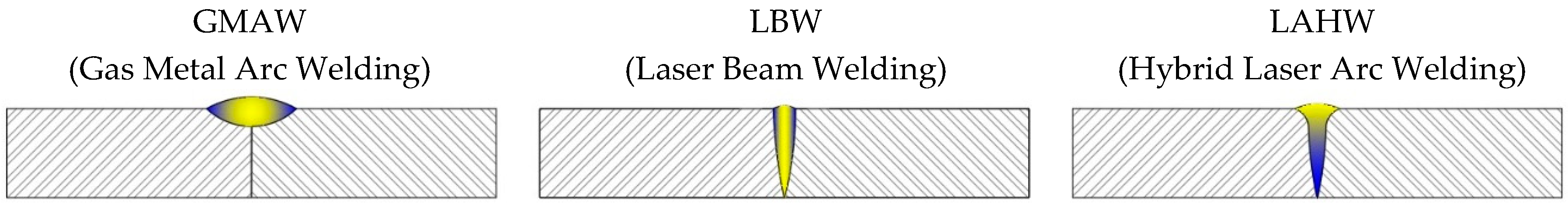
Figure 2.
Graphic diagram of the evolution of LAHW.

Figure 3.
Portal frame system for robot welding of ship structures (reproduced from [42] with company permission, Kranendonk Production Systems BV, Tiel, The Netherlands, 2018).
Figure 3.
Portal frame system for robot welding of ship structures (reproduced from [42] with company permission, Kranendonk Production Systems BV, Tiel, The Netherlands, 2018).

Figure 4.
Flow chart of main parameters in LAHW.

Figure 5.
Flow chart of process parameters in LAHW (Adapted from [67]).
Figure 5.
Flow chart of process parameters in LAHW (Adapted from [67]).
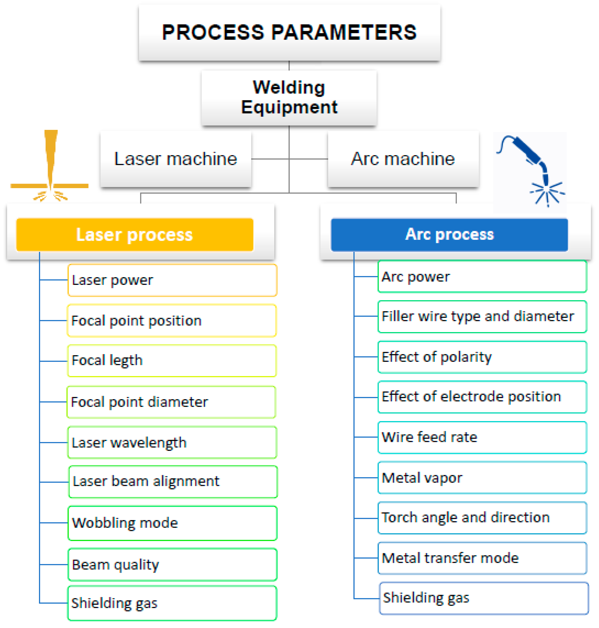
Figure 6.
Schemes of hybrid laser-arc welding process and parameters.

Figure 7.
Shape of MIG/MAG weld beads in butt joints: (a) convex and (b) concave welding.
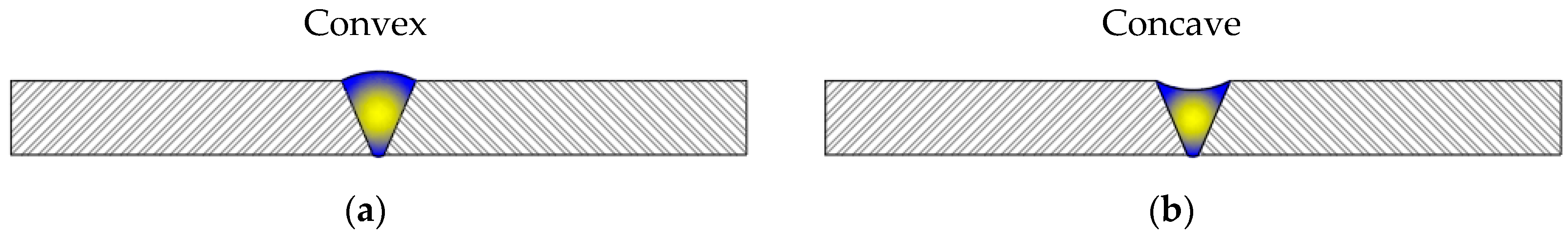
Figure 8.
Representative diagram of the hybrid welding process with cut-wire.

Figure 9.
Cross section of the three proposed designs of shielding gas nozzles for LAHW: (a) trapezoidal nozzle, (b) square nozzle with square section and (c) square nozzle with circular section. (Reproduced from [75] with permission, Springer London, 2017).
Figure 9.
Cross section of the three proposed designs of shielding gas nozzles for LAHW: (a) trapezoidal nozzle, (b) square nozzle with square section and (c) square nozzle with circular section. (Reproduced from [75] with permission, Springer London, 2017).

Figure 10.
Three-dimensional diagram of laser-MIG hybrid welding process, with an example of the arrangement of a trapezoidal nozzle for the shielding gas. (Adapted from [75] with permission, Springer London, 2017).
Figure 10.
Three-dimensional diagram of laser-MIG hybrid welding process, with an example of the arrangement of a trapezoidal nozzle for the shielding gas. (Adapted from [75] with permission, Springer London, 2017).

Figure 11.
Groove designs in hybrid welding process.

Figure 12.
Imperfections of hybrid laser welding: (a) pores (reproduced from [75] with permission, Springer London, 2017), and (b) crack (reproduced from [79] with permission, Elsevier, 2016).

Figure 13.
Microstructure of (a) the laser zone, (b) centre line after single pass and (c) centre line after second pass (reproduced from [80] with permission, Elsevier, 2017).
Figure 13.
Microstructure of (a) the laser zone, (b) centre line after single pass and (c) centre line after second pass (reproduced from [80] with permission, Elsevier, 2017).

Figure 14.
Microstructure evolution of the single pass hybrid followed by submerged arc: base material (a), partially recrystallized zone (b), fine grained zone (c), coarse grained zone (d), arc zone (e) and laser zone (f) (reproduced from [62] with permission, Elsevier, 2016).
Figure 14.
Microstructure evolution of the single pass hybrid followed by submerged arc: base material (a), partially recrystallized zone (b), fine grained zone (c), coarse grained zone (d), arc zone (e) and laser zone (f) (reproduced from [62] with permission, Elsevier, 2016).

Figure 15.
Macrograph of double-sided hybrid joint (a), microstructure of base material (b), laser zone (c) and arc zone (d), where F corresponds to polygonal ferrites, SGC to small granular carbides, CGB to columnar grain boundary and M to martensite (reproduced from [82] with permission, Elsevier, 2013).
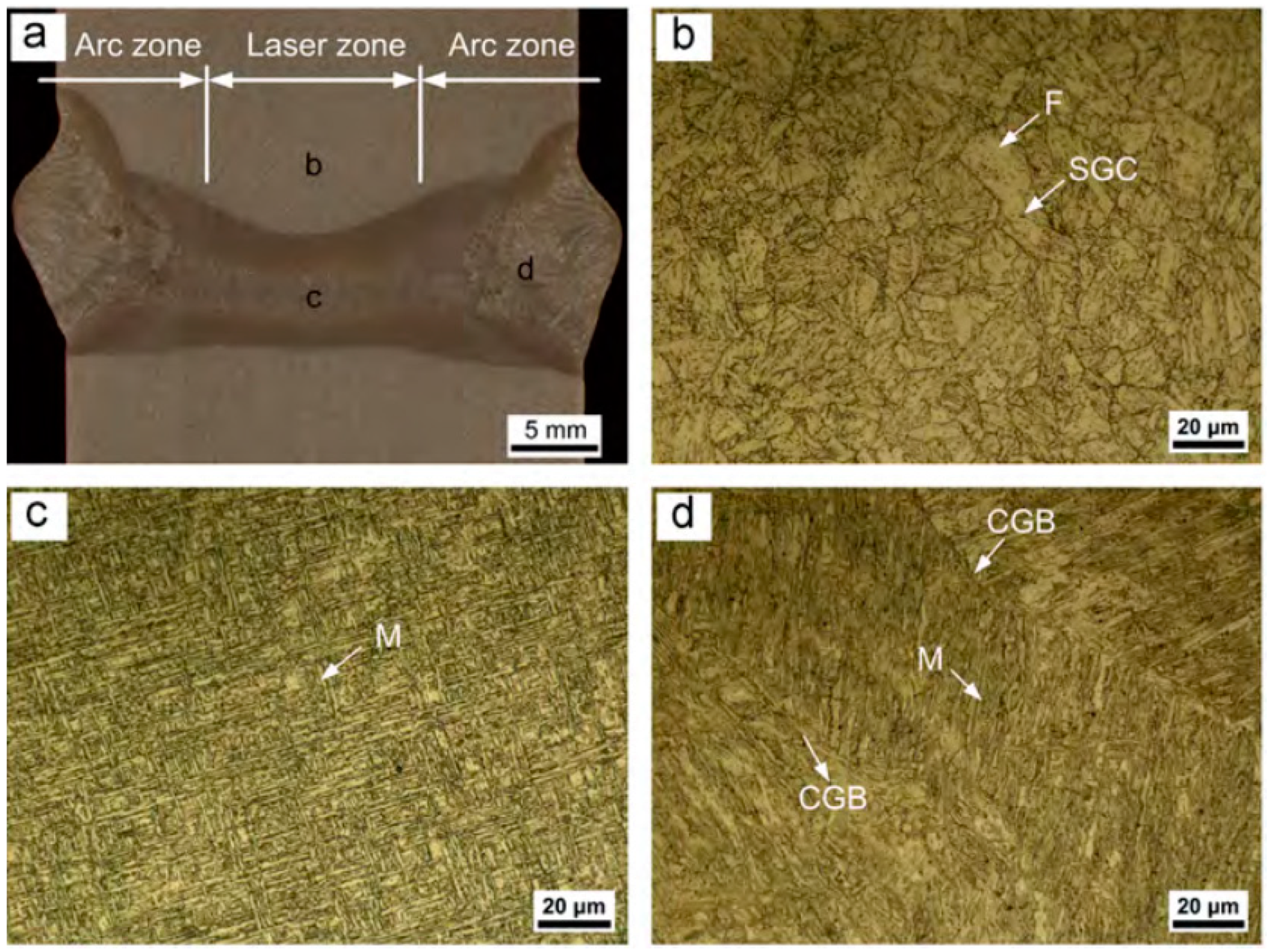
Figure 16.
EBSD mapping of base material (a) laser zone (b) and arc zone (c) (reproduced from [82] with permission, Elsevier, 2013).
Figure 16.
EBSD mapping of base material (a) laser zone (b) and arc zone (c) (reproduced from [82] with permission, Elsevier, 2013).

Figure 17.
Microstructures evolution in multi-passes LAHW: (a) laser zone and (b) its HAZ, (c) arc zone and (d) its HAZ (reproduced from [50] with permission, MDPI, 2017). Macrographic image of the whole weld is shown in Table 11R.

Figure 18.
Horizontal profiles of the 40 mm Q235 mild steel joint (reproduced from [50] with permission, MDPI, 2017).
Figure 18.
Horizontal profiles of the 40 mm Q235 mild steel joint (reproduced from [50] with permission, MDPI, 2017).


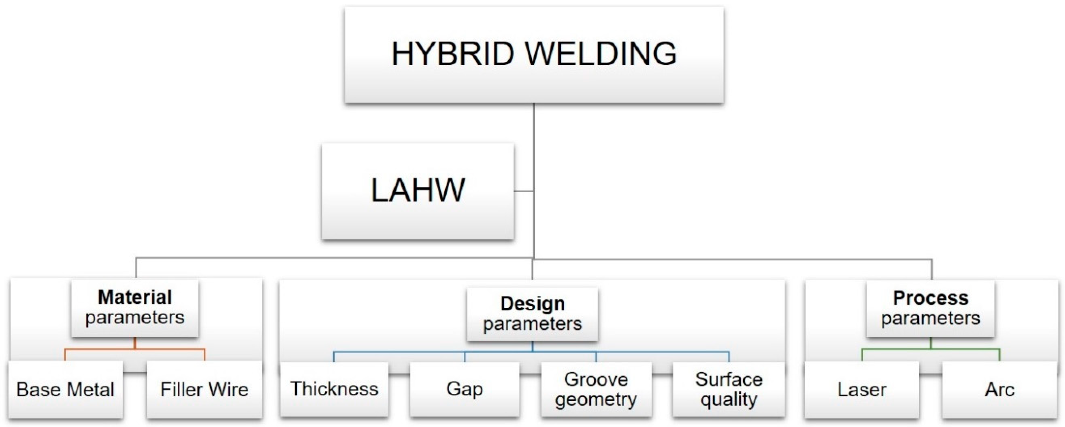
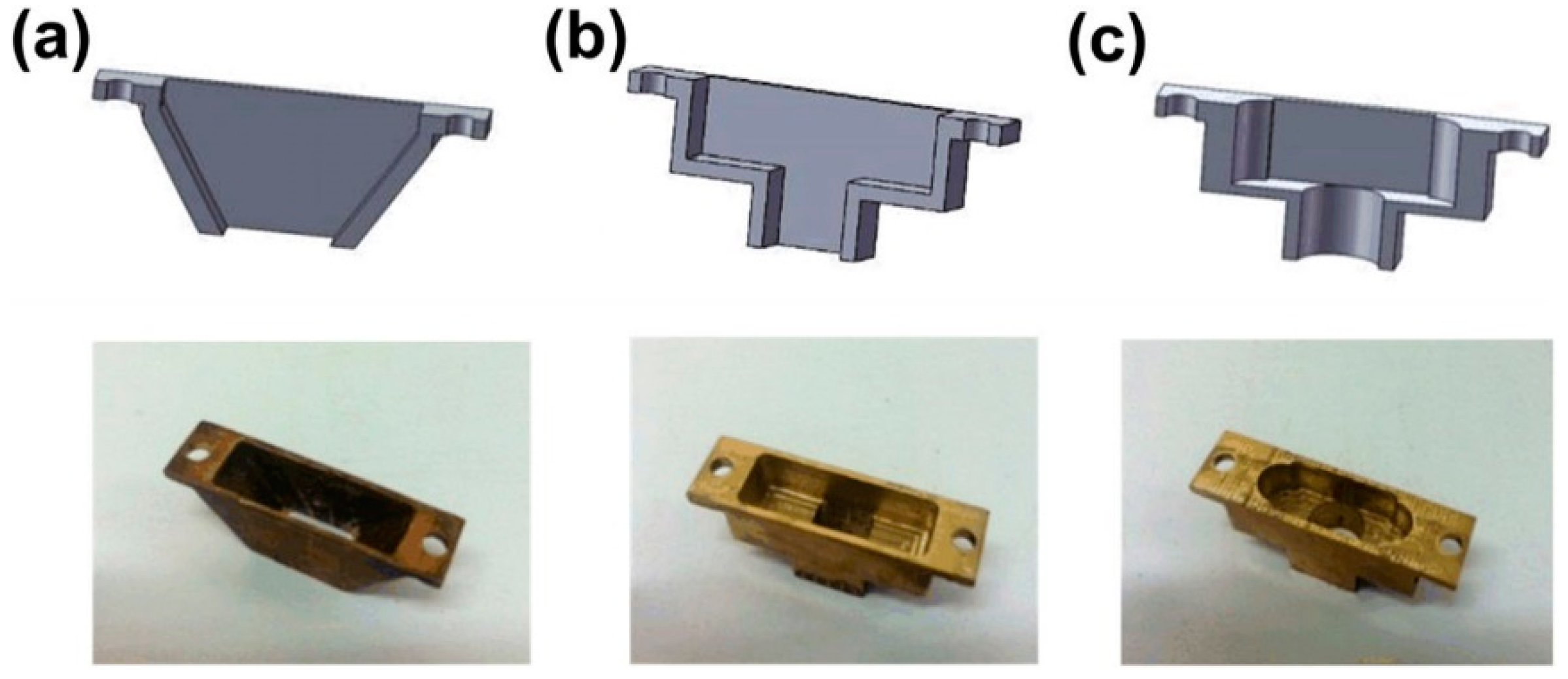
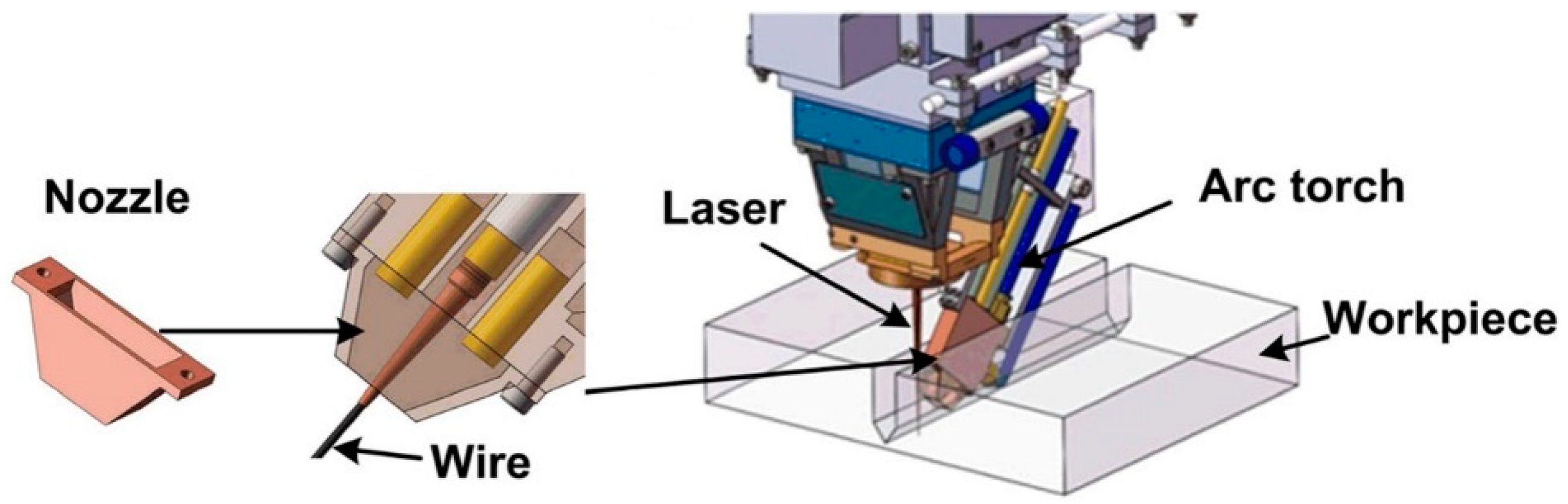
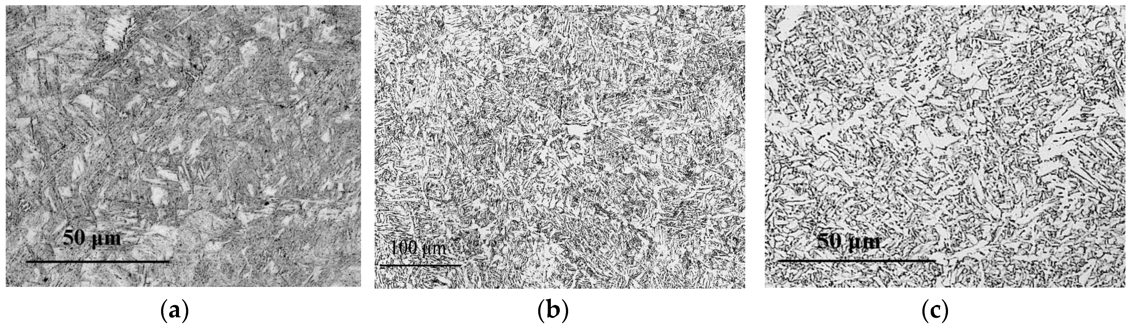
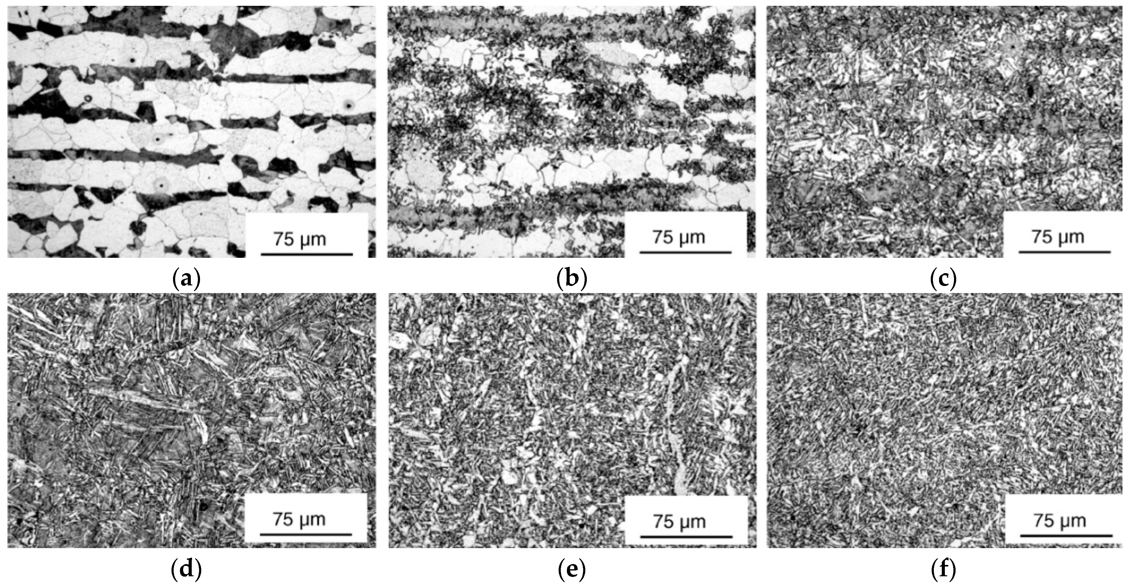
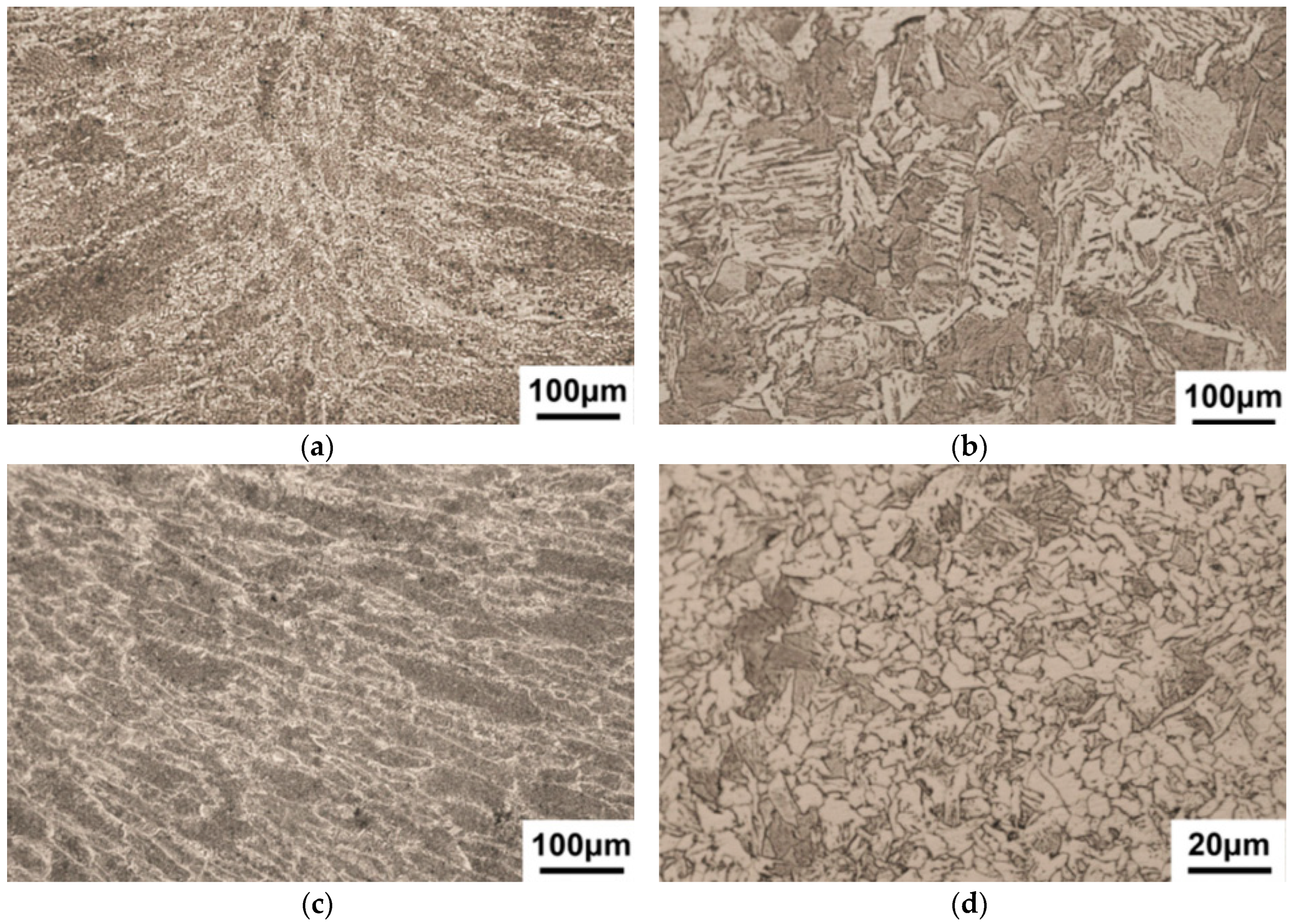
Table 1.
LAHW Welding standards.
| Identification | Description |
|---|---|
| ISO 12932:2013 | Welding. Laser-Arc Hybrid Welding of Steels, Nickel and Nickel Alloys. Quality Levels for Imperfections. |
| ISO 15614-14:2013 | Specification and Qualification of Welding Procedures for Metallic Materials. Welding Procedure Test. Part 14: Laser-Arc Hybrid Welding of Steels, Nickel and Nickel Alloys. |
| ISO 15609-6:2013 | Specification and Qualification of Welding Procedures for Metallic Materials. Welding Procedure Specification. Part 6: Laser-Arc Hybrid Welding. |
| ISO 15613:2004 | Specification and Qualification of Welding Procedures for Metallic Materials - Qualification Based on Pre-Production Welding Test. |
Table 2.
Nominal chemical composition of “Normal medium tensile ship” steel grades to Lloyd’s Rules: as-rolled, normalized, normalizing rolled or thermomechanically processed [32].
Table 2.
Nominal chemical composition of “Normal medium tensile ship” steel grades to Lloyd’s Rules: as-rolled, normalized, normalizing rolled or thermomechanically processed [32].
| Grade | Chemical Composition (wt.%) | ||||||||
|---|---|---|---|---|---|---|---|---|---|
| C | Mn | Si | P | S | Al | Nb | V | Ti | |
| max | min | max | max | max | min | max | |||
| A | 0.21 | 2.5 × C | 0.5 | 0.04 | 0.04 | - | - | - | - |
| AH32 | 0.18 | 0.9–1.6 | 0.5 | 0.035 | 0.03 | 0.015 | 0.02–0.05 | 0.03–0.10 | 0.02 |
| AH36 | |||||||||
| AH40 | |||||||||
| B | 0.21 | 0.80 | 0.35 | 0.04 | 0.04 | - | - | - | - |
| D | 0.21 | 0.60 | 0.1–0.35 | 0.04 | 0.04 | 0.015 | - | - | - |
| DH32 | 0.18 | 0.9–1.6 | 0.5 | 0.035 | 0.03 | 0.015 | 0.02–0.05 | 0.03–0.10 | 0.02 |
| DH36 | |||||||||
| DH40 | |||||||||
| E | 0.18 | 0.70 | 0.1–0.35 | 0.04 | 0.04 | 0.015 | - | - | - |
| EH32 | 0.18 | 0.9–1.6 | 0.5 | 0.035 | 0.03 | 0.015 | 0.02–0.05 | 0.03–0.10 | 0.02 |
| EH36 | |||||||||
| EH40 | |||||||||
| FH32 | 0.16 | 0.9–1.6 | 0.5 | 0.025 | 0.025 | 0.015 | 0.02–0.05 | 0.03–0.10 | 0.02 |
| FH36 | |||||||||
| FH40 | |||||||||
Table 3.
Mechanical properties of “Normal medium tensile ship” steel grades to Lloyd’s Rules: as-rolled, normalized, normalizing rolled or thermomechanically processed [32].
Table 3.
Mechanical properties of “Normal medium tensile ship” steel grades to Lloyd’s Rules: as-rolled, normalized, normalizing rolled or thermomechanically processed [32].
| Mechanical Properties | |||||
|---|---|---|---|---|---|
| Grade | Yield Strength, YS (min) | Ultimate Tensile Strength, UTS | Elongation, ΔL (min) | Charpy V (min) | |
| MPa | MPa | % | °C | J | |
| A | 235 | 400–490 | 22 | - | - |
| AH32 | 315 | 440–590 | 22 | 0 | 31 |
| AH36 | 355 | 490–620 | 21 | 0 | 34 |
| AH40 | 390 | 510–650 | 20 | 0 | 41 |
| B | 235 | 400–490 | 22 | - | 27 |
| D | 235 | 400–490 | 22 | −20 | 27 |
| DH32 | 315 | 440–590 | 22 | −20 | 31 |
| DH36 | 355 | 490–620 | 21 | −20 | 34 |
| DH40 | 390 | 510–650 | 20 | −20 | 41 |
| E | 235 | 400–490 | 22 | −40 | 27 |
| EH32 | 315 | 440–590 | 22 | −40 | 31 |
| EH36 | 355 | 490–620 | 21 | −40 | 34 |
| EH40 | 390 | 510–650 | 20 | −40 | 41 |
| FH32 | 315 | 440–590 | 22 | −60 | 31 |
| FH36 | 355 | 490–620 | 21 | −60 | 34 |
| FH40 | 390 | 510–650 | 20 | −60 | 41 |
Table 4.
Nominal chemical composition and Yield Strength of High tensile steels [55].
Table 4.
Nominal chemical composition and Yield Strength of High tensile steels [55].
| Grade | Nominal Chemical Composition (wt.%) | Yield Strength (min) | |||||||||
|---|---|---|---|---|---|---|---|---|---|---|---|
| C | Mn | Si | Cr | Mo | Ni | Nb | V | Cu | ksi | MPa | |
| HY80 | 0.15 | 0.25 | 0.25 | 1.4 | 0.4 | 2.7 | - | 0.01 | - | 80 | 550 |
| HSLA 80 | 0.04 | 0.55 | 0.30 | 0.7 | 0.2 | 0.9 | 0.04 | - | 1.2 | 80 | 550 |
| HY 100 | 0.15 | 0.25 | 0.25 | 1.4 | 0.4 | 2.9 | - | 0.01 | - | 100 | 690 |
| HSLA 100 | 0.04 | 0.90 | 0.25 | 0.6 | 0.6 | 3.5 | 0.03 | - | 1.6 | 100 | 690 |
Table 5.
Chemical composition of the pipe line steel API 5LX65 [56].
Table 5.
Chemical composition of the pipe line steel API 5LX65 [56].
| Chemical Composition (wt.%) | ||||||||||
|---|---|---|---|---|---|---|---|---|---|---|
| Steel | C | Si | Mn | P | S | Cr | Ni | Cu | Mo | Fe |
| API 5L X65 | 0.08 | 0.28 | 1.67 | 0.012 | 0.001 | 0.01 | 0.01 | 0.19 | 0.01 | Bal |
Table 6.
Chemical composition of the welding wires.
| Chemical Composition (wt% Maximum) | ||||||||||||||||
|---|---|---|---|---|---|---|---|---|---|---|---|---|---|---|---|---|
| Base Metal | Filler Wire | Ø (mm) | Ref. | C | Si | Mn | P | S | Cr | Ni | Cu | V | Nb | Mo | Ti+Zr | Fe |
| RS E36 | Pb 60M | 1.6 | [57] | 0.04 | 0.40 | 1.30 | - | - | - | 0.40 | - | - | - | - | - | Bal. |
| 0.08 | 0.80 | 1.60 | 0.015 | 0.015 | - | 0.60 | - | - | - | - | - | |||||
| S355J2 API 5L X65 | G3 Nil | 1.2 1.6 | [56] [57] [58] | 0.06 0.14 | 0.50 0.90 | 1.00 1.60 | 0.02 | 0.02 | 0.15 | 0.80 1.50 | 0.35 | 0.03 | - | 0.15 | 0.15 | Bal. |
| S235 S355 API 5L X65 | G3 Sil | 1.2 | [56] [49] [59] | 0.05 | 0.86 | 1.38 | 0.009 | 0.011 | 0.02 | 0.02 | 0.09 | 0.004 | <0.001 | <0.005 | - | Bal. |
| HSLA Steel plates | Trustarc MX-A55T | 1.2 | [60] [61] | 0.06 | 0.35 | 1.41 | 0.011 | 0.017 | - | 1.48 | - | - | - | - | - | Bal. |
| SM490A With cut-wire | MG-50 YM-26 ER70SG | 1.0 | [62] | 0.04 | 0.71 | 1.6 | 0.022 | 0.007 | - | - | 0.24 | - | - | - | 0.19 | Bal. |
| Q235 Mild steel | ER70S-6 | 1 | [50] | 0.08 | 0.92 | 1.52 | 0.020 | 0.015 | Others ≤ 0.5 | Bal. | ||||||
Table 7.
Mechanical properties of the welding wire.
| Filler Wire | Ultimate Tensile Strength, UTS | Yield Strength, YS | Elongation, ΔL | Impact Energy at −40 °C |
|---|---|---|---|---|
| MPa | MPa | % | J | |
| Pb 60M | 590–700 | >470 | ≥21 | ≥50 |
| ER70S-6 | ≥550 | ≥420 | ≥30 | ≥150 |
| G3 Ni1 | ≥570 | ≥450 | ≥26 | ≥45 |
Table 8.
Values range of parameters of LAHW.
| Laser Parameters | Common Parameters | |||||||||
|---|---|---|---|---|---|---|---|---|---|---|
| Ref. | Base Material | Thickness | Types | Power | λ * | BPP ** | Focal Length | Speed Welding | Distance Arc-Laser | Gap |
| (mm) | (kW) | (µm) | (mm*mrad) | (mm) | (m/min) | (mm) | (mm) | |||
| [47] | RS E36 | 20, 45 | Yb Fibre | 16 | 1070 | 8 | - | - | - | - |
| [56] | API 5L X65 | 20, 32 | Yb Fibre | 20 | 1070 | 11.2 | 350 | 2 | - | 0.5 |
| [57] | RS E36 | 7 | Fibre | 15 | 1070 | 6.7 | 400 | 4.3 | - | 0.3 |
| [49] | S235, S355, RQT701 | 30 | CO2 | 17 | - | - | 300 | 0.8 | 2 | 0.5 |
| [60] [61] [73] | HSLA | 45 (two-passes & cut-wire) | Yb Fibre | 15 | 1070 | 10.3 | 300 | 0.8–1.2 | 3.5–4.5 | 0.3–3.0 |
| [72] | AH36 | 20 | CO2 | 17 | - | - | 300 | 0.5 | 2 | 0.5 |
| [71] | Offshore steel YS > 420 MPa | 20 | Fibre | 15 | - | - | 300 | 8.3 | - | 0–1.35 |
* Wavelength, λ; ** Beam Parameter Product, BPP: quantifies the quality of a laser beam and how well it can be focused to a small spot. It is the product of a laser beam’s far-field divergence angle (half-angle) and the radius of the beam at its narrowest point (the beam waist).
Table 9.
Value range of parameters of arc welding process.
| GMAW Parameters | ||||||||||
|---|---|---|---|---|---|---|---|---|---|---|
| Ref. | Base Material | Thickness | Voltage | Intensity | Angle | Filler Wire | Wire Diameter | Feeding Rate | Gas Comp. | Flow Gas |
| (mm) | (V) | (A) | (degrees) | Comp. | (mm) | (m/min) | (%) | (l/min) | ||
| [47] | RS E36 | 20, 45 | 42 VAC 60 VDC | 420–550 | - | Pb 60 M | 1.2 | 10 | 80% Ar, 20% O2 | 25 |
| [56] | API 5L X65 | 20, 32 | 29.5–35.6 | 245–400 | 25 | G3Si1, G3Ni1 | 1.2 & 1.6 | - | - | - |
| [57] | RS E36 | 7 | 44 | 200–1500 | 30 | Pb 60M | 1.6 | 9.1 | 80% Ar, 20% O2 | 25 |
| [49] | S235, S355, RQT701 | 30 | 21–35.7 | - | - | G3Si1 | 1 | 6 | 10% Ar, 2% O2, He | 40 |
| [60] [61] [73] | HSLA | 45 (two-pass, cut-wire) | 20–36 | 250–440 | 20–30 | Trustarc MX-A55T | 1.2 | 8.3–12 | 82% Ar, 18% CO2 | 25 |
| [72] | AH36 | 20 | 27.1 | - | 20 | G3Si1 | 1 | 5 | 10% Ar, 2% O2, He | 40 |
| [71] | Offshore steel YS > 420 MPa | 20 (double-side) | 26 | 312 | 25 | 0.9% Ni, 0.09% C, 0.6% Si, 1.2% Mn | 1 | 3.3 | 92% Ar, 8% CO2 | 20 |
Table 10.
Joints configuration of hybrid welding process.
| Thickness (mm) | Steel | Hybrid Process | Process Configuration * | Groove Shape | Gap (mm) | Root Face Height (mm) | Angle | Ref. |
|---|---|---|---|---|---|---|---|---|
| 25 | AH36 | GMAW + CO2 | OS_MP | Y | 0.5 | 12 | 20° | [49,72] |
| S355J2 | GMAW + Disk | OS_MP | Y | 0 | 10 | 30° | [80] | |
| SM490A | GMAW + Fibre + cut wire | OS_MP | S | 2.5 | 0 | - | [62,81] | |
| S355J2 | GMAW + Disk | DS_SP OS_SP | S Y | 0 | - 6 to 8 | - | [79] [80] | |
| 28 | API 5L X65 | Fibre | OS_MP | Y | - | 16 | 45° | [56] |
| 30 | AH36 | GMAW + CO2 | OS_MP | Y | 0.5 | 12 | 20° | [49] |
| RQT701 | GMAW + CO2 | DS_SP | DY | 0.5 | 3 | 6°/10° | [49] | |
| High strength | GMAW + Fibre | DS_MP | K | 0.3–0.6 | 10 | 30° | [82] | |
| 32 | API 5L X65 | Fibre | OS_MP | U | 0 | 18 | 45° | [56] |
| 35 | API 5L X65 | SAW + Disk | DS_SP | DY | 0 | 25 | 70° | [83] |
| 60° | ||||||||
| 40 | Q235 | GMAW + Fibre | OS_MP | U | 6 | - | [50] | |
| P265GH | SAW + Disk | DS_SP | DY | 0 | 30 | 60° | [83] | |
| HSLA | GMAW + Fibre | DS_SP | DY | 0.6 | 5 | 4° | [73] | |
| S355 J2+N | GMAW | DS_MP | I | 0.5 | 5 20 | 14° 22° | [76] | |
| GMAW + SAW | DY | 0 | 20 | 45° | [59] | |||
| 50 | SM490A | GMAW + Fibre + cut wire | DS_SP | S | 2.5 | 0 | - | [62,81] |
* OS_SP—One Sided Single Pass welding; OS_MP—One sided multi passes technique; DS_SP—Double sided single pass; DS_MP—Double sided multi passes.
Table 11.
Cross sections of the thick steel hybrid laser joints.
| A | B | C | D | E | |
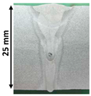 |  |  |  | 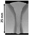 | |
| AH36 H1, T3 [49,72] | S355J2 H3, T3 [79] | S355J2 H3, T1 [80] | S355J2 H3, T2 [80] | SM490A H2+CW, T2 [62] | |
| F | G | H | I | J | |
 |  |  | 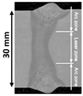 |  | |
| API 5L X65 H2, T2 [56] | RQT701 H1, T3 [49] | AH36 H1, T2 [49] | High-strength H2, T4 [82] | API 5L X65 H2, T2 [56] | |
| K | L | M | N | O | |
 | 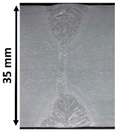 |  |  | 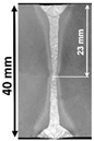 | |
| API X65 H5, T3 [83] | API X65 H4, T3 [83] | API X65 H4, T3 [83] | S355 J2+N H0, T3 [76] | HSLA H2+CW, T3 [60] | |
| P | Q | R | S | T | |
 | 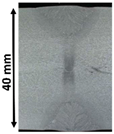 | 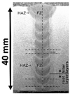 |  | 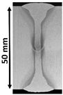 | |
| S355J2+N H6, T4 [59] | P265GH H4, T3 [83] | Q235 H2, T2 [50] | S355 J2+N H0, T4 [76] | SM490A H2+CW, T3 [62] | |
| U | |||||
 | All macros were adapted. H0—GMAW arc + laser H1—GMAW arc + CO2 laser H2—GMAW arc + Fibre laser H3—GMAW arc + Disk laser | H4—SAW arc + Disk laser H5—SAW arc + CO2 laser H6—GMAW + SAW CW—Cut Wire Technique | T1—OS_SP T2—OS_MP T3—DS_SP T4 - DS_MP | ||
| S460 H5, T3 [83] | |||||
© 2019 by the authors. Licensee MDPI, Basel, Switzerland. This article is an open access article distributed under the terms and conditions of the Creative Commons Attribution (CC BY) license (http://creativecommons.org/licenses/by/4.0/).
Share and Cite
MDPI and ACS Style
Churiaque, C.; Chludzinski, M.; Porrua-Lara, M.; Dominguez-Abecia, A.; Abad-Fraga, F.; Sánchez-Amaya, J.M. Laser Hybrid Butt Welding of Large Thickness Naval Steel. Metals 2019, 9, 100. https://doi.org/10.3390/met9010100
AMA Style
Churiaque C, Chludzinski M, Porrua-Lara M, Dominguez-Abecia A, Abad-Fraga F, Sánchez-Amaya JM. Laser Hybrid Butt Welding of Large Thickness Naval Steel. Metals. 2019; 9(1):100. https://doi.org/10.3390/met9010100
Chicago/Turabian StyleChuriaque, Cristina, Mariane Chludzinski, Manuel Porrua-Lara, Antonio Dominguez-Abecia, Francisco Abad-Fraga, and Jose Maria Sánchez-Amaya. 2019. "Laser Hybrid Butt Welding of Large Thickness Naval Steel" Metals 9, no. 1: 100. https://doi.org/10.3390/met9010100
Note that from the first issue of 2016, this journal uses article numbers instead of page numbers. See further details here.