Article

Numerical and Experimental Investigations of Solidification Parameters and Mechanical Property during Laser Dissimilar Welding

1
Key Laboratory of Mechanics in Advanced Manufacturing, Institute of Mechanics, Chinese Academy of Sciences, Beijing 100190, China
2
School of Engineering Science, University of Chinese Academy of Science, Beijing 100049, China
*
Authors to whom correspondence should be addressed.
Metals 2018, 8(10), 799; https://doi.org/10.3390/met8100799
Submission received: 31 August 2018 / Revised: 28 September 2018 / Accepted: 30 September 2018 / Published: 5 October 2018
(This article belongs to the Special Issue Laser Welding of Industrial Metal Alloys)

Abstract

:
Laser beam welding (LBW) has been considered an effective fusion welding method for the dissimilar welding of 304 stainless steel and Ni. However, the principles governing the correlations between the heat input, weld dimension, solidified microstructure and mechanical properties have not been fully studied before. Therefore, LBW experiments with variable heat input were carried out. A transient, three-dimensional model considering liquid metal convection was developed, and solidification parameters such as temperature gradient (G), growth rate (R), and cooling rate (GR) were calculated through thermal analysis to validate the experimental results. Then, microhardness tests were carried out to verify the predications made by the simulation. Energy dispersive spectroscopy (EDS) measurements were performed to study the mass transfer. The results indicate that the joints produced by LBW were nearly defect-free. The heat input per unit length is more effective at characterizing the influence of heat input on weld dimensions. The heat input has a greater influence on the cooling rate (GR) than the morphology parameter (G/R). The results demonstrate that both the solidification characteristics and mechanical property are greatly affected by the thermal behavior in the molten pool.

1. Introduction

Nickel and nickel-based alloys have excellent corrosion resistance [1], and 304 stainless steel is a Cr-Ni stainless steel with excellent heat resistance and machinability [2]. Joints of Ni and 304ss are widely used in the fields of petrochemical, steel metallurgy, and aerospace. Laser beam welding (LBW) has attracted increasing attention for the advantages of the high precision, lower heat input, and flexible transmission [3,4]. Both the Ni and 304ss show good welding adaptability to LBW [5]. However, due to differences in thermal and mechanical properties such as thermal conductivity, heat capacity, and viscosity, etc., brittle intermetallic compounds are prone to occur, and elements at the grain boundaries are easily enriched in dissimilar welding [6]. Therefore, the joint is susceptible to cracks and failures. Simulations on thermal behavior and solidification parameters in the molten pool could be used to qualitatively predict the solidification microstructure and mechanical properties [7]. The simulations and experimental studies reported in this paper intend to optimize the process parameters, and hence, improve the joint quality.
Thermal behavior and solidification characteristics during welding process have received increasing research interest over the past decades, albeit largely limited to studies on the joints of similar metals. The liquid metal convection and solidification parameters (i.e., temperature gradient G, growth rate R, G/R and GR) during LBW of 304ss were studied by He et al. [8]. The fluid flow and the effect of various solidification parameters during gas tungsten arc welding (GTA) of pure aluminum were investigated by Farzadi et al. [9]. The correlations between the electrode positive ratio, cooling rate, and microstructure of variable polarity gas tungsten arc welding (VP-GTAW) were numerically and experimentally studied by Wang et al. [10]. Study interest of the solidification mechanism and its effect on mechanical properties considering the liquid metal convection of the molten pool continues to grow. However, when it comes to the welding of dissimilar metals, most studies are restricted to the heat conduction models, and the significant effect of solidification parameters on the microstructure and mechanical properties has not been fully invesitgated. The temperature field calculated by heat conduction equation and microstructure evolution during friction stir welding (FSW) of Al-Mg were investigated by Skeikh Ahmad et al. [11]. The correlations of thermal characteristics and microhardness during LBW of AA 6165 and AA 6056 aluminum alloys were studied by Yang et al. [12] using a three dimensional fluid flow model, but the effect of the solidification parameters on the microstructure was not considered. Therefore, it is urgent to study the influence of the solidification parameters on the final microstructure and the mechanical characteristics during dissimilar joints.
In this study, experiments of laser dissimilar welding of 304ss and Ni with different heat input, but the same laser power, were first conducted. Then, a transient, three-dimensional model considering the heat transfer and fluid flow was developed to study transient thermal behavior; this was then validated against the experimental results. The solidification parameters were calculated to predict the morphology and the scale of the solidified microstructure. Microhardness tests were carried out to verify the qualitative prediction of the mechanical property. Chemical profile across the joints under different heat input was obtained by EDS experiments. The principles governing the correlations between the heat input, weld geometry, solidified microstructure, and microhardness were clearly elaborated.

2. Experimental Procedure
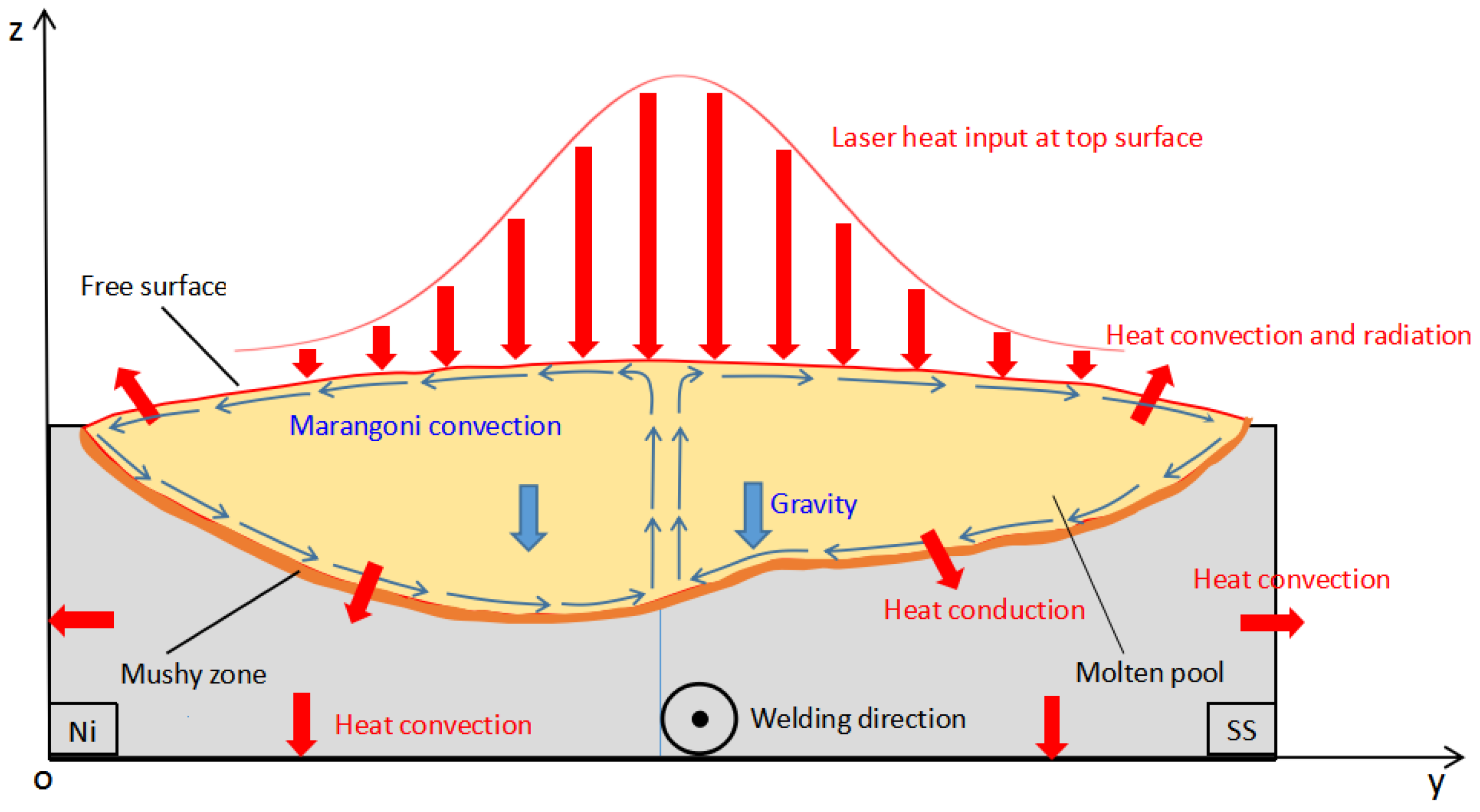
Ni and 304ss alloy sheets were used in the laser conduction welding experiments; the size was 40 mm × 40 mm × 2 mm. The shape and size of the specimens used in the experiments are also shown in Figure 1. The chemical composition of these specimens is shown in Table 1. The laser welding system (Institute of Mechanics, Chinese Academy of Sciences, Beijing, China) for the experiments consists of Nd: YAG continuous fibre laser, five-axis computerized numerical control (CNC) working system and clamping platform. Before welding, oil and other impurities were removed using acetone. The laser welding parameters applied in the experiments are presented in Table 2.
After the experiments, metallographic samples were prepared by sectioning the welded joints along the vertical direction using an electrical discharge wire cutting machine (HZHF, Shenzhen, China). Then, the samples were etched in a HCL:HNO3 solution with a volume ratio of 3:1 after the processes of rough grinding, fine grinding, and polishing. The microstructure of the treated specimen was observed by TR-MC light microscope (OM) (Shanghai CSOIF Co., Ltd., Shanghai, China) and ZEISS EV18 scanning electron microscopy (SEM) (ZEISS, Heidenheim, Germany) equipped with Oxford INCA energy dispersive spectrometer (EDS) (Oxford Instruments, Oxford, UK). Microhardness tests were carried out with the MVK-H300 Vickers microhardness tester (Akashi, Akashi, Japan) under the load of 50 g and a dwell time of 15 s. The test points were selected at intervals of 100 µm.

3. Numerical Model

In this study, a transient, three-dimensional numerical model considering the heat transfer, fluid flow, and the free surface deformation was developed to investigate the dissimilar joint of 304ss and Ni. The schematic diagram of the dissimilar welding is presented in Figure 2.
To simplify the mathematical calculation, the numerical model was calculated under some major assumptions: the flow of the liquid metal was Newtonian, laminar, and incompressible; the laser heat input at the top surface was Gaussian distribution; the mushy zone was a porous medium; relevant thermal and physical properties, such as thermal conductively, specific heat, are assumed to vary linearly with temperature.
The conservation equations of mass, momentum, and energy calculated for the molten pool are formulated as Equations (1)–(3).
Conservation of mass,
ρ t + ( ρ u ) = 0
Conservation of momentum,
ρ u t + ρ ( u ) u = [ p l + μ ( u + ( u ) T ) 2 3 u ( u ) l ] + F
Conservation of energy,
ρ C p T t + ρ C p u T = ( K T ) ρ ( Δ H ) t ρ u ( Δ H )
where ρ and u represent the density and the velocity vector, respectively. The μ and p are the viscosity of the fluid and the pressure, respectively. Cp is the specific heat, T is the temperature and K is the thermal conductivity. F represents the frictional dissipation of momentum in the mushy zone according to the Carman-Kozeny equation for flow through porous media [13,14], which is expressed as:
F = ( 1 f l ) 2 f l 3 + B A u
In this study, fl is the liquid fraction, A is a numerically large number, and B is a small number to avoid the division of fl by zero. The liquid fraction is given as:
f l = { 0 , 0 < T < T s T T s T l T s , T s < T < T l 1 , T > T l
where Tl and Ts represent the liquidus and solidus temperatures, respectively.
H is the latent enthalpy content, which is given as:
Δ H = L f l
where L denotes the latent heat of fusion.
The heat flux at liquid/gas interface is described as:
q ener = 2 η Q π r b 2 exp ( 2 r 2 r b 2 ) h c ( T T 0 ) σ b ε ( T 4 T 0 4 )
where η is the absorption efficiency of the material, and Q is the nominal laser power. r and rb are the distance from the grid node to the center of the laser beam and the effective radius of the laser beam, respectively. hc is the convection heat transfer coefficient, σb is the Stefan-Boltzmann constant, ε is the emissivity, and T0 is the ambient temperature.
In this study, the absorption coefficient was assumed to be related to the wavelength and the substrate resistivity [15], and could be expressed as:
η ( T ) = 0.365 ( α λ ) 1 / 2 0.0667 ( α λ ) + 0.06 ( α λ ) 3 / 2
where λ represents the wavelength, and α is the electrical resistivity of the 304ss and Ni. For 304ss, the average electrical resistivity is 80 µΩ·cm [16], and for nickel, it is 69 µΩ·cm [17]. The wavelength of the Nd: YAG laser is 1.064 µm. Based on the properties mentioned above, the calculated absorption coefficients are 0.27 for 304ss and 0.25 for nickel, respectively. Thus, the absorption coefficient is assumed to be 0.26 for both the 304ss and nickel, in order to simplify the numerical model.
The laser energy is irradiated onto the base metals in the form of thermal flux, as shown in Figure 3. The unit of the power density is W/m2. Convection and radiation are applied to the bottom and lateral boundaries of both the solid and fluid domain, viz:
q loss = h c ( T T 0 ) + σ b ε ( T 4 T 0 4 )
The boundary condition at the liquid/gas interface considering the free surface deformation is described as:
F L / G = σ n κ s T d σ d t
The two terms at the right hand of the Equation (10) represent the capillary force and thermocapillary force, respectively. σ represents the surface tension, n* represents the normal of the free surface, and κ is the curvature of the free surface. Thermal boundaries are illustrated in Figure 2, and momentum boundaries may be found in a previous study [18].
The parameters used for simulation and material properties are presented in Table 3 and Table 4, respectively. In the calculation, the effect of temperature on thermal and physical properties were also considered. The thermal and physical properties used in the simulation were taken to be different for the solid and liquid phases, and varied linearly with temperature. The free surface was captured by the moving mesh method based on the Arbitrary Lagrangian Eulerian [19] in this work. The boundary of the moving mesh could be expressed as:
V L / G = u L / G n
where uL/G is the velocity at the liquid/gas interface.
The model geometry and mesh grids for numerical simulation is shown in Figure 4. Quadratic polynomials were used for the discretization for the whole domain, and all the equations were solved by using SIMPLE solver. A fine unstructured tetrahedral mesh with maximum element size of 120 µm was applied in the fluid domain, while a tetrahedral mesh with a maximum element size of 400 µm was specified in the solid domain where only the heat conduction equation was solved. The mesh grids consist of 13,884 nodes and 79,191 domain units, with a maximum time step of 0.1 ms.
The heat input per unit length during the dissimilar welding, E, is defined as E = Q/V [7], where Q is the laser power and V is the welding speed. As shown in Table 5, the effect of heat input was investigated by varying the welding speed in this study.
During welding process, solidified structure and mechanical properties are significantly affected by the thermal behavior in the molten pool, which could be characterized by the solidification parameters. The temperature gradient G, which is normal to the solidification front, can be calculated by [23]:
G = T
The solidification growth rate R, can be expressed as:
R = u T / x G
where u is the welding speed. The parameters of temperature gradient G and growth rate R are directly calculated from the transient thermal analysis of the numerical model. Then, the morphology parameter G/R and cooling rate GR could be obtained to study the solidification mechanism of the grain morphology and dimensions.

4. Results and Discussion

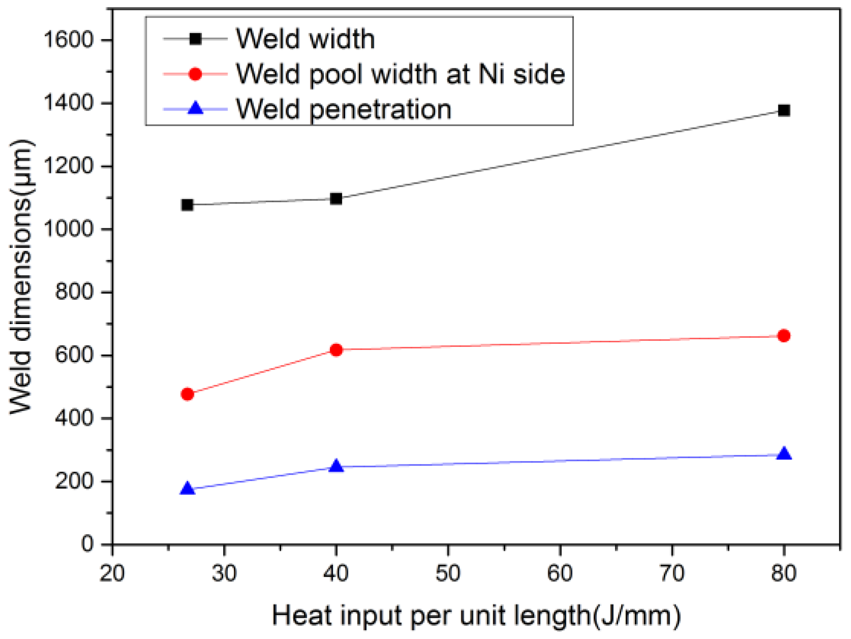
4.1. Influence of Heat Input on the Weld Formation

Both arc and laser beam welding (LBW) could be used for the joint of 304 stainless steel due to their good welding adaptability. However, for nickel and nickel-based alloys, because of poor plasticity and permeability, the joint of nickel is prone to defects such as pores and cracks when arc welding is adopted [17], but shows good adaptability to LBW [24]. Figure 5 shows the weld beads for laser dissimilar welding under different heat input; the joints of 304ss and Ni by LBW are nearly defect-free. It is demonstrated that LBW is an effective fusion welding method for dissimilar welding of 304ss and nickel. As the scanning speed increases from 10 mm/s to 20 mm/s to 30 mm/s, the heat input per unit length is reduced from 80 J/mm to 40 J/mm to 26.7 J/mm, respectively. As a result, the weld width decreases from 1.377 mm to 1.097 mm to 1.077 mm.

4.2. Influence of Heat Input on the Weld Pool Configuration

The temperature field and velocity distribution under different heat input are shown in Figure 6. Temperature field is indicated by the contour, while the velocity field is characterized by both the contour and arrows. Liquid metal is driven from the center of the molten pool towards the fusion boundary due to the negative coefficient of surface tension. The weld pool configurations on both sides are obviously different for the great difference of thermal and physical properties between 304ss and Ni. As can be seen from Figure 6a–c, the area of the top surface of the molten pool decreases with the heat input. In this study, the maximum velocity in the weld pool varies from 0.56 mm/s to 0.63 mm/s, while the maximum temperature is close to 3000 K under different settings. It can be concluded that the heat input has a relatively greater effect on the velocity than the temperature distribution in the molten pool during the welding process.
The numerical model is validated by comparing the calculated and experimentally-observed weld pool configuration under a heat input of 26.7 J/mm, as illustrated in Figure 7. The computed weld pool dimensions are reasonably consistent with the experimental results, which indicates the efficiency of the model. As can be seen from Figure 7, the weld pool depths on both sides are different. The weld pool penetration of the 304ss side is smaller. Because the convection in the 304ss side is more pronounced [5] and the surface tension temperature coefficient is negative, the intense outward flow is induced by the surface tension (Figure 6), and the molten pool on the 304ss side is shallower compared with that at the Ni side. In this study, the free surface deformation at the gas-liquid interface is captured by the moving mesh method based on the Arbitrary Lagrange Eulerian [19], as shown in Figure 7a. It is also illustrated in Figure 7a that the velocity at the top area of the melt pool is faster in the joint of 304ss and Ni, since the fluid flow is mainly driven by the surface tension acting on the free surface.
The weld dimensions under different heat input are shown in Figure 8. Both the weld depth and the weld width increase with the heat input. When the welding speed changes from 10 mm/s to 20 mm/s, the change of the weld width is much larger than that from 20 mm/s to 30 mm/s, because the change of heat input per unit length from 10 mm/s to 20 mm/s is obviously larger. It is also demonstrated that the heat input per unit length is more effective to characterize the effect of heat input on the weld dimensions compared with welding speed. The weld pool on both sides shows great differences during the dissimilar welding of 304ss and Ni. In the previous discussion, the difference in the weld pool penetration has been studied. As shown in Figure 8, the weld width changes with the heat input, but the weld pool width at Ni side is generally half of the whole weld width at different heat input. This is because the difference between the melting point of 304ss and Ni is small, i.e., 1727 K and 1735 K, respectively. Under the action of symmetrical Gaussian laser beam, the weld width on both sides tends to be equal.

4.3. Influence of Heat Input on the Microstructure

The effect of solidification parameters G/R and cooling rate GR on the solidified microstructure is shown in Figure 9. Parameter G/R affects the morphology of the structure and smaller G/R tends to produce equiaxed grains. The cooling rate GR affects the scale of the solidified structure; a larger GR has a higher tendency to produce finer solidified structure in the fusion zone. Figure 10 shows the spatial distribution of the parameter G/R at different heat input, and all the values are calculated along a horizontal line 0.1 mm below the weld surface, as shown in Figure 7b. The G/R gradually increases from the center to the edge on both sides, and the G/R at Ni side is larger than that at 304ss side, which indicates that equaixed grains are more likely to be produced near the weld center. The G/R for case 3 is the largest, followed by case 2 and case 1, but the difference of G/R between two different heat input is relatively small. The spatial distribution of the cooling rate GR at different heat input is shown in Figure 11, and the effect of heat input on GR is obviously observed. With a decrease of heat input from 80 J/mm to 40 J/mm to 26.7 J/mm, the cooling rate at the weld center changes from 2280 K/s to 12,976 K/s and 13,231 K/s, respectively. It can also be seen from Figure 11 that the GR decreases gradually from the center to the edge of the melt pool. The GR increases with the welding speed, but the change of GR from case 1 to case 2 is greater because the change of heat input per unit length in this situation is larger, as previously discussed. Therefore, it can be predicted that the solidification structure for case 3 is the finest, and the morphology of the solidified structure at different heat input in this study tends to be consistent, which will be verified by the experimental results in the next discussion.
Figure 12 shows the solidified structure at different heat input, which is observed in the area around the representative points illustrated in Figure 7b. As mentioned above, the value of the parameter G/R under different heat input is close, while the cooling rate (GR) shows great difference, and the value for case 3 is the largest, followed by case 2 and case 1. As shown in Figure 12, the change of heat input in this study has no effect on the morphology of the solidified structure, and the morphology of the solidified structure under different cases is similar. However, the heat input has a great influence on the scale of the solidification structure, as illustrated in Figure 12. It can be seen that a solidified structure for case 3 is the finest, and finer for case 2 than for case 1. The lower the heat input, the larger the cooling rate, and the finer the solidification structure. The experimental observations are consistent with the predictions form the solidification parameters shown in Figure 10 and Figure 11. Therefore, it can be concluded that the heat input has a greater influence on the scale of the solidification structure than the morphology of the microstructure. Finer solidification structure could be obtained by decreasing the heat input during the dissimilar laser welding of 304ss and nickel. The microstructure dimensions are important for the control of the welding quality, and finer grains usually result in better mechanical properties [26]. For example, the microhardness of the finer solidification structure is higher than that of the coarse structure, and higher microhardness shows good wear performance. Therefore, the mechanisms of the correlations between heat input, solidification parameters, solidified structure, and mechanical properties are studied to obtain finer structures and better mechanical performance.

4.4. Influence of Heat Input on the Elements Distribution

Element distribution across the laser welding joint of stainless steel and nickel is shown in Figure 13, and the energy dispersive spectroscopy (EDS) measurements were performed along the horizontal line 0.1 mm below the free surface of the weld pool, as shown in Figure 7b. Major elements, such as Fe, Cr, and Ni, were experimentally measured under different heat input to study the effect of the heat input on the element distribution in the molten pool. During the evolution of the weld pool, elements in the 304ss, such as Fe and Cr, are transported from 304ss side to nickel side due to the Marangoni convention and diffusion. Similarly, the element of Ni is also transported from Ni side to 304ss side for the same mechanisms. The experimental results presented in Figure 13 also show the mass transfer mechanisms. For example, the mass faction of Ni is higher near the nickel side and lower near the 304ss side. As shown in Figure 13, the element distribution is greatly influenced by the heat input. With an increase of the heat input, the elements are more uniformly distributed. As discussed in the part 4.2 in this paper, higher heat input results in larger weld pool dimensions and longer solidification time; thus, the convection could be fully developed, and the elements are distributed more uniformly.

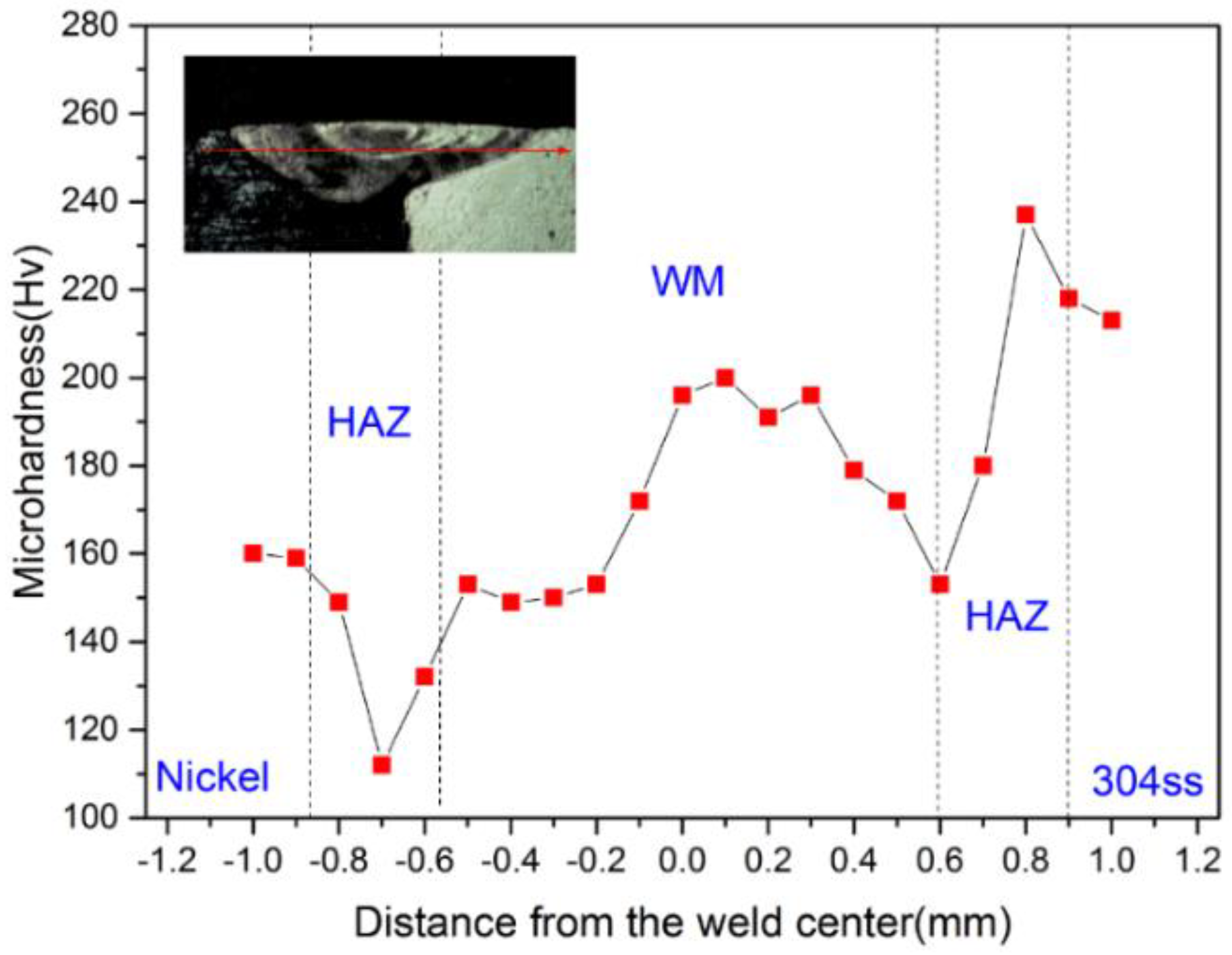
4.5. Influence of Heat Input on the Microhardness

Microhardness was measured along a horizontal line below the weld surface (the red line in Figure 7b). The Vickers hardness of the solidified structure at different heat input is obtained, as shown in Figure 14. The microhardness of 304ss and Ni base metal is 210 Hv and 160 Hv, respectively. It can be seen that the hardness at the heat input of 26.7 J/mm is the largest, followed by the hardness at the heat input of 40 J/mm and 80 J/mm. For the case of 26.7 J/mm, the cooling rate is the largest, as shown in Figure 11, and the corresponding structure is the finest, as illustrated in Figure 12; therefore, the hardness is the highest. The cooling rate at the heat input of 40 J/mm is larger and the grain dimension is finer compared with that at the heat input of 80 J/mm; thus, the microhardness is bigger. The variation of Vickers hardness is consistent with the variation of the cooling rate and the grain dimension in the fusion zone. The hardness increases gradually from nickel side to 304ss side because the hardness of 304ss base metal is higher than that of nickel. The formation of brittle of intermetallic compounds (IMCs) at the weld seam may also affect the microhardness, which would be considered in future study.
The microhardness of the joint of 304ss and Ni at the heat input of 40 J/mm is shown in Figure 15. The hardness of the fusion zone is higher than Ni but lower than 304ss base metal. The hardness of the heat-affected zone (HAZ) at Ni side is lower than that of the base metal, which is attributed to the coarse grains introduced by the solid phase transformation [27]. In the HAZ of the 304ss side, hardening occurs due to the self-quenching effect, and the hardness is higher than that of the base metal.
Figure 16a shows the microstructure and the calculated solidification parameters of the representative points of A, B, and C on the 304ss side, while Figure 16b shows that of the representative points of a, b, and c on the Ni side. As the location changes from A to B to C, the cooling rate decreases gradually and the microstructure becomes coarser; thus, the microhardness decreases. The effect of G/R on the morphology of the solidified structure is also illustrated here. With an increase of the parameter G/R, the equiaxed dendrites, the cellular dendrites and the planar are observed in the area around the representative points of A, B, and C, respectively. The similar effects of the G/R and GR are also found on the Ni side, as shown in Figure 16b. It can also be seen from Figure 16 that the relative difference of microhardness between the two points at the same depth in the weld pool is small, which indicates that the alloying elements are uniformly mixed throughout the weld zone.

5. Conclusions

A transient three-dimensional heat transfer and fluid model was developed for laser linear welding under different heat input. The weld pool configuration, solidification parameters, solidified microstructure, elements distribution, and microhardness were investigated numerically and experimentally. The primary results could be concluded as follows.
  • The joints produced by LBW are nearly defect-free, which proves that LBW is an effective fusion welding method for dissimilar welding of 304ss and nickel.
  • With an increase of welding speed, both the weld width and weld penetration decrease. The change of the weld dimension from case 1 to case 2 is much larger than that from case 2 to case 3. It is demonstrated that the heat input per unit length is more efficient to characterize the effect of heat input compared with welding speed.
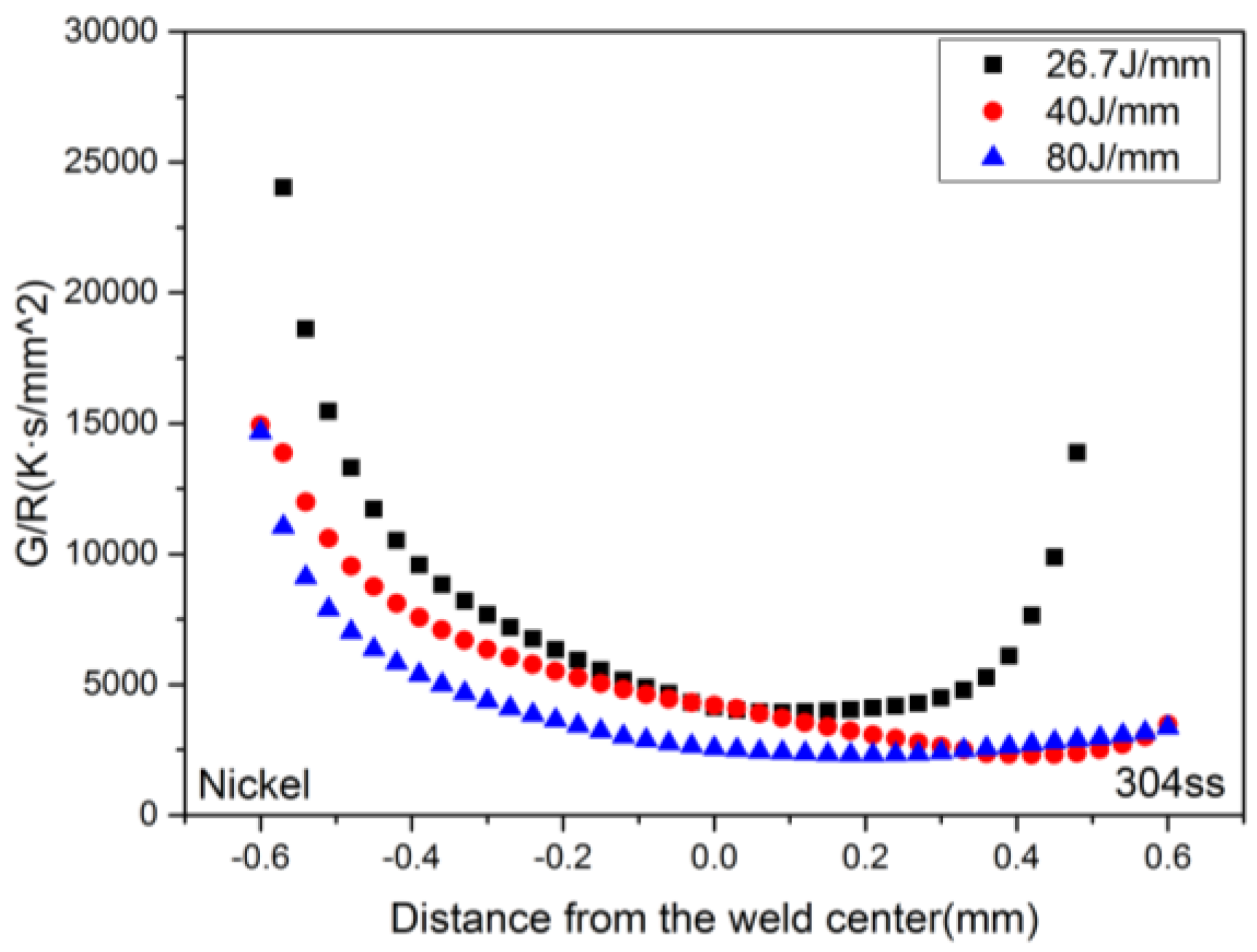
  • The heat input has more influence on the cooling rate (GR) than the morphology parameter (G/R). As a result, the morphology of the solidified microstructure at different heat input in this study is similar, but the scale is quite different and the solidified structure for case 3 is the finest.
  • The microhardness of the solidification structure is greatly affected by the grain dimension. In this investigation, the Vickers hardness of case 3 is the largest, followed by case 2 and case 1. It was found that the lower the heat input, the higher the hardness in the fusion zone.

Author Contributions

Y.Z. and S.L. arranged the welding experiments. X.H. and Z.L. contributed to the metallographic preparation and the investigations of microstructure and microhardness. Z.L. performed the simulation and wrote this paper. G.Y. and X.H. checked and modified this paper.

Acknowledgments

This study was funded by the National Natural Science Foundation of China under grant numbers 11272316, 11272317, 11672304, and 11502269. In addition, the authors are grateful for the instrument developing project of the Chinese Academy of Sciences (No. yz201636) and the Pilot Project B of the Chinese Academy of Sciences (xdb).

Conflicts of Interest

All of the authors declare that there is no conflict of interest.

References

  1. Bahrami, A.; Valentine, D.T.; Helenbrook, B.T.; Aidun, D.K. Study of mass transport in autogenous GTA welding of dissimilar metals. Int. J. Heat Mass Transf. 2015, 85, 41–53. [Google Scholar] [CrossRef]
  2. Mishin, O.V.; Gertsman, V.Y.; Alexandrov, I.V.; Valiev, R.Z. Grain boundary character distributions and mechanical properties of 304 stainless steel. Mater. Sci. Eng. A 1996, 212, 281–283. [Google Scholar] [CrossRef]
  3. Yu, G.; He, X.L.; Li, S.X. Laser Manufacturing and Its Application; National Defense Industry Press: Beijing, China, 2017; pp. 93–97. ISBN 978-7-118-10984-9. [Google Scholar]
  4. Boccarusso, L.; Arleo, G.; Astarita, A.; Bernardo, F.; De Fazio, P.; Durante, M.; Memola Capece Minutolo, F.; Sepe, R.; Squillace, A. A new approach to study the influence of the weld bead morphology on the fatigue behaviour of Ti–6Al–4V laser beam welded butt joints. Int. J. Adv. Manuf. Technol. 2017, 88, 75–88. [Google Scholar] [CrossRef]
  5. Hu, Y.; He, X.; Yu, G.; Zhao, S. Capillary convection in pulsed butt welding of miscible dissimilar couple. Mech. Sci. Technol. 2016, 231, 2429–2440. [Google Scholar] [CrossRef]
  6. Wu, J.; Zhang, H.; Feng, Y.; Luo, B. 3D Multiphysical Modelling of Fluid Dynamics and Mass Transfer in Laser Welding of Dissimilar Materials. Metals-Basel 2018, 8, 443. [Google Scholar] [CrossRef]
  7. Kou, S. Welding Metallurgy; John Wiley & Sons: New York, NY, USA, 2003; pp. 170–195. ISBN 0-471-43491-4. [Google Scholar]
  8. He, X.L.; Fuerschbach, P.W.; DebRoy, T. Heat transfer and fluid flow during laser spot welding of 304 stainless steel. J. Phys. D Appl. Phys. 2003, 36, 1388–1398. [Google Scholar] [CrossRef] [Green Version]
  9. Farzadi, A.; Serajzadeh, S.; Kokabi, A.H. Modeling of heat transfer and fluid flow during gas tungsten arc welding of commercial pure aluminum. Int. J. Adv. Manuf. Technol. 2008, 38, 258–267. [Google Scholar] [CrossRef]
  10. Wang, L.L.; Wei, J.H.; Wang, Z.M. Numerical and experimental investigations of variable polarity gas tungsten arc welding. Int. J. Adv. Manuf. Technol. 2018, 95, 2421–2428. [Google Scholar] [CrossRef]
  11. Ahmad, J.Y.S.; Ozturk, F.; Jarrar, F.; Evis, Z. Thermal history and microstructure during friction stir welding of Al-Mg ally. Int. J. Adv. Manuf. Technol. 2016, 86, 1071–1081. [Google Scholar] [CrossRef]
  12. Yang, Z.; Tao, W.; Zhao, X.; Chen, Y.; Shi, C. Numerical modelling and experimental verification of thermal characteristics and their correlations with mechanical properties of double-sided laser welded T-joint. Int. J. Adv. Manuf. Technol. 2017, 92, 1609–1618. [Google Scholar] [CrossRef]
  13. Voller, V.; Prakash, C. A fixed grid numerical modelling methodology for convection–diffusion mushy region phase-change problems. Int. J. Heat Mass Transf. 1987, 30, 1709–1719. [Google Scholar] [CrossRef]
  14. Brent, A.D.; Voller, V.R.; Reid, K.J. Eethalphy-Porosity technology for modeling convection-diffusion phase-change—Application to the melting of a pure metal. Numer. Heat Transf. 1988, 13, 297–318. [Google Scholar] [CrossRef]
  15. Mikaél’A, B. Infrared Radiation: A Handbook for Applications; Plenum: New York, NY, USA, 1968. [Google Scholar]
  16. Peckner, D.; Bernstein, I.M. Handbook of Stainless Steels; McGraw-Hill: New York, NY, USA, 1977. [Google Scholar]
  17. Zhang, Y.; Zhang, C.L.; Liu, Y.M.; Zhang, J.L.; Chen, H. Welding Technology of Dissimilar Metals; China Machine Press: Beijing, China, 2016; pp. 254–255. ISBN 978-7-111-53889-9. [Google Scholar]
  18. Bahrami, A.; Helenbrook, B.T.; Valentine, D.T.; Aidun, D.K. Fluid flow and mixing in linear GTA welding of dissimilar ferrous alloy. Int. J. Heat Mass Transf. 2016, 93, 729–741. [Google Scholar] [CrossRef]
  19. Souli, M.; Benson, D.J. Abitrary Lagrangian Eulerian and Fluid-Structure Interaction; Wiley: New York, NY, USA, 2010; pp. 3–45. ISBN 978-1-84821-131-5. [Google Scholar]
  20. Fuerschbach, P.W.; Eisler, G.R. Effect of laser spot weld energy and duration on melting and absorption. Sci. Technol. Weld. Join. 2002, 7, 241–246. [Google Scholar] [CrossRef]
  21. Chakraborty, N. The effects of turbulence on molten pool transport during melting and solidification processes in continuous conduction mode laser welding of copper nickel dissimilar couple. Appl. Therm. Eng. 2009, 9, 3618–3631. [Google Scholar] [CrossRef]
  22. Hu, Y.; He, X.; Yu, G.; Ge, Z.; Zheng, C.; Ning, W. Heat and mass transfer in laser dissimilar welding of stainless steel and nickel. Appl. Surf. Sci. 2012, 258, 5914–5922. [Google Scholar] [CrossRef] [Green Version]
  23. Wei, H.L.; Elmer, J.W.; DebRoy, T. Origin of grain orientation during solidification of an aluminum alloy. Acta Mater. 2016, 115, 123–131. [Google Scholar] [CrossRef] [Green Version]
  24. Sun, Z.; Ion, J.C. Laser welding of dissimilar metal combinations. J. Mater. Sci. 1995, 30, 4205–4214. [Google Scholar] [CrossRef]
  25. Lippold, J.C. Welding Metallurgy and Weldability; John Wiley & Sons: New York, NY, USA, 2014; p. 21. ISBN 978-1-118-23070-1. [Google Scholar]
  26. Zhang, Z.; Wu, Q.; Grujicic, M.; Wan, Z.Y. Monte Carlo simulation of grain growth and welding zones in friction stir welding of AA6082-T6. J. Mater. Sci. 2016, 51, 1882–1895. [Google Scholar] [CrossRef]
  27. Lehto, P.; Remes, H.; Saukkonen, T. Influence of grain size distribution on the Hall-Petch relationship of welded structural steel. Mater. Sci. Eng. A 2014, 592, 28–39. [Google Scholar] [CrossRef]
Figure 1. The shape and size of the specimen used in the experiments.
Metals 08 00799 g001
Figure 2. Schematic sketch of laser dissimilar welding.
Metals 08 00799 g002
Figure 3. The model of the Gauss heat source.
Metals 08 00799 g003
Figure 4. Model geometry and mesh grids for numerical simulation.
Metals 08 00799 g004
Figure 5. Weld beads by LBW at different heat input. (a) 80 J/mm. (b) 40 J/mm. (c) 26.7 J/mm.
Metals 08 00799 g005
Figure 6. Temperature field and velocity distribution under different heat input. (a) 80 J/mm. (b) 40 J/mm. (c) 26.7 J/mm.
Metals 08 00799 g006
Figure 7. Comparison of calculated and experimental weld pool configurations under a heat input of 26.7 J/mm. (a) Calculated weld pool configuration (b) Experimental weld configuration.
Metals 08 00799 g007
Figure 8. Weld dimensions under different heat input.
Metals 08 00799 g008
Figure 9. The effect of solidification parameters on the solidified microstructure, data from [25].
Metals 08 00799 g009
Figure 10. Spatial distribution of the G/R under different heat input.
Metals 08 00799 g010
Figure 11. Spatial distribution of the cooling rate (GR) under different heat input.
Metals 08 00799 g011
Figure 12. Solidified microstructure under different heat input. (a) Ni side. (b) 304ss side.
Metals 08 00799 g012
Figure 13. Element distribution under different heat input. (a) 80 J/mm, (b) 40 J/mm.
Metals 08 00799 g013
Figure 14. Spatial distribution of Vickers hardness along the transverse section of the fusion zone.
Metals 08 00799 g014
Figure 15. Spatial hardness distribution for laser welded joint of 304ss and Ni at the heat input of 40 J/mm.
Metals 08 00799 g015
Figure 16. Microhardness and microstructure of representative points at the heat input of 40 J/mm. (a) 304ss side. (b) Ni side.
Metals 08 00799 g016
Table 1. Chemical compositions of Ni and 304ss (automatic fraction (%)).
MaterialNiFeCrCPS
Ni99.70.062-0.08-0.015
304ss8.5Bal18~200.060.030.02
Table 2. Laser welding parameters.
Laser SpotShielding GasLaser PowerWelding Speed
0.57 mmPure argon (15 L/min)800 W10–30 mm/s
Table 3. Parameters used for calculation, data from [20].
ParameterValue
Ambient temperature300 K
Emissivity0.2
Stefan-Boltzmann constant5.67 × 10−8 (Wm-2·K-4)
Laser absorption coefficient0.26
Convection heat transfer coefficient100 (W/m2·K)
Table 4. Thermal physical properties used for the simulation, data from [21,22].
Property304ssNi
Liquidus temperature (K)17271735
Solidus temperature (K)16721730
Heat of fusion (kJ/kg)272290
Specific heat of solid (J/kg·K)711.28515
Specific heat of liquid (J/kg·K)836.8595
Thermal conductivity of solid(W/m·K)19.260.7
Effective thermal conductivity of liquid(W/m·K)50150
Solid density (kg/m3)74508900
Liquid density (kg/m3)69108880
Dynamic viscosity (kg/m·s)6.7 × 10−33.68 × 10−3
Surface tension (N/m)1.8721.778
Temperature coefficient of surface tension (N/m·K)−4.3 × 10−4−3.4 × 10⁻⁴
Table 5. Variation of heat input in this study.
Welding ParametersCase1Case 2Case 3
Welding speed (mm/s)102030
Heat input (J/mm)804026.7

