Effect of Negative Current on the Microstructure of Oxide Coatings Prepared by Hybrid Pulse Anodization

1
College of Materials Science and Engineering, Nanjing Tech University, Nanjing 211816, China
2
College of Materials Science and Engineering, Xi’an University of Technology, Xi’an 710048, China
*
Authors to whom correspondence should be addressed.
Metals 2019, 9(1), 22; https://doi.org/10.3390/met9010022
Submission received: 27 November 2018
/
Revised: 14 December 2018
/
Accepted: 22 December 2018
/
Published: 27 December 2018
Abstract
:The oxide coatings were prepared on 6061 Al alloy at different negative current densities in oxalic acid using the hybrid pulse anodization (HPA) method at room temperature. The variation curves of positive and negative voltages with anodization time were recorded. The nanopore diameters and distribution regularities in HPA coatings were analyzed with the Image-Pro Plus software based on field-emission scanning electron microscope (FE-SEM) images. The results showed that the negative current could reduce the growth rate of HPA coatings, and thus led to a small thickness of the coatings within the same anodization time. Besides, appropriate negative current densities resulted in the better distribution uniformity of nanopores, but the excessive negative current densities tended to cause inferior nanopore arrangement. These were attributed to the existence of the negative current, causing H+ and O2− to move in opposite directions, so that a large number of H+ concentrated on the surface of the HPA coatings, resulting in the accelerated dissolution of the coatings.
1. Introduction
In the past decades, porous anodic alumina (PAA) has attracted great attention as templates to produce different kinds of functional nanostructures such as nanowires and nanotubes [1]. It has been in widespread use in biological sensors [2], membrane reactors [3], energy storage devices [4], and super capacitors [5] for the regular and controllable nanopores. Most PAA coatings were fabricated using direct-current anodization (DCA) at potentiostatic mode in sulfuric acid (H2SO4) [6,7], oxalic acid (H2C2O4) [8,9,10], phosphoric acid (H3PO4) [11], chromic acid (H2CrO4) [12], and mixed acid electrolytes [13,14]. Much work have been done to explore the mechanism [15,16] of anodization. Besides, the influence of anodization parameters (such as potential [17,18], current density [19], electrolyte temperature, and anodization time [20]) on the microstructure and properties of PAA coatings has been also intensively studied. Studies found that during the anodization process, the growth and dissolution of aluminum oxide happened simultaneously and competed with each other. The Joule heat generated in anodization could accelerate the dissolution and destroy the uniformity of the PAA coatings [21]. Hence, DCA was generally carried out at low temperature (0–10 °C) to suppress the Joule heat. Cooling the electrolytes from room temperature was a time-consuming and cost-increasing process. Moreover, the low temperature was inclined to reduce the growth rate of PAA coatings, and in some cases, the processing time was even prolonged to dozens of hours [8].
In order to overcome these limitations in conventional DCA, pulse anodization (PA) was developed for the advantage of timely heat dissipation [21]. Many studies have investigated the effects of PA on the microstructure and properties of PAA coatings [22]. Bozza et al. [23] has reported that fewer defects were found at the oxide/metal interface proceeding with PA compared to DCA. Additionally, negative voltage was introduced into the PA process to improve the regularity of nanopores by suppressing the anodic current during the pulse-free time [24]. Chung et al. [25] has demonstrated that hybrid pulse anodization (HPA), which is pulse voltage including positive voltage together with low negative voltage (2V), could suppress the generation of Joule heat to reduce the dissolution rate of HPA coatings, and result in the better regularity of nanopores at room temperature [26]. In addition, Chung et al. [27] has demonstrated that a short pulse-off stage and low current density resulted in a better distribution and uniformity of nanopores in oxide coatings; on the country, the effective combination of a moderate duty cycle and high current density was able to accelerate the growth of HPA coatings. Although many works have proved that the HPA could enhance the distribution uniformity of the nanopores and improve the growth rate of oxide coatings, the role of negative current in HPA and the influence mechanisms of negative current are still not fully understood.
In this paper, the oxidation coatings were prepared at different negative currents using the HPA method. The effects of negative current on the microstructures and growth rates of oxidation coatings were analyzed, and the influence mechanisms were proposed.
2. Materials and Methods
2.1. HPA Process
First, 6061 alloy (0.8–1.2% Mg, 0.4–0.8% Si, 0.7% Fe, 0.15–0.4% Cu, 0.04–0.35% Cr, 0.25% Zn, 0.15% Mn, 0.15% Ti, and balance Al) plates with a thickness of 3 millimeter and diameter of 35 mm were employed as substrate materials, and the area of the aluminum sample for HPA was 20 cm2. Prior to the anodic oxidation process, specimens were firstly ground with SiC abrasive paper to 3000 mesh, and then immersed in 0.5 M of NaOH for 1 min at 50 °C to remove the natural oxide film. Subsequently, the specimens were rinsed with de-ionized water and dried in the air. The HPA process was carried out for 30 min in 0.3 M of oxalic acid electrolyte (C2H2O4·2H2O) with a volume of 4 liters in a rectangular plastic container using a bipolar pulse power supply. Figure 1 showed the schematic of the experimental set-up. Aluminum was set as the anode, and the stainless steel plate larger than the aluminum sample was set as the cathode. The distance between them was 5 centimeters. The temperature of the electrolyte was kept at 15 ± 3 °C by an air-blowing device to stir the electrolyte and an external circle cooling system simultaneously. The ton/toff, positive/negative pulse width ratio (t+/t−) and positive current density were set as 0.18, 1, and 5 A/dm2, respectively. The negative current densities varied from 0 to 3 A/dm2 with an increment of 0.5 A/dm2. After the HPA treatment, samples were ultrasonic cleaned in ethanol for 5 min and dried in the air.
2.2. Characterization
The thickness of the oxide coatings was measured with a handheld thickness gauge (FMP20, Helmut Fischer GMBH, Sindelfingen, Germany). The positive and negative voltages were recorded manually over the anodization time. The surface and cross-sectional morphologies of the anodized specimens were observed under a field-emission scanning electron microscope (FE-SEM, S-4800, Hitachi, Tokyo, Japan). The diameters and distribution of the nanopores in oxide coatings were analyzed with the software of Image-Pro Plus (Media Cybernetics, Rockville, MD, USA) based on FE-SEM images.
3. Results
3.1. Effect of Negative Current on Anodization Voltage
The variation curves of the positive and negative voltages with anodization time are presented in Figure 2. It can be seen that regardless of the negative current densities, the positive voltages exhibited similar variation trends. In the initial stage, the positive voltages rose rapidly to the peak, and then went down sharply. Subsequently, they kept increasing gradually until the end of HPA. Similar variation trends were observed for the negative voltages in Figure 2c. In addition, the peak values were obtained between 10 and 20 s (Figure 2b) due to the formation of a continuous and dense imperforate barrier layer, which had much higher resistance than the aluminum substrate [21,28]. The time that it took to reach the peak voltage was prolonged as the negative current density increased. Furthermore, the highest peak voltage of 140 V was found on the curve without the negative current, and the others declined as the negative current densities rose from 0 to 3 A/dm2. This was because the thickness of the barrier layer was reduced by the increased negative current density. After the voltages reached the peak, the nanopores started to appear due to the heterogeneous dissolution in the barrier layer [29]. At some points with small impurities and defects on the coating surface, the dissolution effect was enhanced to be stronger than the other areas of the surface. The current was concentrated in these places and the dissolution rate was accelerated; thus, the nanopores were formed [30]. As the coating thickness at the nanopores decreased, the resistance of the coatings began to reduce, and therefore, the voltage variation curves showed a downward tendency. As the HPA progressed, the nanopores continued to grow competitively until they achieved regular arrangement [15]. The voltages rose slowly along with the increase of the coating thickness until the end of anodization. Obviously, the final voltages were different (Figure 2a,c), which were closely related to the coating thickness.
3.2. Effect of Negative Current on Microstructures of HPA Coatings
Figure 3 displays the thickness of HPA coatings that were prepared at different negative current densities for 30 min. It could be found that the coating thickness decreased gradually with the increasing negative current densities. It was about 40 µm without negative current, while it reduced to 23 µm at the negative current density of 3.0 A/dm2. The variation trends of coating thickness were consistent with the values of the final voltages in Figure 2. Due to that, the coating growth rate was determined by an intense competition between the formation and dissolution of coatings, which proceeded simultaneously. The two inverse processes could be expressed in formulas (1) and (2), respectively [31]. The higher negative current density caused more H+ to move toward the coating/electrolyte interface under the action of an external electric field, thus accelerating the dissolution of the HPA coatings and ultimately leading to a decrease in the growth rate of the coatings.
2Al + 3[O] → Al2O3 + 1424 J/mol
Al2O3 + 6H+ → 2Al3+ + 3H2O
The surface SEM micrographs of anodization coatings prepared at different negative current densities for 30 min are presented in Figure 4. As can be seen, when there was no negative current during the HPA process, the surface of the anodization coating was smooth, and showed flowing morphology. In addition, the coating was compact with small-sized nanopores that were irregular in shape. When 1 A/dm2 of negative current density was applied, the nanopores got obviously much larger than those in Figure 4a,b. Continuously increasing the negative current density to 2 A/dm2, the nanopores turned a little bit larger. Besides, the surface of the coating became much flatter with less sediment, and the nanopores changed to have better distribution uniformity. It indicated that the application of negative current expanded the nanopores and obtained a well-ordered configuration. However, a large number of granular and interlacing stripe convexities appeared on the surface of anodization coatings when the negative current density reached 3 A/dm2. It caused the coating surface to be extremely uneven (Figure 4g,h). Beyond that, the nanopores arrangement turned disordered, and the nanopore diameter decreased markedly.
In order to further understand the nanopore diameters and their distribution, the FE-SEM images in Figure 4a,c,e,g were analyzed with the Image-Pro Plus software to identify their own characteristics. As shown in Figure 5, without negative current, the range of 20 ± 5 µm occupied the main distribution of all the nanopores. With the increase of negative current densities to 1 A/dm2 and 2 A/dm2, the diameters of nanopores were mainly distributed in 30 µm and 40 µm, respectively. It implied that the greater the negative current density, the larger the nanopore diameter. However, as the negative current density increased to 3A/dm2, the nanopore diameter became much smaller instead (Figure 5d).
4. Discussion
Figure 6 exhibits the schematic diagrams of two different current modes (PA and HPA). Compared with traditional DCA, the intermittent working principle was utilized in the PA process (Figure 6a). In a cycle, there was enough pulse-off time (toff) to dissipate the Joule heat generated (Formula (1)) in the anodization process (t+). Figure 6b shows the anodization current mode of HPA with a negative current. The negative current was applied to suppress the Joule heat generation by eliminating the anodic current during toff [30,31]. On the one hand, the dissolution reaction (Formula (2)) was weakened due to the timely dissipation of Joule heat; this was beneficial to decrease the dissolution rate of the coatings and lead to an increasing growth rate of anodizing coatings [22,24]. On the other hand, due to the conversion of positive and negative poles of power supply, O2− and H+ migrated to the cathode and anode, respectively. It resulted in the enhancement of the dissolution effect. There was a balance between the two sides to get a well-ordered nanopore configuration.
In a pulse period, H+ and O2− moved toward the cathode (steel plate) and the anode (Al substrate) separately when the positive current was applied at the beginning (Figure 7a). Ultimately, the O2− gathered around the anode (Figure 7c), and they were in direct contact with the Al substrate; then, Formula (1) occurred with Joule heat production. After that, the positive and negative poles of power supply switched, and H+ and O2− moved in opposite directions under the action of negative electric field (Figure 7b). The anodization process in Formula (1) stopped, and the Joule heat generated was taken away by water cooling during t− and toff. Large numbers of the H+ gathered on the surface of the coatings and in the nanopores (Figure 7d), accelerating the dissolution of the HPA coatings and playing the role of pore expansion and leveling the surface of coatings (Formula (2)) [28]. Besides, the greater the negative current was, the larger the driving force for H+. More H+ accumulated on the surface of the oxide coatings at the same time, making the dissolution rate of the coatings faster. On this occasion, the nanopore diameters became larger, and a better nanopore distribution uniformity was obtained. However, excessive H+ caused serious damage to the nanopore arrangement. Beyond that, the thickness obviously tended to get smaller because of the enhancement of the coating dissolution.
5. Conclusions
Anodization coatings have been successfully fabricated using the HPA method in oxalic acid. Results showed that the negative current could reduce the growth rate of anodization coatings, leading to the small thickness coatings within the same treating time. The coating thickness decreased from 40 to 23 µm as the negative current densities increased from 0 to 3 A/dm2. Besides, the nanopore diameters increased from 20 to 40 µm with the increase of negative current densities from 0 to 2 A/dm2. Appropriate negative current densities played the role of reaming pores and leveling surfaces to get better nanopore distribution uniformity. However, the surface flatness of the oxide coating was damaged seriously at excessive negative current densities, and inferior nanopore arrangement was obtained during the HPA process.
Author Contributions
The work was done in cooperation with the joint efforts of all the authors. B.J., H.L. and C.L. designed the experiments; S.H. and Q.S. performed the experiments; S.H., Q.S. and C.L. analyzed the experimental data; S.H. wrote the paper.
Funding
This research was funded by the National Natural Science Foundation of China (No. 51571114).
Acknowledgments
The authors gratefully acknowledge Dichun Chen for providing the FE-SEM.
Conflicts of Interest
The authors declare no conflict of interest.
References
- Kim, Y.; Lee, S.; Cho, H.; Park, B.; Kim, D.; Hwang, W. Robust superhydrophilic/hydrophobic surface based on self-aggregated Al2O3 nanowires by single-step anodization and self-assembly method. ACS Appl. Mater. Interfaces 2012, 4, 5074–5078. [Google Scholar] [CrossRef] [PubMed]
- Sriram, G.; Patil, P.; Bhat, M.P.; Hegde, R. Current trends in nanoporous anodized alumina platforms for biosensing applications. J. Nanomater. 2016, 2016, 1–24. [Google Scholar] [CrossRef]
- Yu, Y.; Wu, X.; Zhao, M.; Ma, Q.; Chen, J.; Chen, B.; Sindoro, M.; Yang, J.; Han, S.; Lu, Q.; et al. Anodized aluminum oxide templated synthesis of metal-organic frameworks used as membrane reactors. Angew. Chem. Int. Ed. 2017, 56, 578–581. [Google Scholar] [CrossRef]
- Liu, C.; Gillette, E.I.; Chen, X.; Pearse, A.J.; Kozen, A.C.; Schroeder, M.A.; Gregorczyk, K.E.; Lee, S.B.; Rubloff, G.W. An all-in-one nanopore battery array. Nat. Nanotechnol. 2014, 9, 1031–1039. [Google Scholar] [CrossRef] [PubMed]
- Liao, M.W.; Chung, C.K. Growth of porous anodized alumina on the sputtered aluminum films with 2D–3D morphology for high specific surface area. Appl. Surf. Sci. 2014, 309, 290–294. [Google Scholar] [CrossRef]
- Bensalah, W.; Feki, M.; Wery, M.; Ayedi, H.F. Thick and dense anodic oxide layers formed on aluminum in sulphuric acid bath. J. Mater. Sci. Technol. 2010, 26, 113–118. [Google Scholar] [CrossRef]
- Veys-Renaux, D.; Chahboun, N.; Rocca, E. Anodizing of multiphase aluminium alloys in sulfuric acid: In-situ electrochemical behaviour and oxide properties. Electrochim. Acta 2016, 211, 1056–1065. [Google Scholar] [CrossRef]
- Zhang, C.; Wang, K.G.; Gao, Z.Y.; Junjun, W.U.; Ren, J.Y. A kind of double-sided porous anodic alumina membrane fabricated with the three-step anodic oxidation method. Sci. China Technol. Sci. 2014, 57, 293–297. [Google Scholar] [CrossRef]
- Stępniowski, W.J.; Nowak-Stępniowska, A.; Bojar, Z. Quantitative arrangement analysis of anodic alumina formed by short anodizations in oxalic acid. Mater. Charact. 2013, 78, 79–86. [Google Scholar] [CrossRef]
- Zhang, R.; Jiang, K.; Zhu, Y.; Qi, H.; Ding, G. Ultrasound-assisted anodization of aluminum in oxalic acid. Appl. Surf. Sci. 2011, 258, 586–589. [Google Scholar] [CrossRef]
- Sanchez, A.G.; Schreiner, W.; Ballarre, J.; Cisilino, A.; Duffo, G.; Cere, S. Surface modification of titanium by anodic oxidation in phosphoric acid at low potentials. Part 2. In vitro and in vivo study. Surf. Interface Anal. 2013, 45, 1395–1401. [Google Scholar] [CrossRef]
- Elabar, D.; Hashimoto, T.; Qi, J.; Skeldon, P.; Thompson, G.E. Effect of low levels of sulphate on the current density and film morphology during anodizing of aluminium in chromic acid. Electrochim. Acta 2016, 196, 206–222. [Google Scholar] [CrossRef]
- Songjiang, M.; Peng, L.; Haihui, Z.; Chaopeng, F.; Yafei, K. Preparation of anodic films on 2024 aluminum alloy in boric acid-containing mixed electrolyte. Trans. Nonferr. Met. Soc. China 2008, 18, 825–830. [Google Scholar]
- Shih, H.; Tzou, S. Study of anodic oxidation of aluminum in mixed acid using a pulsed current. Surf. Coat. Technol. 2000, 124, 278–285. [Google Scholar] [CrossRef]
- Li, J.; Zhang, Z.; Li, Y.; Ma, Y.; Chen, L. Self-organization process of aluminum oxide during hard anodization. Electrochim. Acta 2016, 213, 14–20. [Google Scholar] [CrossRef]
- Pashchanka, M.; Schneider, J.J. Origin of self-organisation in porous anodic alumina films derived from analogy with Rayleigh–Bénard convection cells. J. Mater. Chem. 2011, 21, 18761–18767. [Google Scholar] [CrossRef]
- Bai, A.; Hu, C.; Yang, Y.; Lin, C. Pore diameter control of anodic aluminum oxide with ordered array of nanopores. Electrochim. Acta 2008, 53, 2258–2264. [Google Scholar] [CrossRef]
- Choudhary, R.K.; Mishra, P.; Kain, V.; Singh, K.; Kumar, S.; Chakravartty, J.K. Scratch behavior of aluminum anodized in oxalic acid: Effect of anodizing potential. Surf. Coat. Technol. 2015, 283, 135–147. [Google Scholar] [CrossRef]
- Christoulaki, A.; Dellis, S.; Spiliopoulos, N.; Anastassopoulos, D.L.; Vradis, A.A. Controlling the thickness of electrochemically produced porous alumina membranes: The role of the current density during the anodization. J. Appl. Electrochem. 2014, 44, 701–707. [Google Scholar] [CrossRef]
- Pniowski, W.J.S.; Pniowska, A.N.; Presz, A.; Czujko, T.; Varin, R.A. The effects of time and temperature on the arrangement of anodic aluminum oxide nanopores. Mater. Charact. 2014, 91, 1–9. [Google Scholar] [CrossRef]
- Chung, C.; Liu, T.Y.; Chang, W.T. Effect of oxalic acid concentration on the formation of anodic aluminum oxide using pulse anodization at room temperature. Microsyst. Technol. 2010, 16, 1451–1456. [Google Scholar] [CrossRef]
- Roshani, M.; Sabour Rouhaghdam, A.; Aliofkhazraei, M.; Heydari Astaraee, A. Optimization of mechanical properties for pulsed anodizing of aluminum. Surf. Coat. Technol. 2017, 310, 17–24. [Google Scholar] [CrossRef]
- Bozza, A.; Giovanardi, R.; Manfredini, T.; Mattioli, P. Pulsed current effect on hard anodizing process of 7075-T6 aluminium alloy. Surf. Coat. Technol. 2015, 270, 139–144. [Google Scholar] [CrossRef]
- Chung, C.K.; Chang, W.T.; Liao, M.W.; Chang, H.C.; Lee, C.T. Fabrication of enhanced anodic aluminum oxide performance at room temperatures using hybrid pulse anodization with effective cooling. Elecctrochim. Acta 2011, 56, 6489–6497. [Google Scholar] [CrossRef]
- Chung, C.K.; Chang, W.T.; Liao, M.W.; Chang, H.C. Effect of pulse voltage and aluminum purity on the characteristics of anodic aluminum oxide using hybrid pulse anodization at room temperature. Thin Solid Films 2011, 519, 4754–4758. [Google Scholar] [CrossRef]
- Keller, F.; Hunter, M.S.; Robinson, D.L. Structural features of oxide coatings on aluminum. J. Electrochem. Soc. 1953, 100, 411–419. [Google Scholar] [CrossRef]
- Chung, C.K.; Liao, M.W.; Chang, H.C.; Chang, W.T.; Liu, T.Y. On characteristics of pore size distribution in hybrid pulse anodized high-aspect-ratio aluminum oxide with Taguchi method. Microsyst. Technol. 2013, 19, 387–393. [Google Scholar] [CrossRef]
- Mohammadi, I.; Ahmadi, S.; Afshar, A. Effect of pulse current parameters on the mechanical and corrosion properties of anodized nanoporous aluminum coatings. Mater. Chem. Phys. 2016, 183, 490–498. [Google Scholar] [CrossRef]
- Wang, Y.; Santos, A.; Evdokiou, A.; Losic, D. Rational design of ultra-short anodic alumina nanotubes by short-time pulse anodization. Electrochim. Acta 2015, 154, 379–386. [Google Scholar] [CrossRef]
- Bononi, M.; Giovanardi, R.; Bozza, A. Pulsed current hard anodizing of heat treated aluminum alloys: Frequency and current amplitude influence. Surf. Coat. Technol. 2016, 307, 861–870. [Google Scholar] [CrossRef]
- Mohammadi, I.; Afshar, A. Modification of nanostructured anodized aluminum coatings by pulse current mode. Surf. Coat. Technol. 2015, 278, 48–55. [Google Scholar] [CrossRef]
Figure 1.
The schematic of the experimental set-up.

Figure 2.
Variation curves of positive (a,b) and negative (c,d) voltages with anodization time during hybrid pulse anodization (HPA) process for 30 min.
Figure 2.
Variation curves of positive (a,b) and negative (c,d) voltages with anodization time during hybrid pulse anodization (HPA) process for 30 min.
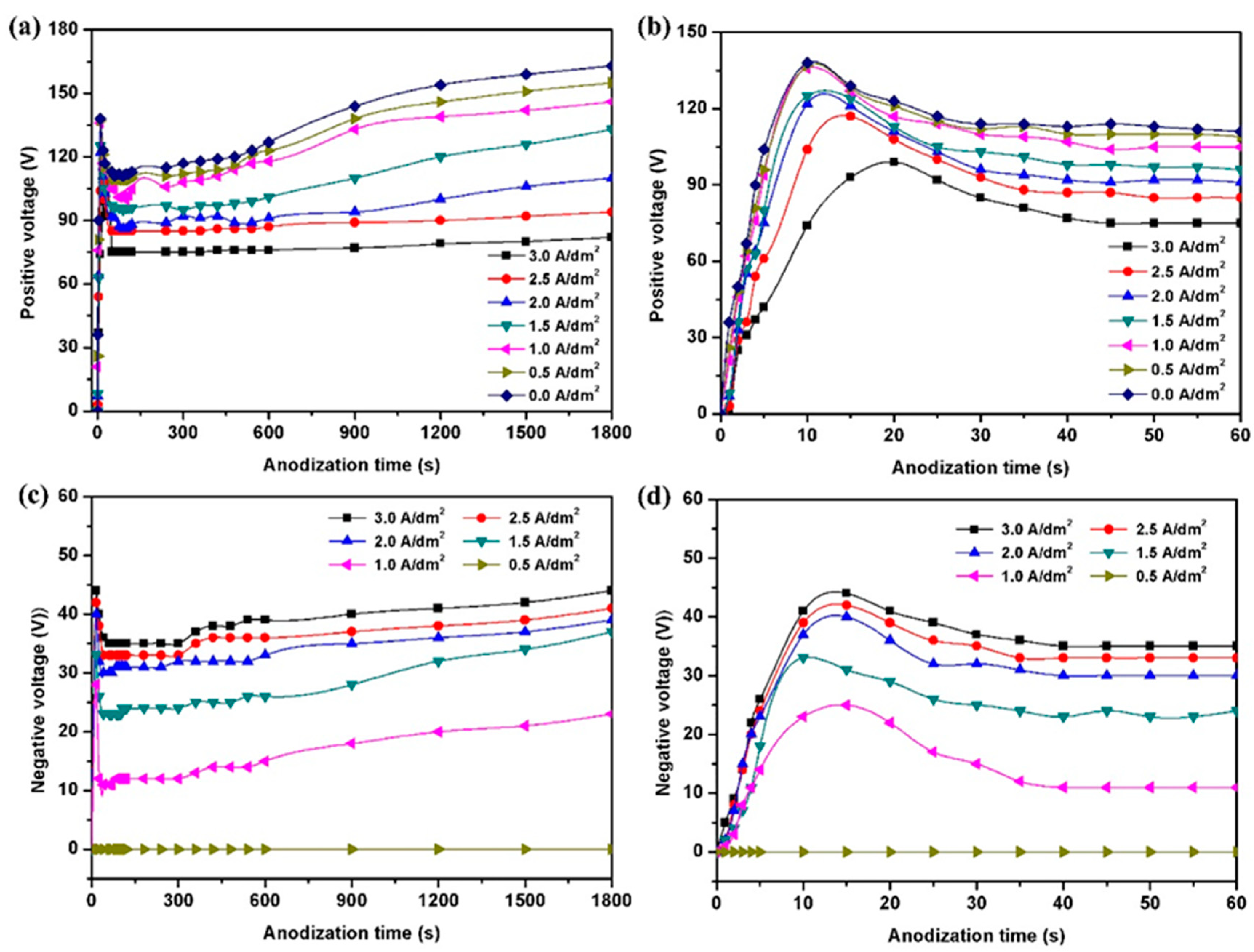
Figure 3.
The thickness of HPA coatings prepared at different negative current densities for 30 min.
Figure 3.
The thickness of HPA coatings prepared at different negative current densities for 30 min.
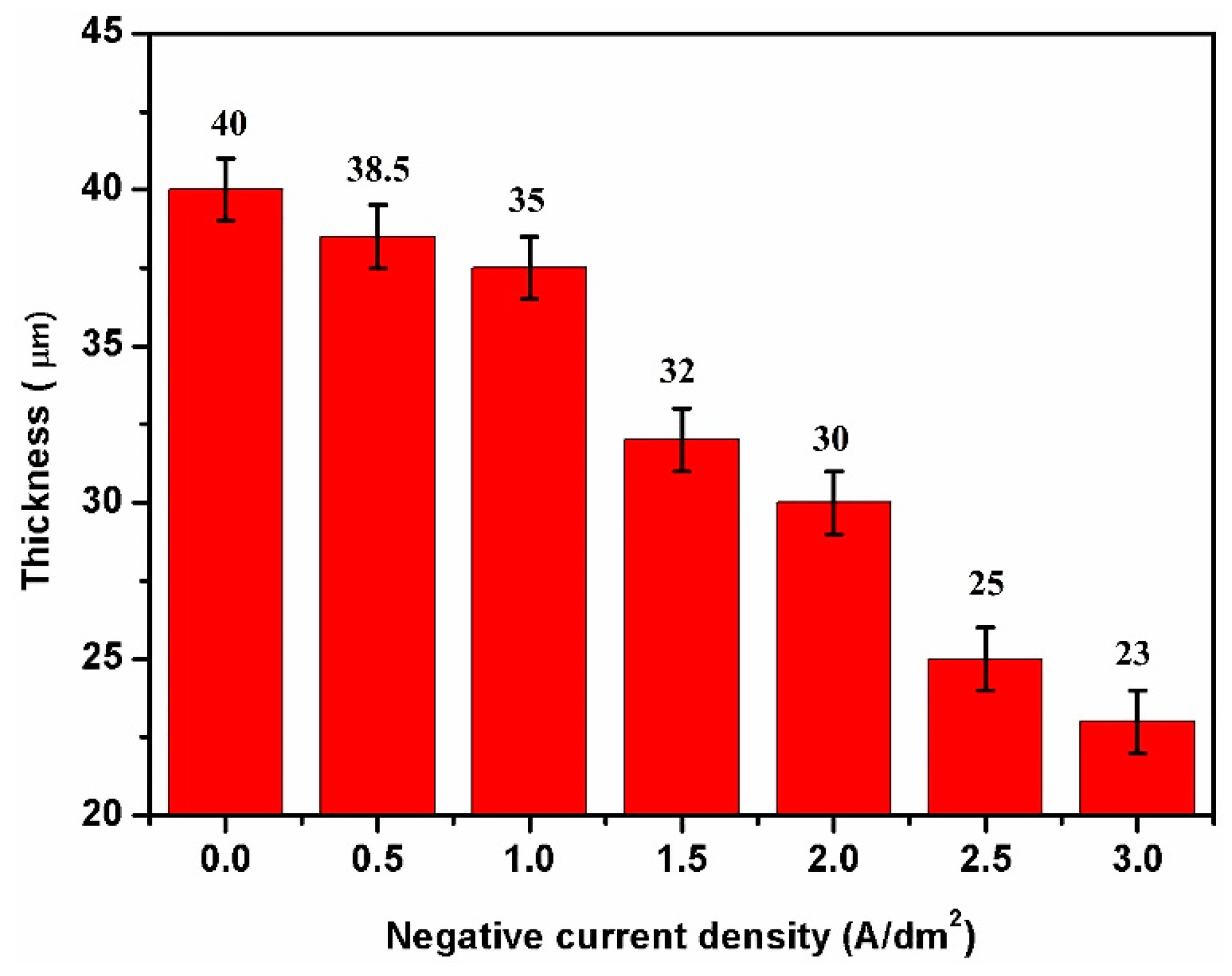
Figure 4.
Surface SEM micrographs of anodization coatings prepared at different negative current densities for 30 min: 0 A/dm2 (a,b), 1 A/dm2 (c,d), 2 A/dm2 (e,f) and 3 A/dm2 (g,h).
Figure 4.
Surface SEM micrographs of anodization coatings prepared at different negative current densities for 30 min: 0 A/dm2 (a,b), 1 A/dm2 (c,d), 2 A/dm2 (e,f) and 3 A/dm2 (g,h).

Figure 5.
Pore diameter distribution diagrams of anodization coatings prepared at different negative current densities for 30 min: 0 A/dm2 (a), 1 A/dm2 (b), 2 A/dm2 (c) and 3 A/dm2 (d).
Figure 5.
Pore diameter distribution diagrams of anodization coatings prepared at different negative current densities for 30 min: 0 A/dm2 (a), 1 A/dm2 (b), 2 A/dm2 (c) and 3 A/dm2 (d).

Figure 6.
Schematic diagram of two different current modes: (a) pulse anodization (PA) and (b) HPA.
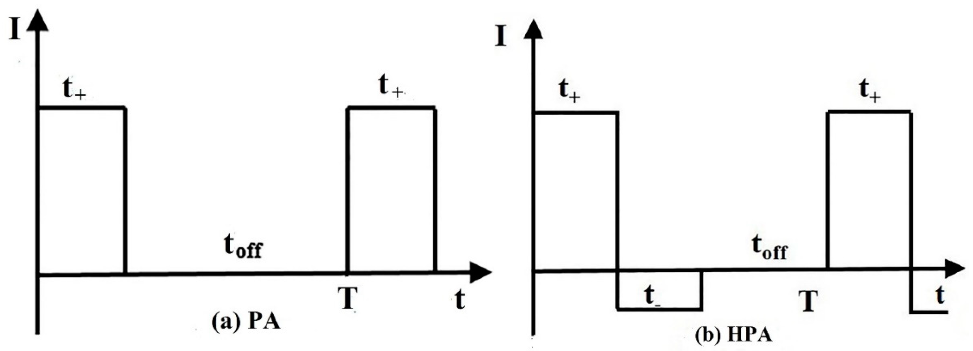
Figure 7.
Schematic diagram of ion movements and distributions during the anodization process without (a,c) and with (b,d) negative current.
Figure 7.
Schematic diagram of ion movements and distributions during the anodization process without (a,c) and with (b,d) negative current.

© 2018 by the authors. Licensee MDPI, Basel, Switzerland. This article is an open access article distributed under the terms and conditions of the Creative Commons Attribution (CC BY) license (http://creativecommons.org/licenses/by/4.0/).
Share and Cite
MDPI and ACS Style
Huang, S.; Jiang, B.; Liu, C.; Shao, Q.; Li, H. Effect of Negative Current on the Microstructure of Oxide Coatings Prepared by Hybrid Pulse Anodization. Metals 2019, 9, 22. https://doi.org/10.3390/met9010022
AMA Style
Huang S, Jiang B, Liu C, Shao Q, Li H. Effect of Negative Current on the Microstructure of Oxide Coatings Prepared by Hybrid Pulse Anodization. Metals. 2019; 9(1):22. https://doi.org/10.3390/met9010022
Chicago/Turabian StyleHuang, Shuo, Bailing Jiang, Cancan Liu, Qingying Shao, and Hongtao Li. 2019. "Effect of Negative Current on the Microstructure of Oxide Coatings Prepared by Hybrid Pulse Anodization" Metals 9, no. 1: 22. https://doi.org/10.3390/met9010022
Note that from the first issue of 2016, this journal uses article numbers instead of page numbers. See further details here.