Laboratory Experimental Setup and Research on Heat Transfer Characteristics during Secondary Cooling in Continuous Casting


1
School of Energy and Environment Engineering, University of Science and Technology Beijing, Beijing 100083, China
2
Key Laboratory of Integrated Exploitation of Bayan Obo Multi-Metal Resources, Inner Mongolia University of Science and Technology, Baotou 014010, China
*
Authors to whom correspondence should be addressed.
Metals 2019, 9(1), 61; https://doi.org/10.3390/met9010061
Submission received: 23 November 2018
/
Revised: 3 January 2019
/
Accepted: 4 January 2019
/
Published: 10 January 2019
(This article belongs to the Special Issue Continuous Casting)
Abstract
:Spray cooling is a key technology in the continuous casting process and has a marked influence on the product quality. In order to obtain the heat transfer characteristics, which are closer to the actual continuous casting to serve the design, prediction and simulation, we created an experimental laboratory setup to investigate heat transfer characteristics of air mist spray cooling during the continuous casting secondary cooling process. A 200-mm thick sample of carbon steel was heated above 1000 °C, and then cooled in a water flux range of 0.84 to 3.0 L/(m2∙s). Determination of the boundary conditions involved experimental work comprising an evaluation of the thermal history and the heat flux and heat transfer coefficient (HTC) at the casting surface using inverse heat conduction numerical schemes. The results show that the heat fluxes were characterized via boiling curves that were functions of the slab surface temperatures. The heat flux was determined to be 2.9 × 10⁵ W/m2 in the range of 1100 to 800 °C with a water flux of 2.1 L/(m2∙s). The critical heat flux increased with the increase of water flux. The HTC was close to a linear function of water flux. We also obtained the relation between the HTC and the water flux in the transition boiling region for surface temperatures of 850 to 950 °C.
1. Introduction
In continuous casting, molten steel is poured from a tundish into a water-cooled mould and a partially solidified billet or slab is withdrawn from the bottom of the mould. The billet or slab is then cooled by a water spray (this is the secondary cooling process) so that the solidified billet or slab is produced constantly and continuously. Continuous casting is a bridge between steelmaking and rolling. Secondary cooling is an essential part of continuous casting and can strongly influence the quality of billets or slabs. The cooling must be controlled relative to the casting speed to avoid the formation of internal and surface cracks.
Steel solidification behavior is influenced by heat transportation under the specific cooling conditions. In the secondary cooling zone, the heat transfer behavior of the billet or slab surface is directly linked to the characteristics of the spray. These can be manipulated to control the solidification process, and in turn the billet or slab quality and the casting productivity. In an attempt to meet high billet or slab quality requirements, heat transfer in the mould and the secondary cooling have received much research attention. Due to requirements for high quality, the secondary cooling technology of continuous casting has been developed with specially designed nozzles, finer waterway control, and a more effective water injection strategy.
In recent years, numerical simulation has been widely applied to design and optimize the secondary cooling process. An accurate simulation, however, is strongly dependent on the level of understanding of the physical mechanism of the casting process, the high-temperature properties of the material involved, and thermal boundary conditions. Laboratory experiments can provide a database that can be used to specify the boundary conditions in mathematical models of secondary cooling. Thermal boundary conditions that characterize the boiling heat transfer in secondary cooling are applicable for industrial processes after validation with reliable experiments.
Important work on spray cooling can be found in the literature [1,2,3,4,5,6]. The main cooling effect derives from evaporation. Heat transfer is influenced by water flow, droplet size, and velocity. Most studies either focused on the macroscopic effect of the sprays on the heat transfer rate or attempted to characterize the heat transfer processes during the impact of the spray on a surface. Many efforts have been made to understand the effect of changing the magnitude of the heat flux or the heat transfer coefficient (HTC) in different boiling heat transfer regimes. Thomas et al. [7,8] carried out laboratory measurements of water flow and heat transfer during spray cooling. Their research focused on the conditions of the surface of the steel strand in the secondary spray cooling zones with water jet–air mist cooling. The steel surface temperature range was 1200 °C to 200 °C. Ramstorfer et al. [9] developed a dynamic spray cooling experimental platform where they measured the HTCs due to spray cooling using an experimental setup, allowing spray cooling up to a surface temperature of 1250 °C. Horský et al. [10] developed experimental methods and numerical models for spray-cooled surface heat transfer. Those papers discussed heat transfer during spray cooling and optimization of the cooling process. Ito et al. [11] also investigated the effects of the hydraulic pressure and water flow rate of a cooling water spray on cooling intensity and developed a more efficient secondary cooling system with a high-pressure water spray. Tsutsumi et al. [12] did laboratory experiments on the cooling capacities of hydraulic and mist spray cooling by several kinds of spray nozzles. They proposed an equation for HTC that considered the spray thickness and collision pressure. El-Bealy [13] studied the degree to which homogeneity of cooling conditions with air mist nozzles improved slab quality. The Brno University of Technology Heat Transfer and Fluid Flow Laboratory [14] established reliable techniques to measure the effects of individual nozzles and combinations of nozzles to determine the HTCs. They also discussed methods for determining the HTCs and using them in a solidification model.
Most industrial spray nozzles are polydispersed, which allows them to generate water droplets with a wide range of sizes and velocities. This, in addition to the complex interaction of spray droplets, makes it difficult to predict (by single or multiple sprays) the performance of an industrial spray nozzle. Extensive laboratory studies have been done on the heat transfer of drops and sprays at low mass flux or for a single spray nozzle. However, data on industrial spray nozzles with high mass flux or on multiple spray nozzles are very scarce. Meanwhile, thinner samples with short cooling times are used in laboratory studies, which have led to a measured data shortage in high-temperature ranges. Due to fewer measurement data, the measurement error has become larger. It has become essential to use thicker samples and closer to the actual billet or slab. Experiments closely emulating the actual process of secondary cooling in continuous casting are particularly important.
In the paper, we developed a multifunctional experimental setup, enabling a quantitative understanding of the secondary cooling of a continuous casting. The objective was to explore and obtain data that characterized heat transfer at high temperatures using multiple air mist spray nozzles. The calculated temperature profile, heat flux and HTCs provided insight and useful data for the development of cooling strategies for continuous casting.
2. Establishing the Experimental Setup
Compared with industrial secondary cooling of continuous casting, a laboratory-scale simulator is cost effective because it is not necessary to interrupt actual steel production. The laboratory simulator provides more flexibility to change the range of operational parameters required for optimizing the secondary cooling process and developing new continuous casting technologies. By separating the secondary cooling from the casting in the experimental setup, we avoid the operational risk associated with using liquid metal. This enables us to simulate air-mist spray cooling in the secondary cooling process.
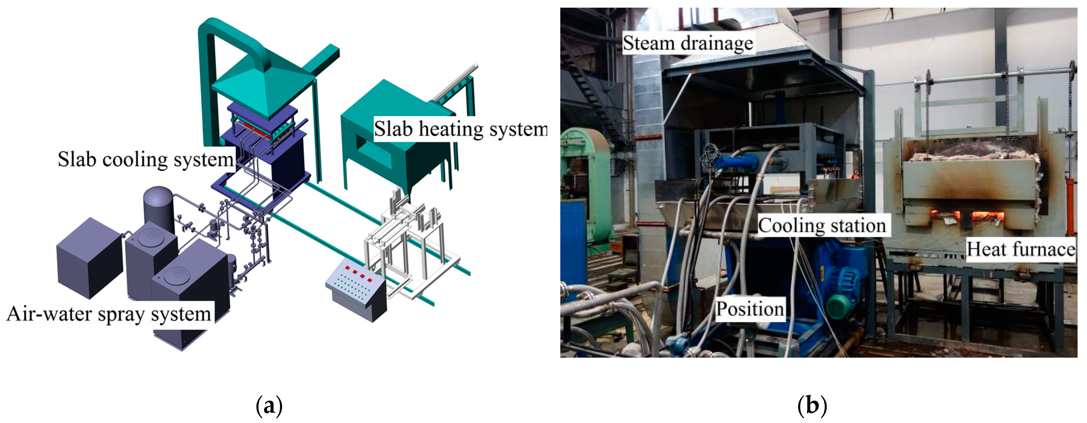
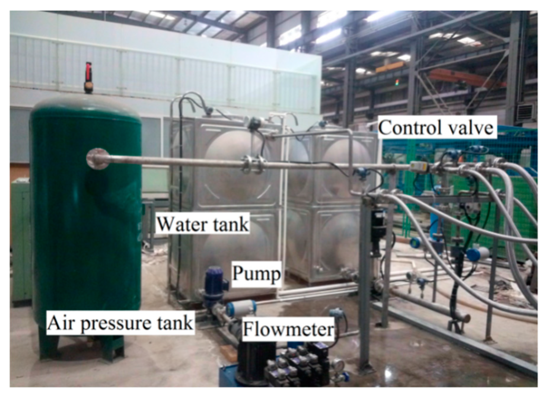
An overview of the system configuration is shown in Figure 1a,b. The experimental setup consisted of an air–water spray, slab heating, slab cooling and data acquisition and analysis systems. To simulate the features of an industrial air mist spray, a laboratory air–water spray system was designed, as shown in Figure 2. The system consisted of water tanks, pumps, an air compressor, an air pressure tank, electromagnetic flowmeters, temperature transmitters, pressure transmitters, electric control valves, metal hoses and spray racks.
Cooling water was supplied to the setup from the water tank. A valve was used to adjust the flow to the desired flowrate and pressure. The flow parameters were measured with the flowmeters and pressure gauges, which were controlled by the control software.
Nozzle alignments and cooling parameters are the main factors influencing the secondary cooling of continuous casting. The experimental setup was designed to meet the requirements of different nozzles with an extensive range of mass fluxes. The system could be adjusted to test the cooling effects of different spray configurations. The slab heating system comprised a feeding car, a heating furnace and a discharging electric actuator. After the desired temperature was reached, the slab was transported into the cooling station by a rack and pinion structure actuated by a motor. The slab cooling system included the cooling station, a slab depressing device, a reciprocating motion device, a drainage pipe, water pumps, electromagnetic flowmeters and the steam drainage system. It enabled spray rack replacement, slab movement simulation, adjustment of the slab cooling angle, and water and vapor discharge. Depending on the dynamic adjustment of the slab position by hydraulic pressure, it was possible to continuously simulate the position of the slab throughout the entire secondary cooling zone. The cooling station was placed in the positioner with 0° to 90° tilting to meet the slab arc change from initial mould position to final level position.
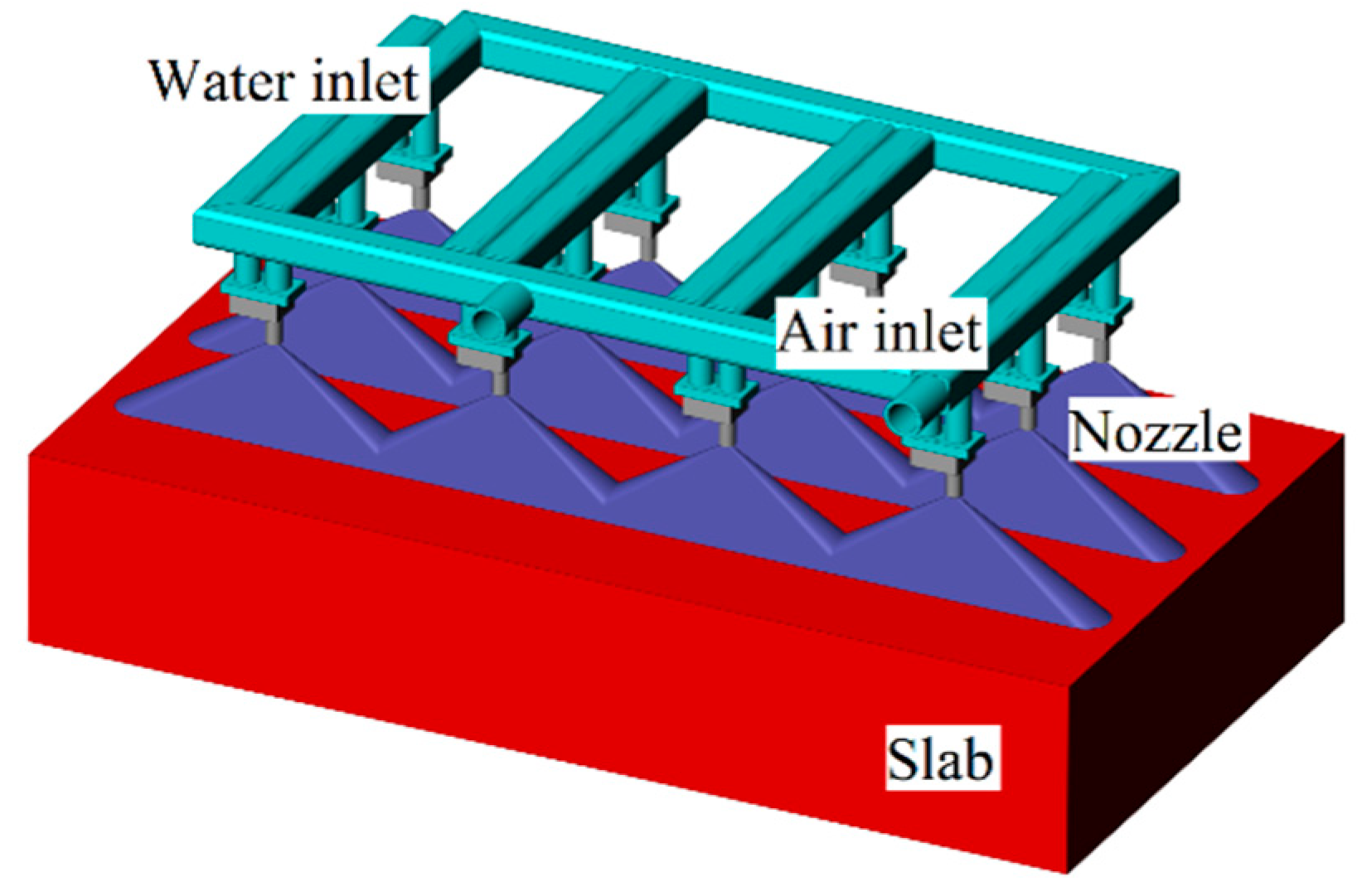
Figure 3 shows the top side cooling device that used three rows and four columns of nozzles with a 120° impingement angle. According to the nozzle angle, the overlap between the two nozzles was designed with nozzle manufacturer’s suggestion. The jets coalesced into a mist curtain on the slab surface.
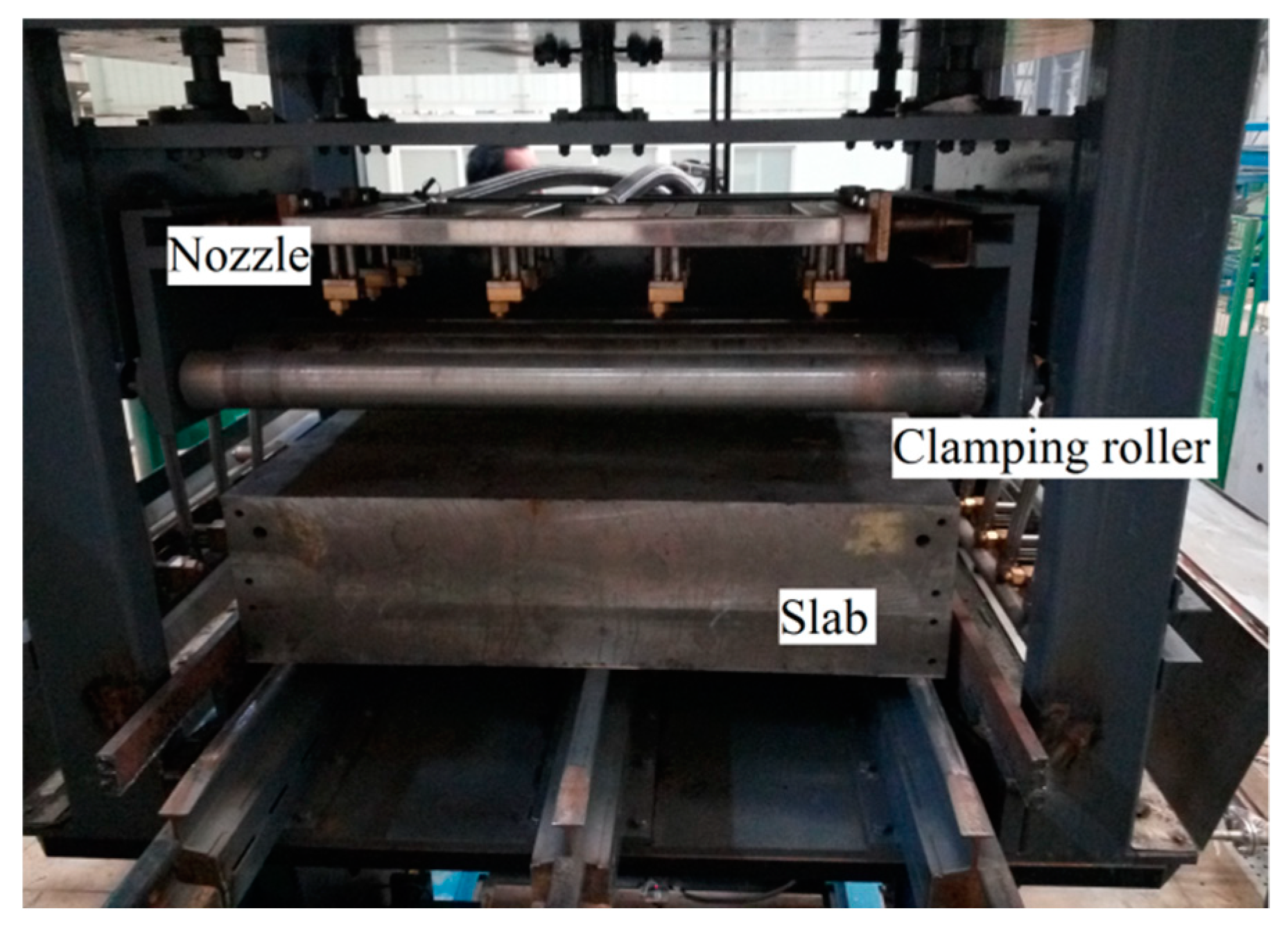
In this way, the slab contact conditions (e.g., surface structure and clamping roller) could be manipulated to be similar to those used in industrial practice. There were four clamping rollers with a 120-mm diameter and a 160-mm separation distance that could clamp a slab with a 100- to 350-mm thickness.
Figure 4 shows the clamping rollers with the top spray configuration. During the tests, the slab surface was exposed to the air mist nozzles through the gap between the rollers. The heat was conducted to the slab surface and removed by the cooling air and water. The cooling process consumed much water and air, and heat was released during the process. Vapor and cooling water were collected and directed into a drain while the apparatus operated.
A data acquisition system was used to monitor the temperature, pressure, flow rate, and so forth during heating and cooling. It comprised a computer, a data acquisition box, K-type thermocouples and a software package, which were used for process parameter acquisition, calculation and data display. The thermocouples were inserted into the subsurfaces of the slabs. The slabs were then preheated to a desired initial temperature and transported to the cooling system. The measured temperature was used as an input for calculating the inverse heat conduction. By using the calculated results, we could evaluate the local heat flux at the boundaries. The heat flux was expressed via a boiling curve with different variables. The experimental setup provided the flexibility to adjust the operational parameters (mass flux, heating temperature, casting speed, etc.), enabling study of the heat transfer in secondary cooling. The technical parameters of the setup are shown in Table 1.
3. Inverse Heat Conduction Problem
Normally, it is difficult to measure surface heat flux and temperature of a slab undergoing air mist spray cooling. When thermocouples are set at a certain distance from the surface of the slab to measure temperatures at different positions, a mathematical model can be used to calculate the surface heat flux and surface temperature [15,16]. The heat boundary condition can be calculated by recording the temperature as a function of time, which is in the form of an inverse heat transfer problem [17].
We used thermocouples embedded in the slab at certain depths to measure cooling curves at different positions. The surface temperature and heat flux of the slab were calculated using the Beck’s sequential function specification method [18,19]. As a result of the calculation, the relation between the HTC and the slab surface temperature could be obtained. In this study, we regarded the internal heat transfer in the slab as one-dimensional unsteady heat conduction along the direction of the spray cooling, ignoring the heat loss from the side of the slab. Figure 5 shows the physical model of the inverse heat conduction problem during the cooling.
The slab was heated to T0 and cooled by the heat flux q(t). A thermocouple was embedded at x = δ to record the temperature history at a time interval of Δt. The aim was to calculate q(t) using the measured temperature data with known initial conditions and the thermophysical properties of the materials involved in the system. The governing equation and boundary conditions were
where ρ is the slab density, δ is the distance between the outer surface of the slab and the thermocouple, k is the conductivity, T is the slab temperature, T0 is the initial slab temperature, Cp is heat capacity, x is the thickness direction coordinate, and Y(t) is the measured temperature. In the model, T0 and Y(t) were known; only the surface heat flux q(t) had to be solved. Since air mist cooling is a transient process, the temperature field and the heat flux qM at a certain time tM can be solved for if the temperature field TM−1(x) and the heat flux qM−1 at tM−1 have been determined. Assuming q(t) = qM, which is constant when tM−1 < t < tM, Equation (1) can be modified as Equation (2):
In this work, a sensitivity coefficient was introduced to evaluate the sensitivity of the measured temperature point error. In Beck’s method, the heat flux q(t), is discretized into a series of qi over a measurement interval Δt. The heat flux guess is kept constant within a period of time, rΔt, where r is the number of future time steps. Solved as a forward heat conduction problem, the predicted temperature by using the applied heat flux guess qi can be obtained at t = i + rΔt. In this way, the value of qi in each time interval can be found to minimize the difference between the measured and calculated temperatures. The surface heat flux at different times is therefore calculated by defining the least squares error function. A program was written in Fortran to solve the one-dimensional transient heat conduction problem. In the process of calculation, the measurement interval Δt was 0.25 s, and the number of future time steps r was 10. Thermocouples were embedded at x = 20 mm to record the temperature history. The thermal properties of the materials used in the calculation were functions of temperature and are shown in Table A1. In the course of calculation, it was considered that the steel density 7850 Kg/m3 was constant. After programming, one of the parameters about the number of mesh points needed to be tested to investigate the grid independence of the results. When the number of mesh points was greater than 400, the results do not change. The number of mesh points used in this paper was 1000.
4. Experimental Results and Discussion
One of the goals of the setup was to obtain experimental data under industrial heat flux boundary conditions for describing the boiling heat transfer in the secondary cooling of continuous casting. Precise temperature measurement was a key for a reliable heat transfer measurement [20]. Several 8-mm diameter holes were drilled 180 mm deep from the side of the 200-mm-thick slab perpendicular to the casting direction. The holes were drilled with flat bottoms to ensure that the tips of the thermocouples could touch the bottoms of the holes. A short distance from the cooling surface to the holes was required to reduce the time delay as the thermocouples responded to the changes in surface heat flux. In this experiment, the thermocouples were inserted 20 mm from the cooling surface. The thermocouples’ fastening devices were welded to the surface of the slab to push the thermocouples’ tips into contact with the bottoms of the holes. The gaps in the holes were filled with refractory cotton.
Figure 6 shows the armored K-type thermocouples that were inserted into the holes and “locked” inside by fastening devices. The locations of thermocouples numbered 1 to 5 are also shown in the figure. The thermocouples were far away from the edge of the slab to ensure a reduced heat loss effect. The thermocouple NO.1 and NO.3 were arranged inside the slab under the clamping roller respectively. The NO.2 was in the middle of the two clamping rollers. The slab was tilted 15° from the horizontal position to simulate the slab position.
The air mist spray characteristics, such as water distribution profiles, droplet velocity and the Sauer mean diameter, had an effect on heat transfer. These parameters depended on atomization and gas-water parameters of the nozzle. The main experiment parameters are shown in Table 2. Due to the swing of the spray cooling racks and the overlapping between the nozzles, the uniformity of the water distribution in the vertical and horizontal casting direction was guaranteed. It could be considered that the slab surface cooling was homogeneous. The paper focused on the average convection heat transfer coefficient in secondary cooling. The average water flux was defined as a ratio of water flow to the area of the cooling surface of the slab. The water flux was 0.84 to 3.0 L/(m2∙s) in the experiment. The nozzle arrangements with three rows and four columns were derived from the industrial continuous casting in this paper. The experimental nozzle model used was HPZ5.0-120B2.
Figure 7. shows a typical slab cooling in the experiment setup for a top spray configuration at a water temperature of 15.2 °C. Clearly, much vapor was generated during cooling, and the slab was cooled from the surface.
Typical temperature readings relative to time curves during the spray cooling are shown in Figure 8. Regardless of the thermocouple location, the time–temperature curves were similar. A high cooling rate was observed, and the slab temperature dropped drastically. Due to the strong relation between the heat flux and the surface temperature, heat extraction rates changed rapidly with time.
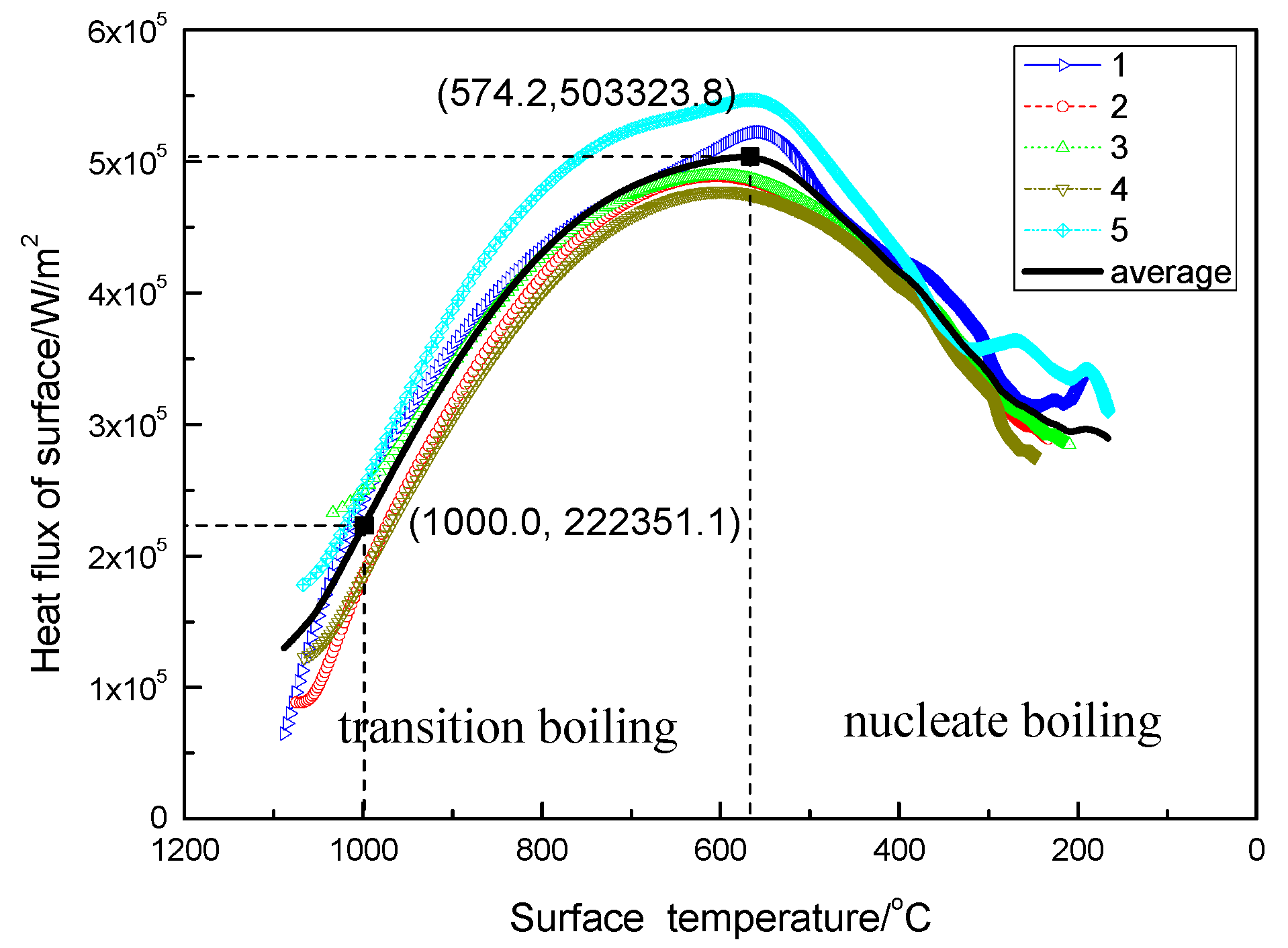
The inverse heat transfer algorithm was applied to calculate heat fluxes by using the measured temperature profile data. The calculated heat fluxes were plotted as functions of surface temperatures at each thermocouple location to determine the boiling curve.
Figure 9 shows the relation between the surface temperature and the heat flux at different measuring positions. It can be seen that the heat flux was not linearly related to the surface temperature. The five thermocouples’ average heat flux of the slab first increased to a maximum value when the slab was cooled to approximately 574.2 °C, and then decreased from the peak value with further cooling. The maximum average heat flux was 5.0 × 10⁵ W/m2 at 572.4 °C. At 1000 °C, the average heat flux was 2.2 × 10⁵ W/m2. In the temperature range from 1100 to 800 °C, the average heat flux was 2.9 × 10⁵ W/m2. Comparing the heat flux at the different thermocouple positions, better vapor discharge conditions resulted in faster cooling and a higher heat flux.
As the simulated casting speed was 1.8 m/min, all thermocouples areas were cooled by sprays and support rolls. Each thermocouple reflected the average heat transfer on the surface. The NO.5 thermocouple was located in the lower part of the sample. Good steam exhaust conditions resulted in the greater heat flux.
The surface temperature history experienced two distinct regimes. The boiling curve allowed a better understanding of the physical state of the surface [21]. The first turn in the curve coincided with the starting time of the spray cooling, from radiation to transition boiling. The second turn coincided with the critical heat flux (CHF), from transition boiling to nucleate boiling. At high surface temperatures, where film boiling was dominant, a vapor film near the solid hot surface minimized direct droplet contact time with the surface, resulting in a low heat-transfer rate. As the surface temperature decreased, the droplets began to penetrate the vapor film, and a sharp increase in the heat transfer rate was observed. After reaching the CHF, the heat flux decreased, going through the nucleate boiling regime and finally to convection or one-phase cooling.
The air mist spray heat transfer curve was similar to that of pool boiling in all the boiling regimes. However, we found that the cooling curve did not experience the Leidenfrost point due to the absence of stable film boiling. This can be explained by the following four circumstances. First, the distance between the thermocouple and the cooled surface was 20 mm, the thermocouple’s measurement delay resulted in the experiment not showing any Leidenfrost temperature. Second, the air and water flow rate are high in industrial conditions, but the residence time was short in the high-temperature region under experiment conditions. Therefore, the temperature point of Leidenfrost was not obvious. Third, the liquid droplets on the slab did not form a layer under the air mist spray cooling because the spray carried substantial momentum, which pushed the residual droplets away [22]. Fourth, the cooling steel surface oxidized, forming an oxide layer that increased the slab roughness. The oxidation of the surface had the effect of raising the gasification nucleation number.
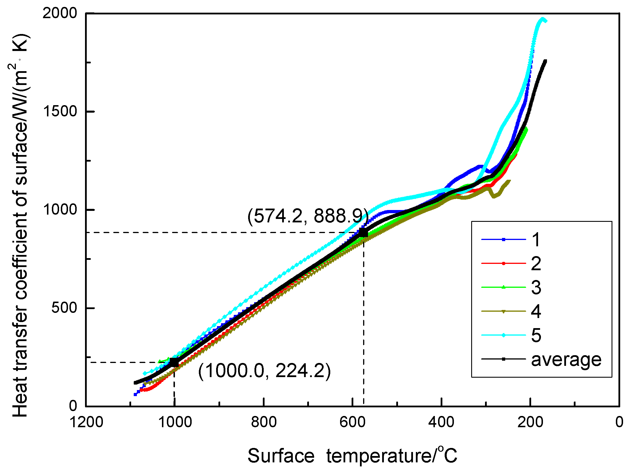
Figure 10 shows the relation between surface temperature and HTC. It could be seen that the HTC linearly varies with the temperature from 1100 to 500 °C. As temperatures decreased from 1100 to 800 °C, the average HTC linearly increased from 120.0 W/m2∙K to 542.6 W/m2∙K. At a CHF temperature of 574.2 °C, the average HTC was 888.9 W/m2∙K.
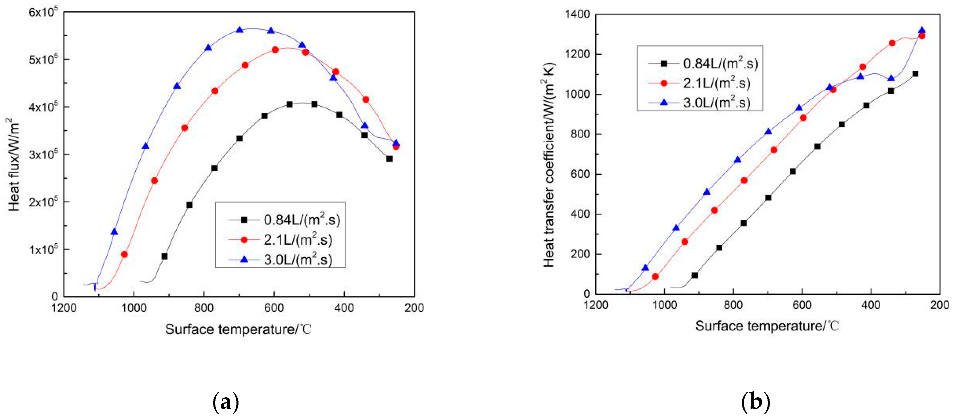
Using the method developed by this paper, we measured the heat transfer boiling curve of another condition with water fluxes of 0.84 L/(m2∙s) and 3.0 L/(m2∙s). The effect of the cooling water flux was assessed by comparing the heat transfer characteristics of the tests.
Similar slopes for the transition boiling and nucleate boiling regime were observed for different water fluxes during cooling and shown in Figure 11a. The HTC curve showed a typical linear relation, as shown in Figure 11b. The heat flux with a water flux of 3.0 L/(m2∙s) was higher, especially the CHF. There was a clear trend of increased CHF with water flux. Higher water flux led to more droplets breaking the vapor film and accelerating the steam discharge, strengthening the heat transfer on the slab surface.
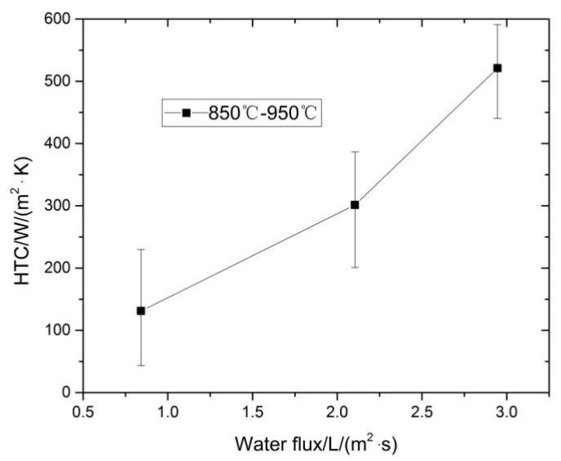
The HTC as a function of the temperature difference between the steel surface and the water flux was found to be particularly useful to apply to the solidification model, as shown in Figure 12. We concluded that the HTC was a close linear function of water mass flux for surface temperatures of 850 to 950 °C. The integrated HTC for the section can be described by the generic equation HTC = aGb, where a and b are constants determined experimentally. The following relation for heat transfer in the transition film boiling region for surface temperatures of 850 to 950 °C is suggested:
- HTC = 152 × G1.06 (W/m2∙K), where 0.84 ≤ G ≤ 3.0 (L/m2∙s)
HTC indicated the heat transfer efficiency between the surface of slab and cooling water, and the effect of heat transfer was high when HTC was large. In general, it needed to be measured by experiment and statistics, and expressed by empirical formula. Significant work regarding spray cooling could be found in the literature. Most researchers studied the macroscopic heat transfer rate. Different researchers had given different empirical formulas according to the test conditions and these formulas had different forms. Gan [23] summarized some of the formula as follows:
- HTC = 360 × G0.556, where 0.8 < G <2.5 (L/m2∙s), 727 °C < Ts < 1027 °C
- HTC = 423 × G0.556, where 1 < G < 7 (L/m2∙s), 627 °C < Ts < 927 °C
- HTC = 581G0.451 (1 − 0.0075Tw), where Tw is the water temperature
- HTC = α(708G0.75Ts−1.2 + 0.116), where α is a calibration factor, Ts is the slab temperature
- HTC = 157G0.55(1 − 0.0075Tw), where Tw is the water temperature
- HTC = 130 + 350G
Compared with the formula in the paper, there were some differences between the researches. In some cases, the difference was striking. HTC was related to the factors of water flux, spray pressure, spray distance, nozzle structure, surface temperature of slab, water temperature etc. All of these factors had an impact on the relation.
An optimized transition boiling can help to improve heat transfer for specific spray characteristics. The test model was for carbon steel, but the results equally apply to other materials [24]. However, deviations should be expected due to the surface characteristics of the spray-cooled surface [25].
In summary, heat flux and HTC are critical for the theoretical heat design of an industrial process. The experimental setup provides a powerful tool for a quantitative understanding of the heat transportation phenomena of not only continuous casting but also other industries.
5. Conclusions
In this work, an experimental setup to simulate the secondary cooling of continuous casting was developed. This provided a powerful tool for optimizing the continuous casting operation and for better continuous casting machine designs. An inverse heat conduction algorithm was used to calculate the surface heat fluxes during the slab cooling. The main conclusions derived from this study are:
- (1)
- Transition boiling was the primary heat transfer characteristic in the range from 1100 to 800 °C during secondary cooling for the continuous casting of steel.
- (2)
- In the experimental spray cooling, the average heat flux was measured to be 2.9 × 10⁵ W/m2 in the range of 1100 to 800 °C with water injection of 2.1 L/(m2∙s). The surface HTC increased linearly from 120.0 W/m2∙K to 542.6 W/m2∙K as the temperature decreased from 1100 to 800 °C.
- (3)
- The relation between HTC and water flux in the transition boiling region for surface temperatures of 850 to 950 °C was suggested to be HTC = 152 × G1.06.
Author Contributions
Conceptualization, Y.Z. and Z.W.; methodology, Y.Z., J.H. and Z.W.; formal analysis, Y.Z.; investigation, Y.Z. and J.H.; resources, Z.Z.; data curation, C.B. and Y.G.; writing—original draft preparation, Y.Z.; writing—review and editing, Z.Z.; visualization, C.B. and Y.G.; supervision, Y.Z.; project administration, J.H.; funding acquisition, Z.Z. and Z.W.
Funding
The work was supported by National Natural Science Foundation of China under Grant 51264030; National Key R & D Program of China under Grant 2016YFC0401201; and Natural Science Foundation of Inner Mongolia under Grant 2017MSLH0534.
Conflicts of Interest
The authors declare no conflicts of interest.
Appendix A

Table A1.
Thermophysical property.
| T/°C | CP/J(kg·K)−1 | k/W(m·K)−1 |
|---|---|---|
| 20 | 462 | 44.55 |
| 100 | 481 | 42.95 |
| 200 | 508 | 41.02 |
| 300 | 530 | 38.23 |
| 400 | 560 | 35.74 |
| 500 | 605 | 33.20 |
| 600 | 680 | 30.81 |
| 700 | 824 | 29.39 |
| 765 | 1360 | 38.38 |
| 800 | 718 | 25.39 |
| 900 | 615 | 26.13 |
| 1000 | 604 | 25.57 |
| 1100 | 685 | 23.71 |
| 1200 | 858 | 20.55 |
References
- Wendelstorf, J.; Spitzer, K.H.; Wendelstorf, R. Spray water cooling heat transfer at high temperatures and liquid mass fluxes. Int. J. Heat Mass Transf. 2008, 51, 4902–4910. [Google Scholar] [CrossRef]
- Petrus, B.; Zheng, K.; Zhou, X.; Thomas, B.G.; Bentsman, J. Real-Time, Model-Based Spray-Cooling Control System for Steel Continuous Casting. Metall. Mater. Trans. B 2011, 42, 87–103. [Google Scholar] [CrossRef]
- Ramstorfer, F.; Roland, J.; Chimani, C.; Mörwald, K. Investigation of Spray Cooling Heat Transfer for Continuous Slab Casting. Mater. Manuf. Process 2011, 26, 165–168. [Google Scholar] [CrossRef]
- Hauksson, A.T.; Fraser, D.; Prodanovic, V.; Samarasekera, I. Experimental study of boiling heat transfer during subcooled water jet impingement on flat steel surface. Ironmak Steelmak 2004, 31, 51–56. [Google Scholar] [CrossRef]
- Minchaca, J.I.; Castillejos, A.H.; Acosta, F.A. Size and Velocity Characteristics of Droplets Generated by Thin Steel Slab Continuous Casting Secondary Cooling Air-Mist Nozzles. Metall. Mater. Trans. B 2011, 42, 500–515. [Google Scholar] [CrossRef]
- Zhang, J.; Chen, D.F.; Zhang, C.Q.; Wang, S.G.; Hwang, W.S.; Han, M.R. Effects of an even secondary cooling mode on the temperature and stress fields of round billet continuous casting steel. J. Mater. Process. Technol. 2015, 222, 315–326. [Google Scholar] [CrossRef]
- Hernandez, C.A.; Minchaca, J.I.; Humberto, C.E.; Acosta, F.A.; Zhou, X.; Thomas, B.G. Measurement of heat flux in dense air-mist cooling: Part II—The influence of mist characteristics on steady-state heat transfer. Exp. Therm. Fluid Sci. 2013, 44, 161–173. [Google Scholar] [CrossRef]
- Hernandez, C.A.; Castillejos, A.H.; Acosta, F.A.; Zhou, X.; Thomas, B.G. Measurement of heat flux in dense air-mist cooling: Part I—A novel steady-state technique. Exp. Therm. Fluid Sci. 2013, 44, 147–160. [Google Scholar] [CrossRef]
- Ramstorfer, F.; Roland, J.; Chimani, C.; Mörwald, K. Modelling of air-mist spray cooling heat transfer for continuous slab casting. Int. J. Cast Met. Res. 2013, 22, 39–42. [Google Scholar] [CrossRef]
- Horský, J.; Raudenský, M.; Pohanka, M. Experimental Study of Heat Transfer in Hot Rolling and Continuous Casting. Mater. Sci. Forum 2005, 473–474, 347–354. [Google Scholar] [CrossRef]
- Ito, Y.; Murai, T.; Miki, Y.; Mitsuzono, M.; Goto, T. Development of Hard Secondary Cooling by High-pressure Water Spray in Continuous Casting. ISIJ Int. 2011, 51, 1454–1460. [Google Scholar] [CrossRef] [Green Version]
- Tsutsumi, K.; Kubota, J.; Hosokawa, A.; Ueoka, S.; Nakano, H.; Kuramoto, A.; Sumi, I. Effect of Spray Thickness and Collision Pressure on Spray Cooling Capacity in a Continuous Casting Process. Steel Res. Int. 2018, 89, 9. [Google Scholar] [CrossRef]
- El-Bealy, M.O. Air-Water Mist and Homogeneity Degree of Spray Cooling Zones for Improving Quality in Continuous Casting of Steel. Steel Res. Int. 2011, 82, 1187–1206. [Google Scholar] [CrossRef]
- Moravec, R.; Blazek, K.; Horsky, J.; Graham, C.; Fiegle, S.; Dombovic, T.; Kaurich, T. Coupling of Solidification model And Heat Transfer Coefficients to Have Valuable Tool for Slab Surface Temperatures Prediction. In Proceedings of the METEC 7th InSteelCon, Düsseldorf, Germany, 27 June–1 July 2011; pp. 1–9. [Google Scholar]
- Chen, L.; Askarian, S.; Mohammadzaheri, M.; Samadi, F. Simulation and Experimental study of Inverse Heat Conduction Problem. Fund. Chem. Eng. 2011, 233–235, 2820–2823. [Google Scholar] [CrossRef]
- Buczek, A.; Telejko, T. Inverse determination of boundary conditions during boiling water heat transfer in quenching operation. J. Mater. Process. Technol. 2004, 155–156, 1324–1329. [Google Scholar] [CrossRef]
- Tapaswini, S.; Chakraverty, S.; Behera, D. Numerical solution of the imprecisely defined inverse heat conduction problem. Chin. Phys. B 2015, 24, 050203. [Google Scholar] [CrossRef]
- Beck, J.V.; Blackwell, B.; St Clair, C.R. Inverse Heat Conduction, Ill-Posed Problems; John Wiley & Sons: Hoboken, NJ, USA, 1985. [Google Scholar]
- Woodbury, K.A.; Beck, J.V.; Najafi, H. Filter solution of inverse heat conduction problem using measured temperature history as remote boundary condition. Int. J. Heat Mass Trans. 2014, 72, 139–147. [Google Scholar] [CrossRef]
- Stetina, J.; Mauder, T.; Klimes, L.; Masarik, M.; Kavicka, F. Operational Experiences with the Secondary Cooling Modification of Continuous Slab Casting. In Proceedings of the Metal 2013: 22nd International Conference on Metallurgy And Materials, Brno, Czech Republic, 15–17 May 2013; pp. 62–67. [Google Scholar]
- Raudensky, M.; Horsky, J. Secondary cooling in continuous casting and Leidenfrost temperature effects. Ironmak Steelmak 2005, 32, 159–164. [Google Scholar] [CrossRef]
- Timm, W.; Weinzierl, K.; Leipertz, A. Heat transfer in subcooled jet impingement boiling at high wall temperatures. Int. J. Heat Mass Trans. 2003, 46, 1385–1393. [Google Scholar] [CrossRef]
- Gan, Y. Practical Manual for Continuous Casting; Metallurgical Industry Press: Beijing, China, 2010; pp. 68–69. ISBN 978-7-5024-5044-1. [Google Scholar]
- Fang, Q.; Ni, H.; Zhang, H.; Wang, B.; Liu, C. Numerical Study on Solidification Behavior and Structure of Continuously Cast U71Mn Steel. Metals 2017, 7, 483. [Google Scholar] [CrossRef]
- Teodori, E.; Pontes, P.; Moita, A.; Georgoulas, A.; Marengo, M.; Moreira, A. Sensible Heat Transfer during Droplet Cooling: Experimental and Numerical Analysis. Energies 2017, 10, 790. [Google Scholar] [CrossRef]
Figure 1.
Schematic presentation (a) and equipment (b) of the experimental setup.

Figure 2.
Air-water spray system.

Figure 3.
Schematic of the arrangement of the nozzles.

Figure 4.
The clamping rollers with no contact slab.

Figure 5.
Schematic of the physical model of the inverse heat conduction problem.

Figure 6.
Sketch of the locations of thermocouples.

Figure 7.
Slab cooling process.

Figure 8.
Temperature evolution during cooling at positions 1 to 5.

Figure 9.
Relationship between surface temperature and heat flux.

Figure 10.
Relationship between surface temperature and HTC.

Figure 11.
Heat characteristics with different water flux for (a) heat flux; (b) HTC.

Figure 12.
The HTC as a function of water flux.

Table 1.
Technical parameters of the pilot experimental set-up.
| Condition | Parameter |
|---|---|
| Max. heating slab size | 1100 × 600 × 350 mm(thickness) |
| Max. heating temperature | 1250 °C |
| Max. water flow | 18.0 m3/h |
| Max. air flow | 6.0 m3/min |
| Max. water pressure | 1.0 MPa |
| Max. air pressure | 0.4 MPa |
| Max. nozzle array | 3 rows and 4 columns |
| Max. temperature synchronous acquisition frequency | 5 Hz |
| Cooling condition | Single or multi-side cooling |
Table 2.
Parameters.
| Experimental Condition | Parameter Value |
|---|---|
| Slab size | 1100 × 600 × 200 mm |
| Material | ASTM A572 Gr.50 |
| Air pressure | 0.2 MPa |
| Water flux | 2.1 L/(m2∙s) |
| Nozzle distance from slab surface | 180 mm |
| Heating target temperature | 1150 °C |
| Temperature sampling frequency | 4 Hz |
| Cooling condition | Top cooling |
| Water temperature | 15.2 °C |
| Experimental nozzle model | HPZ5.0-120B2 |
© 2019 by the authors. Licensee MDPI, Basel, Switzerland. This article is an open access article distributed under the terms and conditions of the Creative Commons Attribution (CC BY) license (http://creativecommons.org/licenses/by/4.0/).
Share and Cite
MDPI and ACS Style
Zhang, Y.; Wen, Z.; Zhao, Z.; Bi, C.; Guo, Y.; Huang, J. Laboratory Experimental Setup and Research on Heat Transfer Characteristics during Secondary Cooling in Continuous Casting. Metals 2019, 9, 61. https://doi.org/10.3390/met9010061
AMA Style
Zhang Y, Wen Z, Zhao Z, Bi C, Guo Y, Huang J. Laboratory Experimental Setup and Research on Heat Transfer Characteristics during Secondary Cooling in Continuous Casting. Metals. 2019; 9(1):61. https://doi.org/10.3390/met9010061
Chicago/Turabian StyleZhang, Yazhu, Zhi Wen, Zengwu Zhao, Chunbao Bi, Yaxiang Guo, and Jun Huang. 2019. "Laboratory Experimental Setup and Research on Heat Transfer Characteristics during Secondary Cooling in Continuous Casting" Metals 9, no. 1: 61. https://doi.org/10.3390/met9010061
Note that from the first issue of 2016, this journal uses article numbers instead of page numbers. See further details here.