Numerical Simulation of Fluid Flow, Heat Transfer, Species Transfer, and Solidification in Billet Continuous Casting Mold with M-EMS

1
School of Metallurgy, Northeastern University, Shenyang 110819, China
2
Key Laboratory for Ecological Metallurgy of Multimetallic Ores (Ministry of Education), Northeastern University, Shenyang 110819, China
*
Author to whom correspondence should be addressed.
Metals 2019, 9(1), 66; https://doi.org/10.3390/met9010066
Submission received: 9 December 2018
/
Revised: 30 December 2018
/
Accepted: 7 January 2019
/
Published: 11 January 2019
(This article belongs to the Special Issue Optimization of Industrial Casting Processes)
Abstract
:Electromagnetic stirring in mold (M-EMS) has been widely used in continuous casting process to improve the solidification quality of the steel strand. In the present study, a 3D multi-physical-field mathematical model was developed to predict the macro transport phenomena in continuous casting mold with M-EMS using ANSYS commercial software, and was adopted to investigate the effect of current intensity (0, 150, 200, and 240 A) on the heat, momentum, and species transports in the billet continuous casting mold with a size of 160 mm × 160 mm. The results show that when the M-EMS is on, the horizontal swirling flow appears and shifts the high-temperature zone upward. With the increase of current intensity, two swirling flows form on the longitudinal section of continuous casting mold and become more intensive, and the flow velocity of the molten steel at the solidification front increases. Thus, the wash effects of the fluid flow on the initial solidified shell become intensive, resulting in a thinner shell thickness at the mold exit and a significant negative segregation of carbon at the billet subsurface.
1. Introduction
During the continuous casting process, the molten steel enters the mold through the submerged entry nozzle (SEN), and begins to solidify under the intensive primary cooling condition in mold. With the growth of the initial solidified shell, the solutes are rejected into the liquid at the solid/liquid interface due to the lower solubility of the solute in the solid phase, and redistribute through diffusion and mass convection induced by the fluid flow in the mold. Also, the molten steel flow in the mold can change the temperature field and affect the growth of initial solidified shell, which could enhance the equiaxed zone via the columnar (dendrites) zone erosion. Thus, the interactive effects between the fluid flow and initial solidification of molten steel in the mold are very complicated and have great effects on the strand quality [1]. Usually, in order to achieve defect-free strand and high-efficiency production, electromagnetic stirring (EMS) is widely applied to control the fluid flow, heat transport, and solidification of molten steel in a continuous casting mold [2].
Owing to the presence of high-temperature and opaque materials, it is impossible to observe the fluid flow and solidification of molten steel in situ in the continuous casting mold. Meanwhile, the trial and error method is very expensive and not well suited to systematic studies. Alternatively, the numerical simulation is an effective tool to fundamentally understand the macroscopic transport phenomena in the continuous casting mold with EMS and thus has attracted more and more attention in recent decades. In 1986, Spitzer et al. [3] first developed a three-dimensional (3D) magnetohydrodynamic (MHD) model, which involves the solution of the Maxwell equations and the turbulent Navier‒Stokes equations with k‒ε model equations. The effect of stirrer position, stirrer length, and electromagnetic parameters on the flow field in continuous casting of round strands were investigated and validated with experimental measurements. Fujisaki et al. [4,5,6,7] developed a 3D MHD model of fluid flow, heat transfer, and solidification in a continuous casting mold with M-EMS and investigated the free surface velocity of the bulk molten steel in a mold. Natarajan and El-Kaddah [8,9] proposed a fixed-grid methodology for 3D modeling of electromagnetically driven flow in continuous casting of steel using the hybrid differential‒integral formulation of the electromagnetic field. They found that a strong turbulent flow was generated in the continuous casting strand by the stirrer and the effective mixing region in the molten pool was about three times the length of the stirrer. Tallbäck et al. [10] developed an electromagnetic and flow field coupled model and predicted the angular velocity distribution in an industrial scale EMS system for billet continuous casting. Liu et al. [11] proposed a coupled 3D MHD model where the interaction between the inertial impinging jet from SEN was taken into consideration, and investigated the fluid flow in a round bloom mold with rotary M-EMS. Yu and Zhu [12] numerically simulated the effect of operation parameters of M-EMS on the magnetic field, temperature profile, and inclusion trajectories in a round billet continuous casting mold, and carried out the industrial trials to study the effect of M-EMS parameters on the solidification structure and macrosegregation in continuously cast bloom of high carbon steel. Geng et al. [13] performed numerical simulations to optimize the M-EMS parameters using a 3D mathematical model and finally determined the optimal M-EMS parameters for the round billet continuous casting by industrial trials.
All the above mentioned research works mainly focus on the effect of M-EMS on the fluid flow in the mold without considering the initial solidification, which has great effects on the fluid flow in the mold. Therefore, in order to make the simulation results more reliable, the heat transfer and solidification in the mold should be taken into consideration in modeling. Yang et al. [14] developed a coupled model of fluid flow and solidification in bloom continuous casting mold with M-EMS and indicated that the optimal current intensity and frequency of M-EMS were respectively 300 A and 3 Hz for the 260 mm × 300 mm bloom of bearing steel. Jiang and Zhu [15] flexibly adopted different empirical formulations to determine the permeability in the solidification model in terms of solidification structure morphology and investigated the flow and solidification behavior in billet continuous casting process with EMS. Ren et al. [16,17] proposed a 3D weakly coupled mathematic model to study to the electromagnetic field, fluid flow, heat transfer and solidification in continuous casting mold and indicated that the swirl flow velocity decreased remarkably when solidification is considered. Trindade et al. [18] investigated the solidification in the round billet continuous casting mold with M-EMS using the 3D coupled model of fluid flow, heat transfer and solidification, and concluded that a thinner shell close to the stirrer center and larger region of solid fraction in the billet center were produced by M-EMS. Dong et al. [19] developed a 3D MHD model considering flow field and solidification in mold and investigated the interactive effect of fluid flow and magnetic field in the billet continuous casting mold. Maurya and Jha [20] numerically studied the effect of M-EMS position on fluid flow and solidification in a billet continuous casting mold and indicated that the stirrer position had a significant effect on the formation of the solidified shell. Fang et al. [21] numerically studied the effects of a SEN on flow and initial solidification in a 280 mm × 380 mm bloom continuous casting mold with EMS, and accordingly optimized the structure of SEN.
Although the solidification was taken into consideration in recently developed model, the solute transport, which is one of the key processes to characterize the macrosegregation of the strand, was usually ignored. Kang et al. [22] developed a 2D mathematical model coupling the turbulent fluid flow, heat and solute transport in a continuous slab caster with an electromagnetic brake (EMBr), and investigated the solidification and macrosegregation in continuous casting. Lei et al. [23] developed a 3D mathematical model to study the flow, solidification and solute transport in a continuous casting mold with EMBr, and concluded that the magnetic field can effectively damp the local flow and affect heat and solute transport in the mold. Sun and Zhang [24] developed a coupling electromagnetic-thermal-solute transportation model and investigated the macrosegregation in continuously cast bloom of high-carbon bearing steel GCr15 with EMS using a 3D and 2D hybrid method. Fang et al. [25] numerically investigated the fluid flow, solidification and solute transport in the bloom continuous casting with EMS and concluded that the initial solidified shell, molten steel temperature, and solute distribution in the EMS effective zone could be effectively homogenized by M-EMS.
Although significant progress has been made in developing multi-physical-field models to reveal the macro-scale transport phenomena in continuous casting mold, our understanding of the interactive effects of fluid flow, heat transfer, initial solidification, and solute distribution with M-EMS is still far from satisfactory. In the present study, a 3D multi-physical-field mathematical model was developed to predict the macro transport phenomena in continuous casting mold with M-EMS using ANSYS commercial software (ANSYS 16.0, ANSYS Inc., Pittsburgh, PA, USA), and validated by the magnetic flux density measurement in the mold with a SHT-III teslameter (HP Spinix Inc., Shenyang, China) and the carbon concentration measurement at the billet subsurface with an Infrared Carbon‒Sulfur analyzer (CS230) (LECO Inc., Saint Joseph, MI, USA) which can detect the content of carbon in steel. Then, the model was adopted to investigate the effect of current intensity (0, 150, 200, and 240 A) on heat, momentum, and species transports in the billet continuous casting mold with a size of 160 mm × 160 mm.
2. Model Descriptions
2.1. Basic Assumptions
The fluid flow in the continuous casting mold with EMS interacts with magnetic field and solidification, and thus the quantitative representation of transport phenomena in the mold, requires the coupled solution of the Navier‒Stokes equation, Maxwell’s equation, heat transfer equations of solidification, and the solute transport equation. In order to reduce the complexity of the coupled model and improve computational efficiency, the following assumptions are made:
- (1)
- Owing to the small magnetic Reynolds number (about 0.01) of M-EMS, the effect of fluid flow on the electromagnetic field is ignored and the electromagnetic field is assumed to be quasi-static due to the low stirring current frequency adopted in M-EMS.
- (2)
- Compared with the latent heat released during the solidification process of Fe‒C alloy, the Joule heating generated by the induced current is very small and thus ignored in the modeling.
- (3)
- The molten steel is assumed to be a Newtonian incompressible fluid with constant thermophysical parameters, such as density, viscosity, thermal conductivity, and specific heat.
- (4)
- Local thermodynamic equilibrium at the solid/liquid interface is assumed to be achieved during the solidification process.
- (5)
- The mold and strand are assumed to be vertical, and mold taper and oscillation are ignored.
- (6)
- The meniscus is assumed to be flat and the top molten slag is ignored.
2.2. Governing Equations
2.2.1. Electromagnetic Field Model
The function of electromagnetic stirrer is to generate Lorentz force in molten steel and produce a rotational flow in mold. The electromagnetic field can be calculated by Maxwell’s equations:
Ampere’s law:
Faraday’s law:
Gauss’s law:
Gauss’s law for magnetism:
Ohm’s law:
where H is the magnetic field, J is the current intensity, E is the electric field, B is the magnetic flux density, D is the electric flux density, q is the electric charge density, σ is the electric conductivity, and t is the time.
The time-averaged electromagnetic force, Fm, resulting from the interaction between electric current and magnetic field can be determined by
where Re represents the real part of a complex number.
2.2.2. Fluid Flow Model
The melt flow pattern in the mold is described by the continuity and momentum equations under turbulent conditions:
where U is the flow velocity, ρ is the density, μl is the laminar viscosity, μt is the turbulent viscosity, P is the static pressure, Sp is the momentum sink, Fm is the electromagnetic force, and Fb is the thermosolutal buoyancy. The momentum sink accounts for the phase interaction force in the mushy zone, and can be described as follows:
The thermosolutal buoyancy consists of thermal and solutal buoyancy, which are induced by the temperature and solutal gradient. According to the Boussinesq approximation [26], the density depends linearly on the temperature and solute concentration, and appears only in the buoyancy term of the momentum equation. So, the thermosolutal buoyancy can be determined by
where fl is the liquid fraction, ξ is a very small positive number, Us is the velocity of solid phase, g is the gravitational acceleration, T is the temperature, Tref is the reference temperature, which is defined as liquidus temperature, βt is the thermal expansion coefficient, Cl,i is the solute concentration of element i in liquid phase, Cref,i is the reference solute concentration of element i, which is defined as the initial concentration value of element i, βc,i is the solutal expansion coefficient of element i, N is the total number of solute elements in the commercial steel, Amush is a mushy zone constant that depends on the grain structure morphology, and Amush can be written as:
where μl is set to be 0.0062 kg m−1 s−1, K0 is given as follows:
where λ2 is the secondary dendrite arm spacing, and the value is 10−4 m. In the present research, the value of Amush is set to 1 × 10⁸.
To consider the effects of turbulence on the fluid flow in mold, the standard two-equation k–ε model is used here. The turbulence kinetic energy, k, and its rate of dissipation, ε, are given as follows:
where Gk represents the generation of turbulence kinetic energy due to the mean velocity gradients, Gb is the generation of turbulence kinetic energy due to buoyancy, μt is the turbulent viscosity, C1ε, C2ε, C3ε and Cμ are constants, σk and σε are respectively the turbulent Prandtl numbers for k and ε. The recommended values for C1ε, C2ε, Cμ, σk, and σε are, respectively, 1.44, 1.92, 0.09, 1.0, and 1.3 [27]. Sk and Sε are source terms, which are adopted to take the effects of the porous material into consideration, and can be expressed as follows:
Sink are added to all turbulence equations in the mushy zone and solidified zones to take into account the solid material presence, where , the turbulence quantity, being solved(k, ε).
2.2.3. Heat-Transfer and Solidification Model
Both the sensible and latent heat of molten steel are extracted by the cooling water and finally the molten steel is gradually solidified into a strand with a preset shape during the continuous casting process. The energy conservation equation can be described as follows:
where keff is the effective thermal conductivity, T is the temperature, and H is the total enthalpy, expressed as follows:
where href is the reference enthalpy, cp is the specific heat, and L is the latent heat. The liquid fraction, fl, is determined by the lever rule and given as follows:
where fs is the solid fraction, Tl and Ts are the liquidus and solidus temperature, respectively, obtained by
where mi is the liquidus slope in the Fe-i binary phase diagram, and ki is the equilibrium partition coefficient of solute element i.
2.2.4. Species Transfer Model
During the continuous casting process of steel, the solute is rejected at the liquid/solid interface and redistributes under the effects of the Fickian diffusion, convection, and phase transport. The solute distribution in the strand can be determined by the solute conservation equation:
where Dl,i and Ds,i are, respectively, the solute diffusion coefficient of element i in liquid and solid phase; Sct is the turbulent Schmidt numbers and its recommended value is 1.0; Ci, Cl,i, and Cs,i are, respectively, the solute concentration of element i in control volume, liquid, and solid phase. According to the mixture theory, the relationship of Ci, Cl,i and Cs,i is given by the following equation:
2.3. Boundary Conditions
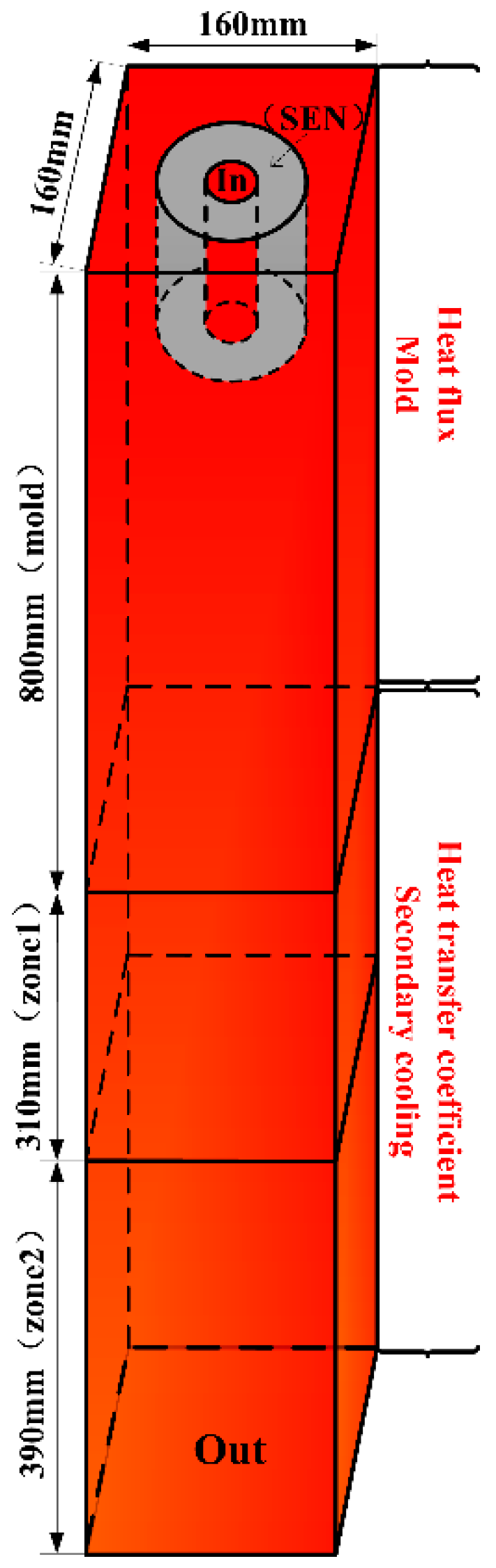
The boundary conditions of the present 3D mathematical model are schematically shown in Figure 1, and the comprehensive description of the boundary conditions for electromagnetic field, fluid flow, heat transfer, solidification, and solute transport is given as follows.
2.3.1. Electromagnetic Field
The magnetic stirrer is applied with three-phase coil excitation to create a rotating magnetic field and assumed to be enclosed by an air cylinder. The magnetic flux is assumed to be parallel to the lateral side of the air cylinder, and the Neumann boundary conditions are applied at both the top and bottom surface.
2.3.2. Fluid Flow
The inlet is located on the top of SEN and the inlet velocity is calculated based on the mass conservation in the system. The turbulence parameters at the SEN inlet are calculated by the semi-empirical equation [28]. A zero shear stress condition is applied at the meniscus and zero normal gradient of velocity is used at the outlet. The velocity of strand wall is specified as the casting speed.
2.3.3. Heat Transfer and Solidification
The inlet temperature is specified as the sum of liquidus temperature and superheat, and the top surface of molten steel is assumed to be adiabatic. The heat transfer of strand wall mainly dependents on the strand location and is comprehensively described in our previous work [29].
2.3.4. Species Transfer
The solute concentration at the inlet is given by the nominal composition of steel, and zero normal gradient of solute concentration is used at the outlet. The zero flux of solute diffusion is applied both at the strand wall and free surface.
3. Numerical Simulation Description
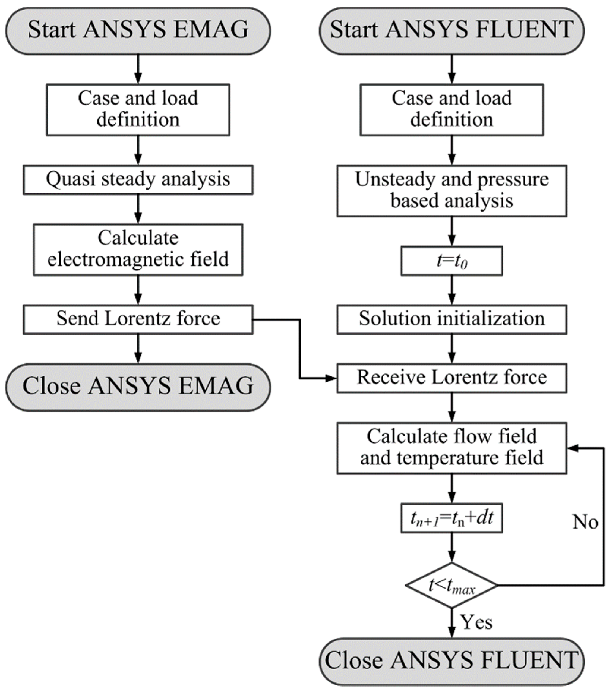
Figure 2 shows the flowchart of the present 3D coupled model for the predication of multi-physical field in the continuous casting mold with M-EMS. In order to achieve the coupled simulation of electromagnetic field, fluid flow, and heat and solute transport, the simulation of electromagnetic field in the continuous casting mold with M-EMS is carried out using the commercial software ANSYS EMAG(ANSYS 16.0, ANSYS Inc., Pittsburgh, PA, USA), and then the electromagnetic force is introduced into the momentum equation as an additional source via the User-Defined Functions (UDF) of the commercial software ANSYS FLUENT(ANSYS 16.0, ANSYS Inc., Pittsburgh, PA, USA). The Maxwell’s equations are solved with the magnetic vector potential to predict the electromagnetic field in the continuous casting mold. The flow, temperature, and solute field in the continuously cast billet are calculated by solving the turbulent Navier‒Stokes equation, energy equation, and mass conservation equation. Moreover, an enthalpy–porosity technique is adopted to predict the solidification of molten steel during the continuous casting process. It should be mentioned here that the transient calculations are performed to predict the multi-physical-field in the continuous casting mold with M-EMS, and the total calculation time is large enough to make the fluid flow, heat transfer, and solute transport steady. The low-carbon steel 20CrMnTi is used in this study, and the chemical compositions, detailed process parameters, and physical properties of steel used in the present study are listed in Table 1 and Table 2.
4. Results and Discussion
4.1. Model Validation
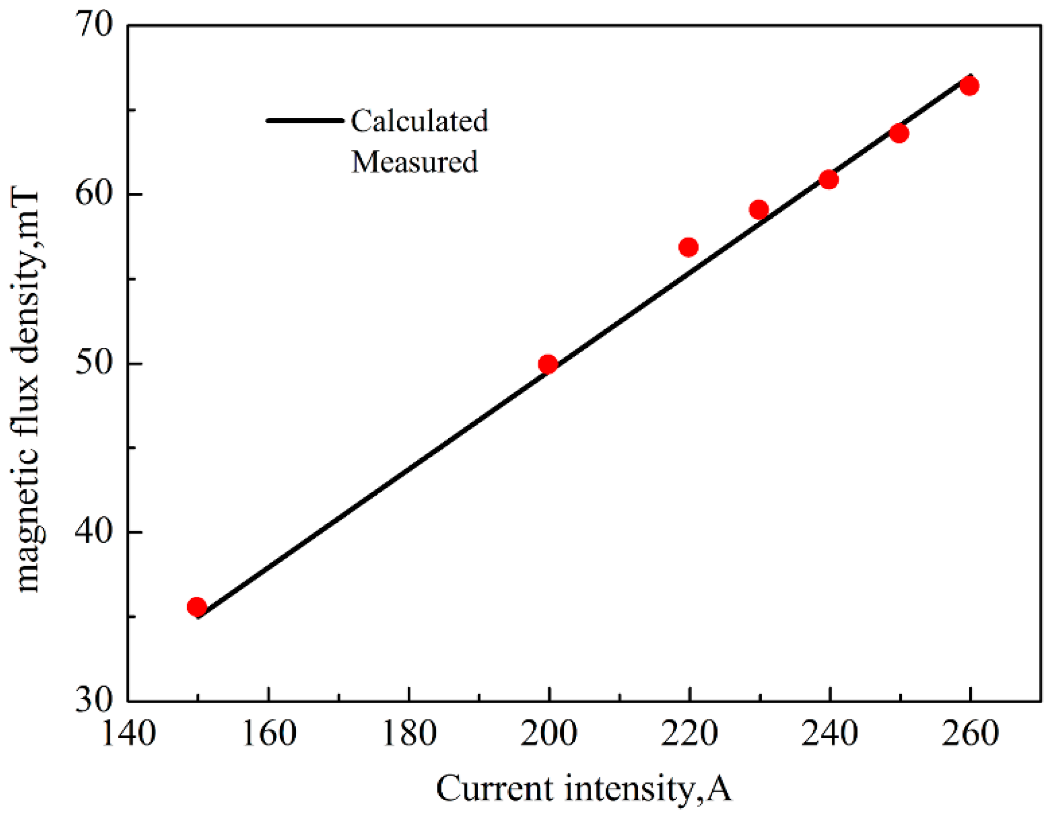
In order to validate the present mathematical model, the magnetic flux density in the center of stirrers with various current intensity is measured with a SHT-III teslameter (HP Spinix Inc., Shenyang, China) when the electromagnetic stirrer runs with no molten steel in the continuous casting mold at current frequency of 4 Hz. A comparison of the calculated magnetic flux density and the measured data is shown in Figure 3. It can be seen that, as the current intensity increases, both the measured value and the calculated measured value have the same trend in that the magnetic flux density increases with the current intensity, and the relative error between the measured value and measured value is small, which indicates that the present model is capable of predicting the electromagnetic field, and can be adopted to investigate the effects of electromagnetic stirring.
4.2. Melt Flow and Solidification
Figure 4 shows the difference of the streamline of fluid flow without M-EMS (I = 0 A) and with M-EMS (I = 200 A 4 Hz). It can be seen that there is only a reflow in the upper part of the mold when I = 0 A when the impinging jet from the SEN flows down into the liquid core and then returns upward along the mold wall, while there are two horizontal swirling flows when I = 200 A, caused by rotating electromagnetic force. Meanwhile, on the plane of Z = 0, it is obvious that there is one upper recirculation zone without M-EMS, but there are two recirculation zones formed on the plane with M-EMS. Due to horizontal swirling effects, the upper recirculation zone is lengthened along the casting direction, and a second recirculation zone is promoted at the mold exit.
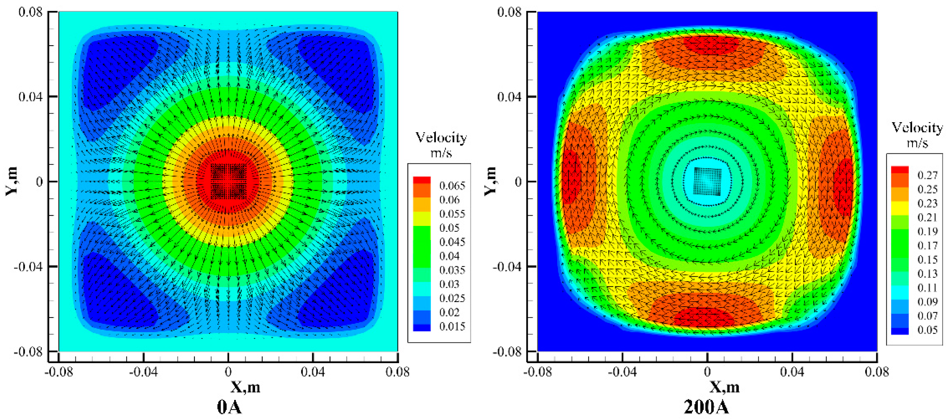
Figure 5 shows the velocity contour and vector on the cross section of the billet at the center of M-EMS, which is located 0.515 m from the meniscus. It can be seen that without M-EMS, the largest fluid flow velocity appears at the center because of the injecting stream from the SEN, and flow velocity gradually decreases from the center to the solidification front at the initial solidified shell. When the M-EMS is on with I = 200 A, the rotational flow on the horizontal plane is promoted under the effects of electromagnetic force induced by interaction of the injecting molten steel stream and the magnetic field, and the largest flow velocity shifts from the center to the solidification front near the billet surface, because the electromagnetic force increases from the center to the billet surface.
Figure 6 shows the velocity contour on the central symmetry plane of strand face (Z = 0), when the M-EMS operates with different current intensities. It is obvious that when the M-EMS is off (I = 0 A), the molten steel stream straightly penetrates deep into the liquid pool of the strand. When the M-EMS is on, the penetration depth of injecting stream from the SEN decreases, and the flow velocity of molten steel in the installation position of M-EMS increases, because of the effects of electromagnetic stirring. Also, the penetration depth of injecting stream becomes shallower and the impact zone of M-EMS becomes larger with the increase in the current intensity. Moreover, the horizontal rotation flow induced by the M-EMS becomes more intense and the flow velocity at the solidification front becomes larger with the increase of current intensity, which means that the wash effects of molten steel on the solidified shell become more significant.
Figure 7 shows the tangential velocity profile along the X direction at the center plane of the stirrer. It can be seen that the tangential velocity increases with the distance away from the center, and reaches the largest value at the solidification front near the billet surface, because the electromagnetic force increases with the distance from the stirrer center. However, due to the wall effects, the flow velocity of molten steel decreases significantly at the solidification front. Meanwhile, with the increase of current intensity, the tangential velocity gradually increases, and the maximum tangential velocities at the solidification front are, respectively, 0.19 m/s, 0.30 m/s, and 0.37 m/s, when the current intensities are respectively 150 A, 200 A, and 240 A.
Figure 8 shows the temperature profile on the plane of Z = 0. It is clear that the high-temperature zone of molten steel shifts upward in the continuous casting mold with M-EMS on, because the electromagnetic stirring inhibits the impingement of injecting stream with high temperature from the SEN, as shown in Figure 6. Also the horizontal swirling flow induced by the electromagnetic stirring makes the temperature of molten steel in the mold more uniform and increases the temperature gradient at the solidification front, which is beneficial for the heat extraction by the water cooling mold. Moreover, with the increase of current intensity, the high-temperature zone of molten steel is gradually restricted to the upper part of continuous casting mold, and more heat of molten steel is extracted by the cooling water in the continuous casting mold, resulting in a lower temperature of molten steel at the mold exit.
Figure 9 shows the growth of shell thickness along the casting direction under the different operations of M-EMS. It is obvious that, due to the high cooling capability of the mold, the molten steel in the mold solidifies quickly and the thickness of the shell increases significantly and evenly when M-EMS is off. However, when the M-EMS is on, the fluid flow in the mold becomes intense and the high-temperature zone moves upwards; thus, the shell growth is inhibited and the shell thickness becomes thin at the M-EMS position. When the current densities are, respectively, 0 A, 150 A, 200 A, and 240 A, the shell thickness at the mold exit are, respectively, 15.7 mm, 11.8 mm, 11.0 mm, and 10.6 mm.
4.3. Distribution of Solute Carbon
Figure 10 shows the carbon concentration field in the continuous casting mold with M-EMS. It can be seen that due to the higher solubility of carbon in the liquid phase than in the liquid phase, the carbon is rejected from the initial solidified shell into the bulk liquid, and thus the carbon concentration at the initial solidified shell is obviously lower than the bulk liquid. Another interesting phenomenon is that a higher carbon concentration zone appears at the mold top near the meniscus, and becomes larger with the increase of current intensity. This phenomenon can be explained by the rejected carbon at the solidification front being washed away and transferred to the mold top by the upward swirling flow, as shown in Figure 4. Moreover, the wash effect of fluid flow induced by electromagnetic stirring on the initial solidified shell becomes more significant with the increase of current intensity and thus the carbon concentration at the initial solidified shell becomes lower and more carbon was transferred to the mold top near the meniscus.
Figure 11 shows the carbon concentration distribution along the centerline of the billet cross section located 1.4 m from the meniscus. It can be seen that the carbon concentration at the billet surface is significantly larger than the nominal concentration, because the upward swirling flow makes the bulk liquid with high carbon concentration gather at the meniscus, as shown in Figure 10, making for a higher carbon concentration in the initial solidified shell. However, the carbon concentration in the initial solidified shell decreases sharply with the distance from the billet surface, and a negative segregation of carbon appears at the billet subsurface. The intensive fluid flow at the solidification front induced by electromagnetic stirring washes the rejected carbon away, which becomes more and more significant with the increase of the current intensity, as shown in Figure 11. Moreover, it should be mentioned here that a billet cross section with 15 mm thickness is collected under the steady casting conditions with M-EMS (I = 240 A, f = 4 Hz). Due to the focus of present study on the initial solidification, the steel scraps are sampled with a ϕ2 mm drill along the centerline from the billet surface to 15 mm. Then, their carbon concentrations are analyzed with a Carbon‒Sulfur analyzer. The measurements is imposed on the carbon concentration field along the centerline of billet cross section, as shown in Figure 11. It can be seen that the calculated carbon concentrations are 0.225%, 0.233%, and 0.254% at X = −0.079 m, 0.078 m, and 0.0795 m, respectively. While, the measured values are 0.214%, 0.225%, and 0.265%, respectively. Therefore, the calculated results agree well with the measurements, and thus verify the success of the present model.
5. Conclusions
In the present study, a multi-physical-field model was developed to predict electromagnetic field, flow field, temperature field, concentration field, and solidification profile during the initial solidification of steel billet in the continuous casting mold with M-EMS. The main conclusions are summarized as follows:
- (1)
- When the M-EMS is on, the horizontal swirling flow appears and make the high-temperature zone shift upward in the continuous casting mold. Also, two swirling flows form on the longitudinal section of continuous casting mold and become more and more intensive with the increase of current intensity.
- (2)
- When the M-EMS is on, the penetration depth of injecting stream from the SEN decreases, and the flow velocity of molten steel at the solidification front increases. Thus, the wash effects of fluid flow on initial solidified shell become intensive and a negative segregation of carbon appears at the billet subsurface, which becomes more significant with the increase of current intensity.
- (3)
- When the M-EMS is on, the swirling flow induced by electromagnetic stirring has a great effect on the initial solidified shell growth and the shell thickness at the mold exit becomes thinner with the increase in current intensity.
Author Contributions
S.L. and M.Z. conceived and designed the study. W.Z. and Y.C. performed the experiments and simulations. W.Z., S.L., and W.W. prepared the original draft.
Funding
This research was funded by the National Key Research and Development Plan (Nos. 2017YFB03044100, 2016YFB0300105-1), the National Natural Science of China (Nos. 51674072, 51704151, 51804067), and the Fundamental Research Funds for the Central Universities (No. N172503013).
Acknowledgments
We are grateful to Shiwei Yin from the School of Metallurgy, Northeastern University, China for his help in testing magnetic induction.
Conflicts of Interest
The authors declare no conflicts of interest.
References
- Thomas, B.G. Review on modeling and simulation of continuous casting. Steel Res. Int. 2018, 89, 1700312. [Google Scholar] [CrossRef]
- Yasuda, H.; Toh, T.; Iwai, K.; Morita, K. Recent progress of EPM in steelmaking, casting, and solidification processsing. ISIJ Int. 2007, 47, 619–626. [Google Scholar] [CrossRef]
- Spitzer, K.H.; Dubke, M.; Schwerdtfeger, K. Rotational electromagnetic stirring in continuous casting of round strands. Metall. Trans. 1986, 17B, 119–131. [Google Scholar] [CrossRef]
- Fujisaki, K.; Ueyama, T.; Okazawa, K. Magnetohydrodynamic calculation of in-mold electromagnetic stirring. IEEE Trans. Magn. 1997, 33, 1642–1645. [Google Scholar] [CrossRef]
- Fujisaki, K.; Satoh, S.; Yamada, T. Consideration of heat transfer and solidification in 3-D MHD calculation. IEEE Trans. Magn. 2000, 36, 1300–1304. [Google Scholar]
- Fujisaki, K.; Wajima, K.; Ohki, T. 3D magnetohydrodynamics analysis method for free surface molten metal. IEEE Trans. Magn. 2000, 36, 1325–1328. [Google Scholar]
- Fujisaki, K.; Yamada, T.; Satoh, S. Magnetohydrodynamic calculation for free surface velocity. J. Appl. Phys. 2001, 89, 6734–6736. [Google Scholar] [CrossRef]
- Natarajan, T.T.; El-Kaddah, N. Finite element analysis of electromagnetically driven flow in sub-mold stirring of steel billets and slabs. ISIJ Int. 1998, 38, 680–689. [Google Scholar] [CrossRef]
- Natarajan, T.T.; El-Kaddah, N. Finite element analysis of electromagnetic and fluid flow phenomena in rotary electromagnetic stirring of steel. Appl. Math. Model. 2004, 28, 47–61. [Google Scholar] [CrossRef]
- Tallbäck, G.R.; Lavers, J.D.; Erraki, A.; Beitelman, L.S. Influence of model parameters on 3-D turbulent flow in an electromagnetic stirring system for continuous billet casting. IEEE Trans. Magn. 2004, 40, 597–600. [Google Scholar] [CrossRef]
- Liu, H.P.; Xu, M.G.; Qiu, S.T.; Zhang, H. Numerical simulation of fluid flow in a round bloom mold with in-mold rotary electromagnetic stirring. Metall. Mater. Trans. B 2012, 43B, 1657–1675. [Google Scholar] [CrossRef]
- Yu, H.Q.; Zhu, M.Y. Influence of electromagnetic stirring on transport phenomena in round billet continuous casting mould and macrostructure of high carbon steel billet. Ironmak. Steelmak. 2012, 39, 574–584. [Google Scholar] [CrossRef]
- Geng, X.; Li, X.; Liu, F.B.; Li, H.B.; Jiang, Z.H. Optimisation of electromagnetic field and flow field in round billet conintuous casting mould with electromagnetic stirring. Ironmak. Steelmak. 2015, 42, 675–682. [Google Scholar] [CrossRef]
- Yang, Z.G.; Wang, B.; Zhang, X.F.; Wang, Y.T.; Dong, H.B.; Liu, Q. Effect of electromagnetic stirring on molten steel flow and soldification in bloom mold. J. Iron Steel Res. Int. 2014, 21, 1095–1103. [Google Scholar] [CrossRef]
- Jiang, D.B.; Zhu, M.Y. Flow and solidification in billet continuous casting machine with dual electromagnetic stirrings of mold and the final solidification. Steel Res. Int. 2015, 86, 993–1003. [Google Scholar] [CrossRef]
- Ren, B.Z.; Chen, D.F.; Wang, H.D.; Long, M.J.; Han, Z.W. Numerical simulation of fluid flow and solidification in bloom continuous casting mould with electromagnetic stirring. Ironmak. Steelmak. 2015, 42, 401–407. [Google Scholar] [CrossRef]
- Ren, B.Z.; Chen, D.F.; Wang, H.D.; Long, M.J. Numerical analysis of coupled turbulent flow and macroscopic solidification in a round bloom continuous casting mold with electromagnetic stirring. Steel Res. Int. 2015, 86, 1104–1114. [Google Scholar] [CrossRef]
- Trindade, L.B.; Nadalon, J.E.A.; Contini, A.C.; Barroso, R.H. Modeling of solidification in continuous casting round billet with mold electromagnetic stirring (M-EMS). Steel Res. Int. 2017, 88, 1600319. [Google Scholar] [CrossRef]
- Dong, Q.P.; Zhang, J.M.; Liu, Q.; Yin, Y.B. Magnetohydrodynamic calculation for electromagnetic stirring coupling fluid flow and solidification in continuously cast billets. Steel Res. Int. 2017, 88, 170067. [Google Scholar] [CrossRef]
- Maurya, A.; Jha, P.K. Influence of electromagnetic stirrer position on fluid flow and solidification in continuous casting mold. Appl. Math. Model. 2017, 48, 736–748. [Google Scholar] [CrossRef]
- Fang, Q.; Ni, H.W.; Zhang, H.; Wang, B.; Lv, Z.A. The effects of a submerged entry nozzle on flow and initial soldification in a continuous casting bloom mold with electromagnetic stirring. Metals 2017, 7, 146. [Google Scholar] [CrossRef]
- Kang, K.G.; Ryou, H.S.; Hur, N.K. Coupled turbulent flow, heat, and solute transport in continuous casitng processes with an electromagnetic brake. Numer. Heat Transf. A 2005, 48, 461–481. [Google Scholar] [CrossRef]
- Lei, H.; Zhang, H.W.; He, J.C. Flow, solidification, and solute transport in a continuous casting mold with electromagnetic brake. Chem. Eng. Technol. 2009, 32, 991–1002. [Google Scholar] [CrossRef]
- Sun, H.B.; Zhang, J.Q. Study on the macrosegregation behavior for the bloom continuous casting: Model development and validation. Metall. Mater. Trans. B 2014, 45B, 1133–1149. [Google Scholar] [CrossRef]
- Fang, Q.; Ni, H.W.; Wang, B.; Zhang, H.; Ye, F. Effects of EMS induced flow on solidification and solute transport in bloom mold. Metals 2017, 7, 72. [Google Scholar] [CrossRef]
- Worster, M.G. Convection in mushy layers. Annu. Rev. Fluid Mech. 1997, 29, 91–122. [Google Scholar] [CrossRef]
- Launder, B.E.; Spalding, D.B. The numerical computation of turbulent flow computer methods. Comput. Methods Appl. Mech. Eng. 1974, 3, 269–289. [Google Scholar] [CrossRef]
- Yang, H.L.; Zhao, L.G.; Zhang, X.Z.; Deng, K.W.; Li, W.C.; Gan, Y. Mathematical simulation on coupled flow, heat, and solute transport in slab continuous casting process. Metall. Mater. Trans. B 1998, 29B, 1345–1356. [Google Scholar] [CrossRef]
- Luo, S.; Zhu, M.Y.; Louhenkilpi, S. Numerical simulation of solidification structure of high carbon steel in continuous casting using cellular automaton method. ISIJ Int. 2012, 52, 823–830. [Google Scholar] [CrossRef]
Figure 1.
Schematic diagram of the calculation domain and boundary condition.

Figure 2.
The flowchart of the 3D mathematical model for predicting the multi-physical phenomena in continuous casting mold with M-EMS.
Figure 2.
The flowchart of the 3D mathematical model for predicting the multi-physical phenomena in continuous casting mold with M-EMS.

Figure 3.
Comparison of the calculated and measured magnetic flux density in M-EMS.

Figure 4.
The streamline of fluid flow in continuous casting mold with M-EMS off (I = 0 A) and on (I = 200 A 4 Hz): (a) 3D, (b) 2D at the plane Z = 0.
Figure 4.
The streamline of fluid flow in continuous casting mold with M-EMS off (I = 0 A) and on (I = 200 A 4 Hz): (a) 3D, (b) 2D at the plane Z = 0.

Figure 5.
The contour and vector of flow field on the cross section at the center of M-EMS: (a) without M-EMS (I = 0 A), (b) with M-EMS (I = 200 A).
Figure 5.
The contour and vector of flow field on the cross section at the center of M-EMS: (a) without M-EMS (I = 0 A), (b) with M-EMS (I = 200 A).

Figure 6.
The velocity contour on the plane of Z = 0.

Figure 7.
Tangential velocity profile along X direction at center plane of the M-EMS.

Figure 8.
The temperature profile on the plane of Z = 0.

Figure 9.
The growth of shell thickness along the casting direction.

Figure 10.
The carbon concentration field in the continuous casting mold with M-EMS.

Figure 11.
Mass fraction of carbon along the X direction 1.4 m below the meniscus.


Table 1.
The chemical compositions of 20CrMnTi steel.
| Element | C | Mn | Si | P | S | Ni | Cr | Cu |
|---|---|---|---|---|---|---|---|---|
| Mass (%) | 0.19 | 0.89 | 0.24 | 0.016 | 0.001 | 0.01 | 1.08 | 0.01 |
Table 2.
The process parameters and physical properties of steel.
| Process Parameter | Physical Parameter of Steel | ||
|---|---|---|---|
| Billet size/mm2 | 160 × 160 | Liquidus temperature/K | 1783 |
| Mold length/mm | 0.8 | Solidus temperature/K | 1757 |
| SEN inner diameter/m | 0.033 | Density/kg·m−3 | 7000 |
| SEN outer diameter/m | 0.09 | Viscosity/kg·m−1·s−1 | 0.0062 |
| SEN submerged depth/m | 0.1 | Thermal conductivity/W·m−1·K−1 | 31 |
| Casting speed/m·min−1 | 1.70 | Specific heat/J·kg−1·K−1 | 650 |
| Pouring temperature/K | 1803 | Latent heat of fusion/J·kg−1 | 250,000 |
| Cooling water Temperature/K | 300 | Thermal expansion coefficient/1·K−1 | 0.0002 |
| Ambient temperature/K | 300 | Solutal expansion coefficient/1 wt %−1 | 0.011 |
| EMS current intensity/A | 150, 200, 240 | Diffusion coefficient of carbon/m2·s−1 | 1 × 10⁻⁸ |
| EMS current frequency/Hz | 4.0 | Equilibrium partition coefficient of carbon | 0.34 |
| - | - | Electric conductivity/S·m−1 | 7.14 × 10⁵ |
| - | - | Magnetic permeability/H·m−1 | 1.257 × 10⁻⁶ |
© 2019 by the authors. Licensee MDPI, Basel, Switzerland. This article is an open access article distributed under the terms and conditions of the Creative Commons Attribution (CC BY) license (http://creativecommons.org/licenses/by/4.0/).
Share and Cite
MDPI and ACS Style
Zhang, W.; Luo, S.; Chen, Y.; Wang, W.; Zhu, M. Numerical Simulation of Fluid Flow, Heat Transfer, Species Transfer, and Solidification in Billet Continuous Casting Mold with M-EMS. Metals 2019, 9, 66. https://doi.org/10.3390/met9010066
AMA Style
Zhang W, Luo S, Chen Y, Wang W, Zhu M. Numerical Simulation of Fluid Flow, Heat Transfer, Species Transfer, and Solidification in Billet Continuous Casting Mold with M-EMS. Metals. 2019; 9(1):66. https://doi.org/10.3390/met9010066
Chicago/Turabian StyleZhang, Wenjie, Sen Luo, Yao Chen, Weiling Wang, and Miaoyong Zhu. 2019. "Numerical Simulation of Fluid Flow, Heat Transfer, Species Transfer, and Solidification in Billet Continuous Casting Mold with M-EMS" Metals 9, no. 1: 66. https://doi.org/10.3390/met9010066
Note that from the first issue of 2016, this journal uses article numbers instead of page numbers. See further details here.