Structure of Solidified Films of CaO-SiO2-Na2O Based Low-Fluorine Mold Flux


1
College of Materials Science and Engineering, Chongqing University, Chongqing 400044, China
2
School of Materials and Metallurgical Engineering, Guizhou Institute of Technology, No.1 Caiguan Road, Guiyang 550003, China
3
Key Laboratory of Light Metal Materials Processing Technology of Guizhou Province, Guizhou Institute of Technology, Guiyang 550003, China
*
Author to whom correspondence should be addressed.
Metals 2019, 9(1), 93; https://doi.org/10.3390/met9010093
Submission received: 4 December 2018
/
Revised: 8 January 2019
/
Accepted: 11 January 2019
/
Published: 16 January 2019
(This article belongs to the Special Issue Ironmaking and Steelmaking)
Abstract
:As an essential synthetic material used in the continuous casting of steels, mold fluxes improve the surface quality of steel slabs. In this study, a CaO-SiO2-Na2O-based low-fluorine mold flux was solidified by an improved water-cooled copper probe with different temperatures of molten flux and different probe immersion times. The heat flux through solid films and the film structures were calculated and inspected, respectively. Internal cracks (formed in the glassy layer of films during solidification) were observed. The formation and evolution of those cracks contributed to the unstable heat flux density. The roughness of the surface in contact with the water-cooled copper probe formed as films were still glassy and the roughness had no causal relationship with crystallization or devitrification. Combeite with columnar and faceted dendritic shapes were the main crystal in the film.
1. Introduction
In the continuous casting of steels, mold fluxes control the heat flux from steel shells to the mold [1,2,3] by forming a solid slag film. For medium-carbon steels, large volume shrinkages caused by peritectic transition (delta ferrite to austenite) at meniscus make some steels quite crack-sensitive [4,5]. Thus, slow and uniform cooling are required to prevent the formation of longitudinal cracks on slab surfaces. The usual method to solve this problem is the use of mold fluxes to lower the heat flux from initial steel shells to the mold near meniscus. Conventional mold fluxes for peritectic steels usually have high fluorine contents and high basicities (binary basicity from 1.2 to 1.5, CaO-SiO2-CaF2-based slags). As an important element in fusion agents (e.g., NaF, CaF2, etc.), fluorine simplifies the microstructure of molten fluxes, decreases its high-temperature viscosities, and promotes the formation of cuspidine (3CaO·2SiO2·CaF2) in solid slag films [6,7,8]. Based on previous approaches [9,10], the precipitation of cuspidine in slag films is widely considered as a major contribution of high-basicity mold fluxes to decrease the heat flux. Therefore, fluorine is considered as a significant component in mold fluxes for peritectic steels, and is usually present in levels up to 10 mass percentage or more. However, fluorine-containing gases (mostly reported as NaF and SiF4) evaporate from molten fluxes at high temperatures. These gases potentially pollute the environment and damage the health of workers. High-fluorine mold fluxes also corrode casters as fluorine dissolves into the second-cooling water to form hydrofluoric acid [11,12].
Based on these disadvantages, efforts towards the development of low-fluorine and fluorine-free mold fluxes have been reported frequently, mostly in CaO-SiO2-Na2O- and CaO-SiO2-TiO2-based systems [13,14,15,16]. However, industrial trials gave unstable performances of these fluorine-free or low-fluorine fluxes for peritectic steels—even their physical properties (i.e., melting temperature, viscosity, break temperature, crystallization capacity, etc.) are similar with conventional high-fluorine ones. Related research gives some possible explanations [17]: TiO2-containing mold fluxes are likely to deteriorate the lubrication capacity of liquid slag films and lead to an unstable casting (sticking or breakouts) because of the formation of titanium carbide and/or titanium carbonitride particles in molten fluxes (TiO2 reacts with the carbon from sintering-control components and dissolved nitrogen in molten fluxes). Besides, the structure and evolution of the fluorine-decreased films during solidification (the roughness of surfaces in contact with the mold, porosity, growth rate, crystallization characteristics, etc.) could be very different from conventional ones with a high-fluorine content, which also affect the performance of mold fluxes directly and are still unclear.
This study selected a typical low-fluorine CaO-SiO2-Na2O-based mold flux (which gives unstable performances in commercial practices) and investigated the structural evolution of its films upon solidification. The structure differences were then compared with conventional high-fluorine ones.
Previous approaches [18] used a water-cooled copper probe to solidify slag films from molten fluxes and obtain heat flux densities. However, some details of the previous probe likely affected the results. First, the intensity cooling of the large probe surpasses the capacity of resistance furnaces to maintain a constant temperature of molten fluxes, resulting in a poor uniformity of film structures (especially the thickness and feature of the surface in contact with the probe). Second, the probe is in a cubic shape with small width–thickness ratio, and the obtained solid films are more likely to be affected by two-dimensional cooling, which could affect the structure of films. To solve those problems, a water-cooled copper probe with a much smaller volume and large width–thickness ratio was developed to obtain consistent film thicknesses, structures, and reliable heat flux densities [19].
2. Experimental Method
2.1. Mold Flux Selection and Slag Film Acquisition
A typical CaO-SiO2-Na2O-based low-fluorine (LF) mold flux was used as the basis of this study (see the composition in Table 1). Compared with conventional high-fluorine fluxes, this mold flux gave unstable performance in the casting of peritectic grade steels. Experimental samples were prepared using analytical-grade reagents (CaCO3, SiO2, Na2CO3, CaF2, and Al2O3).
The physical properties were measured (see Table 2) [20,21,22]. The melting temperature was measured by the hemisphere point method; the high temperature viscosity and viscosity–temperature curve were measured by a high-temperature rotational viscometer (using graphite bobs with 15 mm diameter and graphite crucibles with 55 mm inner diameter). The break temperature was defined as the temperature below which the flux viscosity increases sharply upon cooling at speed 6 K/min. For mold fluxes with a strong crystallization tendency, the break temperature was approximately equal to the liquidus temperature.
For each experiment, 300 g of pre-melted mold flux was loaded into a graphite crucible (60 mm inner diameter) and melted in a resistance furnace. The water-cooled probe was immersed into the melted flux to solidify slag films (probe size: 6 mm in thickness, 20 mm in length, 15 mm in height; immersion depth: 13 mm; cooling water of the probe: 1.75 dm3/ min). The heat flux densities through solid slag films were calculated using Equation (1), where Q is heat flux density, W is flow rate of cooling water, (Tout − Tin) is the temperature increase of water after it passes through the probe, A is the surface area that the probe contacted liquid fluxes, and Cp is the specific heat capacity of water. The solidified films were recovered after different probe immersion times (i.e., 60, 90, and 120 s). Three slag bulk temperatures (1573, 1623, and 1673 K) were used to reveal the effect of bulk temperature on the structure and thermal property of solid films.
2.2. Measurements on Solidified Films
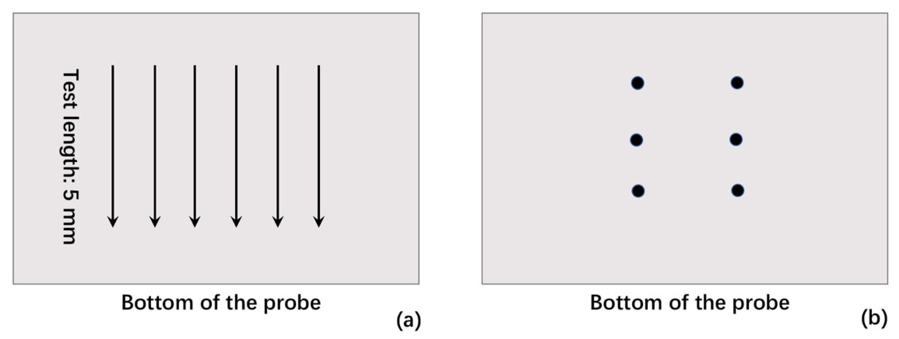
The thickness of solid films was measured with a point micrometer (six measurements for each wide-face film). The roughness of film surfaces in contact with the copper probe was measured with a contact profilometer. The roughness (Ra) measurements were performed on the probe-side surface of each wide-face film (measuring six times). The illustrated positions, length, and direction of the roughness measurements are given in Figure 1a. The illustrated positions of thickness measurements are shown in Figure 1b.
The overall closed porosity of films was calculated. The apparent densities (da) of solid films and true densities (dt, films pulverized into powders with size smaller than 45 μm) were measured by a gas pycnometer. The closed porosity of films can be calculated as (dt − da)/dt.
Surface and internal features of films were inspected with scanning electron and optical microscopies. The cross section samples were prepared after mounting films in resin and polishing with Al2O3 suspension. Samples for SEM were sputter-coated with 2–3 nm of Pt. X-ray diffraction (Cu-Kα radiation) was used to identify the major crystal of the pulverized film (the film sample recovered from molten flux with 1623 K bulk temperature after 120 s immersion of the probe).
3. Results and Discussions
3.1. Thickness and Heat Flux Density of Solid Films
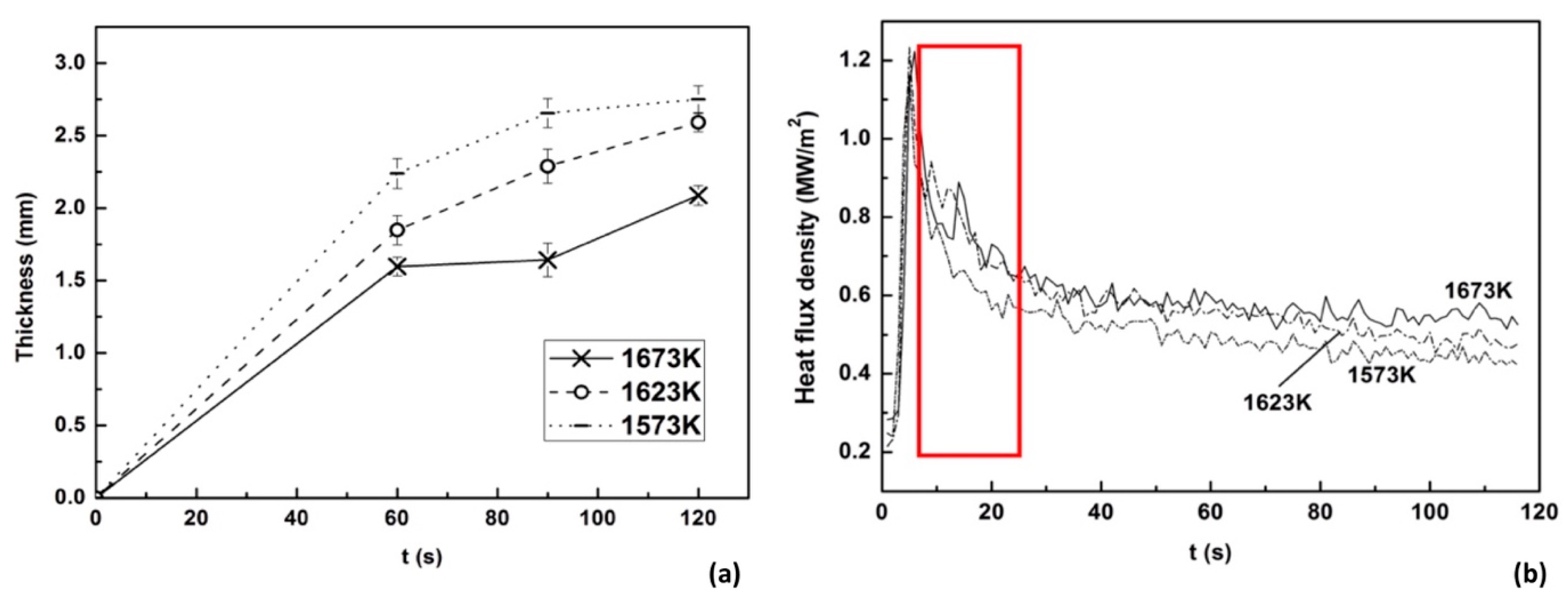
The results of the thickness and heat flux density of films are shown in Figure 2. As expected, the thickness of films increased gradually with decreased slag bulk temperatures and increased probe immersion times. Unstable heat flux densities were detected, especially at higher slag bulk temperature (i.e., 1623 or 1673 K) and short immersion time (within 20 s, as marked with a rectangle in Figure 2). Besides intensive cooling, non-uniform cooling conditions at meniscuses also contributed to the formation of longitudinal cracks on initial steel shells. The unstable heat flux through low-fluorine films may contribute to their unstable performances. Other recent works have shown a similar fluctuation of heat flux through solidified fluorine-free films [19], but for conventional and ultrahigh-basicity mold fluxes (with high F content), no apparent fluctuation was detected [23,24]. The fluctuation of heat flux densities was partially contributed by the formation and evolution of internal cracks of glassy films upon solidification, which is discussed below.
3.2. Cracks Formed in the Glassy Layer
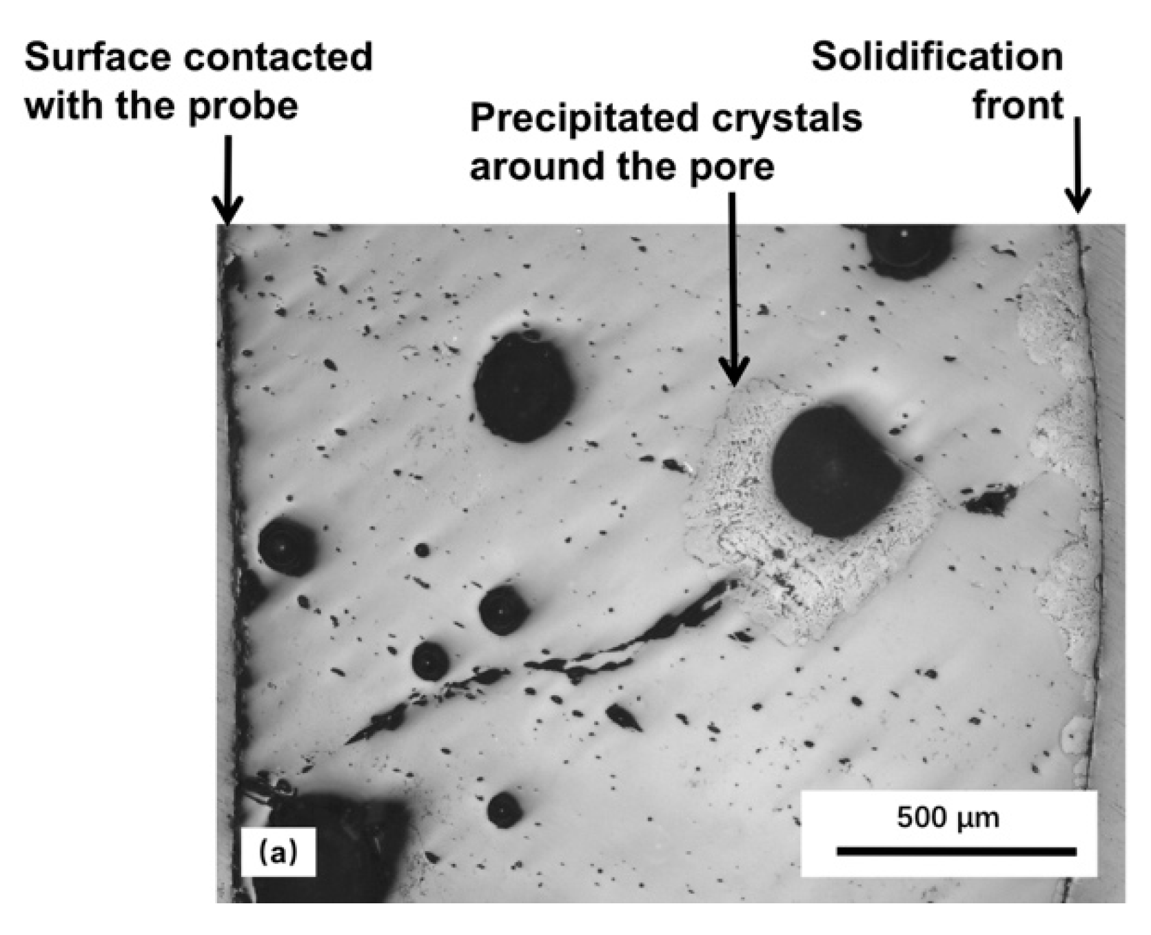
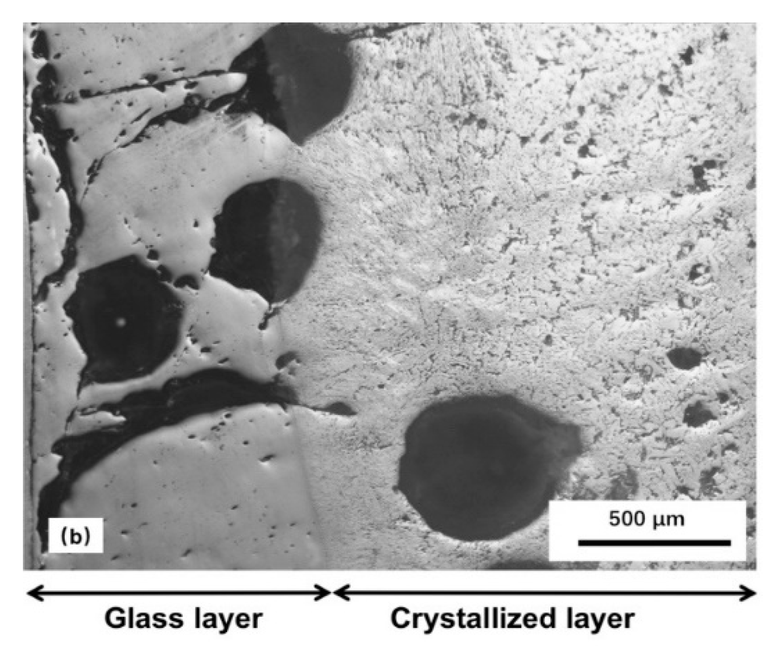
Apparent internal cracks were observed (see Figure 3) in the glassy layer of solid films. The obvious fusion tendency of the crack boundaries indicated that those cracks formed and fused during the immersion of probe in molten fluxes (not formed upon cooling after taking solidified films out of the molten flux). Intensive cooling of the water-cooled copper probe and the large temperature gradients of initial solidified films could cause the formation of cracks. The mechanism of the formation and evolution of those cracks is shown in Figure 4, which indicates that the small pores with irregular shapes in the glass layer (see Figure 3a) are likely formed by the evolution (fusion) of cracks. As the formation of large cracks in the initial glassy film increased its thermal contact resistance (as Figure 4a and 4b show), the fusion of crack boundaries in contrast decreased the thermal contact resistance (Figure 4c). The continual formation and fusion of cracks naturally contributes to the heat flux fluctuation (especially in the early stage of solidification, as shown in Figure 2). No similar cracks and large heat flux fluctuations were observed in solid films with high ratio of crystals [19,23,24].
Several recent studies have suggested that films with higher basicity and cuspidine ratio tend to have a higher conductivity [25,26]. The roughness of film surfaces in contact with the probe has no causal relationship with crystallization [23,24]. Although those approaches indicated that crystals contribute less to heat flux control directly, a low glass-ratio film is still expected to stabilize the heat flux within a micro zone. The worse performance of the low-fluorine mold flux in this work was likely partially caused by unstable heat fluxes through the slag films, because of the formation and fusion of internal cracks in the initial glassy films.
Thus, besides the larger thermal contact resistance provided by the larger surface roughness of solid slag film, which was already proved in other works [23,24], another explanation of the observation that mold fluxes with high basicity and high fluorine content can provide more stable performances than the mold flux applied in this study is that cracks forming in a fully crystallized film do not have the evolution process shown in Figure 4b and 4c. Besides, a thicker film with a smaller ratio of glassy layer also decreases the effect of internal cracks on the heat flux fluctuations.
3.3. Surface Roughness of Solid Films
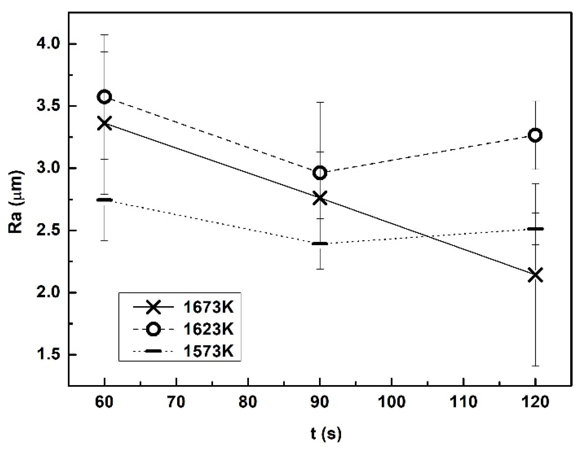
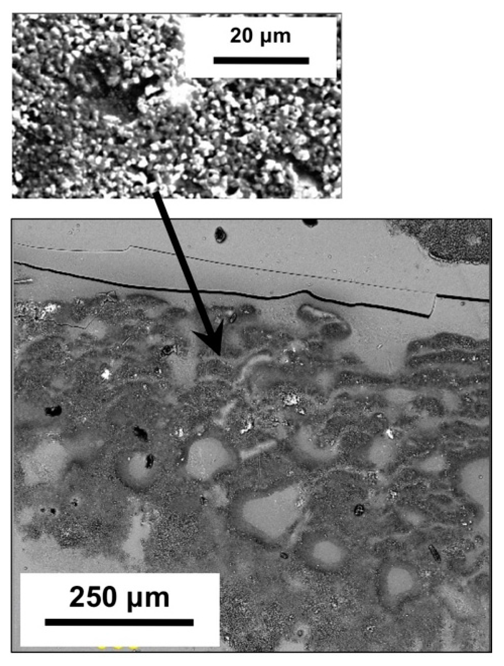
The roughness of film surfaces in contact with the copper wall increases the thermal contact resistance between steel shells and the mold, which is considered as one of the major contributions to heat flux control in continuous casting. The typical feature of film surfaces in contact with the probe is shown in Figure 6 and the measured roughness is given in Figure 5. For films obtained at higher bulk temperatures (i.e., 1623 and 1673 K), the difference of surface roughness was not statistically obvious when the immersion time was less than 90 s. A longer probe immersion time gave lower roughness of films obtained at a slag bulk temperature 1673 K. The lower slag bulk temperature (1573 K) tended to result in lower roughness. Some results demonstrate that the formation of surface roughness for those films was not caused by crystallization or devitrification. The roughness did not increase with increased probe immersion times (even decreased continuously at a slag bulk temperature of 1673 K). Figure 3a shows that the majority of the film cross section was glass, the surface in contact with the probe was amorphous (the small particle with size around several micrometers detailed in Figure 6 is not crystal, which was confirmed by the microscopic analysis), but this film already had a very high roughness (as shown in Figure 5). Compared with the high-basicity and high-fluorine films [23,24], the effect of bulk slag temperatures on roughness fluctuation of low-fluorine films was more obvious in this case.
3.4. Closed Porosity and Crystallization of Films
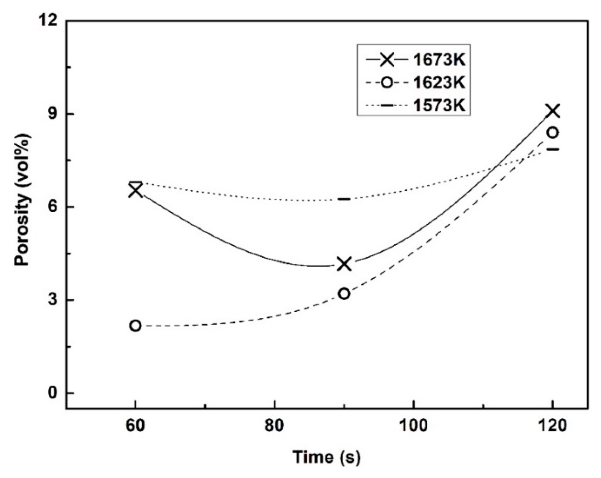
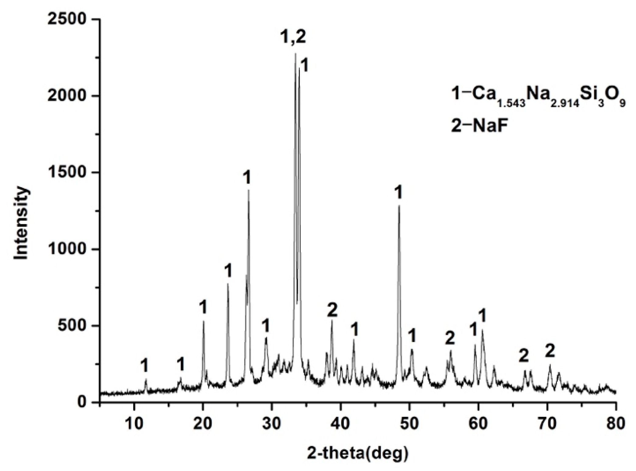
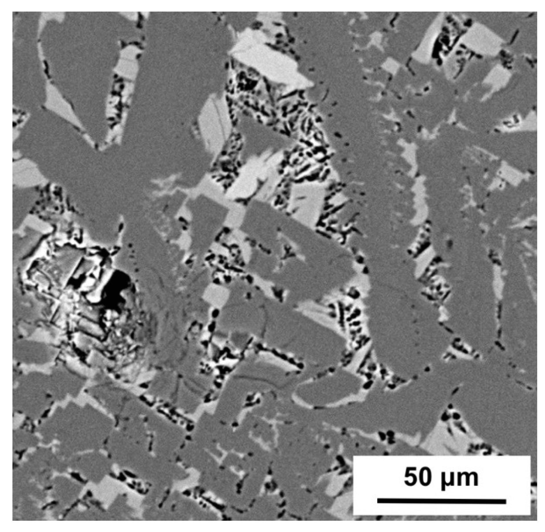
Closed pores in solid slag films decrease the effective thermal conductivity of films. The measured closed porosity of films is shown in Figure 7. The porosity tended to increase upon solidification. This result indicates that pores also formed in the outer layer of solid films, which increased the overall porosity of films (especially for films obtained at 1623 K, their porosity increased from about 2.17 to 8.40 volume percentage from 60 to 120 s immersion of the probe). Regarding the relationship between the formation of pores and crystallization by solidification and devitrification, Figure 3 demonstrates that for this study—similar to high-fluorine mold fluxes [23,24]—before crystallization or devitrification, large pores already existed in the glass films. This indicates that the formation of those large round-shaped pores at the probe side of films had no causal relationship with crystallization or devitrification (although the devitrification may have increased the porosity by forming micro-pores). The X-ray diffraction pattern in Figure 8 shows that the major crystal in the film was combeite (Ca1.543Na2.914Si3O9) and those crystals had columnar and faceted dendritic shapes (similar shape with conventional high-fluorine mold fluxes for peritectic steels, see Figure 9). Compared with conventional mold fluxes, this low-fluorine flux had a much lower crystallization and devitrification rate [23,24].
3.5. Density Evolution of Solidified Films
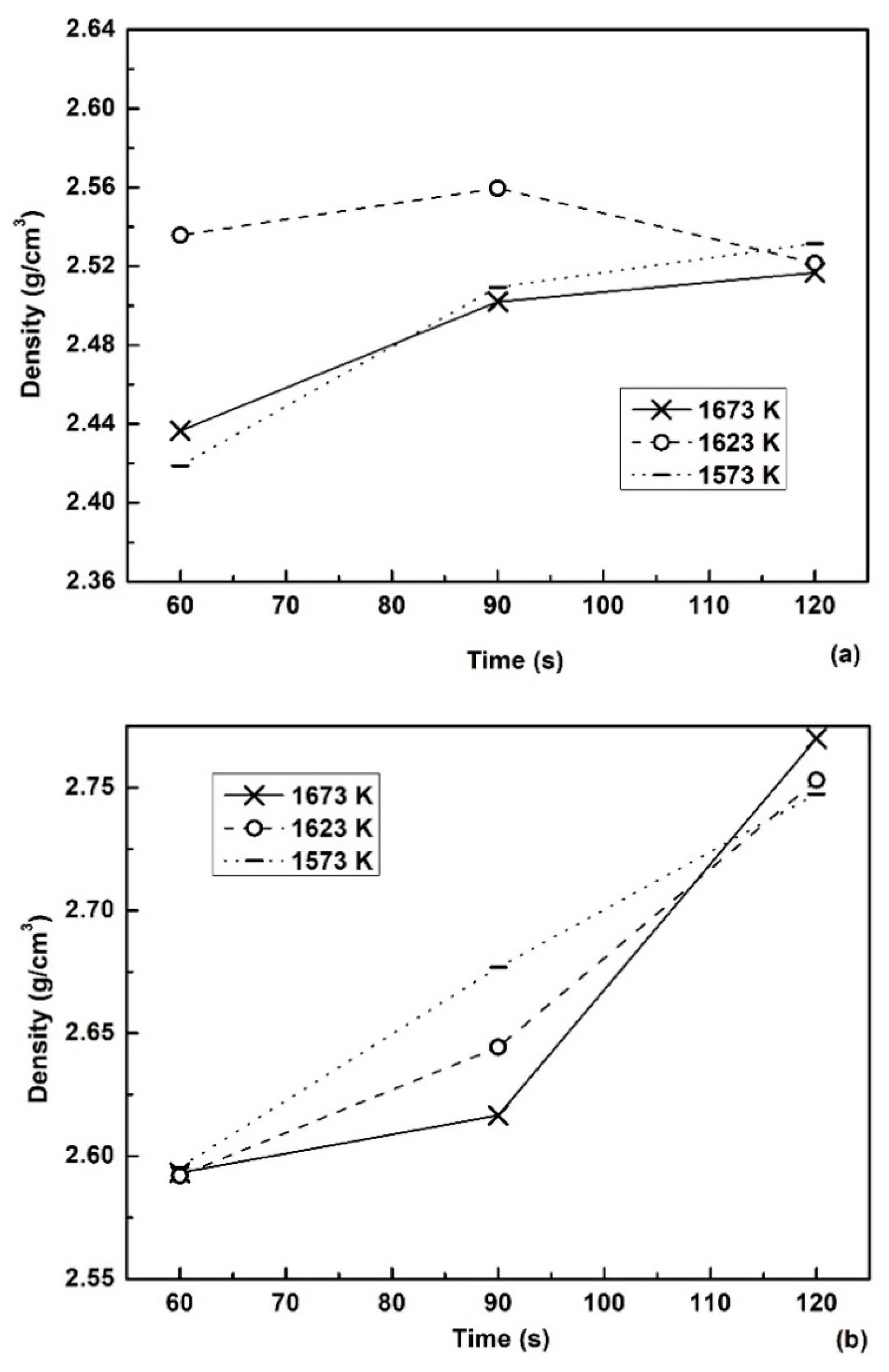
To calculate the closed porosity of films, true densities and apparent densities of slag films in solidification were measured accurately. The density evolution of films was discussed, as it is an important feature of films. The apparent density and true density of films are shown in Figure 10. Results showed that the temperature of liquid slag affected the density of solidified films directly. For the apparent density, films recovered from 1623 K flux gave higher density values than ones recovered from the flux with other temperatures at short probe immersion times (60 and 90 s). This was partially caused by the difference of their closed porosity (see Figure 7). The temperature of molten flux and probe immersion time clearly affected the true density of films. As the initial films were almost glass (as proved by the cross section morphology of films—see Figure 3a), which had a relative low density, films recovered after 60 s of the probe immersion with different bulk temperatures gave similar true densities around 2.59 g/cm3. When the immersion time reached 90 s, higher temperatures of molten fluxes resulted in lower true densities of solidified films. As crystals of mold fluxes tend to have higher densities than the glass matrix, the true density change of solid film directly reflects the crystal ratio of films in solidification. The results indicated that for this mold flux, crystals began to precipitate after 60 s of the probe immersion. For the probe immersion period 60 to 90 s, a higher bulk temperature resulted in a relatively lower crystallization rate and ratio. This was related to the larger temperature gradient of films solidified in high-temperature molten fluxes, because crystallization requires sufficient supercooling at the solidification front. However, in the probe immersion period 90 s to 120 s, the crystallization rate of films solidified in the higher-temperature flux increased obviously. This was caused by a faster devitrification rate in the glassy film at the probe side (i.e., higher bulk temperature gives a larger temperature gradient and also increases the temperature of the probe-side part of films for devitrification).
4. Conclusions
In this study, a low-fluorine mold flux was solidified by an improved water-cooled copper probe. The heat flux through solid films was calculated, and film samples were recovered and inspected. Based on the results, the following conclusions can be drawn:
(1) Internal cracks in initial solidified glassy films were observed. The formation and fusion of those cracks during solidification likely contributed to the fluctuation of heat flux density, especially at the early stage of film solidification.
(2) The roughness of surfaces in contact with the water-cooled probe formed early before crystallization or devitrification, which was obviously affected by the temperature of molten fluxes and probe immersion time. The formation of closed pores in the probe-side glassy films had no causal relationship with crystallization.
(3) Combeite (Ca1.543Na2.914Si3O9) with columnar and faceted dendritic shapes was the major crystal in the solid films.
Author Contributions
conceptualization, X.L. and S.H.; methodology, X.L.; formal analysis, X.L.; investigation, J.Z. and X.L.; resources, X.Y.; data curation, M.L. and Q.W.; writing—original draft preparation, X.L.; writing—review and editing, J.Z.; supervision, S.H.; funding acquisition, S.H.
Funding
This research was funded by Natural Science Foundation of China, grant number 51874057 and U1660204.
Acknowledgments
The authors would like to appreciate the support from Natural Science Foundation of China (project No. 51874057 and U1660204). Professor P. C. Pistorius of Carnegie Mellon University is deeply appreciated for the valuable discussion and guidance on the improved water-cooled copper probe device.
Conflicts of Interest
The authors declare no conflict of interest.
References
- Nakada, H.; Susa, M.; Seko, Y.; Hayashi, M.; Nagata, K. Mechanism of Heat Transfer Reduction by Crystallization of Mold Flux for Continuous Casting. ISIJ Int. 2008, 48, 446–453. [Google Scholar] [CrossRef] [Green Version]
- Yamauchi, A.; Sorimachi, K.; Sakuraya, T.; Fujii, T. Heat Transfer between Mold and Strand through Mold Flux Film in Continuous Casting of Steel. ISIJ Int. 1993, 33, 140–147. [Google Scholar] [CrossRef]
- Mills, K.C.; Fox, A.B. The Role of Mould Fluxes in Continuous Casting-So Simple Yet So Complex. ISIJ Int. 2003, 43, 1479–1486. [Google Scholar] [CrossRef] [Green Version]
- Mills, K.C.; Fox, A.B.; Li, Z.; Thackray, R.P. VII International Conference on Molten Slags, Fluxes & Salts: 25–28 January 2004, Cape Town, South Africa]; The South African Institute of Mining and Metallurgy: Johannesburg, South Africa, 2004. [Google Scholar]
- Brimacombe, J.; Sorimachi, K. Crack formation in the continuous casting of steel. Metall. Trans. B 1977, 8, 489–505. [Google Scholar] [CrossRef]
- Fox, A.; Mills, K.; Lever, D.; Bezerra, C.; Valadares, C.; Unamuno, I.; Laraudogoitia, J.; Gisby, J. Development of Fluoride-Free Fluxes for Billet Casting. ISIJ Int. 2005, 45, 1051–1058. [Google Scholar] [CrossRef] [Green Version]
- Nakada, H.; Fukuyama, H.; Nagata, K. Effect of NaF Addition to Mold Flux on Cuspidine Primary Field. ISIJ Int. 2006, 46, 1660–1667. [Google Scholar] [CrossRef] [Green Version]
- Nakada, H.; Nagata, K. Crystallization of CaO–SiO2–TiO2 slag as a candidate for fluorine free mold flux. ISIJ Int. 2006, 46, 441–449. [Google Scholar] [CrossRef]
- Cho, J.W.; Emi, T.; Shibata, H.; Suzuki, M. Heat transfer across mold flux film in mold during initial solidification in continuous casting of steel. ISIJ Int. 1998, 38, 834–842. [Google Scholar] [CrossRef]
- Seo, M.D.; Shi, C.B.; Cho, J.W.; Kim, S.H. Crystallization behaviors of CaO-SiO2-Al2O3-Na2O-CaF2-(Li2O-B2O3) mold fluxes. Metall. Mater. Trans. B 2014, 45, 1874–1886. [Google Scholar] [CrossRef]
- Persson, M.; Sridhar, S.; Seetharaman, S. Kinetic Studies of Fluoride Evaporation from Slags. ISIJ Int. 2007, 47, 1711–1717. [Google Scholar] [CrossRef] [Green Version]
- Wang, Z.; Shu, Q.; Chou, K. Viscosity of Fluoride-Free Mold Fluxes Containing B2O3 and TiO2. Steel Res. Int. 2013, 84, 766–776. [Google Scholar] [CrossRef]
- Fan, G.; He, S.; Wu, T.; Wang, Q. Effect of Fluorine on the Structure of High Al2O3-Bearing System by Molecular Dynamics Simulation. Metall. Mater. Trans. B 2015, 46, 2005–2013. [Google Scholar] [CrossRef]
- Lu, B.; Wang, W. Effects of Fluorine and BaO on the Crystallization Behavior of Lime–Alumina-Based Mold Flux for Casting High-Al Steels. Metall. Mater. Trans. B 2015, 46, 852–862. [Google Scholar] [CrossRef]
- He, S.; Wang, Q.; Xie, D.; Xu, C.; Li, Z.S.; Mills, K.C. Solidification and crystallization properties of CaO-SiO2-Na2O based mold fluxes. Int. J. Min. Metall. Mater. 2009, 16, 261–264. [Google Scholar] [CrossRef]
- Wen, G.; Sridhar, S.; Tang, P.; Qi, X.; Liu, Y. Development of fluoride-free mold powders for peritectic steel slab casting. ISIJ Int. 2007, 47, 1117–1125. [Google Scholar] [CrossRef]
- Wang, Q.; Lu, Y.; He, S.; Mills, K.; Li, Z.S. Formation of TiN and Ti (C, N) in TiO2 containing, fluoride free, mould fluxes at high temperature. Ironmak. Steelmak. 2011, 38, 297–301. [Google Scholar] [CrossRef]
- Ryu, H.; Zhang, Z.; Wen, J.W.C.G.; Sridhar, S. Crystallization behaviors of slags through a heat flux simulator. ISIJ Int. 2010, 50, 1142–1150. [Google Scholar] [CrossRef]
- Lara Santos Assis, K. Heat Transfer through Mold Fluxes: A New Approach to Measure Thermal Properties of Slags. Ph.D. Thesis, Carnegie Mellon University, Pittsburgh, PA, USA, February 2016. [Google Scholar]
- Long, X.; He, S.; Xu, J.; Huo, X.; Wang, Q. Properties of high basicity mold fluxes for peritectic steel slab casting. J. Iron Steel Res. Int. 2012, 19, 39–45. [Google Scholar] [CrossRef]
- He, S.; Long, X.; Xu, J.; Wu, T.; Wang, Q. Effects of crystallisation behaviour of mould fluxes on properties of liquid slag film. Ironmak. Steelmak. 2012, 39, 593–598. [Google Scholar] [CrossRef]
- Wu, T.; Wang, Q.; He, S.; Xu, J.; Long, X.; Lu, Y. Study on properties of alumina-based mould fluxes for high-Al steel slab casting. Steel Res. Int. 2012, 83, 1194–1202. [Google Scholar] [CrossRef]
- Long, X.; Wang, Q.; He, S.; Pistorius, P.C. Structure evolution of slag films of ultrahigh-basicity mold flux during solidification. Metall. Mater. Trans. B 2017, 48, 1938–1942. [Google Scholar] [CrossRef]
- Long, X.; He, S.; Wang, Q.; Pistorius, P.C. Structure of solidified films of mold flux for peritectic steel. Metall. Mater. Trans. B 2017, 48, 1652–1658. [Google Scholar] [CrossRef]
- Kromhout, J.A.; Dekker, E.R.; Kawamoto, M.; Boom, R. Challenge to control mould heat transfer during thin slab casting. Ironmak. Steelmak. 2013, 40, 206–215. [Google Scholar] [CrossRef]
- Andersson, S.P.; Eggertson, C. Thermal conductivity of powders used in continuous casting of steel, part 1—Glassy and crystalline slags. Ironmak. Steelmak. 2015, 42, 456–464. [Google Scholar] [CrossRef]
Figure 1.
(a) Illustrated positions of surface roughness measurements and (b) thickness measurements. Films for measurement were recovered from the wide face of the probe.
Figure 1.
(a) Illustrated positions of surface roughness measurements and (b) thickness measurements. Films for measurement were recovered from the wide face of the probe.

Figure 2.
(a) Thickness of solid films after different immersion times in molten fluxes with different bulk temperatures (error bars show standard deviations); and (b) Measured heat flux density.
Figure 2.
(a) Thickness of solid films after different immersion times in molten fluxes with different bulk temperatures (error bars show standard deviations); and (b) Measured heat flux density.

Figure 3.
Cross sections of films recovered from the molten flux with 1623 K bulk temperature, after (a) 60 s and (b) 90 s of probe immersion. The left side of micrographs is the probe side; crystals started to precipitate around the edge of pores in (a). (Optical micrographs; black regions and spots are pores and cracks).


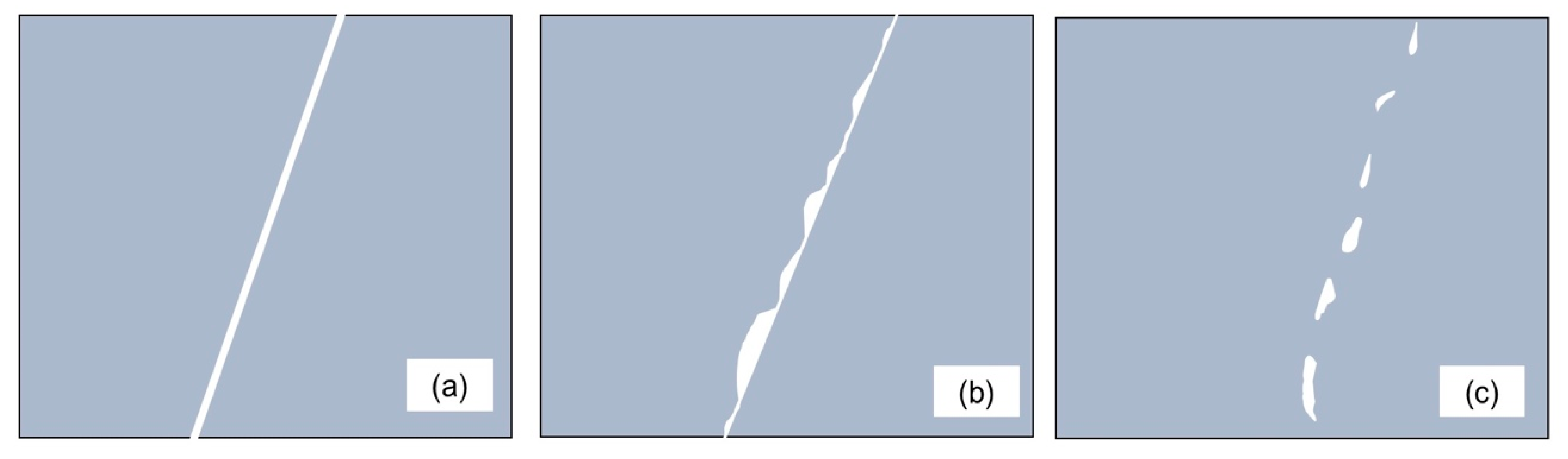
Figure 4.
Schematic of the formation and evolution of cracks in the glassy layer (left side of each graph refers to the probe side): (a) formation of initial cracks; (b) the probe-side surface of the crack had a lower temperature (contributed by the interfacial thermal resistance of the crack) and larger shrinkage ratio upon cooling; (c)some parts of the crack interface melted (molten flux side), and isolated pores with irregular shapes formed (the white areas in (c) are pores).

Figure 5.
Roughness of film surfaces in contact with the water-cooled copper probe, for films formed in molten flux with different bulk temperatures after different probe immersion times. Error bars give the standard deviations.
Figure 5.
Roughness of film surfaces in contact with the water-cooled copper probe, for films formed in molten flux with different bulk temperatures after different probe immersion times. Error bars give the standard deviations.

Figure 6.
Appearance of the surface of a slag film in contact with the probe. Film recovered after 60 s of immersion of the probe in 1623 K mold flux (the film was almost glassy; secondary electron image).
Figure 6.
Appearance of the surface of a slag film in contact with the probe. Film recovered after 60 s of immersion of the probe in 1623 K mold flux (the film was almost glassy; secondary electron image).

Figure 7.
Closed porosity of films obtained at different slag bulk temperatures and probe immersion times.
Figure 7.
Closed porosity of films obtained at different slag bulk temperatures and probe immersion times.

Figure 8.
X-ray diffraction pattern of pulverized solid film (probe immersion time: 120 s; slag temperature: 1623 K; Cu-Kα radiation).
Figure 8.
X-ray diffraction pattern of pulverized solid film (probe immersion time: 120 s; slag temperature: 1623 K; Cu-Kα radiation).

Figure 9.
Typical backscattered electron micrograph of crystals in the solid film. The film was recovered after immersing the probe for 120 s in molten flux with a bulk slag temperature of 1623 K.
Figure 9.
Typical backscattered electron micrograph of crystals in the solid film. The film was recovered after immersing the probe for 120 s in molten flux with a bulk slag temperature of 1623 K.

Figure 10.
(a) Apparent densities and (b) true densities of slag films obtained at different slag bulk temperatures and probe immersion times.
Figure 10.
(a) Apparent densities and (b) true densities of slag films obtained at different slag bulk temperatures and probe immersion times.


Table 1.
Composition of mold flux and mass percentages.
| CaO%/SiO2% | Al2O3 | Na2O | F |
|---|---|---|---|
| 0.7 | 1 | 23 | 3 |
Table 2.
Physical property of the mold flux.
| Viscosity1300°C, Pa·s | Melting Temperature, K | Break Temperature, K |
|---|---|---|
| 0.183 | 1431 | 1480 |
© 2019 by the authors. Licensee MDPI, Basel, Switzerland. This article is an open access article distributed under the terms and conditions of the Creative Commons Attribution (CC BY) license (http://creativecommons.org/licenses/by/4.0/).
Share and Cite
MDPI and ACS Style
Zeng, J.; Long, X.; You, X.; Li, M.; Wang, Q.; He, S. Structure of Solidified Films of CaO-SiO2-Na2O Based Low-Fluorine Mold Flux. Metals 2019, 9, 93. https://doi.org/10.3390/met9010093
AMA Style
Zeng J, Long X, You X, Li M, Wang Q, He S. Structure of Solidified Films of CaO-SiO2-Na2O Based Low-Fluorine Mold Flux. Metals. 2019; 9(1):93. https://doi.org/10.3390/met9010093
Chicago/Turabian StyleZeng, Jianhua, Xiao Long, Xinchen You, Min Li, Qiangqiang Wang, and Shengping He. 2019. "Structure of Solidified Films of CaO-SiO2-Na2O Based Low-Fluorine Mold Flux" Metals 9, no. 1: 93. https://doi.org/10.3390/met9010093
Note that from the first issue of 2016, this journal uses article numbers instead of page numbers. See further details here.