Research on the Friction Stir Welding of Sc-Modified AA2519 Extrusion


Faculty of Mechanical Engineering, Military University of Technology, 2 gen. S. Kaliskiego str., 00-908 Warsaw, Poland
*
Author to whom correspondence should be addressed.
Metals 2019, 9(10), 1024; https://doi.org/10.3390/met9101024
Submission received: 23 August 2019
/
Revised: 17 September 2019
/
Accepted: 19 September 2019
/
Published: 21 September 2019
(This article belongs to the Special Issue Friction Stir Welding Prospective on Light-Alloys Joints)
Abstract
:The aim of this research was to investigate the effect of friction stir welding (FSW) parameters on microstructure and mechanical properties of Sc-modified AA2519 extrusion joints. The workpiece was welded by FSW in non-heat-treated condition with seven different sets of welding parameters. For each obtained joint macrostructure and microstructure observations were performed. Mechanical properties of joints were investigated using tensile test together with localization of fracture location. Joint efficiencies were established by comparing measured joints tensile strength to the value for base material. The obtained results show that investigated FSW joints of Sc-modified AA2519 in the non-heat-treated condition have joint efficiency within the range 87–95%. In the joints obtained with the lowest ratio of the tool rotation speed to the tool traverse speed, the occurrence of imperfections (voids) localized in the stir zone was reported. Three selected samples were subjected to further investigations consisting microhardness distribution and scanning electron microscopy fractography analysis. As the result of dynamic recrystallization, the microhardness of the base material value of 86 HV0.1 increased to about 110–125 HV0.1 in the stir zone depending on the used welding parameters. Due to lack of the strengthening phase and low strain hardening of used alloy the lack of a significantly softened zone was reported by both microhardness analysis and investigation of the fractured samples.
1. Introduction
Friction stir welding (FSW) is a solid-state welding process invented by The Welding Institute (TWI), which provides many advantages compared to conventional welding processes [1,2,3]. Using FSW it is possible to obtain high-quality joints of aluminum alloys, what makes this technology very attractive for the automotive, aerospace, and shipbuilding industry [2,4,5]. Recent research indicates that this technology also provides wide possibilities in the manufacturing of light-alloy based metal-ceramic composites, welding of dissimilar alloys, and modification of surface [6,7,8,9,10]. The main idea of the FSW process is affecting a workpiece with a rotating tool consisting of pin and shoulder [1,2,3,11]. The friction between the workpiece and the shoulder of the tool generates heat which causes the plasticization of material and at the same time, the pin forms the joint by mixing the plasticized material of the workpiece [2,11]. This welding technique has many advantages compared to traditional welding technologies in terms of joining aluminum and its alloys. Since an aluminum alloy does not undergoes melting during joining there is no problem of porosity and no shielding gases are needed [3]. Additionally, considering a solidification of high-strength aluminum-copper alloys in the traditional welding process the very important matter is the difference in the solidification temperature of aluminum (660 °C) and Al/Al2Cu eutectic (548 °C), what causes a high risk of hot cracking [12,13,14,15,16]. In the case of friction stir welding, this problem does not occur because the temperature of the process is lower than Al/Al2Cu eutectic temperature [2,17,18,19]. For this reason, FSW has a great potential in terms of joining high-strength aluminum alloys having high copper concentration, such as AA2219 and AA2519 [10,18,20,21,22]. AA2519 is an alloy with great interests, particularly in military applications due to its high specific strength and good ballistic performance [10,23,24]. This alloy also is a component of some of light-alloy laminated composite plates with excellent ballistic resistance [25,26]. The modification of AA2519 alloy used in this research consists of the addition of scandium and has been developed by the Institute of Non-Ferrous Metals, Light Metals Division in Skawina (Poland). Al3Sc precipitates improve properties of aluminum alloy in many ways including an increase of mechanical properties and recrystallization temperature as well as grain refinement [27,28,29,30]. Previous research performed by authors of this paper reveals that Al3 (Sc,Zr) precipitates do not dissolve due to the FSW process and form dispersion of fine precipitate in the stir zone [10]. Additionally, the increase of recrystallization temperature allows to limit the grain growth in the heat-affected zone during welding process.
In this work authors aim to investigate the effect of the friction stir welding process on mechanical properties and microstructure of Sc-modified AA2519 extrusion. AA2519 used in this investigation is non-heat-treated condition, so it consists of soft aluminum matrix and hard Al2Cu precipitates. Such system subjected to the friction stir welding results in the dissolution of Al2Cu precipitates in the stir zone forming the supersaturated solution [10]. In contrast to an alloy subjected to the precipitation hardening process, the microhardness of non-heat-treated alloy increases in the stir zone due to grain refinement and in the microstructure, there is no strengthening phase (e.g., θ’) to dissolve, coarse or overage [31,32,33]. Furthermore, in this investigation the alloy in the form of extrusion is used, in which the effect of material work hardening is minimal. The material in this condition is easy to form and to weld by FSW. This solution allows to weld AA2519 with the possibility of further forming of the obtained joint before the final heat treatment of precipitation hardening. Literature consists of research concerned with forming of FSW joints including stamping, rolling, or equal channel angular pressing (ECAP) [4,34,35,36,37]. However, before that, it is important to establish appropriate parameters of the welding process and to investigate the properties of the joint. The relationship between welding parameters and joint properties was the subject of many studies involving both experimental and simulation methods a.i. Artificial Neural Network [2,22,38,39,40]. Properties such as microhardness and ultimate tensile strength of the joint strongly depend on parameters of the process which finds their reflection in the amount of heat affecting the welded material [41]. The joint properties are mainly determined by heat input of the process being a function of i.a. tool rotation speed and tool traverse speed [38,42]. Although the most commonly aluminum alloys used in industry were widely examined in terms of the parameters-properties relationship, publications on the Sc-containing aluminum alloys are still a significant research gap [1,2,5,10,33,38,40]. In the case of AA2519 alloy, only a few investigations are concerned with the influence of friction stir welding on the properties of the joint [10,20,43].
This paper focuses on the examination of AA2519 FSW joints in terms of the relationship between welding parameters (tool rotation speed and tool traverse speed) and properties of the joints. The investigation involves examination of the mechanical properties and microstructure of welded material using light and scanning electron microscopy observations, tensile test, microhardness analysis, and fracture surface analysis, in which the results allow to identify the imperfections in the weld, determinate joint efficiency, and as a consequence to establish the optimal parameters of the process.
2. Materials and Methods
The workpiece to be joined was 5 mm thick Sc-modified AA2519 extrusions with dimensions of 80 × 250 mm. The alloy was used in as-extruded non-heat-treated condition. Chemical composition and mechanical properties of as-extruded Sc-modified AA2519 are presented in Table 1 and Table 2, respectively. It is worth noticing that this specific version of AA2519 developed by the Institute of Non-Ferrous Metals, Light Metals Division in Skawina has high concentration of both scandium and zirconium.
The friction stir welding process was performed by using ESAB FSW Legio 4UT machine (ESAB, Warsaw, Poland) with an axial force equal to 17 kN and the tilt angle of MX Triflute tool set to 2° for seven different sets of welding parameters. The dimensions of the tool and the used welding parameters are given in Table 3 and Table 4 respectively. Due to constant axial force (17 kN) the heat input ratio can be expressed as the following equation (Equation (1)):
where Q is the total heat input (J/mm), ω (rpm) is the tool rotation speed and v (mm/min) is tool traverse speed [42]. Welding parameters were chosen according to previous own research results [10]. The main assumption of proposed parameters was to maximize the tool traverse speed (what is a desirable factor in the industry use) without lowering the heat input ratio below 1 to avoid insufficient plasticization of the workpiece.
Basic mechanical properties of the joints were examined by tensile testing according to ASTM standard E8/E8M–13a [44]. The scheme of sample is presented in Figure 1. Tensile tests were carried out on INSTRON 8802 MTL universal testing machine (INSTRON, Warsaw, Poland) with WaveMatrix computer software. The strain extensometer (2620-604, INSTRON, Warsaw, Poland) with a gauge length of 50 mm was used to measure deformation. During the test, the values of load, position, and strain were recorded. For each sample, three tensile tests were performed. The average values of tensile strength and elongation together with their standard deviations were established. The joint efficiency was calculated as a percentage ratio of joint tensile strength to base material tensile strength.
The welded joints were sectioned perpendicular to the welding direction where metallurgical examinations and hardness measurements were carried out. In order to investigate the macrostructure of the joints, samples were examined using a digital light microscope (Olympus LEXT OLS 4100, OLYMPUS, Warsaw, Poland) and scanning electron microscope (Jeol JSM-6610, JEOL., Warsaw, Poland). As the part of metallographic sample preparation, samples were cut along the axial direction using a precision diamond saw and then mounted in resin, grinded with abrasive paper of 80, 320, 600, 1200, and 2400 gradations, and polished using diamond pastes (3 and 1 μm gradation). The samples were etched by using Kroll reagent (20 mL H2O + 5 mL HNO3 + three drops of HF) with etching time equal to 15 s. The Vickers microhardness of selected welds were measured on the cross-section of polished samples by applying load of 0.98 N. The distribution of microhardness was performed for the upper, middle, and lower part of the cross-section: 0.6, 2.5, and 3.9 mm from the top, respectively.
3. Results and Discussion
The light microscopy images of macrostructure of the obtained AA2519 FSW joints are presented in Figure 2. In all analyzed samples the advancing and retreating side are localized on the left and the right side of the cross-section, respectively.
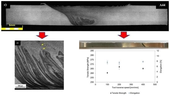
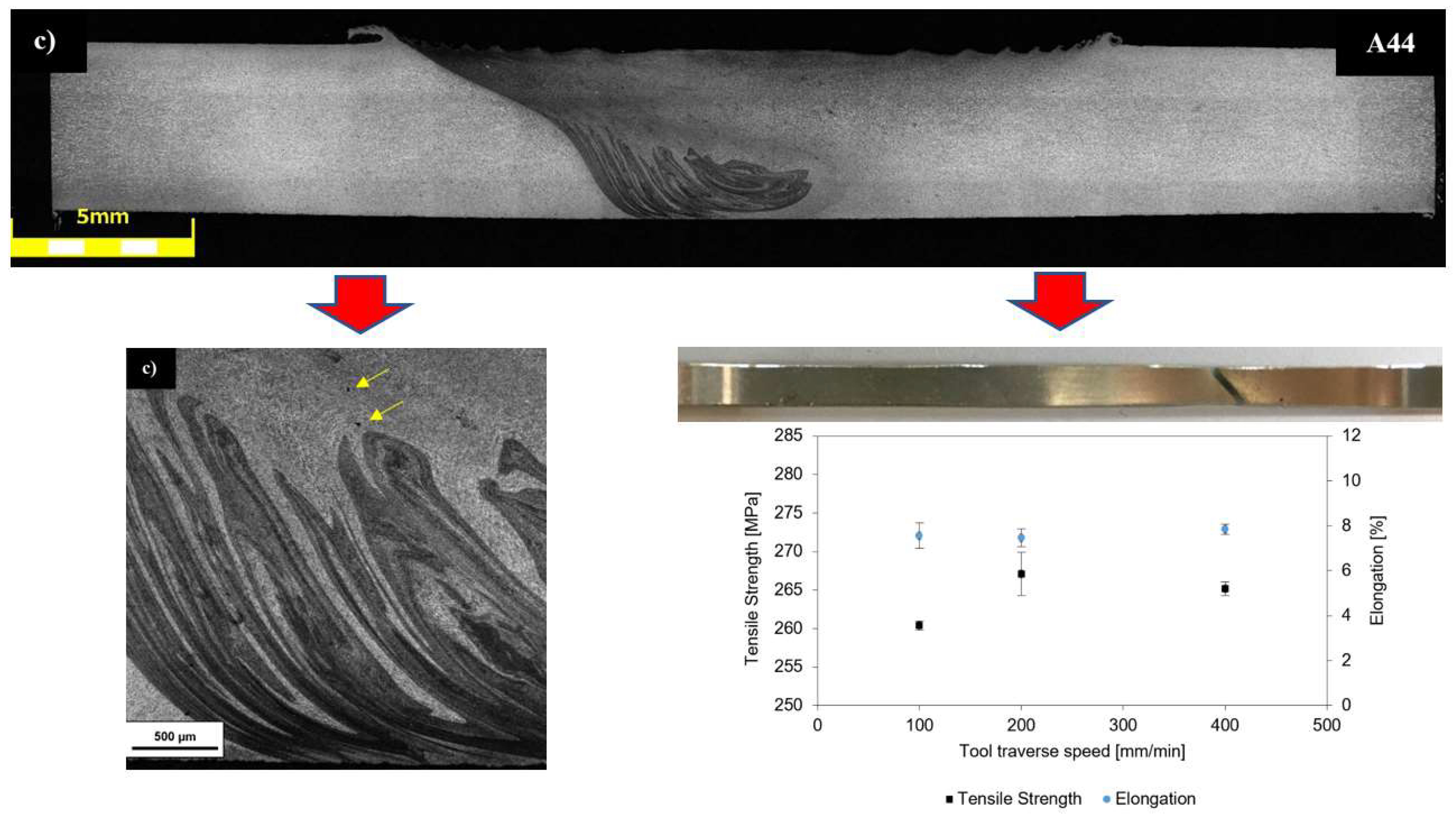
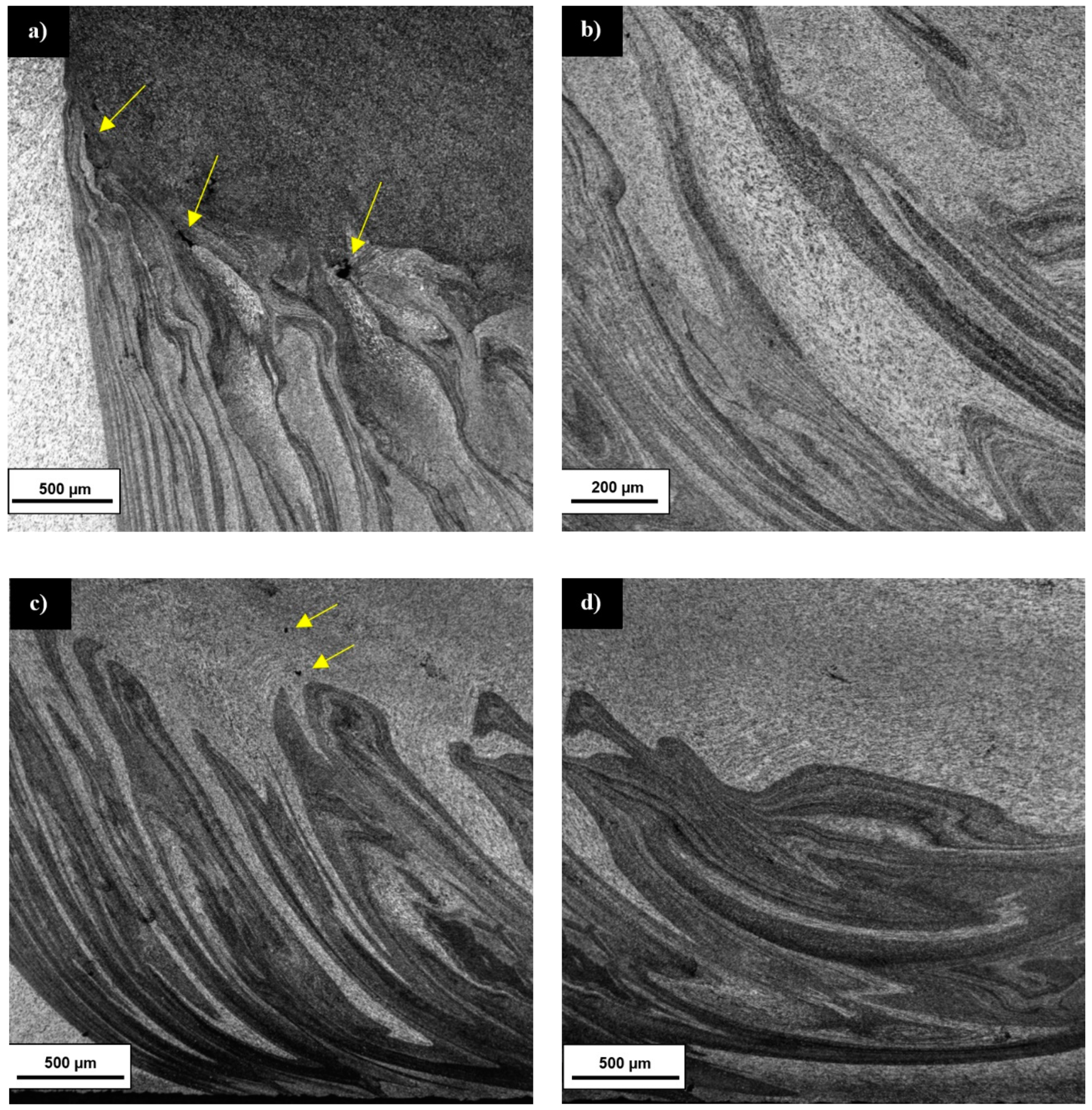
Macroscopic observations of the joints do not show any visible imperfections in the form of cracks or large voids. It can be observed that the tool rotation speed determines the shape of stir zone. In the case of joints obtained by the 400 rpm tool rotation speed, their stir zones exhibit an oblique shape with an angle about 45° on the advancing side. For 800 rpm joints, the rounded shape of this area is reported. Microscopic observations of the joints allow to identify imperfections in A88 and A44 samples localized in the upper part of stir zone next to the advancing side (Figure 3a,c respectively). These imperfections have the form of voids and are present on the top of contrasting bands (so-called “onion rings”). The voids have a larger size in the A88 sample. The visible inhomogeneities of the stir zones in samples A42, A44, and A88 may be partly an effect of Al2Cu dissolution in this area. Therefore, the supersaturated solution is more affected by Kroll reagent than the equilibrium solution because of higher chemical potential. At the same time, these samples have the lowest ratio of the rotation speed to the traverse speed what results in low heat input compared to the other samples and can lead to the insufficient plasticization of the welded material. This phenomenon can be mostly observed in the A88 sample, where bands are very irregular and some areas have a visible deformation texture what is indicated on the incomplete process of the dynamic recrystallization (Figure 3b). The presence of the similar areas is noticed in the A44 sample (Figure 3d).
These observations allow to draw a conclusion that samples A44 and A88 suffered insufficient plasticization during the friction stir welding process. The most visible consequence of this phenomenon is the presence voids in the stir zone close to the advancing side, which receives a lower heat input compared to the retreating side [45,46]. At the same time, the samples obtained with a higher ratio of the tool rotation speed to the tool traverse speed are free of voids and are characterized by ultrafine, equiaxial grain microstructure formed by dynamic recrystallization process (Figure 4a,b). It can be observed that even for samples with the different heat input as A42 (Figure 4a) and A81 (Figure 4b) the grain refinement is on a similar level and no presence of deformed non-recrystallized areas is reported.
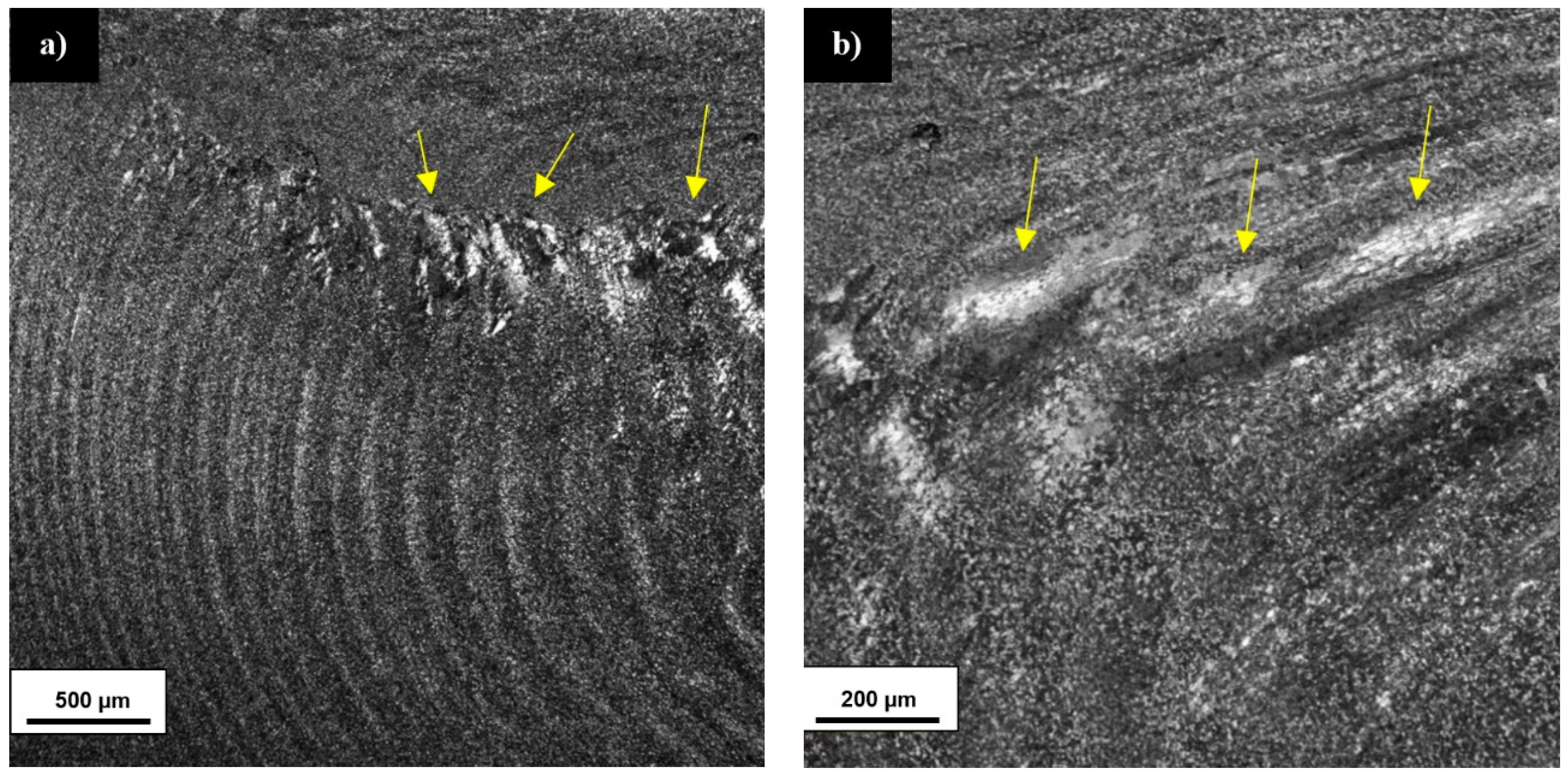
In the stir zone of samples A41, A81, and A82 it is possible to observe characteristic areas distinctive from the rest of stir zone microstructure (Figure 5a). These areas occur mostly in the upper parts of onion rings on the weld advanced side with a tendency to increase their size together with approaching the stir zone center (Figure 5a). They reach their largest size in the center part of the stir zone (Figure 5b).
Although, the reported areas on the macroscopic level look like large-grain structures (Figure 2d), the microscopic observations reveal their sub-grain microstructure (Figure 5b). The presence of such structures in the stir zone can be an effect of the geometric dynamic recrystallization [47]. This process takes place during flattening of the original grains to the diameter of the subgrain size without the phenomenon of subgrain rotation recrystallization [48]. At high temperatures and low strain rate this process can occur, but the presence of grain growth inhibiting precipitates in the microstructure shifts its kinetic towards a higher strain rate [47,49]. As was mentioned in the previous part, the investigated alloy contains a high concentration of zirconium (0.19%) and scandium (0.16%), which form Al3 (Sc,Zr) precipitates pinning subgrain boundaries [50]. Previous research performed by authors of this paper confirmed that Al3 (Sc,Zr) precipitates do not dissolve in the stir zone and form dispersion of particles with the diameter about 1 μm [10]. The influence of Al3 (Sc,Zr) particles on the process of geometric dynamic recrystallization can explain the fact that subgrain structures were found in the samples A41, A81, and A82, having the highest ratio of the tool rotation speed to the tool traverse speed resulting also in the highest heat input.
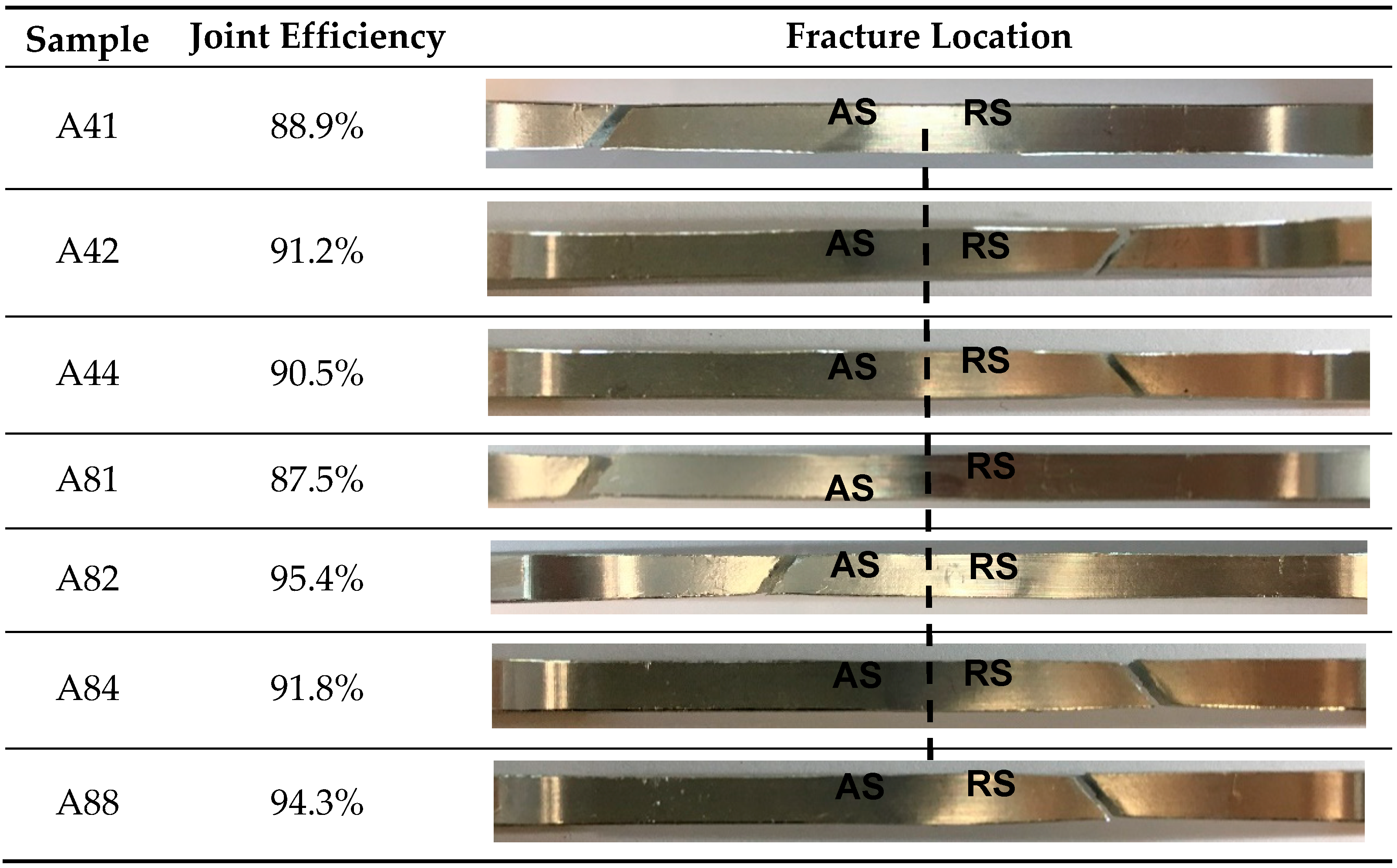
The obtained tensile curves together with the established tensile strength and elongation for samples obtained with 400 and 800 rpm tool rotation speeds are presented in Figure 6, Figure 7, Figure 8 and Figure 9. The estimated values of joint efficiency together with fracture location in the representative samples are provided in Table 5.
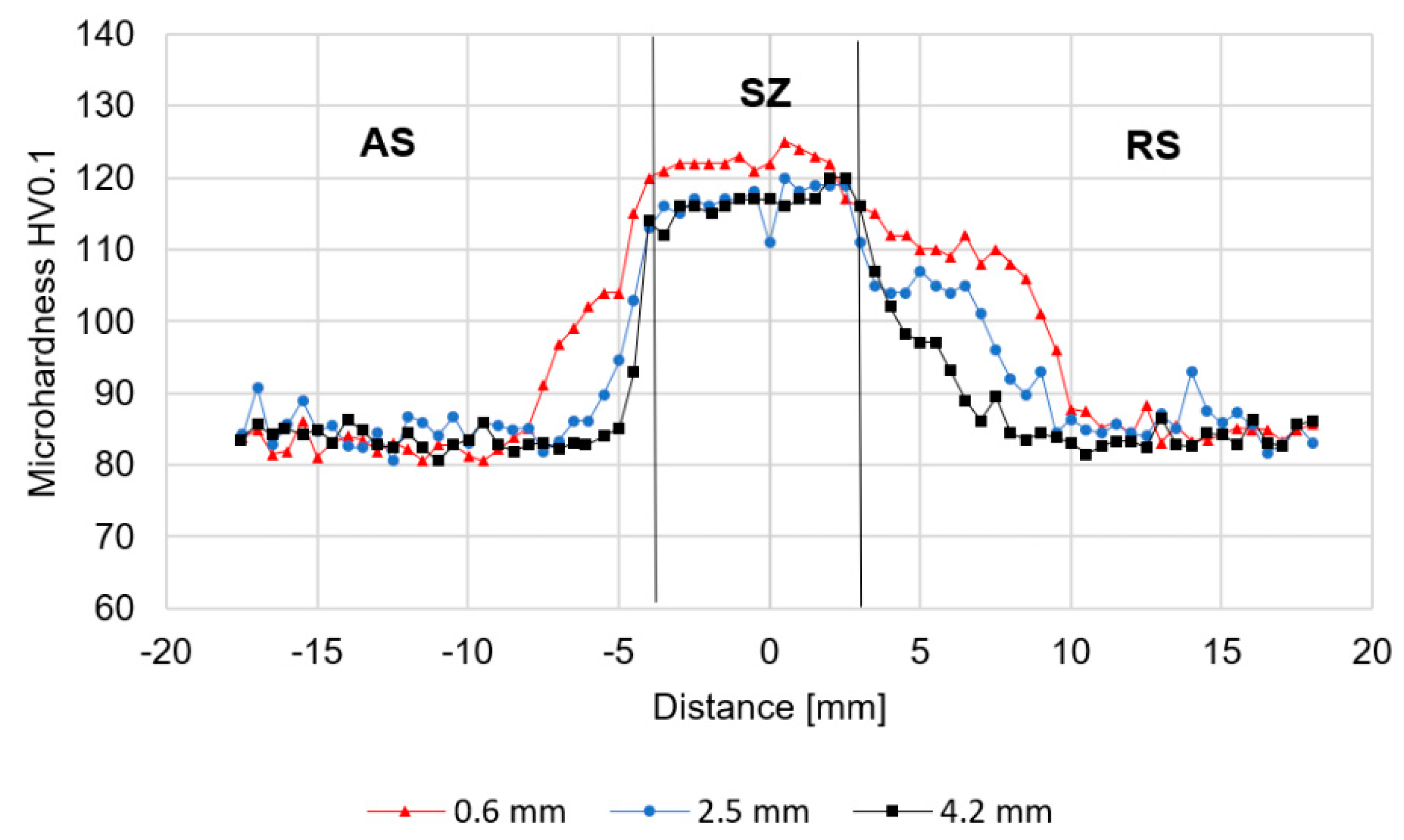
Despite the used welding parameters, the estimated joint efficiency contains within the range of 87–96% with the highest values of 94.3% and 95.4% reported in the samples A88 and A82 respectively. The lowest values of joint efficiency correspond to the samples A81 (87.5%) and A41 (88.9%). Although, in the same samples fracture location occurs far from the stir zone, the heat of the process affects the workpiece the most due to the low value of the tool traverse speed (100 mm/min). The initial increase of the welding speed also results in increasing joint efficiency, especially in the samples obtained with 800 rpm tool rotation speed. Samples A42, A44, A84, and A88 do not show such differences in their joint efficiency considering the scatter of tensile strength results. At the same time, the established elongation of the investigated joints has a lower fluctuation of values and is contained within the range of 6–10% with the highest differences occurring between the samples A81 (6.6%) and A82 (9.3%). The presence of the imperfections in the joints of samples A44 and A88 does not cause the failure in the stir zone during the tensile test (Figure 3a,c and Table 5). For microhardness analysis and fracture surface observations the following samples were chosen: A42 (the highest value of joint efficiency from 400 rpm series), A81, and A82 (the highest differences in joint efficiency). The microhardness distributions of the selected samples with indicated advancing sides (AS), retreating sides (RS), and stir zones (SZ) are presented in Figure 10, Figure 11 and Figure 12.
In all analyzed samples the affecting of the tool resulted in increasing of the microhardness from circa 86 HV0.1 (base material) to 110–125 HV0.1 in the stir zone. This increase depends on performed welding parameters and in the case of the A42 sample, the value of the stir zone microhardness is mainly 110 HV0.1, while for A81 it is around 115 HV0.1. At the same time, in the sample A82 in the upper part of the joint, the value of 125 HV0.1 was reported and 117 HV0.1 for lower parts of the analyzed cross-section. By comparing the distribution of microhardness for A81 and A82 samples, it can be observed that increasing the tool traverse speed results in narrowing of the stir zone from 8.5 to 7 mm, maintaining the characteristic distribution for the thermo-mechanically affected zone for both the advancing and the retreating side. This phenomenon can be explained by shorter time of acting of the tool on the workpiece in the sample with higher value of the tool traverse speed. Although, sample A42 is characterized by the most significant fluctuations in the microhardness distribution from all three samples subjected to the microhardness analysis, the obtained results are mostly compatible with the macrostructure observations (Figure 2b). The shape of the stir zone is more oblique than in case of A81 and A82 samples. The fluctuations in the microhardness within the stir zone are the result of the low heat input since the forming of the joint involves many heat-activated phenomena including grain recovery and recrystallization when the plastic deformation is not supported by the sufficient amount of heat, and the mentioned processes cannot be completed [51,52]. The high values of the microhardness (126 HV0.1) exceeding the measurements in the stir zone (110 HV0.1) are the result of hard Al2Cu precipitate’s presence in the non-heat-treated alloy. This differences in the distribution of hard precipitates between the stir zone and base material are possible to observe by scanning electron microscopy (Figure 13a,b).
In all analyzed samples the heat-affected zone (which can be identified by the lower value of the microhardness comparing to the base material) is difficult to distinguish. During the welding process, the heat-affected zone is an area in which undesirable heat-activated process took places including grain growth, overaging of strengthening phase (in case of precipitated hardened aluminum alloys), and as an additional factor, this zone has the highest value of residual stress [3,20,53]. The overaging of θ΄ phase is the main reason for the softening of the heat-treated AA2519 in the heat-affected zone [20,54]. The alloy used in this investigation was in the non-heat-treated condition and for this reason, there is no θ΄ phase to overage. Furthermore, the used extrusion has a very low value of microhardness (86 HV0.1) compared to the same material after the rolling process (circa 105 HV0.1) [10], what suggests a significantly lower level of the strain hardening of the extruded AA2519. For all the above reasons, it is difficult to unequivocally identify the heat-affected zone in the investigated joints. A lack of the significant softening of the joined material finds its reflection in the fracture location of the samples subjected to the tensile testing, as well as in the results of fracture surfaces analysis (Table 5, Figure 14).
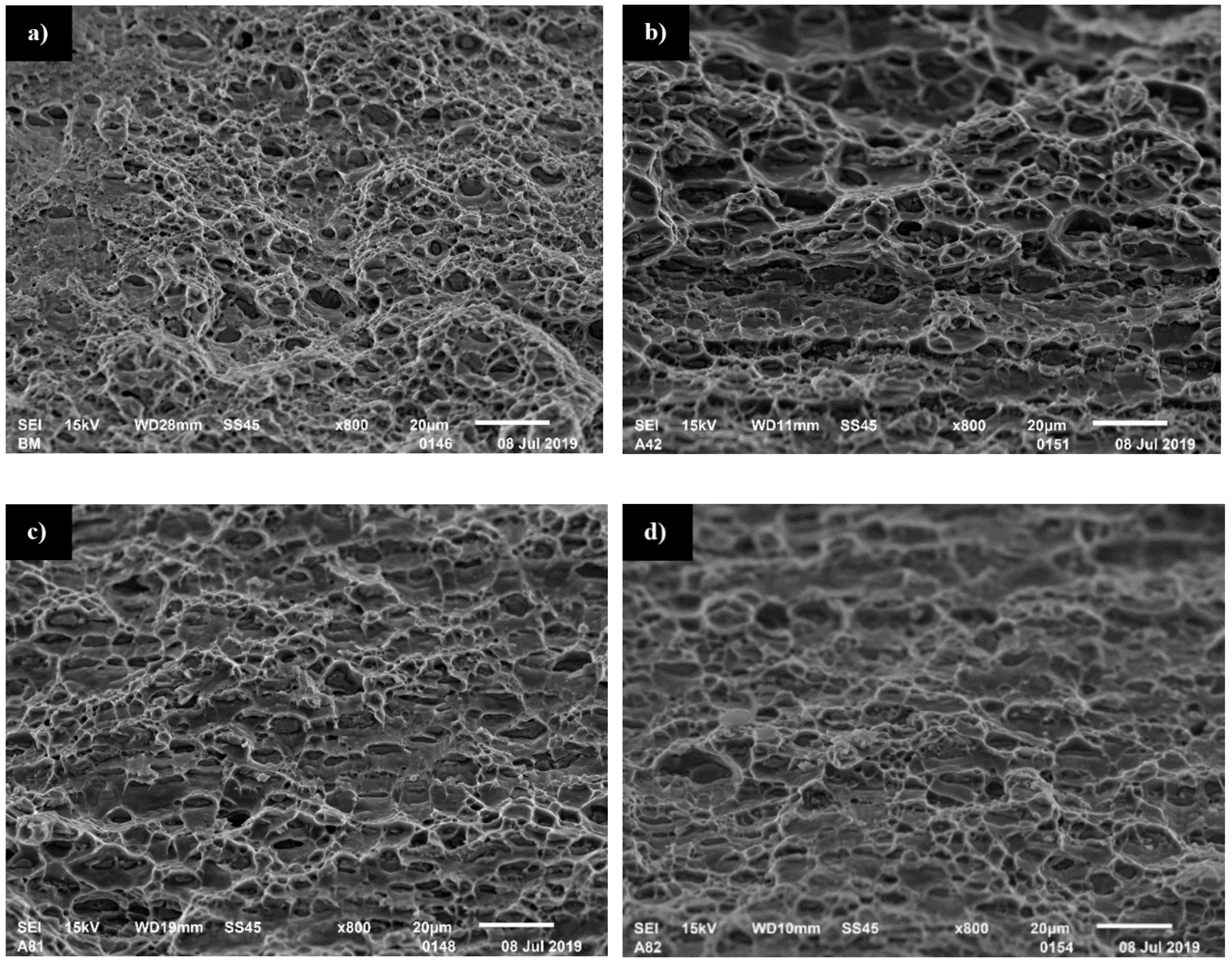
The analysis of the fracture location shows that failure occurs at a 45° angle corresponding to the maximum shear plane. The fracture surface of base material exhibits mixed ductile and brittle mode with the predominance of ductile fracture (Figure 14a). The characteristic dimple structure is the result of the presence of hard Al2Cu precipitates in the alloy microstructure. Although fracture surfaces of A81 and A82 samples seem to be more similar to each other in terms of dimple structure, the structure itself is only determined by the size of precipitates, which causes the larger size of dimples in the A42 sample (Figure 14b–d). Despite these differences, the character of fracture remains the same for all analyzed samples and base material, confirming the results of microhardness analysis.
4. Conclusions
The performed research on friction stir welding of Sc-modified AA2519 extrusion allowed the following conclusions to be drawn:
- Friction stir welding allows to obtain a high-quality joint of non-heat-treated Sc-modified AA2519 with the joint efficiency reaching 87–95%.
- The microstructure of the stir zone performed with the low ratio of the tool rotation speed to the tool traverse speed is characterized by the presence of defects (voids) and areas of deformed non-recrystallized grains.
- As the result of dynamic recrystallization, the microhardness of the joined material value of 86 HV0.1 increased to about 110–125 HV0.1 in the stir zone depending on the used welding parameters.
- Due to lack of the strengthening phase and low strain hardening of used alloy, the heat-affected zone is difficult to identify. The investigation of the fractured samples confirmed no presence of a significantly softened zone.
In this investigation, the highest joint efficiency of 95% was achieved for joints obtained using the tool rotation speed of 800 rpm, the tool traverse speed of 200 mm/min, the axial force of 17 kN, and the MX Triflute tool. This joint is also characterized by the highest elongation (9%) and has a defect-free microstructure, confirming high suitability of the mentioned parameters in terms of joining Sc-modified AA2519 extrusion in non-heat-treated conditions.
Author Contributions
Conceptualization, R.K. and L.Ś.; methodology, R.K. and M.W.; validation, R.K., L.Ś.; formal analysis, M.W., R.K and J.T.; investigation, M.W, R.K. and J.T.; resources, R.K.; data curation, M.W. and R.K.; writing—original draft preparation, R.K. and M.W.; writing—review and editing, R.K. and M.W.; visualization, R.K. and M.W.; supervision, L.Ś.; project administration, L.Ś.; funding acquisition, L.Ś.
Funding
This research was funded by Polish Ministry of National Defence, grant number: PBG/13-998.
Conflicts of Interest
The authors declare no conflict of interest.
References
- Mishra, R.S.; Mahoney, M.W. Friction Stir Welding and Processing; ASM International: Materials Park, OH, USA, 2007; ISBN 978-0-87170-840-3. [Google Scholar]
- Radisavljevic, I.; Zikovic, A.; Radovic, N.; Grabulov, V. Influence of FSW parameters on formation quality and mechanical properties of Al 2042–T351 butt welded joints. Trans. Nonferrous Met. Soc. China 2013, 23, 3525–3539. [Google Scholar] [CrossRef]
- Çam, G.; Mistikoglu, S. Recent Developments in Friction Stir Welding of Al-alloys. J. Mater. Eng. Perform. 2014, 23, 1936–1953. [Google Scholar] [CrossRef]
- Cabibbo, M.; Paoletti, C.; Ghat, M.; Archimede, F.; Simoncini, M. Post-FSW Cold-Rolling Simulation of ECAP Shear Deformation and Its Microstructure Role Combined to Annealing in a FSWed AA5754 Plate Joint. Materials 2019, 12, 1536. [Google Scholar] [CrossRef] [PubMed]
- Zhang, C.; Wang, W.; Jin, X.; Rong, C.; Qin, Z. A Study on Microstructure and Mechanical Properties of Micro Friction Stir Welded Ultra-Thin Al-1060 Sheets by the Shoulderless Tool. Metals 2019, 9, 507. [Google Scholar] [CrossRef]
- Vijayakumar, S.; Balaji, J.; Ramesh, S.; Prince, L. Assessment of Microstructure and Mechanical Properties of Stir Zone Seam of Friction Stir Welded Magnesium AZ31B through Nano-SiC. Materials 2019, 12, 1044. [Google Scholar] [CrossRef]
- Ren, D.; Zeng, F.; Liu, Y.; Liu, L.; He, Z. Friction Stir Welding of 5754 Aluminum Alloy with Cover Sheet. Materials 2019, 12, 1765. [Google Scholar] [CrossRef] [PubMed]
- Barabi, A.; Zarei Hanzaki, A.; Abedi, Hamid, R.; Anoushe, A.; Cho, J. The Correlation of Macrostructure, Microstructure, and Texture with Room Temperature Mechanical Properties of a Twinning-Induced Plasticity Automotive Steel after Friction Stir Spot Welding/Processing. Steel Res. Int. 2018, 89, 1800245. [Google Scholar] [CrossRef]
- Dialami, N.; Cervera, M.; Chiumenti, M. Effect of the Tool Tilt Angle on the Heat Generation and the Material Flow in Friction Stir Welding. Metals 2019, 9, 28. [Google Scholar] [CrossRef]
- Kosturek, R.; Śnieżek, L.; Wachowski, M.; Torzewski, J. The Influence of Post-Weld Heat Treatment on the Microstructure and Fatigue Properties of Sc-Modified AA2519 Friction Stir-Welded Joint. Materials 2019, 12, 583. [Google Scholar] [CrossRef]
- Kosturek, R.; Wachowski, M.; Ślęzak, T.; Śnieżek, L.; Mierzyński, J.; Sobczak, U. Research on the friction stir welding of Titanium Grade 1. In Proceedings of the International Conference on Advanced Functional Materials and Composites (ICAFMC2018), MATEC Web of Conferences 242, Barcelona, Spain, 5–6 September 2018. [Google Scholar]
- Schaffer, G.B.; Sercombe, T.B.; Lumley, R.N. Liquid phase sintering of aluminium alloys. Mater. Chem. Phys. 2001, 67, 85–91. [Google Scholar] [CrossRef]
- Gödecke, T.; Sommer, F. Solidification behavior of the Al2Cu phase. Zeitschrift für Metallkunde 1996, 87, 581–586. [Google Scholar]
- Häusler, I.; Schwarze, C.; Bilal, M.; Ramirez, D.; Hetaba, W.; Kamachali, R.; Skrotzki, B. Precipitation of T1 and θ′ Phase in Al-4Cu-1Li-0.25Mn During Age Hardening: Microstructural Investigation and Phase-Field Simulation. Materials 2017, 10, 117. [Google Scholar] [CrossRef] [PubMed]
- Gündüz, M.; Çadırlı, E. Directional solidification of aluminium–copper alloys. Mater. Sci. Eng. A Struct. 2002, 327, 167–185. [Google Scholar] [CrossRef]
- Stoichev, N.V.; Yaneva, S.B.; Regel, L.L.; Videnskiy, I.V. Eutectic solidification of Al–Cu alloys influenced by convection. Adv. Space Res. 1998, 8, 171–174. [Google Scholar] [CrossRef]
- Sinha, V.C.; Kundu, S.; Chatterjee, S. Microstructure and mechanical properties of similar and dissimilar joints of aluminium alloy and pure copper by friction stir welding. Perspect. Sci. 2016, 8, 543–546. [Google Scholar] [CrossRef] [Green Version]
- Cao, G.; Kou, S. Friction Stir Welding of 2219 Aluminum: Behavior of (Al2Cu) particles. Weld. J. 2005, 84, 1–7. [Google Scholar]
- Hsu, C.J.; Kao, P.W.; Ho, N.J. Ultrafine-grained Al–Al2Cu composite produced in situ by friction stir processing. Scr. Mater. 2005, 53, 341–345. [Google Scholar] [CrossRef]
- Liang, X.; Li, H.; Li, Z.; Hong, T.; Ma, B.; Liu, S.; Liu, Y. Study on the microstructure in a friction stir welded 2519-T87 Al alloy. Mater. Des. 2012, 35, 603–608. [Google Scholar] [CrossRef]
- Rao, C.V.; Reddy, G.M.; Rao, K.S. Microstructure and pitting corrosion resistance of AA2219 Al–Cu alloy friction stir welds—Effect of tool profile. Def. Technol. 2015, 11, 123–131. [Google Scholar] [CrossRef]
- Babu, S.; Elangovan, K.; Balasubramanian, V. Optimizing friction stir welding parameters to maximize tensile strength of AA2219 aluminum alloy joints. Met. Mater. Int. 2009, 15, 321–330. [Google Scholar] [CrossRef]
- Starke, E.A., Jr.; Staley, J.T. Application of modern aluminum alloys to aircraft. Prog. Aerosp. Sci. 1996, 32, 131–172. [Google Scholar] [CrossRef]
- Fisher, J.; James, J. Aluminum alloy 2519 in military vehicles. Mater. Sci. Forum 2002, 160, 43–46. [Google Scholar]
- Wachowski, M.; Kosturek, R.; Śnieżek, L.; Mróz, S.; Gloc, M.; Krawczyńska, A.; Malek, M. Analysis of the microstructure of an AZ31/AA1050/AA2519 laminate produced using the explosive-welding method. Mater. Tehnol. 2019, 53, 239–243. [Google Scholar] [CrossRef]
- Wachowski, M.; Fras, T.; Kosturek, R.; Śnieżek, L.; Szachogluchowicz, I.; Grzelak, K. The Effect of Hypervelocity Impact Loading on Explosively Welded Ti/Al/Al Plate. In Proceedings of the 2018 International Conference on Materials Science and Manufacturing Engineering (MSME 2018), Paris, France, 8–10 November 2018; Volume 253. [Google Scholar]
- Zakharov, V.V. Combined alloying of aluminium alloys with scandium and zirconium. Met. Sci. Heat Treat. 2014, 56, 281–286. [Google Scholar] [CrossRef]
- Davydov, V.G.; Elagin, V.I.; Zakharov, V.V.; Rostova, T.D. Alloying aluminium alloys with scandium and zirconium additives. Met. Sci. Heat Treat. 1996, 38, 347–352. [Google Scholar] [CrossRef]
- Zakharov, V.V. Effect of Scandium on the structure and properties of aluminium alloys. Met. Sci. Heat Treat. 2003, 45, 246. [Google Scholar] [CrossRef]
- Jia, Z.H.; Røyset, J.; Solberg, J.K.; Liu, Q. Formation of precipitates and recrystallization resistance in Al–Sc–Zr alloys. Trans. Nonferrous Met. Soc. China 2012, 22, 1866–1871. [Google Scholar] [CrossRef]
- Feng, J.C.; Chen, Y.; Liu, H. Effects of post-weld heat treatment on microstructure and mechanical properties of friction stir welded joints of 2219-O aluminium alloy. Mater. Sci. Eng. A Struct. 2006, 22, 86–90. [Google Scholar] [CrossRef]
- Suenger, S.; Kreissle, M.; Kahnert, M.; Zaeh, M.F. Influence of Process Temperature on Hardness of Friction Stir Welded High Strength Aluminum Alloys for Aerospace Applications. Procedia CIRP 2014, 24, 120–124. [Google Scholar] [CrossRef] [Green Version]
- Khan, N.Z.; Bajaj, D.; Siddiquee, A.N.; Khan, Z.A.; Abidi, M.H.; Umer, U.; Alkhalefah, H. Investigation on Effect of Strain Rate and Heat Generation on Traverse Force in FSW of Dissimilar Aerospace Grade Aluminium Alloys. Materials 2019, 12, 1641. [Google Scholar] [CrossRef]
- Sajuri, Z.; Selamat, N.M.; Baghdadi, A.H.; Kokabi, A.H.; Junaidi, S. Effect of Rolling on Strength of Friction Stir Welded Joint of Aluminium Alloys. Jurnal Kejuruteraan SI 2018, 1, 9–15. [Google Scholar] [CrossRef]
- Mehtedi, M.E.; Archimede, F.; Panaccio, L.; Simoncini, M. Design of Stamping Processes of Pinless FSWed Thin Sheets in AA1050 Alloy for Motomotive Applications Using FEM. Procedia Eng. 2017, 183, 213–218. [Google Scholar] [CrossRef]
- Simoncini, M.; Archimede, F.; Panaccio, L. Bending and Stamping Processes of FSWed Thin Sheets in AA1050 Alloy. Key Eng. Mater. 2014, 622–623, 459–466. [Google Scholar] [CrossRef]
- Haghshenas, M.; Gerlich, A.P. Joining of automotive sheet materials by friction-based welding methods: A review. Eng. Sci. Technol. Int. J. 2018, 21, 130–148. [Google Scholar] [CrossRef]
- De Filippis, L.; Serio, L.; Palumbo, D.; De Finis, R.; Galietti, U. Optimization and characterization of the Friction Stir Welded Sheets of AA 5754-H111: Monitoring of the quality of joints with thermographic techniques. Materials 2017, 9, 122. [Google Scholar] [CrossRef] [PubMed]
- De Filippis, L.A.C.; Serio, L.M.; Facchini, F.; Mummolo, G.; Ludovico, A.D. Prediction of the Vickers Microhardness and Ultimate Tensile Strength of AA5754 H111 Friction Stir Welding Butt Joints Using Artificial Neural Network. Materials 2016, 9, 915. [Google Scholar] [CrossRef] [PubMed]
- Tamjidy, M.; Hang Tuah Baharudin, B.T.; Paslar, S.; Matori, K.A.; Sulaiman, S.; Fadaeifard, F. Multi-Objective Optimization of Friction Stir Welding Process Parameters of AA6061-T6 and AA7075-T6 Using a Biogeography Based Optimization Algorithm. Materials 2017, 10, 533. [Google Scholar] [CrossRef]
- Padhy, G.; Wu, C.S.; Gao, S. Friction stir based welding and processing technologies—Processes, parameters, microstructures and applications: A review. J. Mater. Sci. Technol. 2018, 34, 1–38. [Google Scholar] [CrossRef]
- Seung-Ju, S.; Jungseok, K.; Woo, L.; Jae Yong, L.; Yohan, G.; Young, K. Influence of Friction Stir Welding on Mechanical Properties of Butt Joints of AZ61 Magnesium Alloy. Adv. Mater. Sci. Eng. 2017, 2017, 7381403. [Google Scholar] [CrossRef]
- Sabari, S.S.; Malarvizhi, V.; Balasubramanian, V. Influences of tool traverse speed on tensile properties of air cooled and water cooled friction stir welded AA2519-T87 aluminium alloy joints. J. Mater. Process. Technol. 2016, 237, 286–300. [Google Scholar] [CrossRef]
- ASTM. ASTM Standard E8/E8M—13a: Standard Test. Methods for Tension Testing of Metallic Materials; ASTM: West Conshoboken, PA, USA, 2013. [Google Scholar]
- Ravi Raja, A.; Yusufzai, M.Z.; Vashista, M. Characterization of advancing and retreating weld of friction stir welding of aluminium. In Proceedings of the ICAMM 2016, Bangkok, Thailand, 29–30 October 2016; pp. 3–8. [Google Scholar]
- Tufaro, L.; Manzoni, I.; Svoboda, H. Effect of Heat Input on AA5052 Friction Stir Welds Characteristics. Proc. Mater. Sci. 2015, 8, 914–923. [Google Scholar] [CrossRef] [Green Version]
- Prangnell, P.; Heason, C. Grain structure formation during friction stir welding observed by the ‘stop action technique’. Acta Mater. 2005, 53, 3179–3192. [Google Scholar] [CrossRef]
- De Meer, S.; Drury, M.R.; Bresser, J.H.P.; Pennock, G.M. Current issues and new developments in deformation mechanisms, rheology and tectonics. Geol. Soc. Lond. Spec. Publ. 2002, 200, 1–27. [Google Scholar] [CrossRef]
- Fan, X.; Li, M.; Li, D.; Shao, Y.; Zhang, S.; Peng, Y. Dynamic recrystallisation and dynamic precipitation in AA6061 aluminium alloy during hot deformation. Mater. Sci. Technol. 2014, 30, 1263–1272. [Google Scholar] [CrossRef]
- Jones, J.M.; Humphreys, J.F. Interaction of recrystallization and precipitation: The effect of Al3Sc on the recrystallization behaviour of deformed aluminium. Acta Mater. 2003, 51, 2149–2159. [Google Scholar] [CrossRef]
- Salih, O.S.; Neate, N.; Ou, H.; Sun, W. Influence of process parameters on the microstructural evolution and mechanical characterisations of friction stir welded Al–Mg–Si alloy. J. Mater. Process. Technol. 2019, 275, 116366. [Google Scholar] [CrossRef]
- Su, J.Q.; Nelson, T.; Sterling, J.C. Microstructure evolution during FSW/FSP of high strength aluminum alloys. Mat. Sci. Eng. A Struct. 2005, 405, 277–286. [Google Scholar] [CrossRef]
- Staron, P.; Koçak, M.; Williams, S. Residual stresses in friction stir welded Al sheets. Appl. Phys. A 2002, 74, 1161. [Google Scholar] [CrossRef]
- Sabari, S.; Malarvizhi, S.; Balasubramanian, V. Characteristics of FSW and UWFSW joints of AA2519-T87 aluminium alloy: Effect of tool rotation speed. J. Manuf. Process. 2016, 22, 278–289. [Google Scholar] [CrossRef]
Figure 1.
Scheme of sample for tensile testing. All dimensions are in mm.

Figure 2.
Light microscopy images of the 2519 friction stir welding (FSW) joint: (a) A41, (b) A42, (c) A44, (d) A81, (e) A82, (f) A84, (g) A88. AS—advancing side, RS—retreating side.
Figure 2.
Light microscopy images of the 2519 friction stir welding (FSW) joint: (a) A41, (b) A42, (c) A44, (d) A81, (e) A82, (f) A84, (g) A88. AS—advancing side, RS—retreating side.


Figure 3.
Light microscopy image of (a) voids in the A88 sample, (b) bands in the A88 sample, (c) bands in the A44 sample, and (d) stir zone of the A44 sample. Voids are indicated by yellow arrows.
Figure 3.
Light microscopy image of (a) voids in the A88 sample, (b) bands in the A88 sample, (c) bands in the A44 sample, and (d) stir zone of the A44 sample. Voids are indicated by yellow arrows.

Figure 4.
Light microscopy image of the stir zone in the (a) A42 sample and (b) A81 sample.

Figure 5.
Light microscopy image of the stir zone with the distinctive areas in the (a) A41 sample and (b) A81 sample.
Figure 5.
Light microscopy image of the stir zone with the distinctive areas in the (a) A41 sample and (b) A81 sample.

Figure 6.
Tensile curves for joints obtained with the tool rotation speed of 400 rpm.

Figure 7.
Tensile curves for joints obtained with the tool rotation speed of 800 rpm.

Figure 8.
Established mechanical properties for joints obtained with the tool rotation speed of 400 rpm.
Figure 8.
Established mechanical properties for joints obtained with the tool rotation speed of 400 rpm.
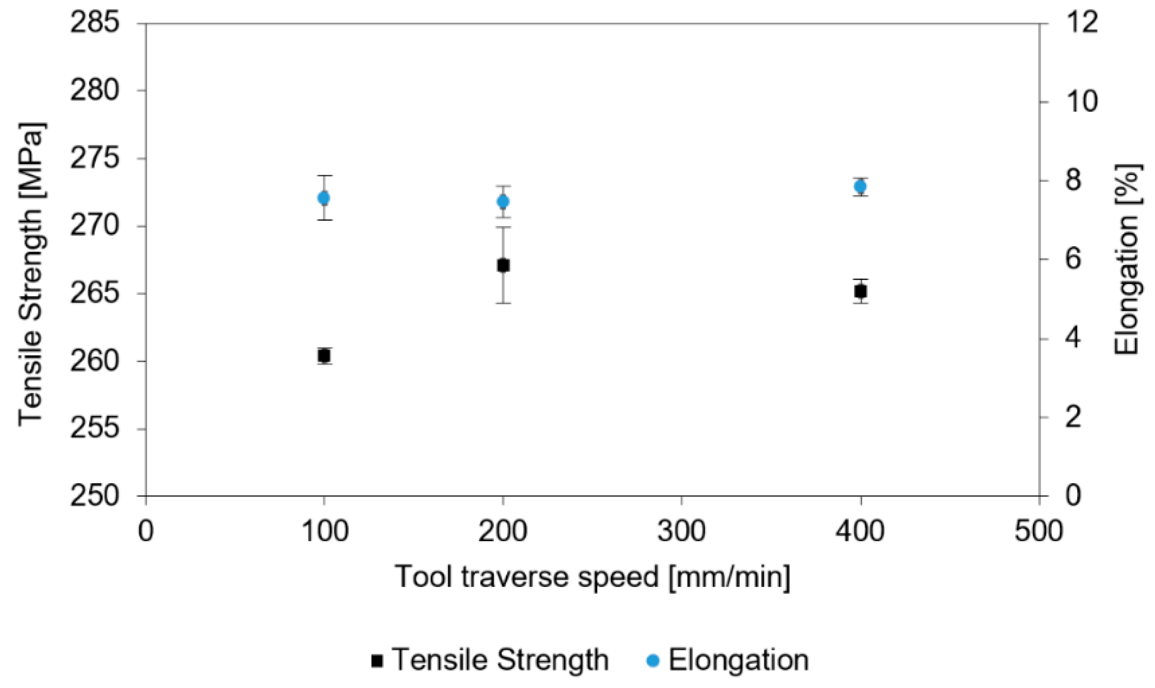
Figure 9.
Established mechanical properties for joints obtained with the tool rotation speed of 800 rpm.
Figure 9.
Established mechanical properties for joints obtained with the tool rotation speed of 800 rpm.
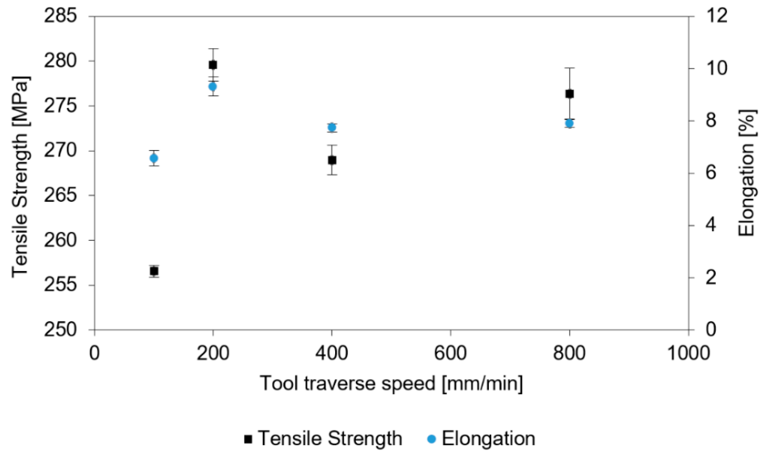
Figure 10.
Distribution of microhardness in the A42 sample with respect to the distance from the top of the joint.
Figure 10.
Distribution of microhardness in the A42 sample with respect to the distance from the top of the joint.
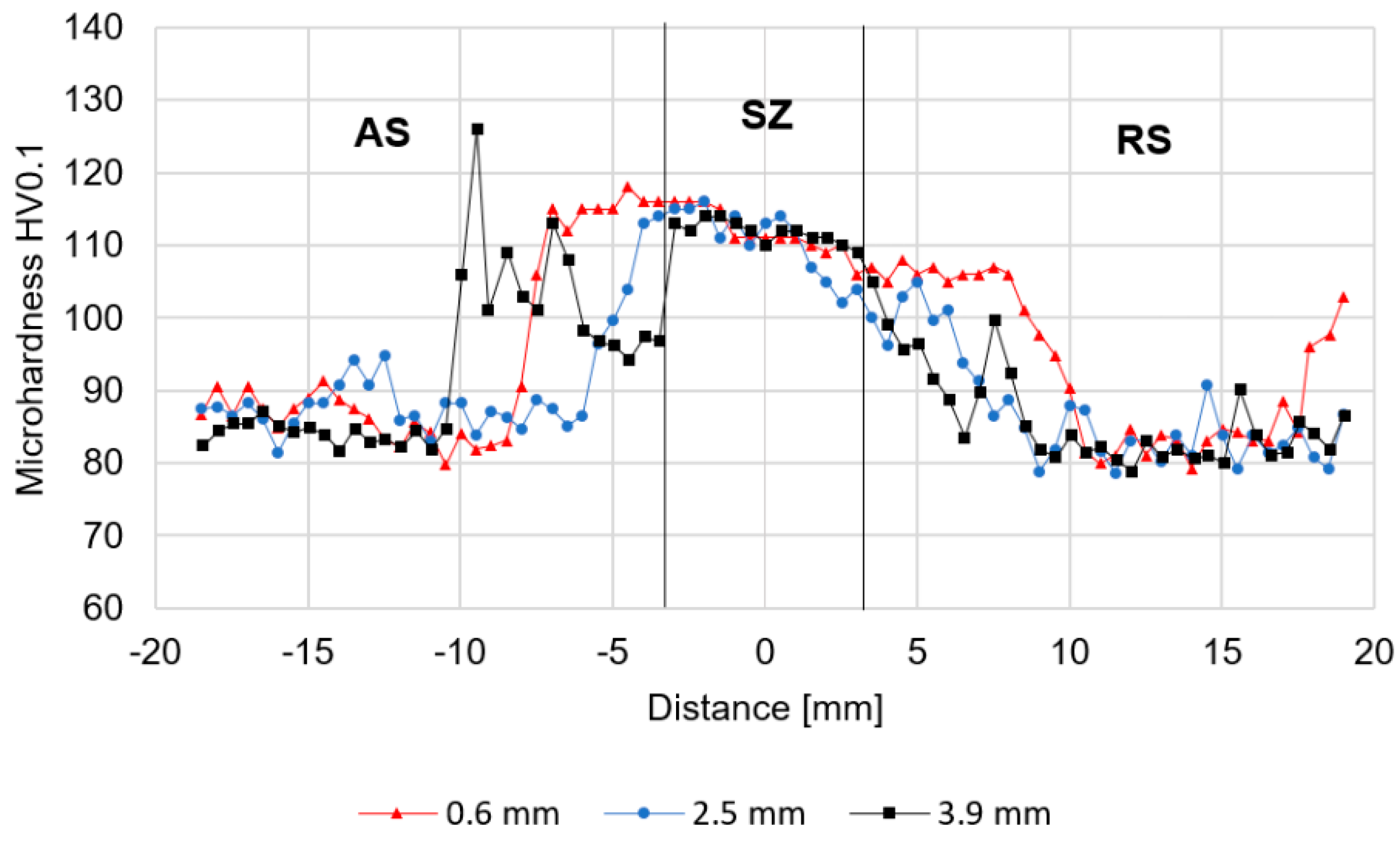
Figure 11.
Distribution of microhardness in the A81 sample with respect to the distance from the top of the joint.
Figure 11.
Distribution of microhardness in the A81 sample with respect to the distance from the top of the joint.

Figure 12.
Distribution of microhardness in the A82 sample with respect to the distance from the top of the joint.
Figure 12.
Distribution of microhardness in the A82 sample with respect to the distance from the top of the joint.

Figure 13.
Scanning electron microscopy images of the (a) stir zone and (b) base material.

Figure 14.
Scanning electron microscopy images of fracture surface of the (a) base material, (b) A42 sample, (c) A81 sample, and (d) A82 sample.
Figure 14.
Scanning electron microscopy images of fracture surface of the (a) base material, (b) A42 sample, (c) A81 sample, and (d) A82 sample.

Table 1.
Chemical composition of AA2519 extrusion to be welded.
| Fe | Si | Cu | Zn | Ti | Mn | Mg | Ni | Zr | Sc | V | Al |
|---|---|---|---|---|---|---|---|---|---|---|---|
| 0.11 | 0.08 | 6.32 | 0.05 | 0.08 | 0.17 | 0.33 | 0.02 | 0.19 | 0.16 | 0.10 | Base |
Table 2.
Mechanical properties of AA2519 extrusion to be welded.
| Yield Strength | Tensile Strength | Elongation |
|---|---|---|
| 207 MPa | 293 MPa | 16.1% |
Table 3.
The dimensions of the MX Triflute tool used.
| Shoulder Profile | Spiral |
|---|---|
| Shoulder diameter | 19 mm |
| Pin profile | Threaded and tapered with three spiral flutes |
| Pin length | 4.8 mm |
| Pin diameter | 6.5–8.7 mm |
Table 4.
Welding parameters for each sample with designation.
| Sample Designation | Tool Rotation Speed (ω) (rpm) | Tool Traverse Speed (v) (mm/min) | Heat Input (Q) Ratio ω/v |
|---|---|---|---|
| A41 | 400 | 100 | 4 |
| A42 | 400 | 200 | 2 |
| A44 | 400 | 400 | 1 |
| A81 | 800 | 100 | 8 |
| A82 | 800 | 200 | 4 |
| A84 | 800 | 400 | 2 |
| A88 | 800 | 800 | 1 |
Table 5.
Established joint efficiency and fracture location of examined samples.
© 2019 by the authors. Licensee MDPI, Basel, Switzerland. This article is an open access article distributed under the terms and conditions of the Creative Commons Attribution (CC BY) license (http://creativecommons.org/licenses/by/4.0/).
Share and Cite
MDPI and ACS Style
Kosturek, R.; Śnieżek, L.; Torzewski, J.; Wachowski, M. Research on the Friction Stir Welding of Sc-Modified AA2519 Extrusion. Metals 2019, 9, 1024. https://doi.org/10.3390/met9101024
AMA Style
Kosturek R, Śnieżek L, Torzewski J, Wachowski M. Research on the Friction Stir Welding of Sc-Modified AA2519 Extrusion. Metals. 2019; 9(10):1024. https://doi.org/10.3390/met9101024
Chicago/Turabian StyleKosturek, Robert, Lucjan Śnieżek, Janusz Torzewski, and Marcin Wachowski. 2019. "Research on the Friction Stir Welding of Sc-Modified AA2519 Extrusion" Metals 9, no. 10: 1024. https://doi.org/10.3390/met9101024
Note that from the first issue of 2016, this journal uses article numbers instead of page numbers. See further details here.